


SSC-E413P
4-112-197-01 (1)
Color Video Camera
彩色摄像机
Operating Instructions
Before operating the unit, please read this manual thoroughly and
retain it for future reference.
使用手册
使用本机器前,请仔细阅读本实用手册并妥善保存以备日后参考。
WARNING
To reduce a risk of fire or electric shock, do not
expose this product to rain or moisture.
To avoid electrical shock, do not open the cabi-
net. Refer servicing to qualified personnel only.
The apparatus shall not be exposed to dripping or splashing and no
objects filled with liquid, such as vases, shall be placed on the appara-
tus.
WARNING (SSC-E418P only)
The mains plug must be used to disconnect mains power. Please
ensure that the socket outlet is installed near the equipment and shall
be easily accessible.
For the customers in Europe
The manufacturer of this product is Sony Corporation, 1-7-1 Konan,
Minatoku, Tokyo, Japan.
The Authorized Representative for EMC and product safety is Sony
Deutschland GmbH, Hedelfinger Strasse 61, 70327 Stuttgart, Germany.
For any service or guarantee matters please refer to the addresses
given in separate service or guarantee documents.
For the customers in Europe, Australia and New Zealand
WARNING
This is a Class A product. In a domestic environment, this product may
cause radio interference in which case the user may be required to take
adequate measures.
In the case that interference should occur, consult your nearest
authorized Sony service facility.
This apparatus shall not be used in the residential area.
ATTENTION
The electromagnetic fields at specific frequencies may influence the
picture of this unit.
Caution
This installation should be made by a qualified service person and
should conform to all local codes.
CAUTION
The rating label is located on the top.
English
This manual applies to the SSC-E413P and SSC-E418P. The operating
instructions apply to these cameras, but their signal systems and power
requirements are different.
Signal system Power requirements
SSC-E413P PAL color system DC 12 V ± 10 % or
AC 24 V ± 10 %, 50 Hz
SSC-E418P PAL color system AC 220-240 V ± 10 %, 50 Hz
Features
The color video camera is designed for use in a monitoring system.
• High resolution and high sensitivity with a 1/3 type Super HAD CCD II
as the imaging device
• CCD-IRIS function
• Automatic white balance tracking and adjustment (ATW)
• DC controlled auto iris lenses
• BLC (Backlight Compensation) through the center measurement
• LEVEL adjustment for various lighting conditions
• Power supply: Automatically switched between DC 12 V and AC 24 V
(SSC-E413P)
• AC line lock and INT
• The built-in tripod screws are located on both the top and bottom of
the camera.
* Super HAD CCD II is a trademark of Sony Corporation.
Notes on Use
Power supply
• The SSC-E413P operates on either DC 12 V or AC 24 V (50 Hz)
power. The SSC-E413P automatically detects the power.
– When connecting the transformer, be sure to connect each lead to
the appropriate terminal. Wrong connection may cause malfunction
and/or damage to the video camera.
– Ground the unit or an irregular voltage may be generated in the AC
power cord and may cause malfunction and/or damage to the video
camera.
• The SSC-E418P must always be operated with an AC 220 - 240 V
(50 Hz) power supply.
Handling of the unit
Be careful not to spill water or other liquids on the unit, or to get
combustible or metallic material inside the body. If used with foreign
matter inside, the camera is liable to fail, or to cause fire or electric
shock.
Operating and storage locations
Avoid aiming the camera at very bright objects such as the sun or
electric lights for an expanded period. Avoid operating or storing the unit
in the following locations.
• Extremely hot or cold places (operating temperature –10°C to +50°C;
14°F to 122°F, however, we recommend that the unit be used within a
temperature range of 0°C to +35°C; 32°F to 95°F.)
• Damp or dusty places
• Where it is exposed to rain
• Where it is subject to strong vibration and shock
• Close to generators of powerful electromagnetic radiation such as
radio or TV transmitters
• Where it is subject to fluorescent light reflections
• Where it is subject to unstable (flickering, etc.) lighting conditions
Care of the unit
• Remove dust or dirt from the surface of the lens or CCD with a blower.
• Use a dry soft cloth to clean the body. If it is very dirty, use a cloth
dampened with a small quantity of neutral detergent, then wipe dry.
• Avoid the use of volatile solvents such as thinners, alcohol, benzene,
and insecticides. They may damage the surface finish and/or impair
the operation of the camera.
Other
• When BLC is in the “ON” position, “hunting” may occur, that is, the
image may get darker and lighter as the camera “hunts” for the best
exposure level. If hunting occurs, set the BLC switch to “OFF.”
• If you use the CCD-IRIS function in locations where the camera is
exposed to fluorescent light, a slow color change may occur.
In the event of any problems with the operation of the camera, contact
your Sony service representative.
Note on laser beams
Laser beams may damage the CCDs. If you shoot a scene that
includes a laser beam, be careful not to let a laser beam become
directed into the lens of the camera.
Installation
WARNING
• If you attach the camera in the height such as the wall or the ceiling,
etc., entrust the installation to an experienced contractor or installer.
• If you install the camera on the ceiling, ensure that the ceiling is strong
enough to withstand the weight (20 Kg) of the camera plus the bracket
and then install the camera securely. If the ceiling is not strong
enough, the camera may fall and cause serious injury.
• To prevent the camera from falling, make sure to attach the supplied
wire rope.
• If you attach the camera to the ceiling, check periodically, at least once
a year, to ensure that the connection has not loosened. If conditions
warrant, make this periodic check more frequently.
Suitable lenses
The lens must be a CS-mount type lens weighing less than 1 kg. The
protrusion behind the mounting surface must be 4 mm or less.
Installation of an Auto Iris Lens Connector
D
Install the lens connector (not supplied) when using an Auto Iris Lens.
This installation should be done only by qualified service personnel or
system installers. A lens connector is not included with this camera package.
1 Cut the iris control cable at the edge of the lens connector to remove
the existing lens connector and then remove the outer cable cover
as shown in the diagram on the left.
2 Solder the lens cable to the pins of the lens connector.
Fitting the lens
E
1 Unscrew the lens mount cap.
2 Screw in the lens, and turn it until it is secured.
3 Insert the lens plug in the LENS connector.
When fitting a manual-iris lens, omit step 3.
4 According to the type of lens, adjust the focal length by turning the
focal length adjustment screw.
Caution
• Keep the lens mount cap on the camera when it is not attached to the
lens.
• Check the lens mount
Check the lens mount at least once a year to ensure it has not become
loose. If conditions warrant, make this periodic check more frequently.
Installing the camera
ATTENTION
If installing the camera on the ceiling, be sure it is secure. If not
securely installed, the camera may fall and injury may occur.
If the camera is installed on the ceiling using equipment such as a
bracket, housing and motored swivel base (pan/tilt), do the following:
• Use tripod screws and securely tighten them with a driver. Order the
tripod screws (Sony Part No. 3-174-693-02) from your nearest Sony
dealer.
• Install the tripod screw on a flat surface.
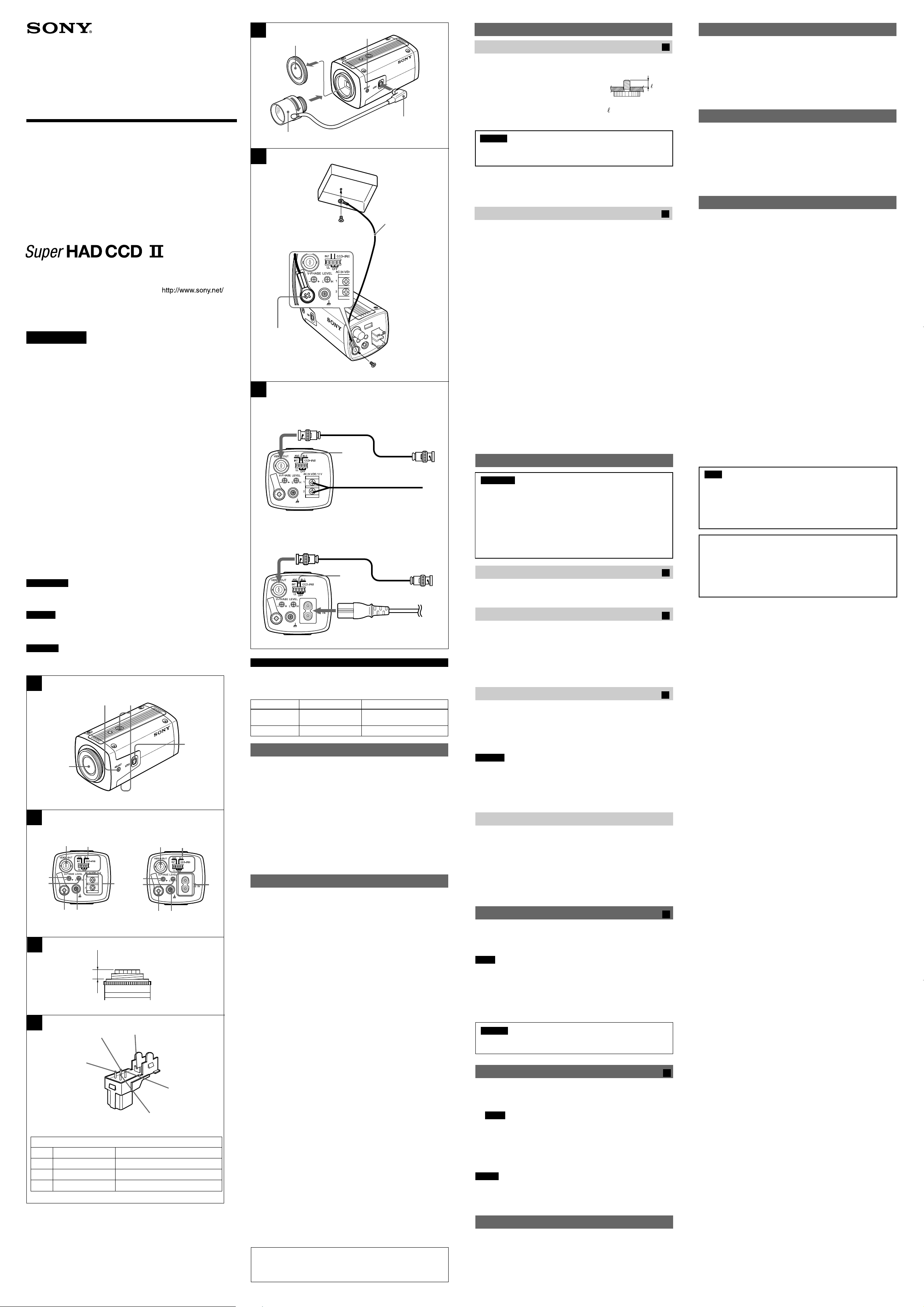
Attaching the fall-prevention wire rope
F
When you install the camera on a ceiling or a high position, be sure to attach
the supplied fall-prevention wire rope to prevent the camera from falling.
Attach the fall-prevention wire rope to the screw hole on the rear of the
camera, as in the illustration.
Note
Take care not to short-circuit the power terminal or the cable with the
wire rope when you attach it.
1 Secure the wire rope to the junction box on the ceiling.
Use a screw to match the screw hole of your junction box (not supplied).
2 Secure the wire rope to the wire rope mounting screw hole on the
rear of the camera using the supplied screw.
Caution
Use the supplied screws for installation. If not, the wire rope may not
function properly.
Connecting the Camera
G
1 Connect the video cable to the VIDEO OUT connector.
2 Connect the video cable to the VIDEO IN connector of a video
monitor, etc.
3 Select the synchronization system using the sync (INT/LL) switch.
Note
Use this switch to set the camera synchronization mode to internal
or line lock. The line lock is available only for AC 24 V. When the
camera power is DC 12 V, be sure to select the internal mode.
4 Connect the power source using the power cable.
SSC-E413P: to a DC 12 V or an AC 24 V power source
SSC-E418P: to an AC 220 - 240 V power source
Notes
• Be sure to input only the proper voltage to the power terminal of the
camera.
• Be sure to push the power cord all the way in.
Phase Adjustment
Vertical phase
The picture may roll vertically if the vertical phase is not set. Use the V
PHASE adjustment screw to adjust the vertical phase.
SSC-E413P/E418P
2008 Sony Corporation Printed in China
D
3
1
2
4
Rib
Lens Connector (not supplied)
C
Rib (If the cable is thick, cut this off.)
Pin 4 DC control Drive – (Ground)
Pin 2 DC control Control +
Pin 1 DC control Control –
Pin 3 DC control Drive +
4 mm or less
B
SSC-E413P SSC-E418P
6
7
+
–
5
q;
9
qs
qa
5
6
8
9
q;
qa
qs
A
12
4
3
E
SSC-E413P
F
+
–
4
2
1
3
1
4
2
3
75-ohm coaxial cable
Power cable
SSC-E418P
2
1
4
3
75-ohm coaxial cable
Power cable
G
Fall-prevention wire
rope (supplied)
screw (not supplied)
2
1
Location and Function of Parts
Top/Bottom/Front/Rear/Side
A
1 Focal length adjustment
Use this screw to adjust the focal length (the distance between the lens
mounting plane and the image plane).
2 Tripod screws
The screw holes for attaching the tripod are
located on both the top and bottom of the
camera. Use a 1/4" UNC-20 screw to attach a
tripod to the camera. The tripod must be set up
on a flat surface and tightened firmly by hand.
Caution
Use the mounting screw whose length is 4.5 mm – 7 mm only. Use of
other screws may cause improper mounting and damage parts inside
the camera.
3 LENS connector (4 pin socket)
Supplies power and control signals to an auto iris lens.
4 Lens mount
Use to mount an appropriate CS-mount lens.
Switch/Terminal area
5 VIDEO OUT connector (BNC-type)
6 Mode switches
Sync (INT/LL) switch
Use to select the synchronization system from INT (Internal) or LL
(Line Lock).
AGC switch
Use to increase the gain of the video amplifier when dark.
BLC switch
When set to “BLC”, adjusts exposure to compensate for situations
where the subject is lit from behind.
CCD-IRIS switch
When using a manual iris lens, set this to “CCD-IRIS” to automati-
cally adjust the sensitivity according to the incidental light conditions.
When using an auto iris lens, set this to “OFF.”
7 AC 24 V/DC 12 V screw terminals (SSC-E413P)
Connect to an external power supply of AC 24 V or DC 12 V.
8 AC IN (SSC-E418P)
Connect this to a 220 V to 240 V AC power supply.
9 Ground terminal (screw type)
Connect this terminal to the ground, when noise occurs.
q; Fall-prevention wire rope mounting screw hole
When installing the camera to a ceiling or wall, secure the supplied fall-
prevention wire rope to this hole using the supplied screw.
qa LEVEL adjustment screw
Use to adjust the iris level when you are using a DC controlled auto iris lens.
qs V PHASE adjustment screw
Use to adjust the vertical phase of cameras synchronized by Line lock.
U1/4”, 20 UNC
== 4.5 mm – 7 mm
(ISO standard) (with the
screws fastened)
Adjusting the Incident Light Level
Since the incidental light level has been preset at the factory, usually no
further adjustment is required. If the picture is too dark, however, or if
the picture’s highlights are extremely overexposed, adjust the LEVEL
adjustment screw with a screwdriver. This adjustment can only be used
for DC controlled auto iris lens.
1 Turn toward L (low) to make the picture darker.
2 Turn toward H (high) to make the picture brighter.
CCD Characteristics
The following conditions may be observed when using a CCD camera,
but are not due to any fault with the camera.
Vertical smear: This phenomenon occurs when viewing a very bright
object.
Patterned noise: This is a fixed pattern which may appear over the
entire monitor screen when the camera is operated at high temperature.
Jagged picture: When viewing stripes, straight lines, or similar
patterns, the image on the screen may appear jagged.
Specifications
Imaging device 1/3type interline transfer CCD
Picture elements 752 (horizontal) × 582 (vertical)
Lens mount CS-mount
Signal system PAL color system
Sync system Internal/AC line lock
Horizontal resolution 540 lines
Minimum illumination 0.3lx (F1.2, 50IRE, AGC ON)
S/N 50 dB (AGC OFF)
White Balance ATW
Video output 1 Vp-p, 75 ohm, negative sync
CCD iris 1/50 to 1/100,000 sec
Automatic Gain Control Switchable: ON (Turbo mode)/OFF
Power requirements SSC-E413P:
DC 12 V ±10%/AC 24 V ±10%, 50 Hz
SSC-E418P:
AC 220 - 240 V ±10%, 50 Hz
Power consumption 3.5 W
Operating temperature –10°C to +50°C (14°F to 122°F)
Operating humidity 20 to 80%
Storage temperature –40°C to +60°C (–40°F to +140°F)
Storage humidity 20 to 95%
Mass SSC-E413P:
Approx. 360 g (12.7 oz)
SSC-E418P:
Approx. 385 g (13.6 oz)
Dimensions (w/h/d) 60 × 54 × 120 mm (2
3
/
8
× 2
1
/
4
× 4
3
/
4
inches)
Supplied accessories Lens mount cap (1)
Operating Instructions (1)
Fall-prevention wire rope (1)
Screw 3 M4 × 8 (1)
Power cable (1) (SSC-E418P only)
Design and specifications are subject to change without notice.
Note
Always verify that the unit is operating properly before use. SONY WILL
NOT BE LIABLE FOR DAMAGES OF ANY KIND INCLUDING, BUT
NOT LIMITED TO, COMPENSATION OR REIMBURSEMENT ON
ACCOUNT OF THE LOSS OF PRESENT OR PROSPECTIVE
PROFITS DUE TO FAILURE OF THIS UNIT, EITHER DURING THE
WARRANTY PERIOD OR AFTER EXPIRATION OF THE WARRANTY,
OR FOR ANY OTHER REASON WHATSOEVER.
Regular parts replacement
Some of the parts that make up this product (electrolytic condenser,
for example) need replacing regularly depending on their life
expectancies. The lives of parts differ according to the environment
or condition in which this product is used and the length of time it is
used, so we recommend regular checks.
Consult the dealer from whom you bought it for details.
Screw (supplied)
B
C
 Loading...