


SS-CT100D/WGV100D/ZX80DP/ ZX100D/ZX100DP
SERVICE MANUAL
E Model
Ver. 1.0 2006.05
Photo: SS-CT100D |
Photo: SS-WGV100D |
Photo: SS-ZX100D |
•SS-CT100D is center speaker in FST-ZX80D/ZX100D/LBT-ZX80D/ZX100D.
•SS-WGV100D is subwoofer in FST-ZX100D/LBT-ZX100D.
•SS-ZX100D is front and surround speakers in FST-ZX80D/ZX100D/LBT-ZX80D/ZX100D.
•SS-ZX80DP is package speaker of front and surround speakers in FST-ZX80D/LBT-ZX80D.
•SS-ZX100DP is package speaker of front and surround speakers in FST-ZX100D/LBT-ZX100D.
|
SS-ZX80DP |
SS-ZX100DP |
|
|
|
Front Speaker |
SS-ZX100D |
|
|
|
|
Surround Speaker |
SS-ZX100D |
|
|
|
|
SPECIFICATIONS
Front/Surround speaker SS-ZX100D
Speaker system |
2-way, bass-reflex type, |
|
|
magnetically shielded |
|
Speaker units |
|
|
Woofer |
22 cm, cone type |
|
Tweeter |
5 cm, cone type × |
2 |
Nominal impedance |
6 ohms |
|
Dimensions (w/h/d) |
Approx. 308 × 365 × |
|
|
480 mm |
|
Mass |
Approx. 10.0 kg net per |
|
|
speaker |
|
Center Speaker SS-CT100D |
|
|
Speaker system |
Full range, 2-unit, |
|
|
bass-reflex type, |
|
|
magnetically shielded |
|
Speaker units |
8 cm, cone type × |
|
Full range |
2 |
|
Nominal Impedance |
16 ohms |
|
Dimensions (w/h/d) |
Approx. 268 × 107 × |
|
|
117 mm |
|
Mass |
Approx. 1.6 kg |
|
Subwoofer |
|
SS-WGV100D |
|
Subwoofer system |
1-way, 1-unit, |
|
bass-reflex type, |
|
magnetically shielded |
Speaker units |
|
Subwoofer: |
20 cm, cone type |
Nominal impedance |
8 ohms |
Dimensions (w/h/d) (Approx.) |
|
|
281 × 362 × 338.5 mm |
Mass |
(Approx.) 6.8 kg |
Design and specifications are subject to change without notice.
•JIG
When disassembling the set, use the following jig (for speaker removal).
Part No.: J-2501-238-A JIG FOR SPEAKER REMOVAL
SPEAKER SYSTEM
9-887-256-01 |
Sony Corporation |
|
2006E05-1 |
Home Audio Division |
© 2006.05 |
Published by Sony Techno Create Corporation |
SS-CT100D/WGV100D/ZX80DP/ZX100D/ZX100DP
Notes on chip component replacement
•Never reuse a disconnected chip component.
•Notice that the minus side of a tantalum capacitor may be damaged by heat.
SECTION 1
GENERAL
This section is extracted from instruction manual.
UNLEADED SOLDER
Boards requiring use of unleaded solder are printed with the leadfree mark (LF) indicating the solder contains no lead.
(Caution: Some printed circuit boards may not come printed with the lead free mark due to their particular size)
 : LEAD FREE MARK
Unleaded solder has the following characteristics.
•Unleaded solder melts at a temperature about 40 ˚C higher than ordinary solder.
Ordinary soldering irons can be used but the iron tip has to be applied to the solder joint for a slightly longer time. Soldering irons using a temperature regulator should be set to about 350 ˚C.
Caution: The printed pattern (copper foil) may peel away if the heated tip is applied for too long, so be careful!
•Strong viscosity
Unleaded solder is more viscou-s (sticky, less prone to flow) than ordinary solder so use caution not to let solder bridges occur such as on IC pins, etc.
•Usable with ordinary solder
It is best to use only unleaded solder but unleaded solder may also be added to ordinary solder.
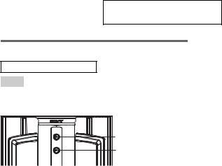
Subwoofer (SS-WGV100D)
ALPHABETICAL ORDER
A – Z
SUBWOOFER ON/OFF 1
SUBWOOFER LEVEL 2
1
2
2

SS-CT100D/WGV100D/ZX80DP/ZX100D/ZX100DP
SECTION 2
DISASSEMBLY
Note: Follow the disassembly procedure in the numerical order given.
2-1. FRONT PANEL BLOCK (SS-WGV100D)
3 Raise the front panel assy a little by little from bottom to top of the set.
1Insert a flat-tip screwdriver into a recess in the bottom of the set
to raise the front panel assy a little.
2 Insert the jig (J-2051-238-A) into a space made by inserting the screwdriver,
and raise the front panel assy gradually.
4 front panel block
3
 Loading...