


Sony SSCT-1000-D, SSCT-999-D, SSGN-1000-D, SSGN-1000-S, SSGN-999-D Service manual
...
SS-CT999D/CT1000D/GN999D/GN999S/GN1000D/ GN1000S/RSX999D/RSX1000D/WGV999D/WGV1000D
SERVICE MANUAL
E Model
Ver. 1.0 2006. 05
Photo : SS-RSX999D Photo : SS-GN999D Photo : SS-RSX1000D Photo : SS-WGV999D Photo : SS-WGV1000D
COMPONENT MODEL NAME
System name |
|
MHC-GN999D |
|
MHC-GN999DS |
|
|||
Destination |
|
E2, E51, MX |
|
EXCEPT E2, E51, MX |
|
|||
FRONT SPEAKERS |
|
SS-GN999D |
|
SS-GN999S |
|
|||
SURROUND SPEAKERS |
|
|
SS-RSX999D |
|
||||
CENTER SPEAKER |
|
|
SS-CT999D |
|
||||
SUB WOOFER |
|
|
SS-WGV999D |
|
||||
DVD PLAYER DECK RECEIVER |
|
|
HCD-GN999D |
|
||||
|
|
|
|
|
|
|
|
|
|
|
|
|
|
|
|
|
|
System name |
|
|
MHC-GN1000D |
|
||||
Destination |
|
E2 |
|
EXCEPT E2 |
|
|||
|
|
|
|
|
|
|
|
|
FRONT SPEAKERS |
|
SS-GN1000DP |
SS-GN1000D |
SS-GN1000SP |
SS-GN1000S |
|
||
SURROUND SPEAKERS |
|
|
SS-RSX1000D |
SS-RSX1000D |
|
|||
|
|
|
|
|
||||
CENTER SPEAKER |
|
|
|
SS-CT1000D |
|
|||
|
|
|
|
|
|
|
|
|
SUB WOOFER |
|
HCR-GN1000D |
|
SS-WGV1000D |
|
|||
|
|
|
|
|
|
|
|
|
DVD PLAYER DECK |
|
|
|
HCD-GN1000D |
|
|||
|
|
|
|
|||||
RECEIVER SYSTEM |
|
|
|
|
|
|||
|
|
|
|
|
|
|
||
• Abbreviation |
|
• JIG |
|
|
|
|
||
E2 : 120 V AC Area in E model |
When disassembling the set, use the following jig (for |
|||||||
E51 : Chilean and Peruvian model |
speaker removal). |
|||||||
MX : Mexican model |
Part No.: J-2501-238-A JIG FOR SPEAKER REMOVAL |
|||||||
CENTER SPEAKER/FRONT SPEAKERS/
SURROUND SPEAKERS/SUB WOOFER
9-887-255-01 |
Sony Corporation |
2006E02-1 |
Home Audio Division |
© 2006.05 |
Published by Sony Techno Create Corporation |
SS-CT999D/CT1000D/GN999D/GN999S/GN1000D/GN1000S/RSX999D/RSX1000D/WGV999D/WGV1000D
SPECIFICATIONS
For MHC-GN999D/MHC-GN999DS
• Front speaker (SS-GN999D/SS-GN999S)
Speaker system |
2-way, 2-unit, bass-reflex type, |
|
magnetically shielded |
Speaker units |
|
Woofer: |
20 cm, cone type |
Tweeter: |
2.5 cm, horn type |
Nominal impedance |
6 ohms |
Dimensions (w/h/d) |
Approx. 281 x 417 x 310.5 mm |
Mass |
Approx. 7.2 kg net per speaker |
• Surround speaker (SS-RSX999D) |
|
Speaker system |
Full range, 2-unit, bass-reflex |
|
type |
Speaker units |
|
Full range: |
8 cm, cone type x 2 |
Nominal impedance |
16 ohms |
Dimensions (w/h/d) |
Approx. 268 x 107 x 117 mm |
Mass |
Approx. 1.4 kg net per speaker |
• Center speaker (SS-CT999D) |
|
Speaker system |
Full range, 2-unit, bass-reflex |
|
type, magnetically shielded |
Speaker units |
|
Full range: |
8 cm, cone type x 2 |
Nominal impedance |
16 ohms |
Dimensions (w/h/d) |
Approx. 268 x 107 x 117 mm |
Mass |
Approx. 1.6 kg |
• Sub woofer (SS-WGV999D) |
|
Speaker system |
1-way, 1-unit, bass-reflex type, |
|
magnetically shielded |
Speaker units |
|
Woofer: |
20 cm, cone type |
Nominal Impedance |
6 ohms |
Dimensions (w/h/d) |
Approx. 262 x 327 x 370 mm |
Mass |
Approx. 6.6 kg |
For MHC-GN1000D
• Front speaker (SS-GN1000D (Latin American models only)/ SS-GN1000S (Other models))
Speaker system
Speaker units
Woofer:
Tweeter:
Nominal impedance
Dimensions (w/h/d)
Mass
•Surround speaker (SS-RSX1000D)
Speaker system Speaker units Woofer: Tweeter:
Nominal impedance Dimensions (w/h/d) Mass
•Center Speaker (SS-CT1000D)
Speaker system
Speaker units
Full range:
Nominal Impedance
Dimensions (w/h/d)
Mass
• Subwoofer (SS-WGV1000D)
Subwoofer system
Speaker units
Subwoofer:
Nominal impedance
Dimensions (w/h/d)
Mass
2-way, 2-unit, bass-reflex type, magnetically shielded
20 cm, cone type
2.5 cm, horn type
6 ohms
Approx. 281 x 417 x 310.5 mm Approx. 7.2 kg net per speaker
2-way, 2-units, bass-reflex type
10 cm, cone type
5 cm, horn type
6 ohms
Approx. 176 x 362 x 215 mm Approx. 2.9 kg net per speaker
Full range, 2-unit, bass-reflex type, magnetically shielded
8 cm, cone type x 2
6 ohms
Approx. 268 x 107 x 117 mm Approx. 1.6 kg
1-way, 1-unit, bass-reflex type, magnetically shielded
20 cm, cone type
8 ohms
Approx. 281 × 362 × 338.5 mm Approx. 6.8 kg
Design and specifications are subject to change without notice.
2
SS-CT999D/CT1000D/GN999D/GN999S/GN1000D/GN1000S/RSX999D/RSX1000D/WGV999D/WGV1000D
SECTION 1
DIAGRAMS
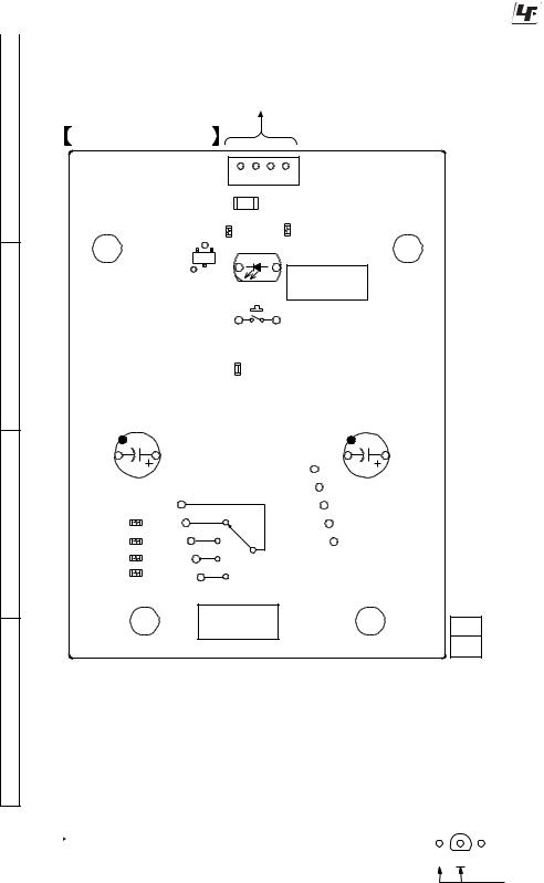
1-1. PRINTED WIRING BOARD (SS-WGV1000D) |
: Uses unleaded solder. |
||
|
|
|
|
1 |
2 |
3 |
|
|
HCD-GN1000D |
|
|
A |
SWPANEL BOARD |
|
CN1400 |
1 |
|
|
|
|
JR1400 |
|
|
E |
R1406 |
D1400 |
|
||
|
|
|
Q1400
S1400
4 R1405
SUBWOOFER
ON/OFF
B
C
D
C1401 |
JR1402 |
C1400 |
|
R1401
R1402
R1403
R1404
SW1400
SUBWOOFER
LEVEL 11 1-868-600- (11)
Unleaded solder
Boards requiring use of unleaded solder are printed with the lead free mark (LF) indicating the solder contains no lead.
(Caution: Some printed circuit boards may not come printed with the lead free mark due to their particular size.)
 : LEAD FREE MARK
Unleaded solder has the following characteristics.
•Unleaded solder melts at a temperature about 40°C higher than ordinary solder.
Ordinary soldering irons can be used but the iron tip has to be applied to the solder joint for a slightly longer time.
Soldering irons using a temperature regulator should be set to about 350°C.
Caution: The printed pattern (copper foil) may peel away if the heated tip is applied for too long, so be careful!
•Strong viscosity
Unleaded solder is more viscous (sticky, less prone to flow) than ordinary solder so use caution not to let solder bridges occur such as on IC pins, etc.
•Usable with ordinary solder
It is best to use only unleaded solder but unleaded solder may also be added to ordinary solder.
Note on Printed Wiring Boards:
•X : parts extracted from the component side.
• : Pattern from the side which enables seeing. (The other layers' patterns are not indicated.)
•Indication of transistor.
Q
B C E
These are omitted.
3
SS-CT999D/CT1000D/GN999D/GN999S/GN1000D/GN1000S/RSX999D/RSX1000D/WGV999D/WGV1000D
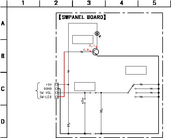
1-2. SCHEMATIC DIAGRAM (SS-WGV1000D)
|
D1400 |
|
|
|
|
SELU5420E |
|
|
|
|
GREEN |
|
|
|
|
SUBWOOFER |
|
|
|
|
ON/OFF |
|
Q1400 |
|
|
|
|
|
|
|
|
|
2SC2712 |
|
|
|
|
LED DRIVE |
|
|
R1406 |
|
|
|
|
1k |
|
|
|
|
|
|
SW1400 |
|
|
R1405 |
|
SUBWOOFER |
|
|
1k |
|
LEVEL |
|
CN1400 |
|
|
|
|
|
|
R1401 |
R1402 |
|
4P |
S1400 |
|
||
|
|
2.2k |
6.8k |
|
|
SUBWOOFER |
|||
|
|
|
||
HCD-GN1000D |
ON/OFF |
|
|
|
|
|
|
|
|
|
|
JR1402 |
|
|
|
|
0 |
R1404 |
R1403 |
|
|
|
||
|
|
|
68k |
22k |
|
|
|
C1401 |
|
|
|
|
1 |
|
|
|
|
50V |
|
|
C1400 |
|
|
|
|
10 |
JR1400 |
|
|
|
50V |
|
|
|
|
0 |
|
|
|
|
|
|
|
|
Note on Schematic Diagram:
• All capacitors are in µF unless otherwise noted. (p: pF) 50 WV or less are not indicated except for electrolytics and tantalums.
• All resistors are in Ω and 1/4 W or less unless otherwise specified.
• C : panel designation.
•A : B+ Line.
•Voltages are dc with respect to ground in service mode. no mark : POWER ON
•Voltages are taken with a VOM (Input impedance 10 MΩ ).
Voltage variations may be noted due to normal production tolerances.
4
 Loading...