

Sony MHC-V77DW Service Manual
MHC-V77DW
SERVICE MANUAL
Ver. 1.0 2016.08
Note:
Be sure to keep your PC used for service and
checking of this unit always updated with the
latest version of your anti-virus software.
In case a virus affected unit was found during
service, contact your Service Headquarters.
Model Name Using Similar Mechanism SA-WGT4D
DVD
Section
DVD Mechanism Type CDM90-DVBU204//M
Optical Pick-up Name CMS-S76RFS7G1 OR CMS-S76RFS7GP
AEP Model
UK Model
E Model
Australian Model
Speaker section
Speaker system:
Tweeter + Midrange speaker + Woofer
Speaker unit:
Tweeter L/R: 40 mm, cone type
Midrange L/R: 120 mm, cone type
Woofer: 250 mm, cone type
Rated impedance:
Tweeter L/R: 4 ohms
Midrange L/R: 4 ohms
Woofer: 8 ohms
Inputs
AUDIO/PARTY CHAIN IN (TV) L/R:
Voltage 2 V, impedance
47 kilohms
TV (ARC):
Supported audio signal:
2-channel Linear PCM
MIC1, MIC2:
Sensitivity 1 mV, impedance
10 kilohms
Outputs
AUDIO/PARTY CHAIN OUT L/R:
Voltage 2 V, impedance 1 kilohm
VIDEO OUT:
Max. output level 1 Vp-p,
unbalanced, Sync. negative load
impedance 75 ohms
HDMI OUT (TV):
Supported audio signal:
2-channel Linear PCM (up to
48 kHz), Dolby Digital
HDMI section
Connector:
Type A (19 pin)
Disc player section
System:
Compact disc and digital audio and
video system
SPECIFICATIONS
Laser Diode Properties
Emission Duration: Continuous
Laser Output*: Less than 44.6 μW
* This output is the value measurement
at a distance of 200 mm from the
objective lens surface on the Optical
Pick-up Block with 7 mm aperture.
Frequency response:
20 Hz – 20 kHz
Video color system format:
Latin American model:
NTSC
Other models:
NTSC and PAL
USB section
Supported USB device:
Mass Storage Class
Maximum current:
1 A
(USB) port:
Type A
FM tuner section
FM stereo, FM superheterodyne tuner
Antenna:
FM lead antenna
Tuning range:
87.5 MHz – 108.0 MHz (50 kHz step)
BLUETOOTH section
Communication system:
BLUETOOTH Standard version 4.2
Output:
BLUETOOTH Standard Power Class 1
Maximum communication range:
Line of sight approx. 30 m
Frequency band:
2.4 GHz band (2.4000 GHz –
2.4835 GHz)
Modulation method:
FHSS (Freq Hopping Spread Spectrum)
*1
Compatible BLUETOOTH profiles
A2DP (Advanced Audio Distribution
Profile)
AVRCP (Audio Video Remote
Control Profile)
SPP (Serial Port Profile)
Supported codecs:
SBC (Subband Codec)
AAC (Advanced Audio Coding)
LDAC
*1
The actual range will vary depending on
factors such as obstacles between devices,
magnetic fields around a microwave oven,
static electricity, reception sensitivity,
antenna’s performance, operating system,
software application, etc.
*2
BLUETOOTH standard profiles
indicate the purpose of BLUETOOTH
communication between devices.
Network section
Ethernet LAN
100BASE-TX
Wireless LAN
Compatible standards:
IEEE 802.11 a/b/g/n
Security:
WPA/WPA2-PSK, WEP
Radio frequency:
2.4 GHz, 5 GHz
Supported audio formats
Supported bit rate and sampling frequencies:
MP3:
16/22.05/24/32/44.1/48 kHz,
16 kbps – 320 kbps (CBR/VBR)
AAC:
16/22.05/24/32/44.1/48/88.2/96 kHz,
16 kbps – 320 kbps (CBR/VBR)
WMA:
32/44.1/48 kHz, 16 kbps – 320 kbps
(CBR/VBR)
*2
:
WAV:
16/22.05/24/32/44.1/48/88.2/96/
176.4/192 kHz (16/24 bit)
AIFF:
32/44.1/48/88.2/96/176.4/192 kHz
(16/24 bit)
FLAC:
16/22.05/24/32/44.1/48/88.2/96/
176.4/192 kHz (16/24 bit)
ALAC:
16/22.05/24/32/44.1/48/88.2/96/
176.4/192 kHz (16/24 bit)
DSD (DSF/DSDIFF):
2.8 MHz (1 bit)
Supported video formats
Xvid:
Video codec: Xvid video
Bit rate: 4.854 Mbps (MAX)
Resolution/Frame rate:
720 × 480, 30 fps
720 × 576, 25 fps (except for Latin
American model)
Audio codec: MP3
MPEG4:
File format: MP4 File Format
Video codec: MPEG4 Simple
Profile (AVC is not compatible.)
Bit rate: 4 Mbps
Resolution/Frame rate:
720 × 480, 30 fps
720 × 576, 25 fps (except for Latin
American model)
Audio codec: AAC-LC (HE-AAC is
not compatible.)
DRM: Not compatible
– Continued on next page –
9-890-683-01
2016H80-1
2016.08
©
HOME AUDIO SYSTEM
Sony Corporation
Published by Sony EMCS (Malaysia) PG Tec
MHC-V77DW
General
Power requirements:
AC 120 V – 240 V, 50/60 Hz
Power consumption:
220 W
Power consumption (at the Power Saving mode):
0.5 W (When “NW STBY” is set to “OFF” and
[CONTROL FOR HDMI] is set to [OFF].)
3 W* (When “NW STBY” is set to “ON” and
[CONTROL FOR HDMI] is set to [ON].)
Dimensions (W/H/D) (Approx.):
340 mm × 924 mm × 378 mm
Mass (Approx.):
22 kg
* The power consumption of the system will be less than 0.5 W
when there is no HDMI connection and “NW STBY” is set to
“OFF”.
Design and specifications are subject to change without notice.
License and Trademark Notice
is a trademark of DVD Format/Logo Licensing Corporation.
•
•
“DVD+RW”, “DVD-RW”, “DVD+R”, “DVD-R”,
the “CD” logos are trademarks.
• WALKMAN® and WALKMAN® logo are registered trademarks
of Sony Corporation.
• MPEG Layer-3 audio coding technology and patents licensed from
Fraunhofer IIS and Thomson.
• Windows Media is either a registered trademark or trademark of
Microsoft Corporation in the United States and/or other countries.
• This product is protected by certain intellectual property rights of
Microsoft Corporation. Use or distribution of such technology outside
of this product is prohibited without a license from Microsoft or an
authorized Microsoft subsidiary.
• This system incorporates Dolby* Digital.
* Manufactured under license from Dolby Laboratories. Dolby,
Dolby Audio, and the double-D symbol are trademarks of Dolby
Laboratories.
• This system incorporates High-Definition Multimedia Interface
(HDMI™) technology. The terms HDMI and HDMI HighDefinition Multimedia Interface, and the HDMI Logo are
trademarks or registered trademarks of HDMI Licensing LLC in
the United States and other countries.
• “BRAVIA” is a trademark of Sony Corporation.
• LDAC™ and LDAC logo are trademarks of Sony Corporation.
• The BLUETOOTH
trademarks owned by Bluetooth SIG, Inc. and any use of such
marks by Sony Corporation is under license. Other trademarks
and trade names are those of their respective owners.
• The N-Mark is a trademark or registered trademark of NFC Forum,
Inc. in the United States and in other countries.
• Android™ is a trademark of Google Inc.
• Google Play™ is a trademark of Google Inc.
• Google Cast™ is a trademark of Google Inc.
• Apple, the Apple logo, iPhone, and iPod touch are trademarks of
Apple Inc., registered in the U.S. and other countries. App Store
is a service mark of Apple Inc.
• “Made for iPod,” and “Made for iPhone” mean that an electronic
accessory has been designed to connect specifically to iPod or
iPhone, respectively, and has been certified by the developer to
meet Apple performance standards. Apple is not responsible for
the operation of this device or its compliance with safety and
regulatory standards. Please note that the use of this accessory
with iPod or iPhone may affect wireless performance.
®
, Wi-Fi Protected Access® and Wi-Fi Alliance® are
• Wi-Fi
registered trademarks of Wi-Fi Alliance
• Wi-Fi CERTIFIED™, WPA™, WPA2™ and Wi-Fi Protected
Setup™ are trademarks of Wi-Fi Alliance
• DLNA™, the DLNA Logo and DLNA CERTIFIED™ are
trademarks, service marks, or certification marks of the Digital
Living Network Alliance.
• AOSS is a trademark of BUFFALO INC.
• This product incorporates Spotify software which is subject to
3rd party licenses found here:
https://developer.spotify.com/
esdk-third-party-licenses/
• Spotify and Spotify logos are trademarks of the Spotify Group.
• ClearAudio+ and
Corporation.
• “Xperia” and “Xperia Tablet” are trademarks of Sony Mobile
Communications AB.
• THIS PRODUCT IS LICENSED UNDER THE MPEG-4 VISUAL
PATENT PORTFOLIO LICENSE FOR THE PERSONAL AND
NON-COMMERCIAL USE OF A CONSUMER FOR
(i) ENCODING VIDEO IN COMPLIANCE WITH THE MPEG-4
VISUAL STANDARD (“MPEG-4 VIDEO”)
AND/OR
(ii) DECODING MPEG-4 VIDEO THAT WAS ENCODED BY
A CONSUMER ENGAGED IN A PERSONAL AND NONCOMMERCIAL ACTIVITY AND/OR WAS OBTAINED FROM
A VIDEO PROVIDER LICENSED TO PROVIDE MPEG-4
VIDEO.
®
word mark and logos are registered
are trademarks of Sony
“DVD VIDEO”, and
®
.
®
.
NO LICENSE IS GRANTED OR SHALL BE IMPLIED FOR ANY
OTHER USE. ADDITIONAL INFORMATION INCLUDING THAT
RELATING TO PROMOTIONAL, INTERNAL AND COMMERCIAL USES AND LICENSING MAY BE OBTAINED FROM MPEG
LA, L.L.C.
HTTP://WWW.MPEGLA.COM
• All other trademarks are trademarks of their respective owners.
• In this manual, ™ and
Abbreviation
•
®
marks are not specified.
AUS : Australian model
E4 : African model
EA : Saudi Arabia model
LA9 : Latin-American model
MY : Malaysia model
RU : Russian model
TH : Thai model
SAFETY CHECK-OUT
After correcting the original service problem, perform the following
safety check before releasing the set to the customer:
Check the antenna terminals, metal trim, “metallized” knobs,
screws, and all other exposed metal parts for AC leakage. Check
leakage as described below.
LEAKAGE TEST
The AC leakage from any exposed metal part to earth ground and
from all exposed metal parts to any exposed metal part having a
return to chassis, must not exceed 0.5 mA (500 microamperes).
Leakage current can be measured by any one of three methods.
1. A commercial leakage tester, such as the Simpson 229 or RCA
WT-540A. Follow the manufacturers’ instructions to use these
instruments.
2. A battery-operated AC milliammeter. The Data Precision 245
digital multimeter is suitable for this job.
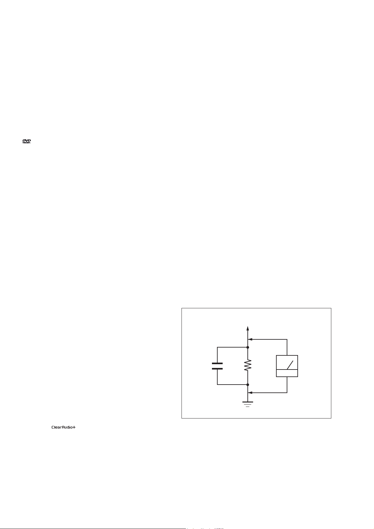
3. Measuring the voltage drop across a resistor by means of a
VOM or battery-operated AC voltmeter. The “limit” indication
is 0.75 V, so analog meters must have an accurate low-voltage
scale. The Simpson 250 and Sanwa SH-63Trd are examples
of a passive VOM that is suitable. Nearly all battery operated
digital multimeters that have a 2V AC range are suitable. (See
Fig. A)
To Exposed Metal
Parts on Set
AC
1.5 kΩ0.15 μF
voltmeter
(0.75 V)
Earth Ground
Fig. A. Using an AC voltmeter to check AC leakage.
SAFETY-RELATED COMPONENT WARNING!
COMPONENTS IDENTIFIED BY MARK 0 OR DOTTED LINE
WITH MARK 0 ON THE SCHEMATIC DIAGRAMS AND IN
THE PARTS LIST ARE CRITICAL TO SAFE OPERATION.
REPLACE THESE COMPONENTS WITH SONY PARTS
WHOSE PART NUMBERS APPEAR AS SHOWN IN THIS
MANUAL OR IN SUPPLEMENTS PUBLISHED BY SONY.
2

TABLE OF CONTENTS
MHC-V77DW
1. SERVICING NOTES ............................................. 4
2. DISASSEMBLY
2-1. Disassembly Flow ........................................................... 10
2-2. Rear Cover Assy ............................................................. 11
2-3. Side-L Panel .................................................................... 11
2-4. Panel Loading Section .................................................... 12
2-5. Top Panel Section ........................................................... 13
2-6. Side-R Panel ................................................................... 14
2-7. CDM Section .................................................................. 15
2-8. CDM90-DVBU204//M ................................................... 15
2-9. Service, Optical Device (7G), Flexible Flat Cable ......... 16
2-10. Back Panel Section ......................................................... 17
2-11. 2CH DAMP Board .......................................................... 18
2-12. BENTEN-MOTHERBOARD Board, 89G Board .......... 19
2-13. REGULATOR, SWITCHING (SSN-161AD) ................ 20
2-14. Front Panel Section ......................................................... 21
2-15. Loudspeaker (260mm)-180-11 (Woofer) (SP5) .............. 22
2-16. Loudspeaker (120mm)-181-11 (Mid: L-CH) (SP1),
Loudspeaker (120mm)-181-11 (Mid: R-CH) (SP3) ....... 22
3. TEST MODE ............................................................ 23
4. ELECTRICAL CHECK ......................................... 25
5. TROUBLESHOOTING .......................................... 27
6. DIAGRAMS
6-1. Block Diagram - RS SERVO, USB Section - ................. 31
6-2. Block Diagram - MEMORY Section - ............................ 32
6-3. Block Diagram - MAIN Section - ................................... 33
6-4. Block Diagram - AMP Section - ..................................... 34
6-5. Block Diagram
- PANEL, POWER SUPPLY Section - ........................... 35
6-6. Printed Wiring Board - BENTEN-MOTHERBOARD
Board (Component Side) - .............................................. 37
6-7. Printed Wiring Board - BENTEN-MOTHERBOARD
Board (Conductor Side) - ................................................ 38
6-8. Schematic Diagram
- BENTEN-MOTHERBOARD Board (1/11) - .............. 39
6-9. Schematic Diagram
- BENTEN-MOTHERBOARD Board (2/11) - .............. 40
6-10. Schematic Diagram
- BENTEN-MOTHERBOARD Board (3/11) - .............. 41
6-11. Schematic Diagram
- BENTEN-MOTHERBOARD Board (4/11) - .............. 42
6-12. Schematic Diagram
- BENTEN-MOTHERBOARD Board (5/11) - .............. 43
6-13. Schematic Diagram
- BENTEN-MOTHERBOARD Board (6/11) - .............. 44
6-14. Schematic Diagram
- BENTEN-MOTHERBOARD Board (7/11) - .............. 45
6-15. Schematic Diagram
- BENTEN-MOTHERBOARD Board (8/11) - .............. 46
6-16. Schematic Diagram
- BENTEN-MOTHERBOARD Board (9/11) - .............. 47
6-17. Schematic Diagram
- BENTEN-MOTHERBOARD Board (10/11) - ............ 48
6-18. Schematic Diagram
- BENTEN-MOTHERBOARD Board (11/11) - ............. 49
6-19. Printed Wiring Board
- SENSOR Board (Component Side) - ........................... 50
6-20. Printed Wiring Board
- SENSOR Board (Conductor Side) - ............................. 51
6-21. Schematic Diagram - SENSOR Board (1/3) - ................ 52
6-22. Schematic Diagram - SENSOR Board (2/3) - ................ 53
6-23. Schematic Diagram - SENSOR Board (3/3) - ................ 54
6-24. Printed Wiring Board - 2CH DAMP Board - .................. 55
6-25. Printed Wiring Board - 89G Board - ............................... 56
6-26. Schematic Diagram - 89G Board (1/3) - ......................... 57
6-27. Schematic Diagram - 89G Board (2/3) - ......................... 58
6-28. Schematic Diagram - 89G Board (3/3) - ......................... 59
6-29. Printed Wiring Board - LCD Board - .............................. 60
6-30. Schematic Diagram - LCD Board - ................................ 61
6-31. Printed Wiring Board - MIC Board - .............................. 62
6-32. Schematic Diagram - MIC Board - ................................. 63
6-33. Printed Wiring Board - DUMMY Board - ...................... 64
6-34. Schematic Diagram - DUMMY Board - ......................... 64
6-35. Printed Wiring Board - FM-TUNER Board - ................. 65
6-36. Schematic Diagram - FM-TUNER Board - .................... 66
6-37. Printed Wiring Board - POWER BUTTON Board - ...... 66
6-38. Schematic Diagram - POWER BUTTON Board - ......... 66
6-39. Printed Wiring Board - USB Board - .............................. 67
6-40. Schematic Diagram - USB Board - ................................. 67
6-41. Printed Wiring Board - IR Board - .................................. 67
6-42. Schematic Diagram - IR Board - .................................... 67
6-43. Printed Wiring Board - SPK PARTY LED Board - ........ 68
6-44. Schematic Diagram - SPK PARTY LED Board - ........... 68
6-45. Printed Wiring Board - PARTY LED Board - ................ 68
6-46. Schematic Diagram - PARTY LED Board - ................... 68
6-47. Printed Wiring Board - SPK LED Board - ..................... 69
6-48. Schematic Diagram - SPK LED Board - ........................ 69
7. EXPLODED VIEWS
7-1. Cover, Rear, Panel Side, L .............................................. 102
7-2. Panel Loading Section .................................................... 103
7-3. Back Panel Section ......................................................... 104
7-4. 2CH DAMP Board Section ............................................. 105
7-5. BENTEN-MOTHERBOARD Board,
89G Board Section .......................................................... 106
7-6. Chassis Section ............................................................... 107
7-7. Front Panel Section ......................................................... 108
7-8. Speaker Cabinet Section ................................................. 109
7-9. Top Panel Section ........................................................... 110
7-10. Side-R Panel Section ...................................................... 111
7-11. CDM BLOCK Section .................................................... 112
7-12. DVD Mechanism Section
(CDM90-DVBU204//M) ................................................ 113
8. ELECTRICAL PARTS LIST .............................. 114
Accessories are listed in the last part of the electrical parts list.
3
MHC-V77DW
SECTION 1
SERVICING NOTES
Notes on chip component replacement
• Never reuse a disconnected chip component.
• Notice that the minus side of a tantalum capacitor may be
damaged by heat.
Flexible Circuit Board Repairing
• Keep the temperature of the soldering iron around 270 °C
during repairing.
• Do not touch the soldering iron on the same conductor of the
circuit board (within 3 times).
• Be careful not to apply force on the conductor when soldering
or unsoldering.
UNLEADED SOLDER
Boards requiring use of unleaded solder are printed with the
leadfree mark (LF) indicating the solder contains no lead.
(Caution: Some printed circuit boards may not come printed with
the lead free mark due to their particular size)
: LEAD FREE MARK
Unleaded solder has the following characteristics.
• Unleaded solder melts at a temperature about 40 °C higher
than ordinary solder.
Ordinary soldering irons can be used but the iron tip has to be
applied to the solder joint for a slightly longer time.
Soldering irons using a temperature regulator should be set to
about 350 °C.
Caution: The printed pattern (copper foil) may peel away if
the heated tip is applied for too long, so be careful!
• Strong viscosity
Unleaded solder is more viscous (sticky, less prone to fl ow)
than ordinary solder so use caution not to let solder bridges
occur such as on IC pins, etc.
• Usable with ordinary solder
It is best to use only unleaded solder but unleaded solder may
also be added to ordinary solder.
CAUTION
Use of controls or adjustments or performance of procedures
other than those specifi ed herein may result in hazardous radiation
exposure.
NOTES ON HANDLING THE OPTICAL PICK-UP BLOCK
OR BASE UNIT
The laser diode in the optical pick-up block may suffer electrostatic
break-down because of the potential difference generated by the
charged electrostatic load, etc. on clothing and the human body.
During repair, pay attention to electrostatic break-down and also
use the procedure in the printed matter which is included in the
repair parts.
The fl exible board is easily damaged and should be handled with
care.
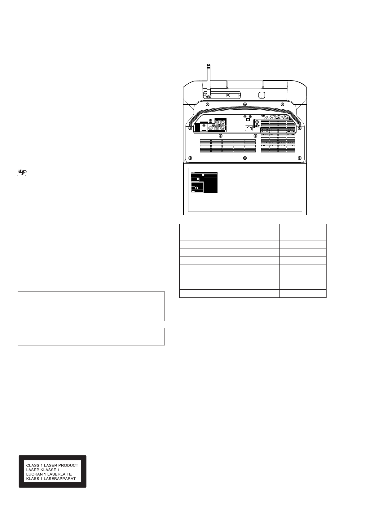
MODEL IDENTIFICATION
– Back Panel –
R
MODEL NO. / MODELO : MHC-V77DW
~ 120-240 V 50/60 Hz 220 W
Manufactured under license from Dolby
HOME AUDIO SYSTEM
Laboratories. Dolby and the double-D
symbol are trademarks of Dolby Laboratories
HECHO EN MALASIA
N0. SERIE/
0000005
NƖ SERIE
Only for Mexico / Sólo para México
Homologaciòn No: XXXXXXXXX-XXXX
Modelo: DHSR-SY30
Marca: Wistron NeWeb Corporation
Homologaciòn No: XXXXXXXXX-XXXX
Modelo: DHSR-SY25
Marca: Wistron NeWeb Corporation
NOM
NYCE
Only for Chile / Sólo para Chile
05/2016
4-595-019-01 LA9
Model Part No.
LA9
AUS
AEP, UK
E4
EA
RU
MY
TH
• Abbreviation
AUS : Australian model
E4 : African model
EA : Saudi Arabia model
LA9 : Latin-American model
MY : Malaysia model
RU : Russian model
TH : Thai model
4-595-019-0[]
4-595-019-2[]
4-595-019-3[]
4-595-019-4[]
4-595-019-6[]
4-595-019-7[]
4-595-019-8[]
4-596-414-0[]
NOTES ON LASER DIODE EMISSION CHECK
The laser beam on this model is concentrated so as to be focused
on the disc refl ective surface by the objective lens in the optical
pickup block. Therefore, when checking the laser diode emission,
observe from more than 30 cm away from the objective lens.
This appliance is classifi ed as a
CLASS 1 LASER product under
IEC 60825-1:2007. This marking
is located on the rear exterior.
4

MHC-V77DW
PLAYABLE DISCS
• AUDIO CD
• CD-R/CD-RW/DVD-R/DVD-RW
– audio data
– MP3 fi les that conforms to ISO9660 Level 1/Level 2, or
Joliet (expansion format).
Notes
• MP3 (MPEG 1 Audio Layer-3) is a standard format defi ned
by ISO (International Organization for Standardization) which
compresses audio data. MP3 fi les must be in MPEG 1 Audio
Layer-3 format.
• The system can only play back MP3 fi les that have a fi le
extension of “.mp3”.
• JIG
When disassembling the set, use the following jig (for front
panel removal).
Part No.: J-2501-238-A JIG FOR SPEAKER REMOVAL
NOTE OF REPLACING THE IC8001 AND IC8003 ON
THE 89G BOARD
IC8001 and IC8003 on the 89G board cannot exchange with
single. When these parts on the 89G board are damaged, exchange
the entire mounted board.
NOTE OF REPLACING THE IC6001, IC6002, IC6202,
IC6203, IC6341, IC6342, IC6602, IC6901 AND IC6907
ON THE BENTEN-MOTHERBOARD BOARD
IC6001, IC6002, IC6202, IC6203, IC6341, IC6342, IC6602,
IC6901 and IC6907 on the BENTEN-MOTHERBOARD board
cannot exchange with single. When these parts on the BENTENMOTHERBOARD board are damaged, exchange the entire
mounted board.
NOTE OF REPLACING THE IC8902 ON THE FMTUNER BOARD
IC8902 on the FM-TUNER board cannot exchange with single.
When this part on the FM-TUNER board is damaged, exchange
the entire mounted board.
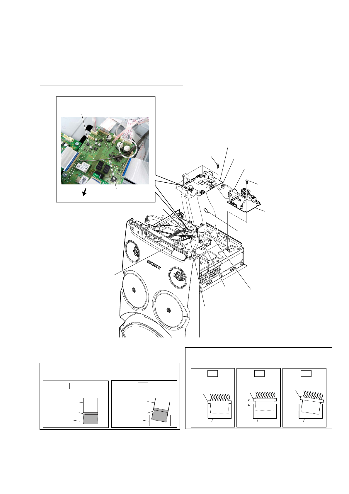
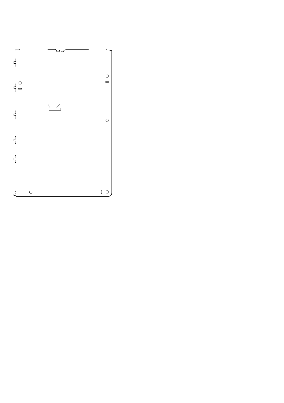
IMPORTANT NOTE OF REPLACING THE BENTENMOTHERBOARD BOARD
When the BENTEN-MOTHERBOARD board is replaced, be sure
to perform the following work.
1. Stick the new MAC address label on the rear side of this unit.
• Sticking method of MAC address label
location of MAC
address label
R
MODEL NO. / MODELO : MHC-V77DW
~ 120-240 V 50/60 Hz 220 W
Manufactured under license from Dolby
HOME AUDIO SYSTEM
Laboratories. Dolby and the double-D
symbol are trademarks of Dolby Laboratories
HECHO EN MALASIA
N0. SERIE/
0000005
NƖ SERIE
Only for Mexico / Sólo para México
Homologaciòn No: XXXXXXXXX-XXXX
Modelo: DHSR-SY30
Marca: Wistron NeWeb Corporation
Homologaciòn No: XXXXXXXXX-XXXX
Modelo: DHSR-SY25
Marca: Wistron NeWeb Corporation
NOM
NYCE
Only for Chile / Sólo para Chile
05/2016
4-595-019-01 LA9
– Rear view –
2. Perform the connection check of wireless LAN (Refer to
“CHECKING METHOD OF WIRELESS LAN CONNECTION” on this page).
3. The MAC address has been changed. Print the following
explanations, and pass it to the customer together with repaired
unit.
Note of the MAC address change:
The MAC address of this unit was changed along with this repair.
Please set it again if you are using the MAC address filtering
function of access point device connection destination.
When registration of client devices to the DLNA server device
is not automatic, it is necessary to register this unit into a server
again.
MAC address is displayed on rear side of this unit.
MAC1: MAC address of LAN(100)
MAC2: MAC address of wireless LAN
NOTE OF REPLACING THE IC001 AND IC002 ON
THE SENSOR BOARD
IC001 and IC002 on the SENSOR board cannot exchange with
single. When these parts on the SENSOR board are damaged,
exchange the entire mounted board.
NOTE OF REPLACING THE CUSHION REAR ON THE
COVER REAR ASSY
When the cover rear assy is disassembled from the set, replace the
old cushion rear on the cover rear assy with a new cushion rear.
cushion, rear
cover, rear assy
NOTE OF REPLACEMENT OF THE MS-476 BOARD
When the MS-476 board is defective, exchange the entire
LOADING COMPLETE ASSY (T).
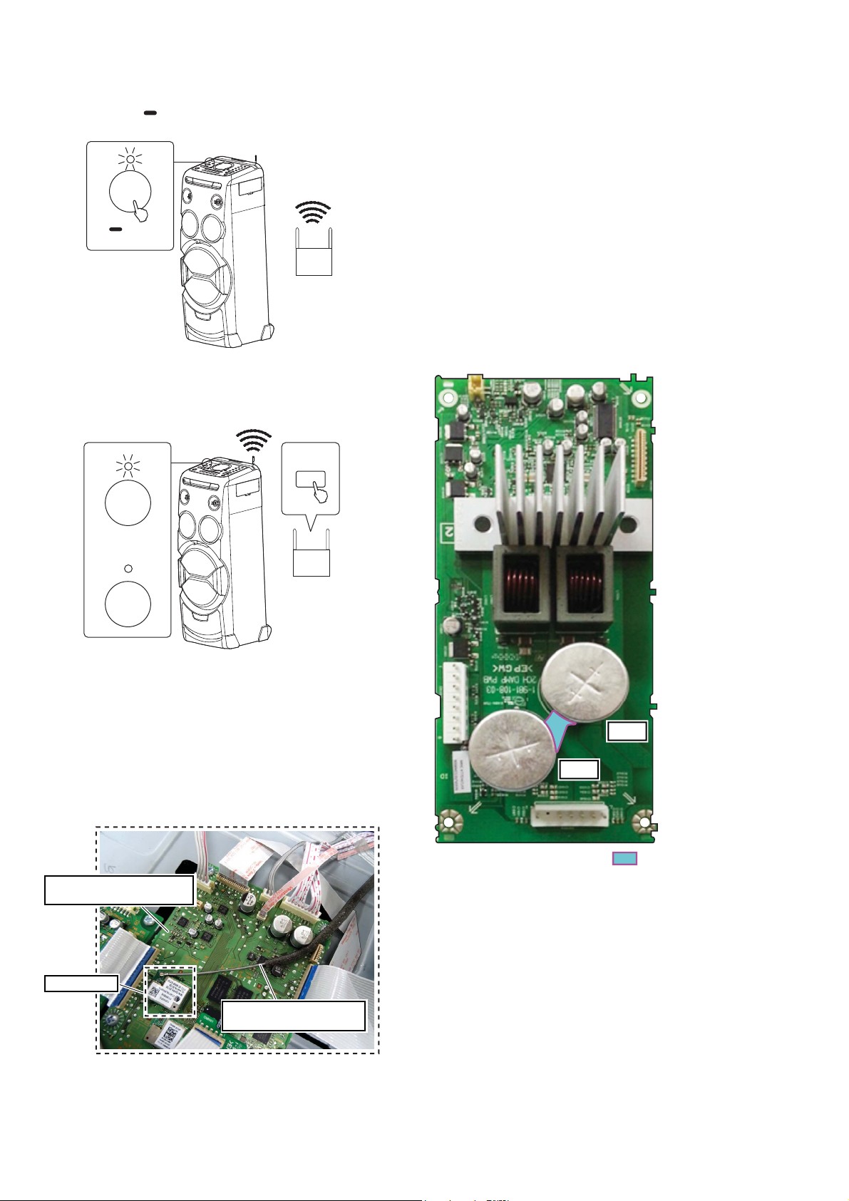
CHECKING METHOD OF WIRELESS LAN CONNECTION
When the BENTEN-MOTHERBOARD board is replaced, be sure
to perform the connection check of wireless LAN.
Required item:
• Wireless router with the Wi-Fi Protected Setup™ (WPS)
button
Procedure:
1. Press the [1] (power) button to turn on the system.
When the system is on, the power indicator lights up in green.
1
5
MHC-V77DW
2. Touch and hold WPS key on the unit until the NETWORK
indicator fl ashes in white.
NETWORK
WPS
3. Within 90 seconds, press the Wi-Fi Protected SetupTM (WPS)
button of the router.
When the NETWORK indicator lights up in white, the Wi-Fi
network connection is complete.
WPS
NETWORK
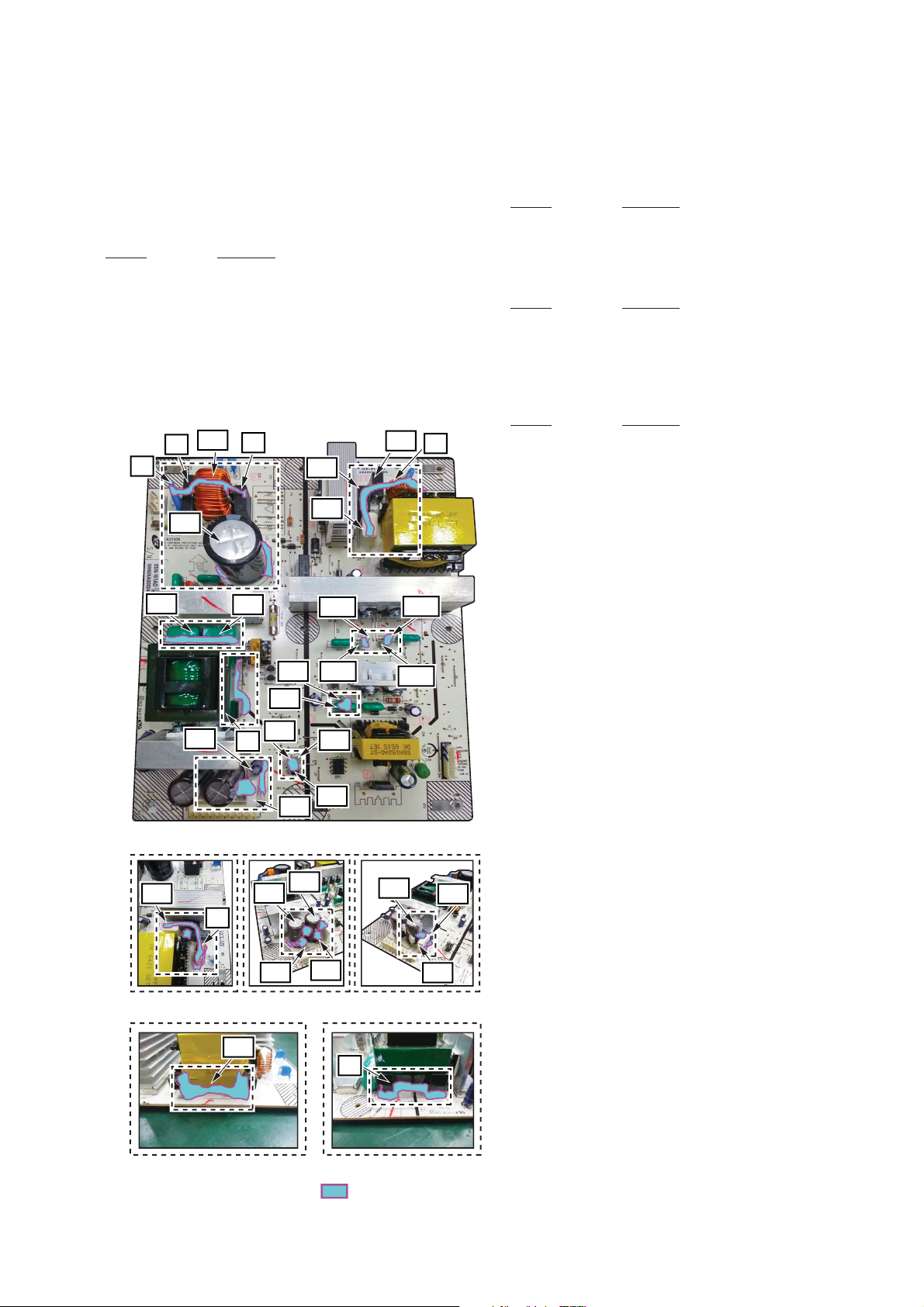
BOND FIXATION OF ELECTRIC PARTS
When 2CH DAMP board is replaced, it is necessary to fi x parts to
the boards by using a specifi ed bond without fail.
• Object boards
Complete 2CH DAMP board
• Use bond
1) SILICONE RTV ADHESIVE (UB-501G) 300ML
2) HM-40 (E318202) 300ML
• Parts position
1. 2CH DAMP board (page 6)
1. 2CH DAMP board
– 2CH DAMP Board (Component Side) –
m
NETWORK
Depending on the wireless router, press and hold the WPS button
for a few seconds. For details, refer to the operating instructions
of your router.
• The WPS button may be called “AOSS button” depending on
the wireless router.
IMPORTANT NOTE OF DHSR-SY30 AT BENTENMOTHERBOARD BOARD
Be sure to plug in the HARNESS, COAXIAL to DHSR-SY30
after replacing the BENTEN-MOTHERBOARD board.
BENTEN-MOTHERBOARD
BOARD
C1094
C1093
The portion which applies bond:
DHSR-SY30
6
HARNESS, COAXIAL
FROM ANTENNA BOARD
MHC-V77DW
BOND FIXATION OF ELECTRICAL PARTS
When switching regulator (SSN-161AD) is replaced, fi x the
electrical parts by using the bond (SC608Z2).
• Object board
1. REGULATOR, SWITCHING (SSN-161AD) board
• Use bond
Part No. Description
7-600-020-70 ADHESIVE (SC608Z2) 180ML
• Parts position
1. REGULATOR, SWITCHING (SSN-161AD) board
(page 7)
1. REGULATOR, SWITCHING (SSN-161AD) board
– SWITCHING REGULATOR (Component Side) –
Z1
C3
C27
LF1
C8
C34
R40
C17
L1
TEST DISCS
Use following TEST DISC when this unit confi rms the operation
and checks it.
• For CD
Part No. Description
3-702-101-01 DISC (YEDS-18), TEST
4-225-203-01 DISC (PATD-012), TEST
J-2501-307-A DISC (HLX-A1), TEST
• For DVD SL (Single Layer)
Part No. Description
J-6090-069-A DISC (HLX-503), TEST (NTSC)
J-6090-088-A DISC (HLX-504), TEST (NTSC)
J-2501-305-A DISC (HLX-513), TEST (NTSC)
J-6090-077-A DISC (HLX-506), TEST (PAL)
• For DVD DL (Double Layer)
Part No. Description
J-6090-071-A DISC (HLX-501), TEST (NTSC)
J-6090-089-A DISC (HLX-505), TEST (NTSC)
J-2501-306-A DISC (HLX-514), TEST (NTSC)
J-6090-078-A DISC (HLX-507), TEST (PAL)
RELEASING THE DISC TRAY LOCK
The disc tray lock function for the antitheft of sample disc in the
shop is equipped.
It can release the lock function in the following procedure.
C21
R40
C35
L1
C22
TP1
T2
C18
R50
C47
R15
R62
SR1
C20
R112
R109
R14
Q14
R47
T2
C20
R105
R107
SR1
C35
Releasing Procedure:
1. Press the [1] button to turn the power on.
2. Touch the [FUNCTION] touch key to turn the DVD/CD function.
3. Touch [x] and [MIC LEVEL +] touch keys simultaneously for
three seconds.
4. The message “UNLOCKED” is displayed on the screen
display panel and the disc tray is unlocked.
Note: When “LOCKED” is displayed on the screen display panel, the
disc tray lock is not released by turning the power on/off with the
[1] button.
IF “PROTECTX” (X IS A
NUMBER) APPEARS IN THE
DISPLAY PANEL
Immediately unplug the AC
power cord (mains lead), and
check if anything is blocking the
ventilation openings of the unit.
After you have checked and
found no problems, reconnect
the AC power cord (mains lead),
and turn on the system. If the
issue persists, contact your
nearest Sony dealer.
The portion which applies bond:
7
MHC-V77DW
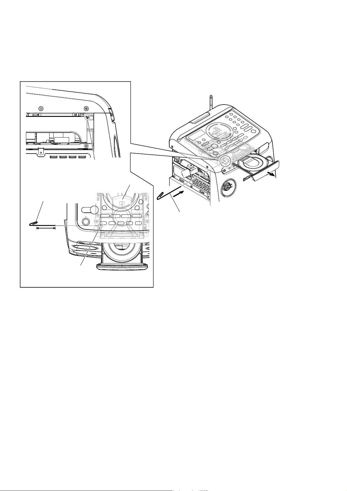
HOW TO OPEN THE TRAY WHEN POWER SWITCH TURN OFF
Note 1: After the side case and top panel block are removed, this work is done.
Note 2: Please prepare the thin wire (clip etc. processed to the length of 8 cm or more).
1 Remove the rear cover assy, side-L panel.
(Illustration of disassembly is omitted.)
– Left view –
Insert the clip etc. processed to the
length of 8 cm or more in the hole
on the side of the CDM and push.
8 cm or more
Note: Push after it inserts it
in this hole well.
hole
DVD mechanism
deck
tray
– Top view –
3
2 Insert the clip etc.
8
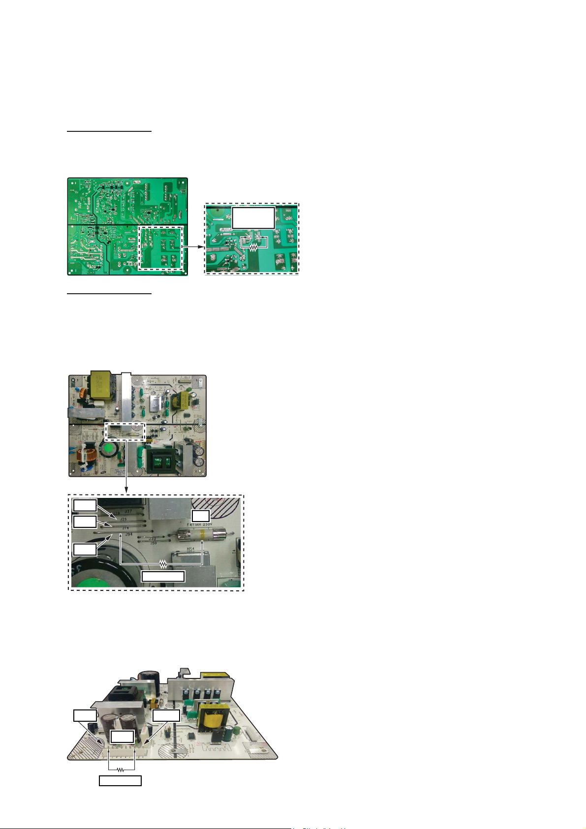
CAPACITOR ELECTRICAL DISCHARGE PROCESSING
When checking the board, for the electric shock prevention, connect the resistors to respective parts to discharge.
Discharge at capacitor (Ref. No C27)
Discharge method 1
Connect the resistors to both ends of capacitor (Ref. No. C27) on
the switching regulator (SSN-161AD) to discharge.
– SWITCHING REGULATOR (Conductor Side) –
800 :/5 W
(for C27)
Discharge method 2
When connecting the resistor to both ends of capacitor (Ref.
No. C27) on the switching regulator (SSN-161AD) is diffi cult,
discharge by connecting the resistor between fuse (Ref. No. F4)
and jumper (Ref. No. J26, J24, J94).
Note: Be careful not to short-circuit, because between the terminal is close.
MHC-V77DW
– SWITCHING REGULATOR (Component Side) –
J26
J74
J94
800 :/5 W
F4
Discharge at capacitor (Ref. No C18 and C20)
Discharge by connecting the resistor between pin 1, 2 (+VH) and
pin 8, 9 (–VH) of connector (Ref. No, CN2) on the switching
regulator board.
– SWITCHING REGULATOR Board (Component Side) –
Pin 1
Pin 10
CN2
800 :/5 W
9
MHC-V77DW
Note: Disassemble the unit in the order as shown below.
2-1. DISASSEMBLY FLOW
SET
2-2. REAR COVER ASSY
(Page 11)
2-3. SIDE-L PANEL
(Page 11)
2-4. PANEL LOADING SECTION
(Page 12)
2-5. TOP PANEL SECTION
(Page 13)
SECTION 2
DISASSEMBLY
2-6. SIDE-R PANEL
(Page 14)
2-7. CDM SECTION
(Page 15 )
2-8. CDM90-DVBU204//M
(Page 15 )
2-9. SERVICE, OPTICAL DEVICE (7G),
FLEXIBLE FLAT CABLE
(Page 16)
2-10. BACK PANEL SECTION
(Page 17)
2-11. 2CH DAMP BOARD
(Page 18)
2-13. REGULATOR, SWITCHING
(SSN-161AD)
(Page 20)
2-12. BENTEN-MOTHERBOARD BOARD,
89G BOARD
(Page 19)
10
2-14. FRONT PANEL SECTION
(Page 21)
2-15. LOUDSPEAKER (260MM)-180-11
(WOOFER) (SP5)
(Page 22)
2-16. LOUDSPEAKER
(120MM)-181-11
(MID: L-CH) (SP1),
LOUDSPEAKER
(120MM)-181-11
(MID: R-CH) (SP3)
(Page 22)
Note: Follow the disassembly procedure in the numerical order given.
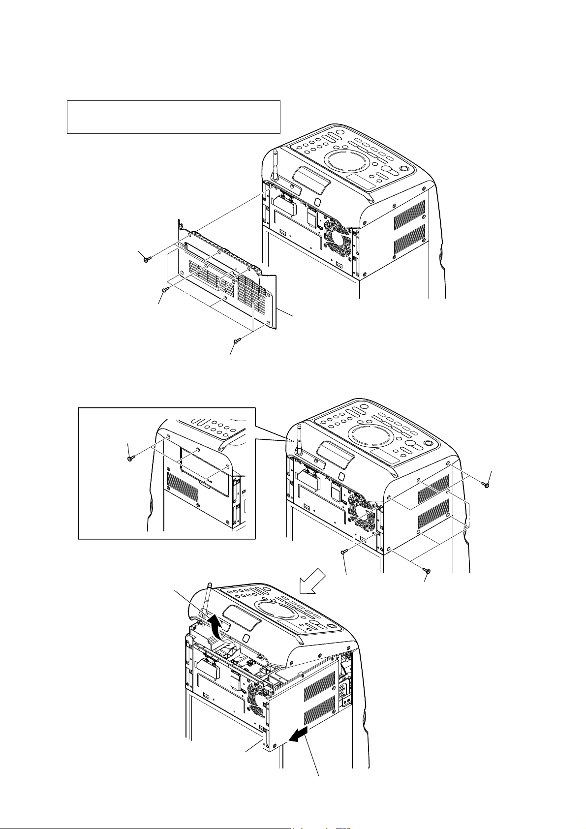
2-2. REAR COVER ASSY
Note 1: When the cover rear assy is disassembled from the
set, refer “NOTE OF REPLACING THE CUSHION
REAR ON THE COVER REAR ASSY” on page 5.
1 three screws
(flathead (TP))
MHC-V77DW
2 three screws
(+BVTP 3 u 10)
2-3. SIDE-L PANEL
3 three screws
(flathead (TP))
4 Lift up the top panel section
in the direction of the arrow.
2 five screws
(+BVTP 3 u 10)
3 cover, rear assy
Note 2: There is cushion rear at the top of the cover, rear assy.
Remove the cover, rear assy gently to avoid from
being broken.
2 three screws
(flathead (TP))
1 two screws
(+BVTP 3 u 8)
2 four screws
(flathead (TP))
6 panel side, L
5 Slide the panel side, L
in the direction of the arrow.
11

MHC-V77DW
2-4. PANEL LOADING SECTION
3 three claws
4 panel loading
section
– Left view –
Insert the clip etc. processed to the
length of 8 cm or more in the hole
on the side of the CDM and push.
8 cm or more
Note: Push after it inserts it
in this hole well.
hole
DVD mechanism
deck
2 Draw out the tray.
1 Insert the clip etc.
tray
– Top view –
12
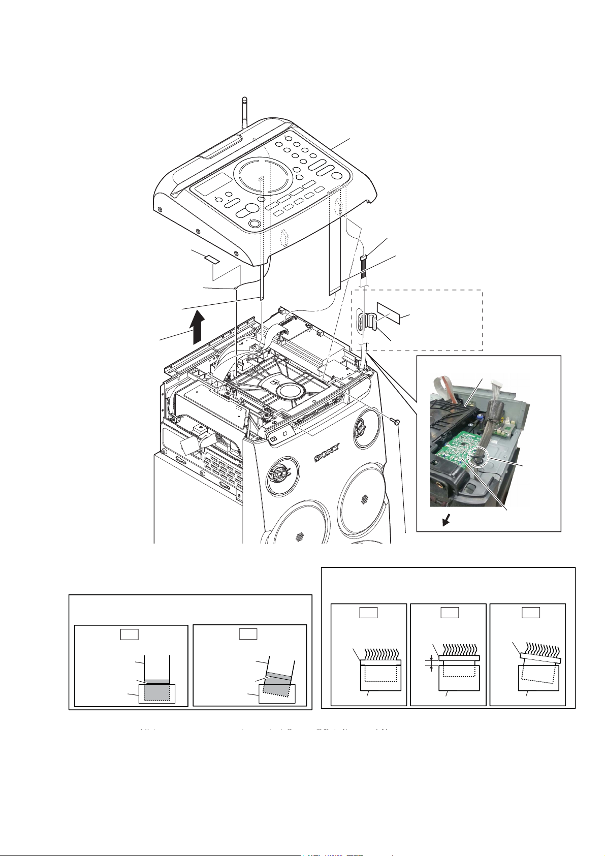
2-5. TOP PANEL SECTION
3 filament tape
4 dual-band dipole
antenna connector
6 wire (flat type)
(7 core) (CN6203)
MHC-V77DW
0 panel, top section
9 CN1009 (8P)
5 wire (flat type)
(29 core) (CN3902)
$(38.580<$86
7 cushion, seal
2 Remove the
panel, top section
in the direction
of the arrow.
Note 1: When installing the wire (flat type), ensure that
the colored line is not slanted after insertion.
OK
Insert is straight to the interior. Insert is incline
wire (flat type) wire (flat type)
NG
8 clamp, sleeve ferrite
:LUHVHWWLQJ
CDM section
pin, lead
front side
1 two screws
(flathead (TP))
Note 2: When you install the connector, please install them correctly.
There is a possibility that this machine damages when not
correctly installing it.
OK NG NG
Insert is straight
to the interior.
connector
Insert is shallow
connector
MIC board
Insert is incline
connector
colored line
colored line
connectorconnector
connector
connector connector
13

MHC-V77DW
2-6. SIDE-R PANEL
4 wire (flat type)
(29 core) (CN6850)
3 one screw
(+BVTP 3 u 8)
7 panel, side-R section
1 two screws
(+BVTP 3 u 8)
6 Remove the
panel, side-R
in the direction
of the arrow.
Note 1: When installing the wire (flat type), ensure that
the colored line is not slanted after insertion.
OK
Insert is straight to the interior. Insert is incline
wire (flat type) wire (flat type)
colored line
colored line
connectorconnector
NG
5 CN6801 (4P)
2 two screws
2 two screws
(flathead (TP))
Note 2: When you install the connector, please install them correctly.
There is a possibility that this machine damages when not
correctly installing it.
OK NG NG
Insert is straight
to the interior.
connector
connector
Insert is shallow
connector
(flathead (TP))
Insert is incline
connector
connector connector
14
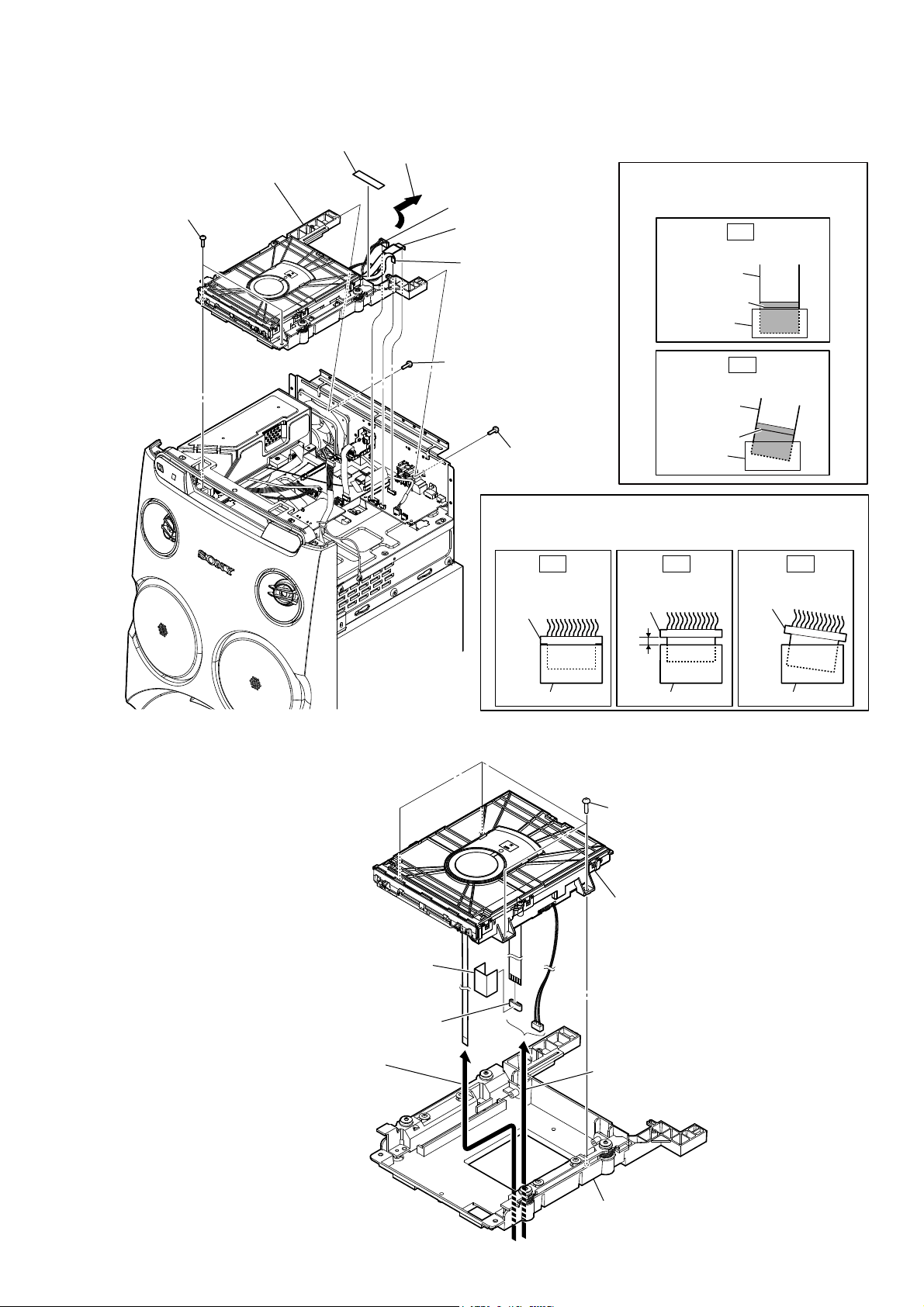
2-7. CDM SECTION
8 CDM block
1 two screws
(+BVTP 3 u 8)
3 filament tape
7 Remove the CDM section
in the direction of the arrow.
6 CN8400 (6P)
4 flexible flat cable
(24 core) (CN8001)
5 flexible flat cable
(5 core) (CN8401)
MHC-V77DW
Note 1: When installing the flexible flat
cable, ensure that the colored line
is not slanted after insertion.
OK
Insert is straight to the interior.
flexible flat
cable
colored line
connector
2-8. CDM90-DVBU204//M
2 one screw
(+BVTP 3 u 8)
flexible flat
cable
colored line
2 one screw
(+BVTP 3 u 8)
Note 2: When you install the connector, please install them correctly.
There is a possibility that this machine damages when not
correctly installing it.
OK NG NG
Insert is straight
to the interior.
connector
connector
connector
1 four screws
(BVTP3 u 8)
connector
Insert is shallow
connector connector
NG
Insert is incline
Insert is incline
connector
4 cushion, saranet (30X50)
5 core, ferrite
2 Draw wire out of
the hole in bracket CDM
section.
7 CDM90-DVBU204//M
3 Draw two wires out of
the hole in bracket CDM
section.
6 bracket CDM section
15

MHC-V77DW
2-9. SERVICE, OPTICAL DEVICE (7G), FLEXIBLE FLAT CABLE
2 chuck holder assy (T)
1 six claws
qa insulator
8 four insulator screws
qs service,
optical device (7G)
qa insulator
qa insulator
6 belt
3 Insert the thin
wire (clip etc.).
qd loading base assy
4
5 tray
,QVWDOODWLRQRIIOH[LEOHIODWFDEOH3DQGIOH[LEOHIODWFDEOH3
Note: This illustration sees the loading assy (T) from bottom side.
5 two claws
1 flexible flat cable (24P)
loading assy (T)
0
9
7 connector
qf filament tape
5 three claws
qh flexible flat cable
(5P)
qj holder, FFC
qk flexible flat cable
(24P)
qg
loading assy (T)
– Bottom view –
16
terminal face
2 Through the hole
Under the guide
(Fold area)
3 Through the hole
6 holder, FFC
4
7 flexible flat cable
(24P)
9 filament tape
8 flexible flat cable
(5P)
Under the guide
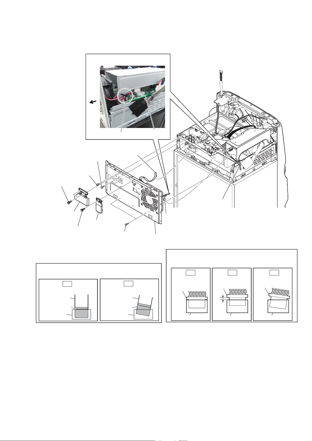
2-10. BACK PANEL SECTION
:LUHVHWWLQJ
rear
side
0 wire (flat type)
6 two screws
(+BVTP 3 u 8)
(9 core) (CN6402)
2CH DAMP board
clamp
MHC-V77DW
5 one screw
1 two screws
(rivet (DIA. 3), nylon)
Note 1: When installing the wire (flat type), ensure that
the colored line is not slanted after insertion.
Insert is straight to the interior. Insert is incline
wire (flat type) wire (flat type)
(+B 3 u 6)
2 cover, jack
3 one screw
(rivet (DIA. 3), nylon)
OK
colored line
4 cover, LAN
7 two screws
(+BVTP 3 u 8)
NG
colored line
connectorconnector
8 Wire is removed
from the clamp.
9 CN1002 (2P)
qa panel, back section
Note 2: When you install the connector, please install them correctly.
There is a possibility that this machine damages when not
correctly installing it.
OK NG NG
Insert is straight
to the interior.
connector
connector
–7RSUHDUYLHZ–
Insert is shallow
connector
connector connector
connector
Insert is incline
17

MHC-V77DW
2-11. 2CH DAMP BOARD
7 one screw
(+BVTP 3 u 8)
:LUHVHWWLQJ
2CH DAMP board
9 plate, shield D-AMP
qa heat sink, AMP
$(38.58
0<$86
4 cushion, seal
5 core, ferrite
3 CN1004 (8P)
8 clamp
qs sheet, thermal
6 CN1003
(6P)
7 three screws
(+BVTP 3 u 8)
0 two screws
(+PTPWH 2.6 u L (DIA8.0)
qd 2CH DAMP board
qf two screws
(+BVTP 3 u 8)
qh bracket, heat sink
qg Remove the
bracket, heat sink
in the direction
of the arrow.
2 Wire is removed
from the clamp.
1 wire (flat type)
(17 core) (CN1001)
rear
side
clampcushion (QJ, S)
Note 1: When installing the wire (flat type), ensure that
the colored line is not slanted after insertion.
OK
Insert is straight to the interior. Insert is incline
wire (flat type) wire (flat type)
colored line
colored line
connectorconnector
NG
Note 2: When you install the connector, please install them correctly.
There is a possibility that this machine damages when not
correctly installing it.
OK NG NG
Insert is straight
to the interior.
connector
connector
Insert is shallow
connector
connector connector
connector
Insert is incline
18
2-12. BENTEN-MOTHERBOARD BOARD, 89G BOARD
Note 1: When the BENTEN-MOTHERBOARD board is replaced,
refer to “IMPORTANT NOTE OF REPLACING THE
BENTEN-MOTHERBOARD BOARD” on page 5 and “IMPORTANT NOTE OF DHSR-SY30 AT BENTEN-MOTHERBOARD BOARD” on page 6.
:LUHVHWWLQJ
BENTEN-MOTHERBOARD board
MHC-V77DW
ANTENNA board
rear side
5 wire (flat type)
(6 core) (CN6202)
harness coaxial connector
6 CN6901 (9P)
9 four screws
(+BVTP 3 u 8)
7 CN6851 (3P)
0 BENTEN-MOTHERBOARD board
4 CN6802 (3P)
8 wire (flat type)
(29 core) (CN7001)
qa two screws
(+BVTP 3 u 8)
qs 89G board
2 filament tape
1 CN6401
(4P)
3 ANTENNA board
harness coaxial connector
Note 2: When installing the wire (flat type), ensure that
the colored line is not slanted after insertion.
OK
Insert is straight to the interior. Insert is incline
wire (flat type) wire (flat type)
colored line
colored line
connectorconnector
NG
Note 3: When you install the connector, please install them correctly.
There is a possibility that this machine damages when not
correctly installing it.
OK NG NG
Insert is straight
to the interior.
connector
connector
Insert is shallow
connector
connector connector
connector
Insert is incline
19

MHC-V77DW
2-13. REGULATOR, SWITCHING (SSN-161AD)
3 one screw
(+BVTP 3 u 8)
6 eight screws
(+PWH 3 u 8 (SUMITITE))
qa Remove the wire from the hole.
:LUHVHWWLQJ
REGULATOR, SWITCHING
hole
(SSN-161AD)
qd two step screws
M4
rear
side
4 clamp
2 two screws
(+BVTP 3 u 8)
5 sub, chassis
E
7 clamp
:LUHVHWWLQJ
REGULATOR, SWITCHING
(SSN-161AD)
2 three screws
(+BVTP 3 u 8)
6 one screw
(+PWH 3 u 8
(SUMITITE))
clamp
qs REGULATOR, SWITCHING
(SSN-161AD)
9 himelon 45
0 core, ferrite
8 CN1
qd two step screws
M4
qf chassis block
E
Note : When you install the connector, please install them correctly.
There is a possibility that this machine damages when not
correctly installing it.
OK NG NG
Insert is straight
to the interior.
connector
Insert is shallow
connector
1 one screw
(+BVTP 3 u 8)
Insert is incline
connector
20
connector
connector connector
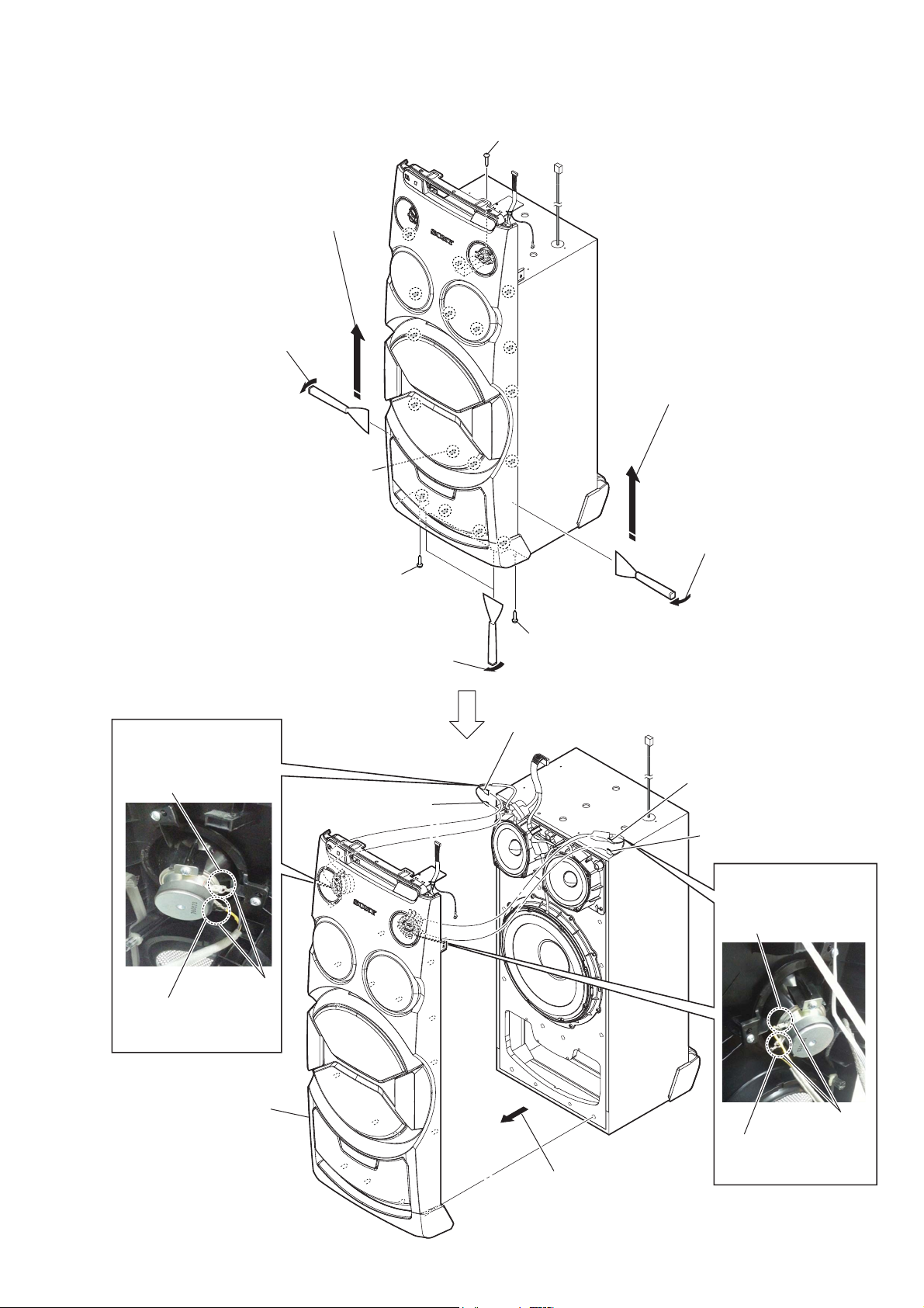
2-14. FRONT PANEL SECTION
4 All bosses are removed while moving
jig in the direction of the arrow, and
panel, front section is removed.
3 Insert the jig into a space and slowly
remove the panel, front section.
Note 1: When using a jig, please work
so as not to injure panel, front
section and speaker cabinet.
total seventeen bosses
MHC-V77DW
1 one screw
(4 x 13) (TR-184A)
4 All bosses are removed while moving
jig in the direction of the arrow, and
panel, front section is removed.
3 Insert the jig into a space and slowly
remove the panel, front section.
Note 1: When using a jig, please work
so as not to injure panel, front
section and speaker cabinet.
:LUHVHWWLQJ
Push the protrusion, and
remove the terminal
(wide side)
2 one screw
(4 x 13) (TR-184A)
6 terminal (narrow)
[yellow]
3 Insert the jig into a space and slowly
remove the panel, front section.
Note 1: When using a jig, please work
so as not to injure panel, front
section and speaker cabinet.
2 one screw
(4 x 13) (TR-184A)
6 terminal (wide side)
[black/yellow]
6 terminal (narrow)
[yellow]
6 terminal (wide side)
[black/yellow]
:LUHVHWWLQJ
Push the protrusion, and
remove the terminal
(narrow side)
protrusion
Push the protrusion, and
remove the terminal
(narrow side)
7 panel,
front section
5 Remove the
panel, front section
in the direction of an arrow.
protrusion
Push the protrusion, and
remove the terminal
(wide side)
21

MHC-V77DW
2-15. LOUDSPEAKER (260MM)-180-11 (WOOFER) (SP5)
:LUHVHWWLQJ
Push the protrusion, and
remove the terminal (wide side)
+RZWRLQVWDOOWKHORXGVSHDNHU
PP63
loudspeaker
terminal position
(260mm)-180-11 (SP5)
Push the protrusion, and
remove the terminal (narrow side)
4 loudspeaker
(260mm)-180-11
(woofer) (SP5)
protrusion
3 terminal (narrow)
[grey/black]
3 terminal
(wide side) [grey]
1 eight screws
((1) (4 u 20), +BV TAPPING)
2-16. LOUDSPEAKER (120MM)-181-11 (MID: L-CH) (SP1),
LOUDSPEAKER (120MM)-181-11 (MID: R-CH) (SP3)
3 terminal (narrow)
[blue/black]
+RZWRLQVWDOOWKHORXGVSHDNHU
PP6363
terminal position
loudspeaker
(120mm)-181-11 (SP1)
loudspeaker
(120mm)-181-11 (SP3)
2 Remove the loudspeaker
(120mm)-181-11 (SP1)
in the direction of the arrow.
4 loudspeaker
(120mm)-181-11
(mid: L-ch)
(SP1)
2 Remove the loudspeaker (260mm)-180-11
(SP5) in the direction of the arrow.
7 terminal (narrow)
3 terminal
(wide side) [blue]
[red/black]
7 terminal
(wide side)
[red]
22
1 four screws
((1) (3.5X14), TAPPING)
5 four screws
((1) (3.5X14),
TAPPING)
8 loudspeaker (120mm)-181-11
(mid: R-ch) (SP3)
6 Remove the loudspeaker (120mm)-181-11
(SP3) in the direction of the arrow.
SECTION 3
TEST MODE
MHC-V77DW
[PANEL TEST MODE]
This mode is used to check the screen display panel, LEDs, keys,
GESTURE CONTROL sensor, model, destination, motion gesture
and software version.
Procedure:
1. Touch [] and [
TUNING
‒ .] touch keys simultaneously
and hold 3 seconds.
2. All LEDs and segments in screen display panel are lighted up.
3. When you want to enter to the software version display mode,
touch [+] touch key.
The model information appears on the screen display panel.
Touch [+] touch key again to view the destination
information.
4. During the destination information display, touch [+] touch
key. Each time [+] touch key is touched, the screen display
panel shows the version of each category software in the
following sequence: SYSTEM, MTK and return back to model
information display.
5. Touch [‒] touch key, the key check mode is activated.
6. In the key check mode, the screen display panel displays
“K 0 ”.
Each time a button/touch key is touched, “K” value increases.
However, once a button/touch key has been touched, it is no
longer taken into account.
The screen display panel displays “<” or “>” or “˄” or “˅” on
the right side of “K31 OK” each time swing left, right, up and
down at GESTURE CONTROL.
7. To release from this mode, touch the touch keys in the same
manner as step 1, or disconnect the power cord.
[COLD RESET]
The cold reset clears all data including preset data stored in the
data flash to initial conditions. Execute this mode when returning
the set to the customer.
Procedure:
1. Press the [1] button to turn the power on.
2. Touch [] and [
TUNING + >]
touch keys simultaneously
for 3 seconds.
3. “COLD RST” appears on the screen display panel. After that,
the screen display panel will display “WELCOME”. The set
will automatically return to SONY DEMO condition.
[DISC THEFT PREVENTION]
This mode let you lock the disc tray. When this mode is activated,
the disc tray will not open when [Z] touch key is touched. The
message “LOCKED” will be displayed on the screen display
panel. This mode only applied when there is disc on the tray.
Procedure:
1. Press the [1] button to turn the power on.
2. Touch the [FUNCTION] touch key to select the DVD/CD
function.
3. Touch the [Z] touch key to open the disc tray and insert the
CD.
4. Touch the [Z] touch key to close the disc tray.
5. Touch [x] and [MIC LEVEL +] touch keys simultaneously for
5 seconds.
6. The message “LOCKED” is displayed on the screen display
panel and the disc tray is locked.
(Even if pressing the [Z] touch key, the message “LOCKED”
is displayed on the screen display panel and the disc tray is
locked)
[DEMO MODE]
The demo mode can be performed.
(This mode is used by shop front)
Procedure:
1. Press the [
1] button to turn the system.
2. Touch [] and [SOUND FIELD] touch keys simultaneously
for 5 seconds.
3. The message “AutoPLAY” is displayed on the screen display
panel.
4. Touch [TUNING + >] or [TUNING – .] to select either
AutoPLAY or AutoSTOP in Demo mode, then touch [N] to
make selection.
5. Touch [TUNING + >] or [TUNING – .] to select reset
timer setting, then touch [N] to make selection.
6. Set will power off and power on, after that it will mode into
Demo mode.
7. The message “* DEMO *” is displayed on the screen display
panel.
• To release from Demo Mode
1. Touch [] and [SOUND FIELD] touch keys simultaneously
for 5 seconds.
Note: The demo mode does not release by unplug the AC cord.
[BROWSER MODE]
Prepare PC or Mobile Phone that is able to connect WiFi. Turn off
proxy server setting.
• Procedure on the set
1. Perform COLD RESET.
2. Press [1] button to turn on the system.
3. Touch [B] and [SOUND FIELD] touch keys simultaneously
for 5 seconds to enter Browser Mode.
4. The message “BROWSER” is displayed on the screen display
panel.
• Procedure on the PC/Mobile Phone
In order to connect the set to WIFI, the following standard
procedure must be followed.
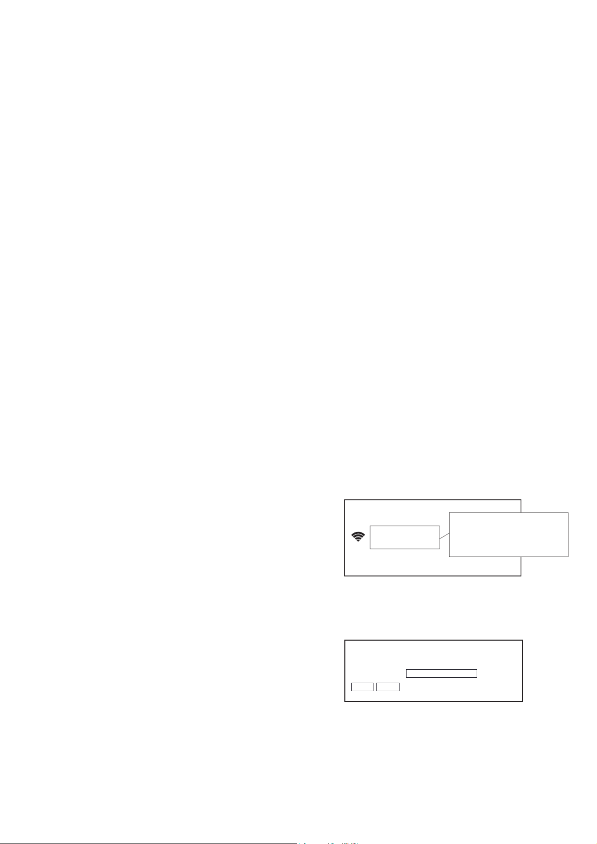
1. Connect the set by soft AP and select the following:
Wi-Fi networks
SSID: MHC-V77DW_XXXXXX
MHC-V77DW_3e2511
Saved
XXXXXX : Lower 6 digits of MAC Address
Key : None(Non Secure)
(Display image is example of procedure on the Mobile Phone)
2. Access to [http://192.168.211.161/cgi-bin/index_fact.cgi] on
the browser of PC or Mobile Phone and below image will
appear.
Set Serial No. and Color variation
Login Password
Send(P) Reset(R)
Releasing method:
1. Touch [x] and [MIC LEVEL +] touch keys simultaneously for
5 seconds.
2. The message “UNLOCKED” is displayed on the screen
display panel and the disc tray is unlocked.
23
MHC-V77DW
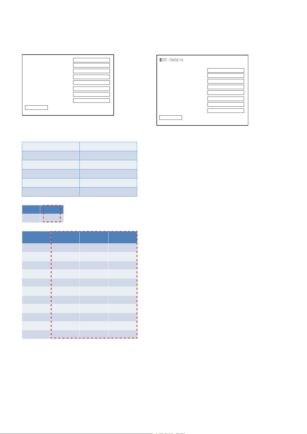
3. Insert password (svctm) and click [Send(P)]. The following
image will appear.
(Displayed values in the following fi gure are example)
Serial No.
Color Variation
Wifi Channel Index
Wifi Power Table
Destination
Wired LAN MAC Address
Wireless LAN MAC Address
BD Address
Write and Copy(C)
8388828
00
06
1
30
104fa8471c95
8c579b15f48f
8c579b15f490
4. Insert the value for Serial No. (7 digits), Color Variation, Wifi
Channel Index, Wifi Power Table, Destination and Wired
LAN MAC Address respectively by referring below data.
Serial No. (7 digits) Input 7 digits directly
Color Variation Input 2 digits directly
Wifi Channel Index Input 2 digits directly
Wifi Power Table Input 1 digit directly
Destination Input 2 digits directly
Wired LAN MAC Address Input 12 digits directly
Color Number
Black 0
Destination Destination
AR2 25 3 3
LA9
CEK 27 0 4
CEL 28 0 4
RU1 29 6 4
E4 30 6 4
EA3 31 6 4
E12 32 0 4
TH1 33 0 4
AU1 34 0 4
SP6 10 0 4
Index
26 5 3
Wi-Fi Channel
Index
Wi-Fi Power
Table
6. If you enter non-specifi ed number of digits and click the
button, then an ERR message is displayed.
(Displayed values in the following fi gure are example)
ERR : Serial no
Serial No.
Color Variation
Wifi Channel Index
Wifi Power Table
Destination
Wired LAN MAC Address
Wireless LAN MAC Address
BD Address
Write and Copy(C)
8388828
00
06
1
30
104fa8471c95
8c579b15f48f
8c579b15f490
7. To save the value, press [1] button.
[DVD COLOR SYSTEM MODE] (Except for Latin American,
European, and Russian models)
• This mode let you change the color system of the video output
from PAL to NTSC or vice-versa.
Procedure:
1. Press the [1] button to turn on the system.
2. Touch the [FUNCTION] touch key until message “DVD/CD”
appears.
3. Touch the [DJ] and [
TUNING +
>] touch keys simultane-
ously and hold for 3 seconds.
4. The message “PAL” or “NTSC” appears on the screen display
panel.
• To release from DVD Color System Mode
1. Once the color system has been selected, the mode is fi xed
there after. If you wish to change the mode again, perform
step 3 again.
5. Click [Write and Copy(C)] to rewrite the values and refresh
the screen.
24
SECTION 4
ELECTRICAL CHECK
MHC-V77DW
TUNER SECTION
0 dB = 1 ȝV
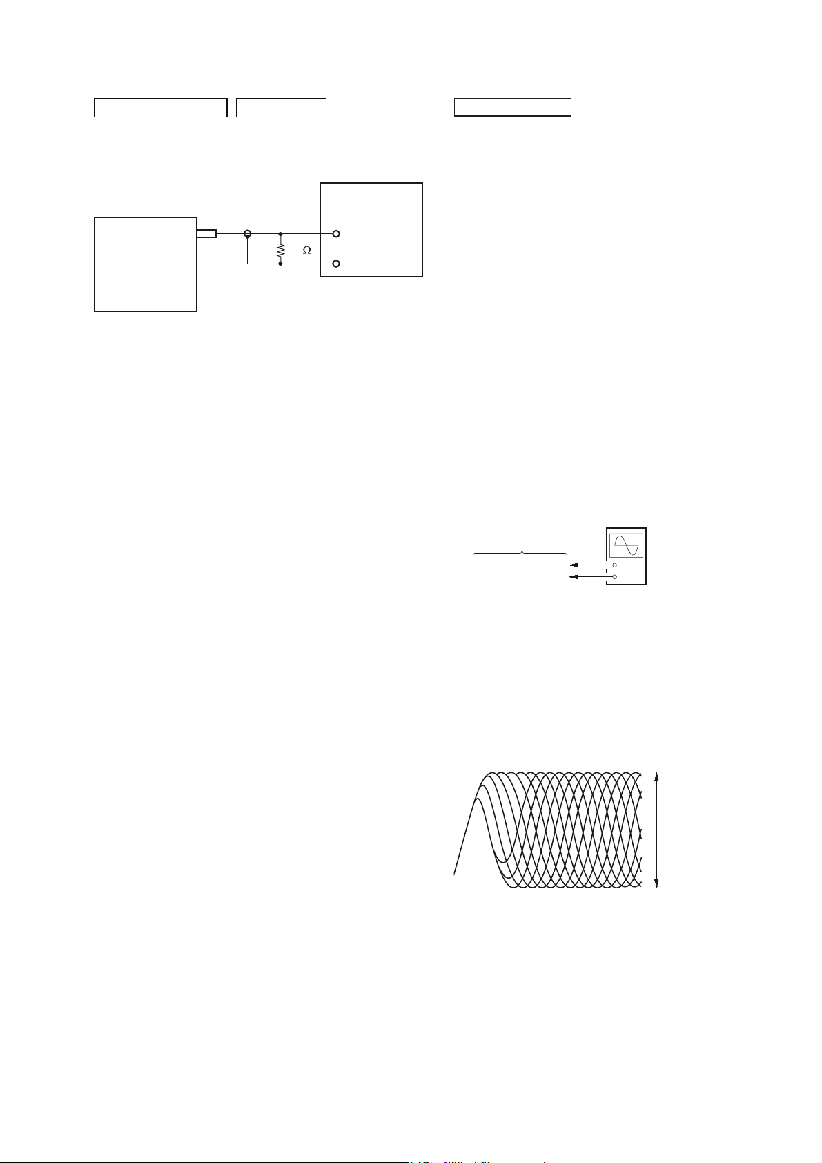
FM AUTO STOP CHECK
signal
generator
set
+
75
–
Procedure:
1. Turn the power on.
2. Input the following signal from Signal Generator to FM
antenna input directly.
Carrier frequency : A = 87.5 MHz, B = 98 MHz, C = 108 MHz
Deviation : 75 kHz
Modulation : 1 kHz
ANT input : 35 dBu (EMF)
Note: Please use 75 ohm “coaxial cable” to connect SG and the
set. You cannot use video cable for checking.
Please use SG whose output impedance is 75 ohm.
3. Set to FM tuner function and scan the input FM signal with
automatic scanning.
4. Confi rm that input Frequency of A, B and C detected and
automatic scanning stops.
The stop of automatic scanning means “The station signal is
received in good condition”.
CD/DVD SECTION
[TEST DISC LIST]
Use the following test disc on test mode.
• CD: YEDS-18 (PART No. 3-702-101-01)
or
PATD-012 (PART No. 4-225-203-01)
HLX-A1 (PART No. J-2501-307-A)
• DVD (SL)
NTSC HLX-503 (PART No. J-6090-069-A)
or
HLX-504 (PART No. J-6090-088-A)
HLX-513 (PART No. J-2501-305-A)
PAL HLX-506 (PART No. J-6090-077-A)
• DVD (DL)
NTSC HLX-501 (PART No. J-6090-071-A)
or
HLX-505 (PART No. J-6090-089-A)
HLX-514 (PART No. J-2501-306-A)
PAL HLX-507 (PART No. J-6090-078-A)
Note: When the BASE UNIT is replaced, perform the Execute
IOP measurement
(Refer to page 23).
FOCUS BIAS CHECK
oscilloscope
(DC range)
MOTHERBOARD board
CN302 pin 17 (RF)
CN302 pin 1 (GND)
+
–
Procedure:
1. Connect the oscilloscope to CN302 pin 17 (RF) and CN302
pin 1 (GND) on the MOTHERBOARD board.
2. Press the [
] button to turn the power on, and press the
?/1
[FUNCTION] button to select DVD/CD function.
3. Set the test disc (CD: YEDS-18) on the tray and press [N]
button to playback.
4. Confi rm that oscilloscope waveform is as shown in the fi gure
below (eye pattern).
A good eye pattern means that the diamond shape () in the
center of the waveform can be clearly distinguished.
VOLT/DIV: 200 mV
TIME/DIV: 500 ns
level:
1.1 ± 0.25 Vp-p (DVDSL)
1.0 ± 0.25 Vp-p (CD)
25
MHC-V77DW
Checking Location:
-MOTHERBOARD Board (COMPONENT SIDE)-
pin 17 (RF)pin 1 (GND)
CN302
26

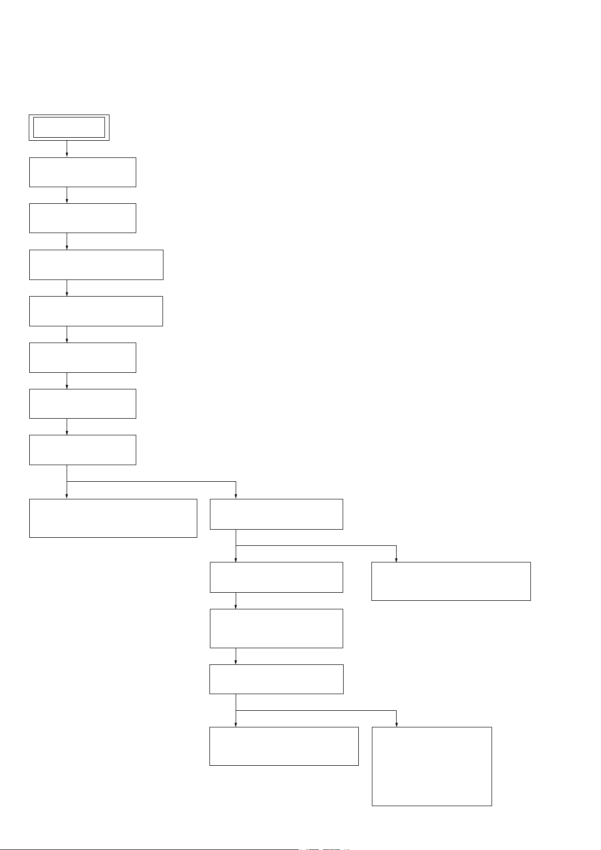
TROUBLESHOOTING
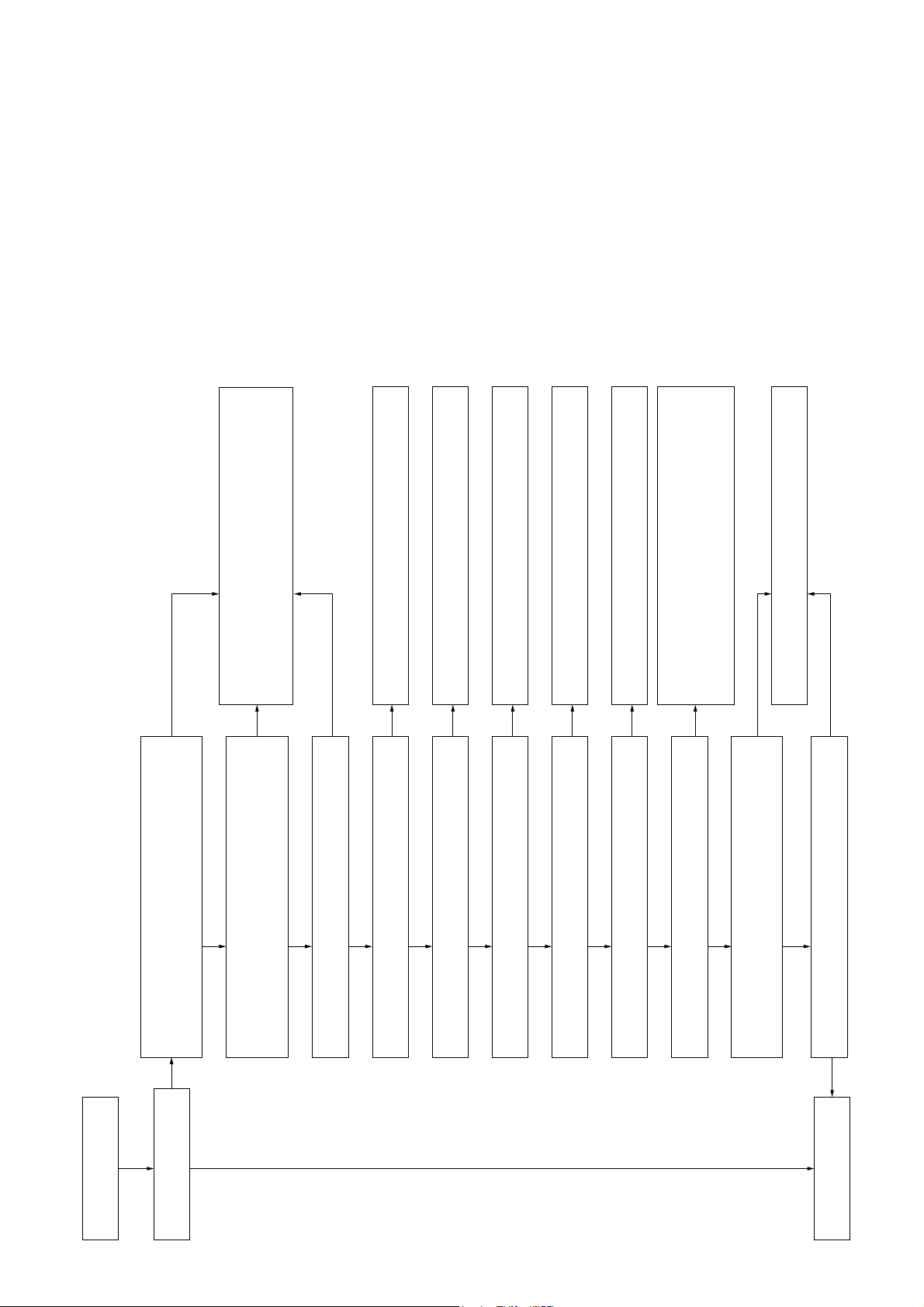
Switching Regulator (SSN-161AD) Diagnosis Flow
Connect the AC power cord.
MHC-V77DW
SECTION 5
The output voltage from the switching regulator is the following standard value.
Standby Demo mode Power on
CN4:
Between pin 3, 4 (LED)
and pin 5, 6 (LED GND)
CN2:
Between pin 1 to 2 (+PVDD)
and pin 5 (GND)
CN2:
%HWZHHQSLQWRí39''
and pin 5 (GND)
CN2:
Between pin 3 (+VL)
and pin 5 (GND)
CN2:
%HWZHHQSLQí9/
and pin 5 (GND)
CN2:
Between pin 10 (SVP)
and pin 5 (GND)
Yes
End
(1) CN1 (AC power cord connector)
13.5 V ± 5 % 13.5 V ± 5 % 13.5 V ± 5 %
0 V
0 V 0 V í9
0 V 0 V 17 V ± 5 %
0 V 0 V í9
0 V 0 V í9
0 V 62.5 V ± 5 %
– SWITCHING REGULATOR (Component Side) –
(2) F1 (Fuse)
(3) T1 (Sub power transformer)
(4) CN4 (Main power connector)
Pin 1 : Audio
Pin 2 : Audio GND
(6)
Pin 3 : LED
Pin 4 : LED
Pin 5 : LED GND
Pin 6 : LED GND
Pin 7 : AC-DET
Pin 8 : PCON
Pin 9 : LOW AC
(5) T2 (Main power transformer)
(6) CN2 (Amplifier power connector)
Pin 1 : +PVDD
Pin 2 : +PVDD
Pin 3 : +VL
Pin 4 : GND
– SWITCHING REGULATOR (Conductor Side) –
Pin 5 : GND
Pin 6 : GND
Pin 1
Pin 7 : –VL
Pin 8 : –PVDD
Pin 9 : –PVDD
Pin 10 : SPV
(6)
No
Replace the switching regulator.
(5)
(3)
(4)
(2)
(1)
Pin 10
(4)
Pin 9 Pin 1
27
MHC-V77DW
Reinsert the wire that connected between CN1004 on the
2CH DAMP board and switching regulator, and check the
voltage again.
If there is no problem to the wire, check that the switching
regulator is properly fixed.
No
The voltage between pin 7 to 8 (+VH) and pin 5 (PGND) of
CN1004 on the 2CH DAMP board is +62.5 V.
7KHYROWDJHEHWZHHQSLQWRí9+DQGSLQ3*1'RI
&1RQWKH&+'$03ERDUGLVí9
No
No
Yes
The voltage between pin 6 (+VL) and pin 5 (PGND) of
CN1004 on the 2CH DAMP board is +17 V.
7KHYROWDJHEHWZHHQSLQí9/DQGSLQ3*1'RI
No
Yes
&1RQWKH&+'$03ERDUGLVí9
The voltage between pin 1 (-VG) and pin 5 (PGND) of
Checks circumference circuit of REG IC1001.
If there are no problems, exchanges IC1001.
No
Yes
CN1004 on the 2CH DAMP board is -45.5 V.
Yes
Checks OUT terminal REG IC1001 output is -50.5 V
reference to pin 5 (PGND) of CN1004.
Reinsert the flexible flat cable (FFC4) that connected between
CN1001 on the 2CH DAMP board and CN6404 on the
MOTHERBOARD board, and check the voltage again.
If there is no problem to the flexible flat cable (FFC4), check
Checks circumference circuit of REG IC1002.
If there are no problems, exchanges IC1002.
No
Checks OUT terminal REG IC1002 output is +7 V reference
to pin 5 (PGND) of CN1004.
Checks circumference circuit of REG IC1003.
If there are no problems, exchanges IC1003.
No
Yes
Checks OUT terminal REG IC1003 output is -7 V reference
to pin 5 (PGND) of CN1004.
Checks circumference circuit of REG IC1006.
If there are no problems, exchanges IC1006.
Checks circumference circuit of REG IC1007.
If there are no problems, exchanges IC1007.
No
Yes
Checks OUT terminal REG IC1006 output is +9 V reference
to pin 5 (PGND) of CN1004.
No
Yes
Yes
Checks OUT terminal REG IC1007 output is +15 V reference
to pin 5 (PGND) of CN1004.
that the MOTHERBOARD board is properly fixed.
No
Yes
Check the voltage of CN1001 pin 7 (I_AMP_RESET) on the
2CH DAMP board is +3.3 V.
Replace 2CH DAMP Board.
No
Leave 2CH DAMP Mount to a state of it only and checks
Power Audio Driver (MOSFET) with Tester.
Is it shorted out? (Refer to Page 29)
No
Yes
Assembles into the unit again then, checks whether there is
audio output from 2CH DAMP Board.
Yes
Yes
Playback the music.
2CH DAMP Board Mount Diagnosis Flow
Yes
The audio is outputted
from the 2CH DAMP board.
28
End

MHC-V77DW
ÚAEP, UK, RU, MY, AUS
¾EA, TH, E4, LA9
MOSFET Confi rmation for DAMP Mount
CL1045
CL1028
CL1021
CL1027
CL1026
CL1020
CL1095
CL1019
R1136
CL1070
CL1072
Q1022
CL1071
CL1067
R1133
R1134
CL1039
CL1068
CL1030
R1072
C1109
CL1029
CL1053
CL1037
CL1065
CL1066
R1071
CL1040
IC1007
CL1054
CL1035
CL1075
CL1077
C1108
CL1094
CL1036
R1108
CL1069
D1025
R1137
R1031
CL1074
R1099
CL1085
D1018
AK
CL1080
R1098
CL1078
R1022
CL1076
CL1025
CL1022
CL1043
CL1046
CL1089
CL1096
CL1015
C1070
R1115
R1116
¾
¾
CL1091
CL1073
CL1081
CL1083
R1061
CL1003
R1060
R1027
C1089
CL1079
CL1087
C1090
R1055
CL1090
CL1034
CL1032
CL1033
CL1088
CL1002
R1009
R1062
R1063
CL1007
CL1008
CL1086
CL1084
CL1005
CL1012
CL1001
CL1006
C1001
CL1004
C1005
C1036C1032
CL1009
CL1013
CL1031
CL1038
Tester Tester Tester Tester
CL1061
CL1063
CL1041
CL1016
R1014
CL1059
C1015
C1014
CL1060
D1007
C1045
CL1057
C1044
CL1058
R1044
D1004
CL1017
CL1062
CL1064
CL1056
R1017
R1047
CL1014
CL1052
CL1055
CL1018
CL1047
CL1050
CL1051
CL1049
CL1048
C1049
C1048
C1053
CL1042
C1054
<Note>
Please check each channel’s resistance value for the Coil’s terminal and Capacitor’s + and – terminal.
These terminal is equal to resistance value for POWER AUDIO DRIVER terminal.
CL1011
CL1010
29
MHC-V77DW
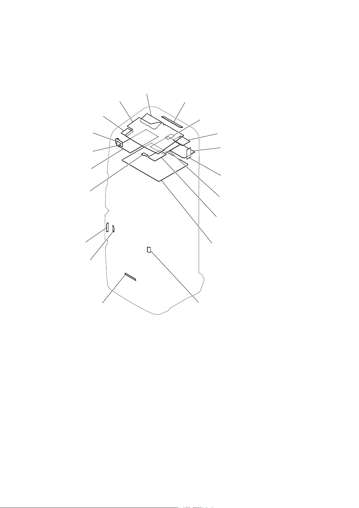
• Circuit Boards Location
POWER BUTTON board
SENSOR board
SECTION 6
DIAGRAMS
LCD board
SPK PARTY LED board
FM-TUNER board
IR board
RC-S730 (WW)
2CH DAMP board
MS-476 board
ANTENNA board
SPK LED board
PARTY LED board
DUMMY board
89G board
USB board
BENTEN-MOTHERBOARD board
MIC board
REGULATOR, SWITCHING
(SSN-161AD)
SPK LED board
30
 Loading...