

Sony MHC-RG55S, MHC-RG66, MHC-RG55 User Manual

Mini Hi-Fi
Component
System
Operating Instructions
4-239-875-12(2)
MHC-RG66
MHC-RG55S
MHC-RG55
© 2002 Sony Corporation
1
WARNING
To prevent fire or shock hazard, do not
expose the unit to rain or moisture.
To prevent fire, do not cover the ventilation of the
apparatus with news papers, table-cloths, curtains,
etc. And don’t place lighted candles on the apparatus.
To prevent fire or shock hazard, do not place objects
filled with liquids, such as vases, on the apparatus.
Do not install the appliance in a confined space,
such as a bookcase or built-in cabinet.
This appliance is classified as
a CLASS 1 LASER product.
This label is located on the
rear exterior.
Don’t throw away the battery with
general house waste, dispose of it
correctly as chemical waste.
Except for European models
ENERGY STAR
registered mark.
As an ENERGY STAR® Partner,
Sony Corporation has determined
that this product meets the ENERGY
®
STAR
efficiency.
®
is a U.S.
guidelines for energy
Table of Contents
List of Button Locations
and Reference Pages
Main unit ............................................... 4
Sub woofer ............................................ 5
Remote Control ..................................... 6
Getting Started
Hooking up the system .......................... 7
Inserting two R6 (size AA) batteries
into the remote .............................. 10
Setting the clock .................................. 11
CD
Loading a CD ...................................... 11
Playing a CD — Normal Play/
Shuffle Play/Repeat Play............... 12
Programing CD tracks
— Program Play ............................ 13
Tuner
Presetting radio stations....................... 14
Listening to the radio
— Preset Tuning/
Manual Tuning .............................. 16
Using the Radio Data System
(RDS)* .......................................... 17
GB
2

Tape
Optional Components
Loading a tape .....................................17
Playing a tape ...................................... 18
Recording to a tape
— CD Synchro Recording/
Recording Manually/
Program Edit ................................. 19
Timer-recording radio programs .........20
Sound Adjustment
Selecting the sound system.................. 21
Using the sub woofer........................... 21
Adjusting the sound............................. 22
Selecting the sound effect.................... 22
Adjusting the graphic equalizer and
storing............................................ 23
Selecting the surround effect ............... 23
Display
Turning off the display
— Power Saving Mode ................. 24
Using the CD display .......................... 24
Other Features
Hooking up optional components........ 29
Listening to audio from a connected
component ..................................... 30
Recording on a connected
component ..................................... 30
Troubleshooting
Problems and remedies........................ 31
Messages ............................................. 32
Additional Information
Precautions .......................................... 33
Specifications ...................................... 34
* European model only
Enhancing video game sound
— Game Sync ...............................25
Changing the spectrum analyzer
display ...........................................25
Mixing video game sound with other
sound source — Game Mixing ..... 25
Singing along....................................... 26
Falling asleep to music
— Sleep Timer .............................. 27
Waking up to music — Daily Timer ... 27
GB
3
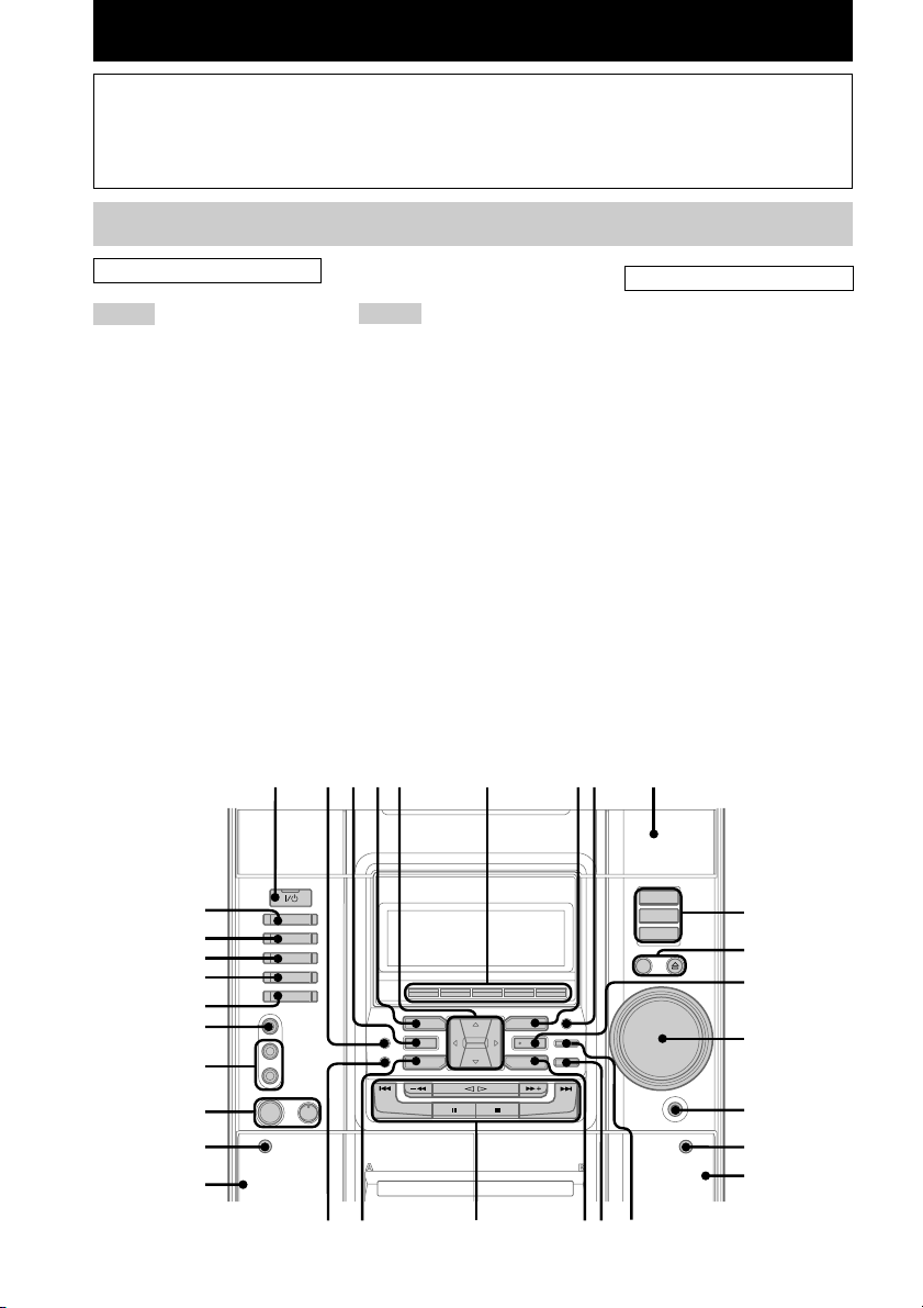
List of Button Locations and Reference Pages
How to use this page
Use this page to find the location of buttons and other
parts of the system that are mentioned in the text.
Main unit
ALPHABETICAL ORDER
A – G
AUDIO jacks wh (29)
CD es (12, 13, 19, 20)
CD SYNC qj (19, 20)
Deck A wd (1 7, 18)
Deck B qh (17 – 21, 26)
DIRECTION 6 (18 – 20, 26)
DISC 1 – 3 0 (12, 13, 20)
DISC SKIP/EX-CHANGE qa (11,
12)
Disc tray 9 (11)
DISPLAY 6 (17, 24)
EDIT 6 (20)
EFFECT ON/OFF 3 (22 )
ENTER qs (11, 13 – 15, 20, 23,
27, 28)
FM MODE 6 (16)
GAME wk (25)
GAME EQ wa (22)
GAME MIXING ws (25)
GROOVE 2 (22)
M – Z
MD (VIDEO) wl (30)
MIC jack*1 wg (26)
MIC LEVEL control*1 wg (26)
MOVIE EQ 7 (22)
MUSIC EQ 4 (22)
P FILE ql (23)
PHONES jack qf
PLAY MODE 6 (12, 13, 20)
REC PAUSE/START qk (19, 20,
26)
REPEAT 6 (12)
SPECTRUM 6 (25)
SURROUND SPEAKER
MODE*2 8 (21)
TAPE A/B e; (17, 19)
TUNER MEMORY 6 (14, 15)
TUNER/BAND ea (14 – 16, 19)
VIDEO jack wj (29)
VOLUME control qd
Illustration number
r
TUNER/BAND ea (14 – 16, 19)
Name of button/part Reference page
RR
BUTTON DESCRIPTIONS
?/1 (power) 1
v/V/b/B 5
Z OPEN/CLOSE qa
Z (deck B) qg
M w;
. w;
x w;
hH w;
X w;
> w;
m w;
Z (deck A) wf
1
*
Except for European models
*2MHC-RG66 only
12345 6 78 9
es
0
ea
e;
wl
qa
qs
wk
wj
qd
wh
wg
wf
wd
GB
4
w;waws
qjqkql
qf
qg
qh

Sub woofer
(MHC-RG55S only)
List of Button Locations and Reference Pages
ALPHABETICAL ORDER
A – Z
Indicator 1 (21)
ON/OFF 2 (21)
1
2
GB
5

Remote Control
ALPHABETICAL ORDER
A – G
CD qj (12, 13, 19, 20)
CLEAR 6 (13)
CLOCK/TIMER SELECT 2
(21, 28)
CLOCK/TIMER SET 3 (11, 20,
27)
D.SKIP ql (12)
EFFECT ON/OFF qa (22)
ENTER qf (11, 13 – 15, 20, 23,
27, 28)
GAME qk (25)
M – Z
MD (VIDEO) 9 (30)
P FILE qd (23)
PRESET +/– 5 (14 – 16)
PRESET EQ qg (22)
SLEEP 1 (27)
SURROUND 0 (23)
TAPE A/B 8 (17, 19)
TUNER/BAND qh (14 – 16, 19)
TUNING +/– 5 (14 – 16)
VOL +/– 7
12 34
ql
qk
qj
qh
qg
BUTTON DESCRIPTIONS
?/1 (power) 4
M 5
. 5
x 5
nN 5
X 5
> 5
m 5
v/V/b/B qs
5
6
7
8
9
0
qf
qd
qa
qs
GB
6
Getting Started
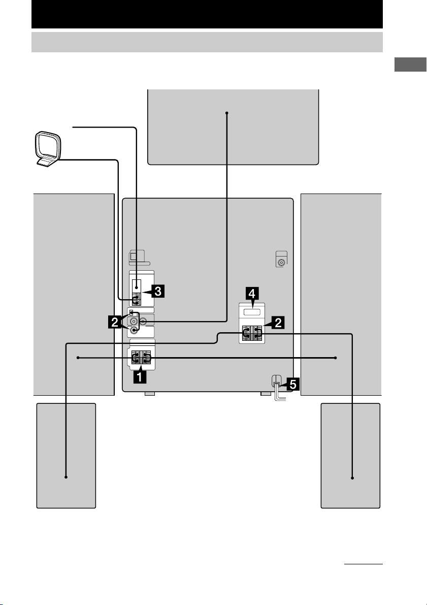
Hooking up the system
Perform the following procedure 1 to 5 to hook up your system using the supplied cords and
accessories.
FM antenna
AM loop antenna
Sub woofer speaker**
Front speaker (Right) Front speaker (Left)
Getting Started
Surround speaker (Right)* Surround speaker (Left)*
* MHC-RG66 only
** MHC-RG55S only
continued
GB
7
Hooking up the system (continued)
120V220V230 - 240V
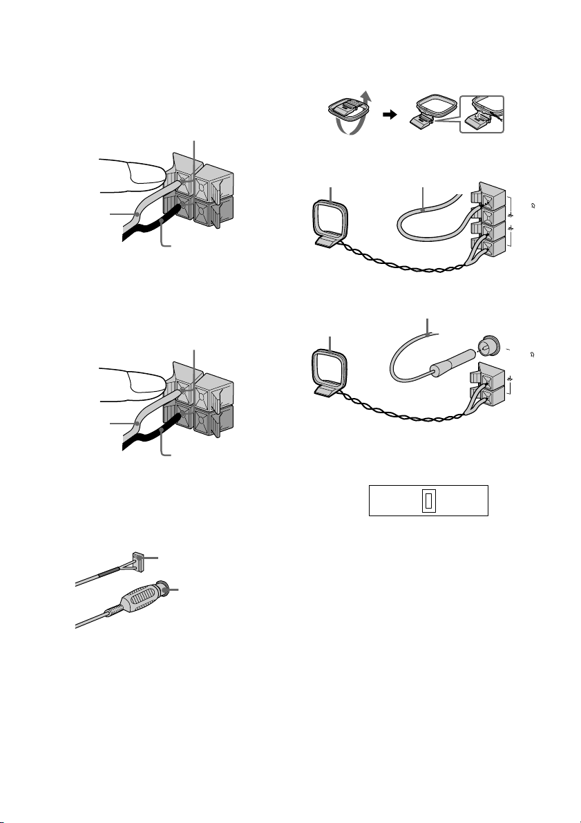
1 Connect the front speakers.
Connect the speaker cords to the SPEAKER
jacks as shown below.
Insert only the stripped portion
R
+
Red/Solid
(3)
Black/Stripe (#)
2 For MHC-RG66
Connect the surround speakers.
Connect the speaker cords to the
SURROUND SPEAKER jacks as shown
below.
Insert only the stripped portion
+
Red/Solid
(3)
Black/Stripe (#)
For MHC-RG55S
Connect the sub woofer speaker.
Connect the speaker cords to the SUB
WOOFER OUT jack and SUB WOOFER
CONTROL jack as shown below.
SUB WOOFER
CONTROL jack
L
R
L
SUB WOOFER
OUT jack
+
–
+
–
3 Connect the FM/AM antennas.
Set up the AM loop antenna, then connect
it.
Jack type A
AM loop antenna
Jack type B
AM loop antenna
Extend the FM lead antenna
horizontally
FM75
AM
Extend the FM lead
antenna horizontally
FM75
COAXIAL
AM
4 For models with a voltage selector, set
VOLTAGE SELECTOR to the local
power line voltage.
For MHC-RG55
Go to the procedure 3.
GB
8
5 Connect the power cord to a wall outlet.
The demonstration appears in the display.
When you press ?/1, the system turns on
and the demonstration automatically ends.
If the supplied adapter on the plug does not
fit your wall outlet, detach it from the plug
(only for models equipped with an adapter).
To connect optional components
See page 29.
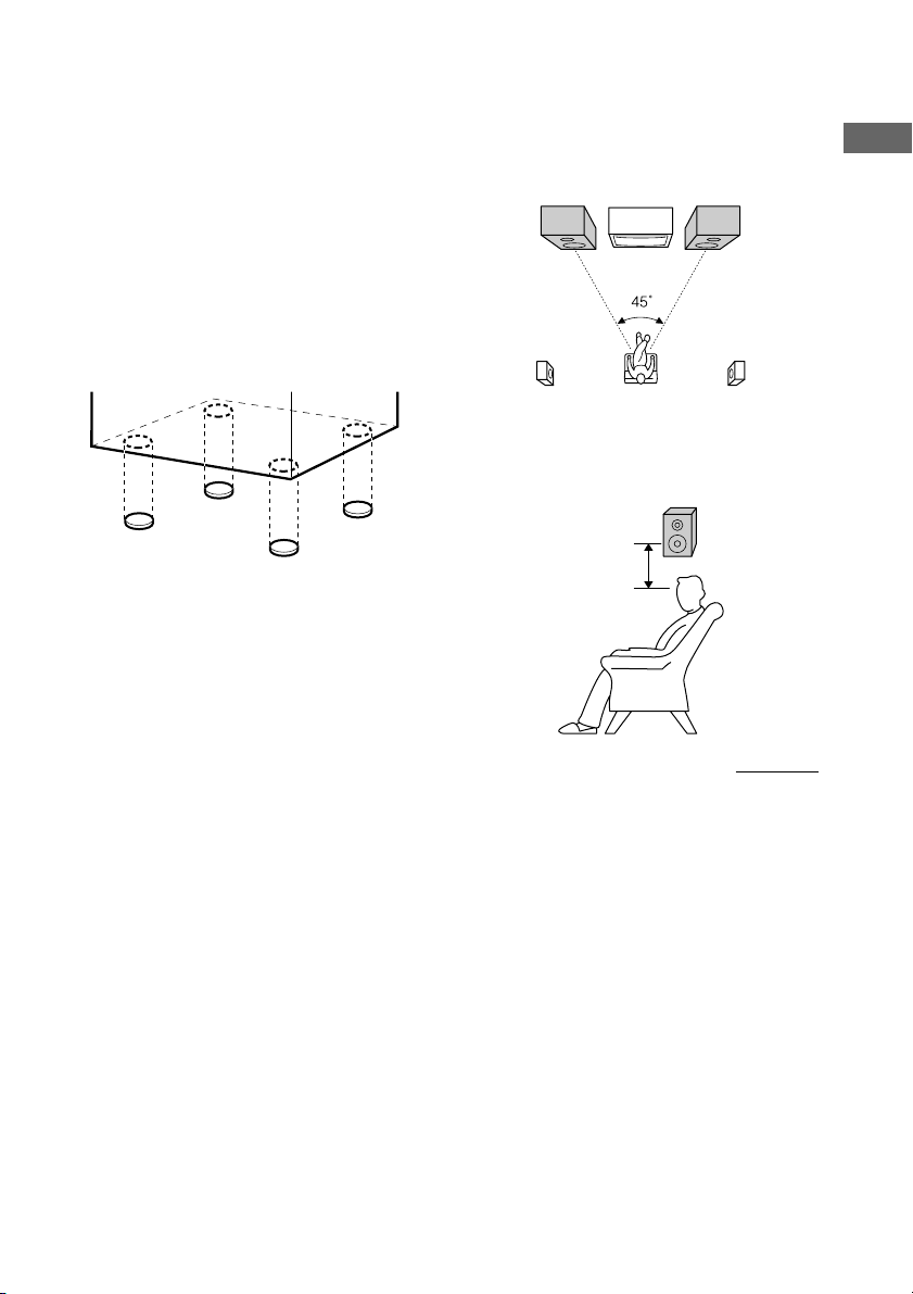
To attach the front speaker pads
Attach the supplied front speaker pads to the
bottom of the speakers to stabilize the speakers
and prevent them from slipping.
Notes
• Keep the speaker cords away from the antennas to
prevent noise.
• Do not place the surround speakers on top of a TV.
This may cause distortion of the colors in the TV
screen.
• Be sure to connect both left and right surround
speakers. Otherwise, the sound will not be heard.
Positioning the speakers (MHC-RG66
only)
1 Place the front speakers at an angle of
45 degrees from your listening
position.
Front
speaker
(L)
Surround
speaker
(L)
Front
speaker
(R)
Surround
speaker
(R)
2 Place the surround speakers facing
each other at about 60 to 90 cm above
your listening position.
Surround
speaker
60 to 90 cm
Getting Started
continued
GB
9
Hooking up the system (continued)
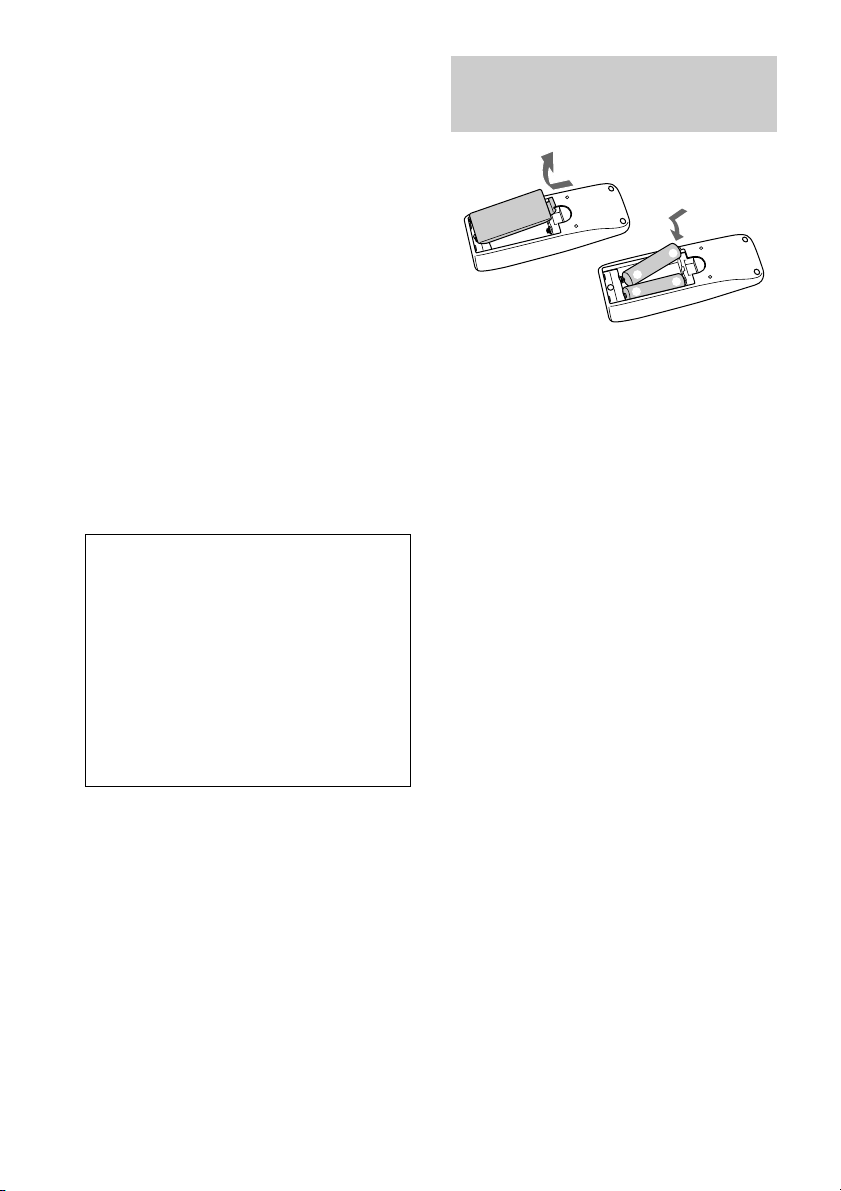
Inserting two R6 (size AA)
Positioning the sub woofer (MHCRG55S only)
Since the human ear cannot detect the direction
and position where the bass sound being
reproduced by a woofer (below 150 Hz) comes
from, you can place the woofer wherever you
like in your room. To obtain a better bass
reproduction, we recommend you to place the
woofer on a solid floor where the resonance is
unlikely to occur.
Notes
• Always place the woofer vertically, keeping a few
centimeters from away the wall.
• If the woofer is placed in the center of a room, the
bass could be extremely weakened. This is due to
the influence of the standing wave of the room. If
this happened, move the woofer away from the
center of a room or eliminate the cause of the
standing wave, by placing a bookshelf on the wall,
etc.
When carrying this system
Perform the following procedure to protect
the CD mechanism.
1 Make sure that all discs are removed
from the system.
2 Hold down CD and then press ?/1 until
“STANDBY” appears.
When you release the buttons, “LOCK”
appears.
3 Unplug the power cord.
batteries into the remote
e
E
E
e
Tip
With normal use, the batteries should last for about
six months. When the remote no longer operates the
system, replace both batteries with new ones.
Note
If you do not use the remote for a long period of time,
remove the batteries to avoid possible damage from
battery leakage.
10
GB

CD
Setting the clock
1 Press ?/1 to turn on the system.
2 Press CLOCK/TIMER SET on the
remote.
3 Press v or V repeatedly to set the hour.
4 Press B.
The minute indication flashes.
5 Press v or V repeatedly to set the
minute.
6 Press ENTER.
The clock starts working.
To adjust the clock
1 Press CLOCK/TIMER SET on the remote.
2 Press v or V repeatedly to select “CLOCK
SET”, then press ENTER.
3 Do the same procedures as step 3 to 6
above.
Note
The clock settings are canceled when you disconnect
the power cord or if a power failure occurs.
Loading a CD
1 Press Z OPEN/CLOSE.
The disc tray opens.
2 Place a CD with the label side up on the
disc tray.
To insert additional discs, press DISC
SKIP/EX-CHANGE to rotate the disc tray.
3 Press Z OPEN/CLOSE to close the disc
tray.
CD
11
GB
 Loading...