

Sony HCDSC-5, HCDSC-6, HCDSC-8 Service manual
HCD-SC5/SC6/SC8
SERVICE MANUAL
Ver 1.0 2003. 09
PHOTO: HCD-SC5
HCD-SC5/SC6/SC8 are the amplifier, DVD/
SACD and tuner section in DAV-SC5/SC6/SC8.
SPECIFICATIONS
Amplifier section
Stereo mode 90 W + 90 W (4 ohms at
Surround mode Front: 90 W + 90 W
*Depending on the sound field settings and the source,
there may be no sound output.
Inputs VIDEO 1/VIDEO 2/TV:
1 kHz, THD 10 %)
(HCD-SC5)
100 W + 100 W (4 ohms
at 1 kHz, THD 10 %)
(HCD-SC6/SC8)
(HCD-SC5)
100 W + 100 W
(HCD-SC6/SC8)
Centre*:
90 W
(HCD-SC5)
100 W
(HCD-SC6/SC8)
Surround*: 90 W + 90W
(4 ohms at 1 kHz, THD
10 %)
(HCD-SC5)
100 W + 100 W (4 ohms
at 1 kHz, THD 10 %)
(HCD-SC6/SC8)
Subwoofer*: 100W
(4 ohms at 100 Hz, THD
10 %)
(HCD-SC5/SC6)
Sensitivity: 150 mV
Impedance: 50 kilohms
(AEP, UK and Russian
models)
VIDEO 1:
Sensitivity: 150 mV
Impedance: 50 kilohms
VIDEO 2:
Sensitivity: 300 mV
Impedance: 50 kilohms
(Other models)
Outputs VIDEO 1 (AUDIO
OUT):
Voltage: 1 V
Impedance: 1 kilohm
Phones Accepts low-and high-
impedance headphones.
Super Audio CD/DVD system
Laser Semiconductor laser
(Super Audio CD/DVD: λ
= 650 nm)
(CD: λ = 780 nm)
Emission duration:
continuous
Signal format system NTSC or NTSC/PAL
Frequency response (at 2 CH STERE O mo de)
DVD (PCM): 2 Hz to 22
kHz (±1.0 dB)
CD: 2 Hz to 20 kHz (±1.
dB)
Harmonic distortion Less than 0.03 %
Tuner section
System PLL quartz-locked digital
synthesizer system
FM tuner section
Tuning range 87.5 – 108.0 MHz (50 kHz
step)
Aerial FM wire aerial
Aerial terminals 75 ohms, unbalanced
Intermediate frequency 10.7 MHz
AM tuner section
Tuning range
AEP, UK, Russian, Australian, Singapore and
Middle Easten models: 531 – 1,602 kHz (with the
interval set at 9 kHz)
AEP Model
UK Model
E Model
HCD-SC5/SC6/SC8
Australian Model
Model Name Using Similar Mechanism NEW
Mechanism T ype
Optical Pick-up Name
Other models: 531 – 1,602 kHz (with the
interval set at 9 kHz)
530 – 1,710 kHz (with the
interval set at 10 kHz)
Aerial AM loop aerial
Intermediate frequency 450 kHz
Vi
(AEP, UK and Russian models)
Inputs Video: 1 Vp-p 75 ohms
Outputs Video: 1 Vp-p 75 ohms
Video section (Other models)
Inputs Video: 1 Vp-p 75 ohms
Outputs Video: 1 Vp-p 75 ohms
0
General
Power requirements
European models: 230 V AC, 50/60 Hz
Australian and Asian models:
Taiwan models: 120 V AC, 50/60 Hz
Other models: 110 – 120 V AC, 50/60 Hz
Dimensions (approx.) 380 × 60 × 337 mm (w/h/d)
Mass (approx.) 4.2 kg
Operating temperature 5°C to 35°C (41°F to 95°F)
Operating humidity 5 % to 90 %
Design and specification are subject to change without
notice.
deo section (VIDEO 1, 2, EURO AV)
CDM80-DVBU24
TDP022W
S video:
Y: 1 Vp-p 75 ohms
C: 0.286 Vp-p 75 ohms
COMPONENT:
Y: 1 Vp-p 75 ohms
P
B/CB, PR/CR: 0.7 Vp-p
75 ohms
220 – 240 V AC, 50/60 Hz
incl. projecting parts
HCD-SC6/SC8
9-961-137-01
2003I1678-1
© 2003.09
SACD/DVD RECEIVER
Sony Corporation
Home Audio Company
Published by Sony Engineering Corporation

HCD-SC5/SC6/SC8
Laser component in this product is capable of emitting radiation
exceeding the limit for Class 1.
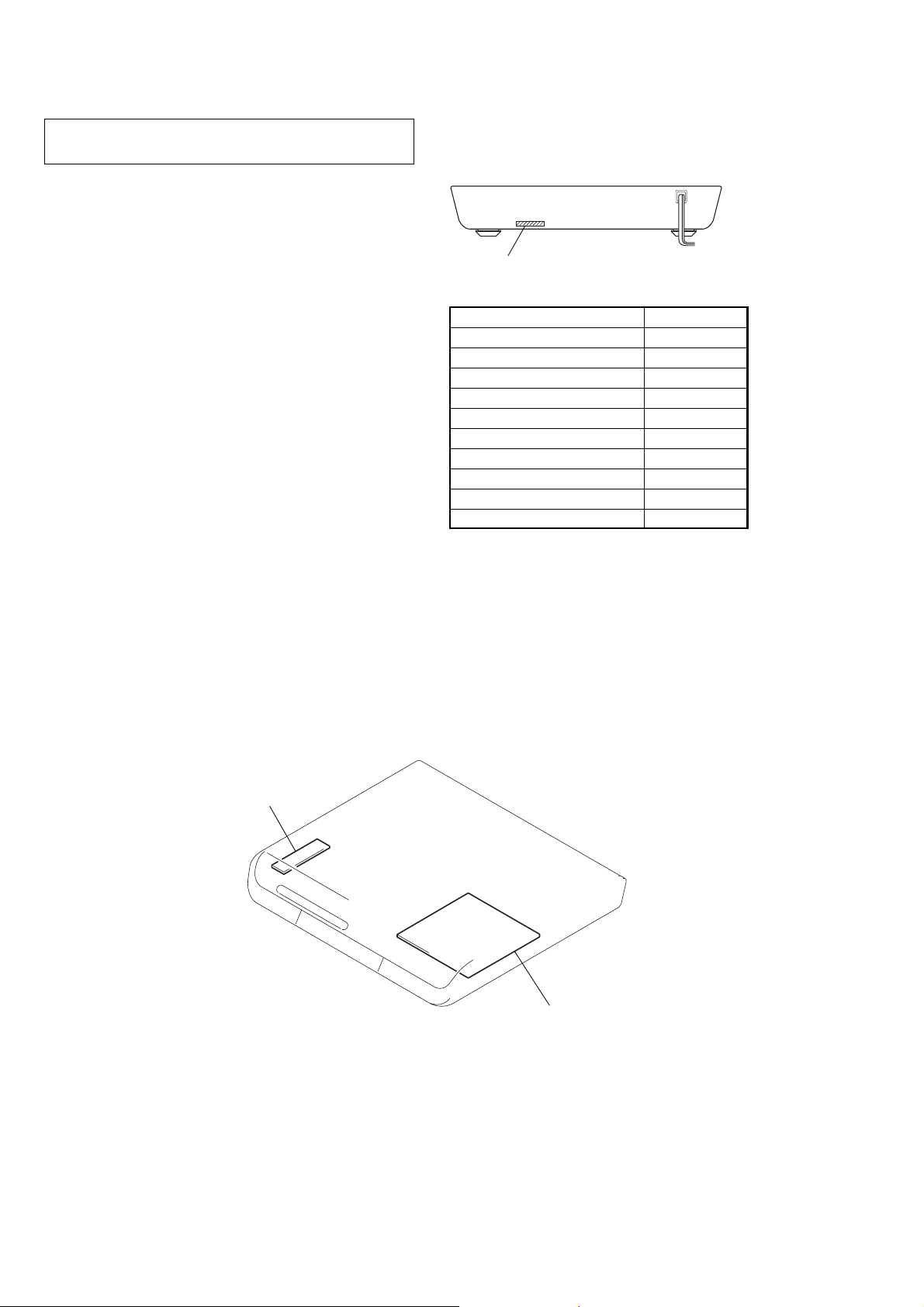
This appliance is classified as
a CLASS 1 LASER product.
The CLASS 1 LASER
PRODUCT MARKING is
located on the rear exterior.
CAUTION
Use of controls or adjustments or performance of procedures
other than those specified herein may result in hazardous
radiation exposure.
Notes on chip component replacement
•Never reuse a disconnected chip component.
• Notice that the minus side of a tantalum capacitor may be
damaged by heat.
Flexible Circuit Board Repairing
•Keep the temperature of soldering iron around 270˚C
during repairing.
• Do not touch the soldering iron on the same conductor of the
circuit board (within 3 times).
• Be careful not to apply force on the conductor when soldering
or unsoldering.
Unleaded solder
Boards requiring use of unleaded solder are printed with the leadfree mark (LF) indicating the solder contains no lead.
(Caution: Some printed circuit boards may not come printed with
the lead free mark due to their particular size.)
: LEAD FREE MARK
Unleaded solder has the following characteristics.
• Unleaded solder melts at a temperature about 40°C higher than
ordinary solder.
Ordinary soldering irons can be used but the iron tip has to be
applied to the solder joint for a slightly longer time.
Soldering irons using a temperature regulator should be set to
about 350°C.
Caution: The printed pattern (copper foil) may peel away if the
heated tip is applied for too long, so be careful!
• Strong viscosity
Unleaded solder is more viscous (sticky, less prone to flow) than
ordinary solder so use caution not to let solder bridges occur such
as on IC pins, etc.
• Usable with ordinary solder
It is best to use only unleaded solder but unleaded solder may
also be added to ordinary solder.
SAFETY-RELATED COMPONENT WARNING!!
COMPONENTS IDENTIFIED BY MARK 0 OR DOTTED LINE WITH
MARK 0 ON THE SCHEMATIC DIAGRAMS AND IN THE PARTS
LIST ARE CRITICAL TO SAFE OPERATION. REPLACE THESE
COMPONENTS WITH SONY PARTS WHOSE PART NUMBERS
APPEAR AS SHOWN IN THIS MANUAL OR IN SUPPLEMENTS
PUBLISHED BY SONY.
2

TABLE OF CONTENTS
HCD-SC5/SC6/SC8
1. SERVICING NOTE ·························································· 4
2. GENERAL ·········································································· 5
3. DISASSEMBLY ································································ 9
3-1. FRONT PANEL SECTION,
SIDE PANEL (L/R) SECTION ···································10
3-2. DDCON BOARD, FL BOARD ··································· 11
3-3. PLAY BUTTON, SLOT DISC ····································11
3-4. POWER BOARD·························································12
3-5. I/O BOARD ·································································12
3-6. SCART BOARD, DVD BOARD ·································13
3-7. AMP BOARD ······························································ 13
3-8. CD MECHANISM DECK (CDM80-DVBU24) ········· 14
3-9. CHASSIS (TOP) ·························································· 14
3-10. LEVER (LOADING R/L)··········································15
3-11. DISC STOP LEVER, DISC SENSOR LEVER········· 16
3-12. DRIVER BOARD ······················································16
3-13. RF BOARD ································································17
3-14. OPTICAL PICK-UP (TDP022W) ·····························17
3-15. BASE UNIT ······························································· 18
3-16. LEVER (BU LOCK)··················································18
3-17. CLOSE LEVER ························································· 19
3-18. DIR LEVER, GEAR (IDL-B)····································19
3-19. GEAR (IDL-C) ·························································· 20
4. TEST MODE···································································· 21
5. ELECTRICAL ADJUSTMENT ·································· 29
6. DIAGRAMS
6-1. CIRCUIT BOARDS LOCATION ······························· 30
6-2. BLOCK DIAGRAMS – RF/SERVO SECTION –······ 32
– AUDIO (DSP) SECTION – ······································ 33
– AUDIO OUT SECTION – ······································· 34
– VIDEO SECTION –················································· 35
– POWER SUPPLY SECTION – ································ 36
6-3. PRINTED WIRING BOARD – RF SECTION –········ 37
6-4. SCHEMATIC DIAGRAM – RF SECTION –············· 38
6-5. PRINTED WIRING BOARD
– DRIVER SECTION – ·············································· 39
6-6. SCHEMATIC DIAGRAM
– DRIVER SECTION – ·············································· 39
6-7. PRINTED WIRING BOARD
– DVD SECTION (SIDE A) – ···································· 40
6-8. PRINTED WIRING BOARD
– DVD SECTION (SIDE B) – ····································41
6-9. SCHEMATIC DIAGRAM
– DVD SECTION (1/10) –·········································· 42
6-10.SCHEMATIC DIAGRAM
– DVD SECTION (2/10) –·········································· 43
6-11.SCHEMATIC DIAGRAM
– DVD SECTION (3/10) –·········································· 44
6-12.SCHEMATIC DIAGRAM
– DVD SECTION (4/10) –·········································· 45
6-13.SCHEMATIC DIAGRAM
– DVD SECTION (5/10) –·········································· 46
6-14.SCHEMATIC DIAGRAM
– DVD SECTION (6/10) –·········································· 47
6-15.SCHEMATIC DIAGRAM
– DVD SECTION (7/10) –·········································· 48
6-16.SCHEMATIC DIAGRAM
– DVD SECTION (8/10) –·········································· 49
6-17.SCHEMATIC DIAGRAM
– DVD SECTION (9/10) –·········································· 50
6-18.SCHEMATIC DIAGRAM
– DVD SECTION (10/10) –········································ 51
6-19.PRINTED WIRING BOARD
– AMP SECTION (SIDE A) – ···································· 52
6-20.PRINTED WIRING BOARD
– AMP SECTION (SIDE B) – ···································· 53
6-21.SCHEMATIC DIAGRAM
– AMP SECTION (1/2) –············································ 54
6-22.SCHEMATIC DIAGRAM
– AMP SECTION (2/2) –············································ 55
6-23.PRINTED WIRING BOARD
– I/O SECTION –························································56
6-24.SCHEMATIC DIAGRAM
– I/O SECTION (1/2) – ··············································· 57
6-25.SCHEMATIC DIAGRAM
– I/O SECTION (2/2) – ··············································· 58
6-26.PRINTED WIRING BOARD
– FRONT PANEL SECTION –···································59
6-27.SCHEMATIC DIAGRAM
– FRONT PANEL SECTION –···································60
6-28.PRINTED WIRING BOARD
– POWER SECTION – ··············································· 61
6-29.SCHEMATIC DIAGRAM
– POWER SECTION – ··············································· 62
6-30.IC BLOCK DIAGRAMS ············································65
6-31.IC PIN FUNCTION DESCRIPTION ························· 73
7. EXPLODED VIEWS
7-1. CASE SECTION·························································94
7-2. FRONT PANEL SECTION········································· 95
7-3. CHASSIS SECTION-1 ··············································· 96
7-4. CHASSIS SECTION-2 ··············································· 97
7-5. CHASSIS SECTION-3 ··············································· 98
7-6. MECHANISM DECK SECTION-1
(CDM80-DVBU24)····················································· 99
7-7. MECHANISM DECK SECTION-2
(CDM80-DVBU24)··················································· 100
7-8. MECHANISM DECK SECTION-3
(CDM80-DVBU24)··················································· 101
7-9. BASE UNIT SECTION ············································ 102
8. ELECTRICAL PARTS LIST ····································· 103
3
HCD-SC5/SC6/SC8
SECTION 1
SERVICING NOTE
NOTES ON HANDLING THE OPTICAL PICK-UP BLOCK
OR BASE UNIT
The laser diode in the optical pick-up block may suffer electrostatic
break-down because of the potential difference generated by the
charged electrostatic load, etc. on clothing and the human body.
During repair, pay attention to electrostatic break-down and also
use the procedure in the printed matter which is included in the
repair parts.
The flexible board is easily damaged and should be handled with
care.
NOTES ON LASER DIODE EMISSION CHECK
The laser beam on this model is concentrated so as to be focused on
the disc reflective surface by the objective lens in the optical pickup block. Therefore, when checking the laser diode emission,
observe from more than 30 cm away from the objective lens.
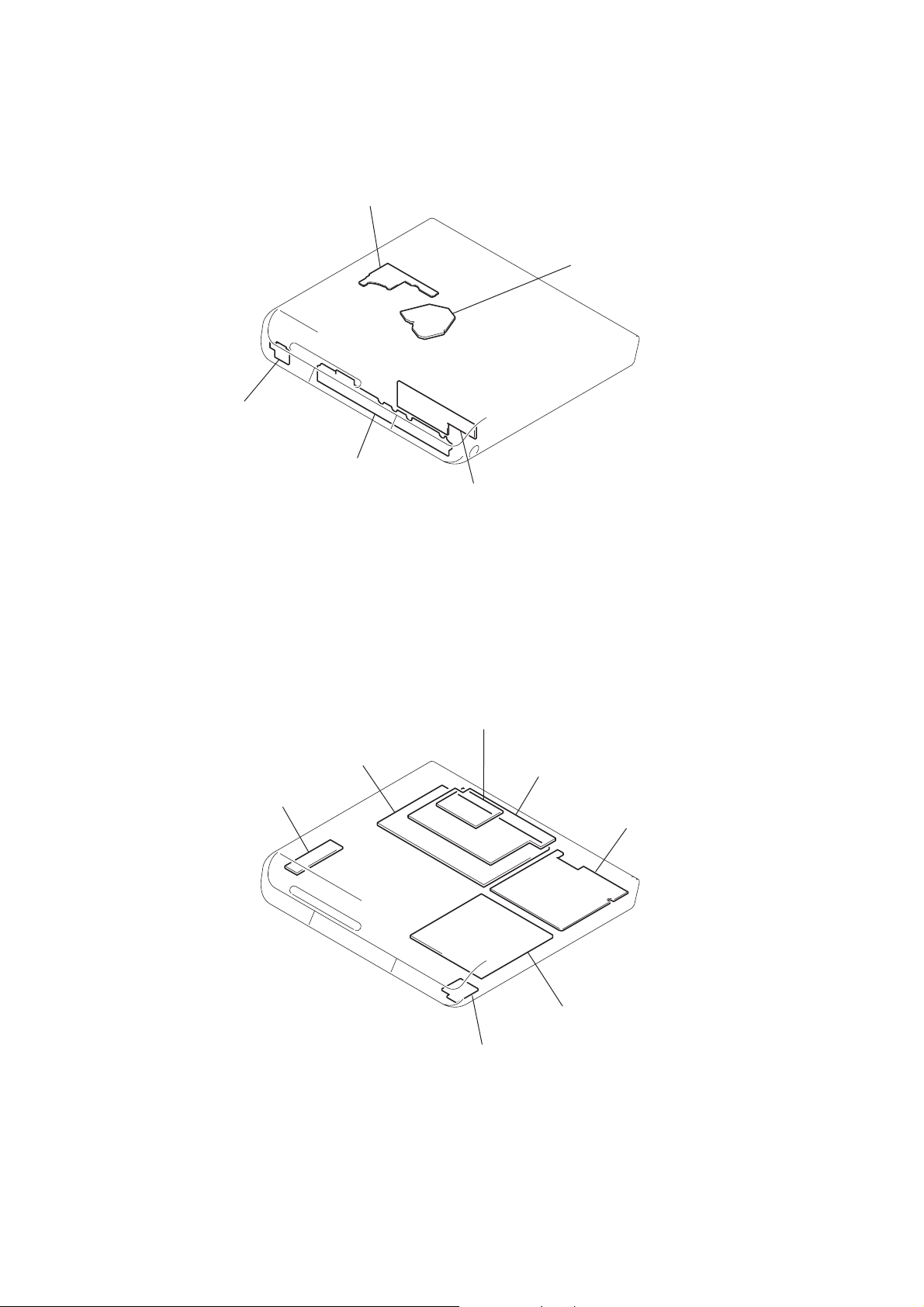
MODEL IDENTIFICATION
— BACK PANEL —
Part No.
Model
SC5:AEP,UK/SC6:AEP,UK
SC5:EA/SC6:EA
SC5:SP,HK,KR,TW/SC6:SP,KR
SC5:E32/SC6:AUS
SC8:AEP,UK
SC8:EA
SC8:SP,HK,KR,TW
SC8:E32,MX,AUS
SC5:RU/SC6:RU
SC8:RU
•Abbreviation
AUS: Australian model
E32 : 110-240V AC area in E model
EA : Saudi Arabia model
HK : Hong Kong model
KR : Korean model
MX : Mexican model
RU : Russian model
SP : Singapore model
TW : Taiwan model
PARTS No.
4-248-563-0s
4-248-563-1s
4-248-563-2s
4-248-563-3s
4-248-563-5s
4-248-563-6s
4-248-563-7s
4-248-563-8s
4-250-335-1s
4-250-335-2s
LF board
POWER board
AEP and UK models of HCD-SC6 and HCD-SC8 should exchange
for POWER SWITCHING (1-468-790-11) .
These do not correspond with DIAGRAMS and ELECTRICAL PARTS LIST .
4
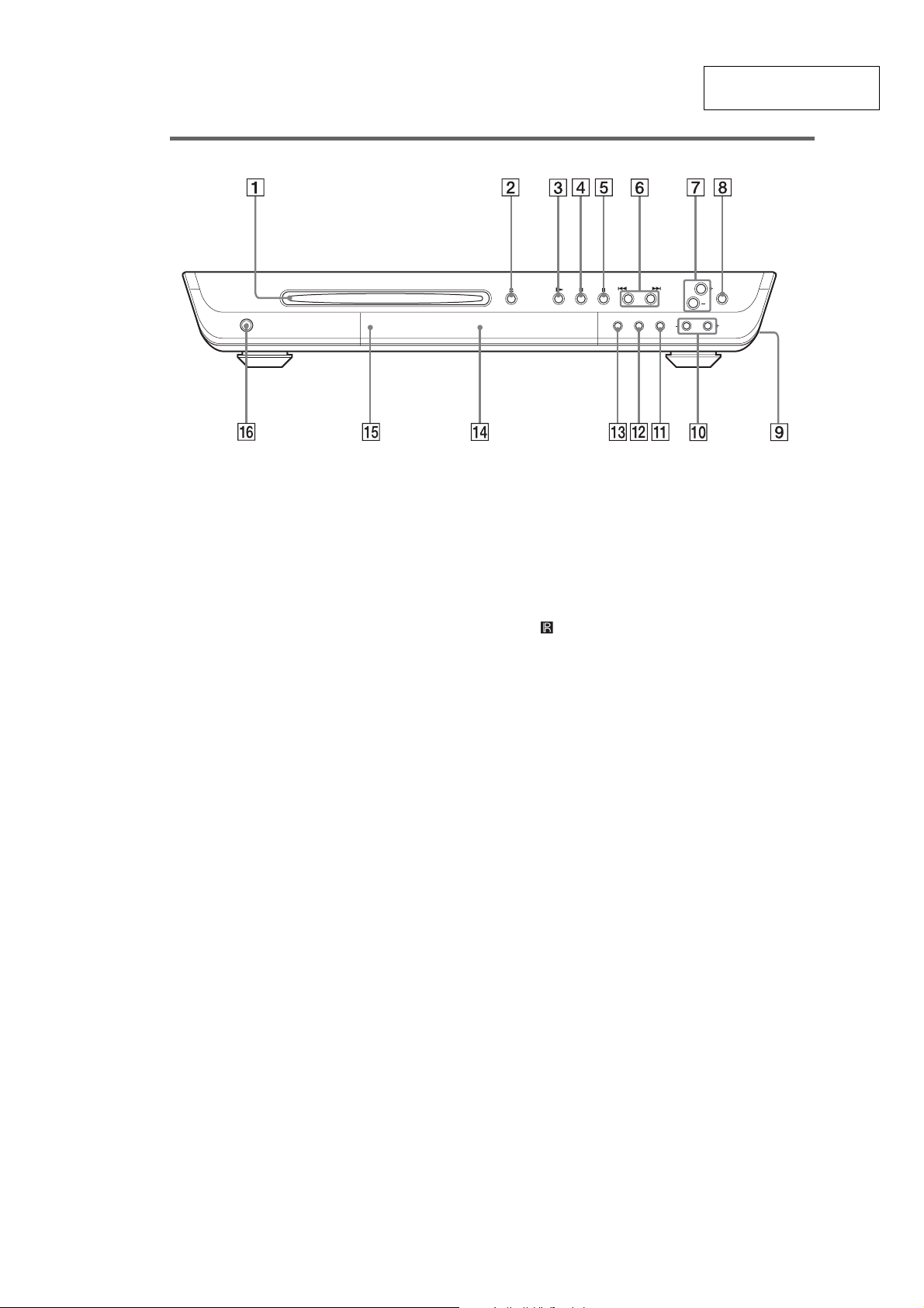
Front Panel
SECTION 2
GENERAL
HCD-SC5/SC6/SC8
This section is extracted
from instruction manual.
A Disc slot (22)
B A (eject) (22)
C H (play) (22)
D X (pause) (23)
E x (stop) (23)
F ./>, PREV/ N EXT, PRESET –/+
(23, 25, 56, 57)
G VOLUME +/– (22, 67)
H BASS LEVEL (46)
I PHONES (on the side of the system)
jack (22)
J SOUND FIELD –/+ (43, 44, 45)
K DISPLAY (36, 39, 57)
L BAND (56, 57)
M FUNCTION (22, 55, 57)
N Front panel display (77)
O (remo te sensor) (11)
P [/1 (power) switch/S TANDBY indicator
(22)
5
HCD-SC5/SC6/SC8
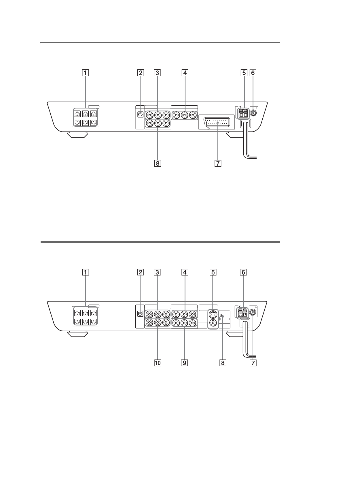
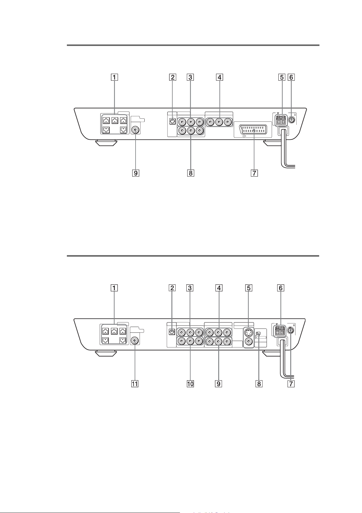
Rear Pan
el
HCD-SC5/SC6 (AEP, UK and Russian models)
CENTER FRONT LFRONT R
WOOFER SURR LSURR R
SPEAKER
VIDEO 2
VIDEO 1
RL
OPTICAL
DIGITAL
RL
IN
A SPEAKER jacks (13)
B VIDEO 2 OPTICAL DIGITAL IN jack (19)
C VIDEO 1 ANALOG OUT jack (18)
D VIDEO 2 ANALOG IN jack (18)
VIDEO OUTAUDIO OUT
VIDEO 2
RL
VIDEO INAUDIO IN
VIDEO INAUDIO IN
E AM terminals (16)
F FM 75 COAXIAL jack (16)
G EURO AV OUTPUT (TO TV) jacks (18)
H VIDEO 1 ANALOG IN jack (18)
EURO AV
OUTPUT(TO TV)
AM
FM 75
COAXIAL
Re
ar Panel
HCD-SC5/SC6 (Other models)
SPEAKER
CENTER FRONT LFRONT R
WOOFER SURR LSURR R
A SPEAKER jacks (13)
B VIDEO 2 OPTICAL DIGITAL IN jack (18)
C VIDEO 1 ANAL OG OUT jack (18)
D VIDEO 2 ANAL OG IN ja c k (18)
E MONITOR O UT (VIDEO/S VIDEO) jacks
(18)
VIDEO 2
VIDEO 1
RL
OPTICAL
DIGITAL
RL
IN
VIDEO OUTAUDIO OUT
VIDEO INAUDIO IN
VIDEO 2
RL
YPB/CB PR/CR
VIDEO INAUDIO IN
MONITOR OUT
S VIDEO (DVD ONLY)
COMPONENT
VIDEO OUT
VIDEO
SCAN SELECT
SELECTABLE
INTERLACE
COMPONENT
VIDEO OUT
AM
FM 75
COAXIAL
F AM terminals (16)
G FM 75 COAXIAL jack (16)
H SCAN SELECT switch (64)
I COMPONENT VIDEO OUT jacks (18)
J VIDEO 1 ANALOG IN jack (18)
6
Re
ar Panel
HCD-SC8 (AEP, UK and Russian models)
HCD-SC5/SC6/SC8
CENTER FRONT LFRONT R
SPEAKER
SURR LSURR R
SUB
WOOFER
AUDIO
OUT
VIDEO 2
VIDEO 1
RL
OPTICAL
DIGITAL
RL
IN
A SPEAKER jacks (13)
B VIDEO 2 OPTICAL DIGITAL IN jack (19)
C VIDEO 1 ANAL OG OUT jack (18)
D VIDEO 2 ANAL OG IN ja c k (18)
E AM terminals (16)
R
ear Panel
HCD-SC8 (Other models)
VIDEO OUTAUDIO OUT
VIDEO INAUDIO IN
VIDEO 2
RL
VIDEO INAUDIO IN
EURO AV
OUTPUT(TO TV)
AM
FM 75
COAXIAL
F FM 75 COAXIAL jack (16)
G EURO AV OUTPUT (TO TV) jacks (18)
H VIDEO 1 ANALOG IN jack (18)
I SUB WOOFER AUDIO OUT jack (12)
CENTER FRONT LFRONT R
SPEAKER
SURR LSURR R
SUB
WOOFER
AUDIO
OUT
VIDEO 2
VIDEO 1
RL
OPTICAL
DIGITAL
RL
IN
A SPEAKER jacks (13)
B VIDEO 2 OPTICAL DIGITAL IN jack (18)
C VIDEO 1 ANALOG OUT jack (18)
D VIDEO 2 ANALOG IN jack (18)
E MONITOR OUT (VIDEO/S VIDEO) jacks
(18)
VIDEO OUTAUDIO OUT
VIDEO INAUDIO IN
VIDEO 2
RL
YPB/CBPR/C
VIDEO INAUDIO IN
R
MONITOR OUT
S VIDEO (DVD ONLY)
COMPONENT
VIDEO OUT
VIDEO
SCAN SELECT
SELECTABLE
INTERLACE
COMPONENT
VIDEO OUT
AM
FM 75
COAXIAL
F AM terminals (16)
G FM 75 COAXIAL jack (16)
H SCAN SELECT switch (65)
I COMPONENT VIDEO OUT jacks (18)
J VIDEO 1 ANALOG IN jack (18)
K SUB WOOFER AUDIO OUT jack (12)
7
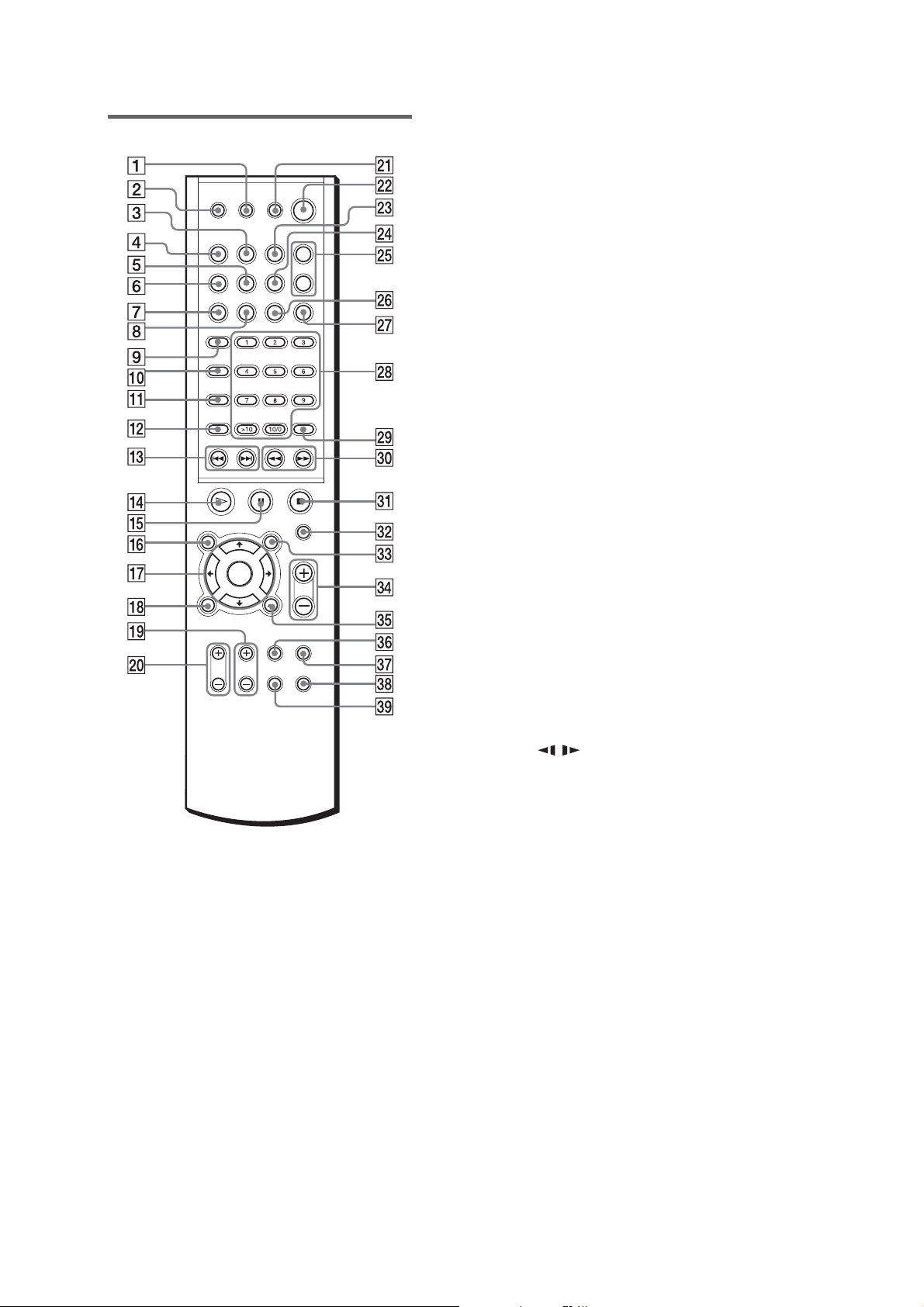
HCD-SC5/SC6/SC8
Remote
Note
This remote control glows in the dark. Ho wev er,
before glowing, the remote must be exposed to light for
awhile.
A SLEEP (59)
B
Z
(eject) (22, 23)
C DISPLAY (36, 39, 57)
D FUNCTION (22, 55, 57)
E STEREO/MONO (57)
F BAND (56, 57)
G PLAY MODE (30, 31)
H CLEAR (30, 31, 32, 34)
I TV (54)
J AUDIO (41)
K ANGLE (47)
L SUBTITLE (48)
M ./>, PREV/NEXT, PRESET –/+ (23,
25, 56, 57)
N H (play) (22, 25, 30, 31, 32)
O X (pause) (23)
P DVD TOP MENU/ALBUM– (24, 26, 28)
Q C/X/x/c/ENTER (24, 25, 26, 28, 29, 30,
32, 34, 41, 47, 48, 49, 51, 58, 60, 61)
R DVD DISPLAY (26, 28, 32, 34, 39, 40, 41,
47, 48, 49)
S TV CH +/– (54)
T TV VOL +/– (54)
U TV [/1 (on/standby) (54)
V "/1 (standby) (22, 56)
W REPEAT (30, 32)
X NAME (58)
Y SOUND FIELD +/– (43, 44, 45)
Z MEMORY (56)
wj NIGHT MODE (46)
wk Number buttons (24, 25, 30, 34, 47, 49,
51, 54)
wl ENTER (56)
e; m/M// SLOW, TUNING –/+ (29,
33, 56)
ez x (stop) (23, 24, 25, 49)
es MUTING (23)
ed DVD MENU/ALBUM+ (24, 26, 28)
ef VOLUME +/– (57)
eg O RETURN (25, 26, 28, 30, 34, 49, 51,
61)
eh TV/VIDEO (54)
ej BASS LEVEL (46)
ek AMP MENU (60)
el DVD SETUP (51, 61)
8
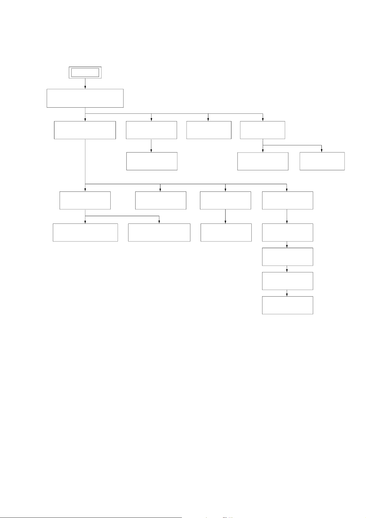
SECTION 3
DISASSEMBLY
• The equipment can be removed using the following procedure.
SET
FRONT PANEL SECTION,
SIDE PANEL (L / R) SECTION
HCD-SC5/SC6/SC8
CD MECHANISM DECK
(CDM80-DVBU24)
CHASSIS (TOP)
LEVER (LOADING R / L)
DDCON BOARD,
FL BOARD
PLAY BUTTON,
SLOT DISC
DRIVER BOARD RF BOARD
DISC STOP LEVER,
DISC SENSOR LEVER
POWER BOARD I/O BOARD
OPTICAL PICK-UP
(TDP022W)
SCART BOARD,
DVD BOARD
BASE UNIT
LEVER (BU LOCK)
CLOSE LEVER
DIR LEVER,
GEAR (IDL-B)
AMP BOARD
GEAR (IDL-C)
9
HCD-SC5/SC6/SC8
)
Note: Follow the disassembly procedure in the numerical order given.
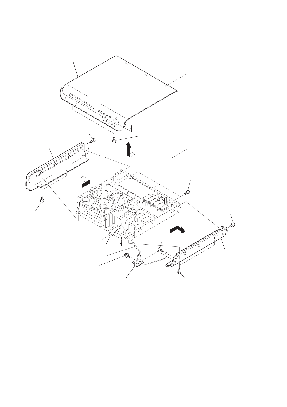
3-1. FRONT PANEL SECTION, SIDE PANEL (L/R) SECTION
5
front panel section
8
7
two screws
(+BVTP 3
side panel (L)
×
8)
6
two screws
(+BVTP 3
4
×
8)
wire (flat type)(CN814)
9
connector (CN900)
a
2
four screws
(+BVTP 3
3
a
×
8)
0
screw
(+BTP 3
×
6)
1
three screws
(+BVTP 3
×
8)
qd
two screws
(+BVTP 3
qg
side panel (R
×
8)
10
qa
screw
(+PTPWHM 2.6
×
6)
qs
HP board
qf
two screws
(+BVTP 3
×
8)
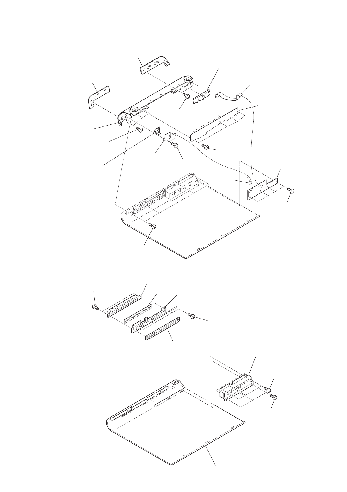
3-2. DDCON BOARD, FL BOARD
)
qg
panel top (R)
qs
panel top (L)
qh
front (ml) panel
qa
three screws
(DIA. 2.6
8
power button sub assy
×
8)
7
POWER LED board
qf
four screws
(DIA. 2.6
6
two screws
(DIA. 2.6
×
8)
×
qd
band button
9
(DIA. 2.6
8)
3
connector
(CN819)
four screws
×
8)
HCD-SC5/SC6/SC8
2
wire (flat type) (CN815)
q;
FL board
4
DDCON board
3-3. PLAY BUTTON, SLOT DISC
5
two screws
(+BVTP 3
×
8)
5
four screws
(DIA. 2.6
6
slot disc
×
7
8)
sheet
9
slot disc (inside)
8
cover slot
4
three screws
(+BVTP 3
×
8)
3
play button
1
(DIA. 2.6
2
three screws
(+BVTP 3
four screws
×
8)
×
8
q;
front (al) panel
1
three screws
(+BVTP 3
×
8)
11
HCD-SC5/SC6/SC8
)
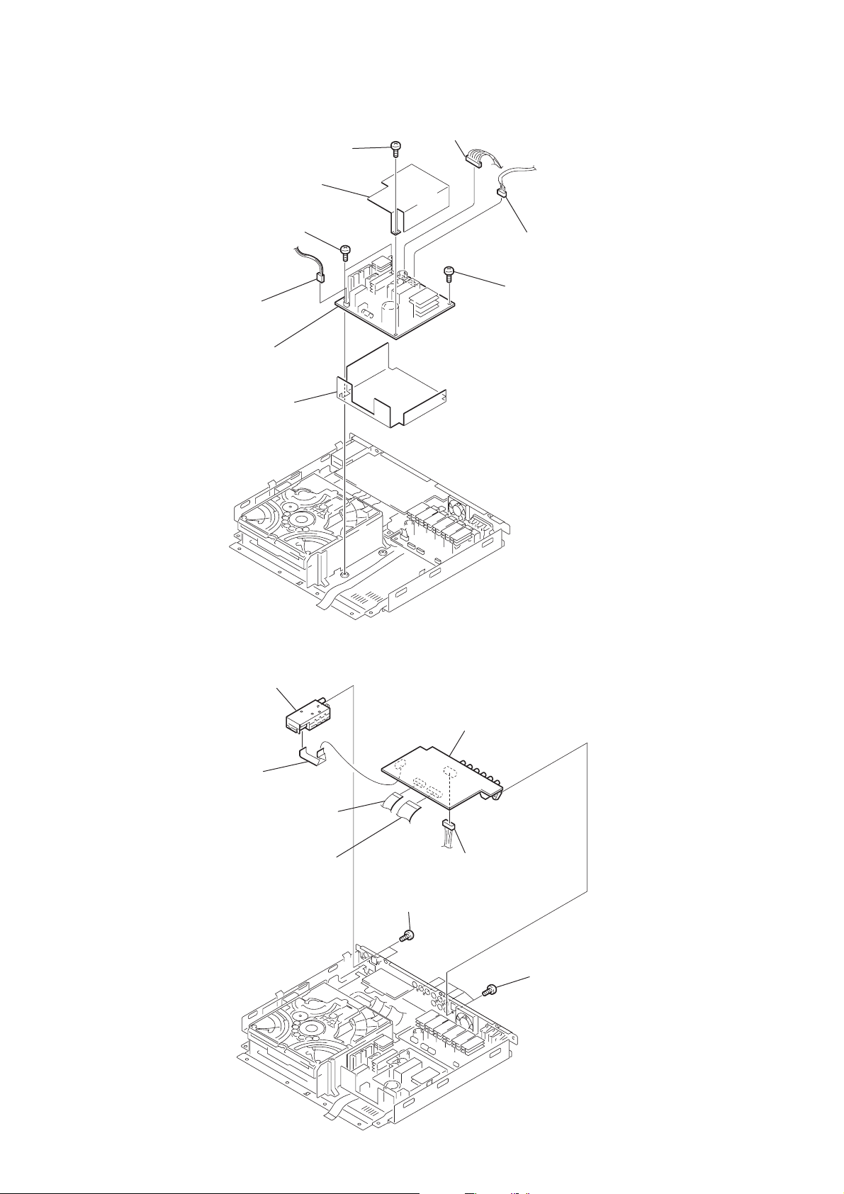
3-4. POWER BOARD
3
connector (CN902)
4
screw
(+BV SUMITITE B3)
5
power sheet
6
two screws
(+BV SUMITITE B3)
9
POWER board
8
power sheet
1
connector (CN903)
2
connector (CN904)
7
screw
(+BV SUMITITE B3)
3-5. I/O BOARD
5
wire (flat type)
8
tuner unit
2
wire (flat type)
(CN203)
3
wire (flat type)
(CN202)
7
two screws
(+BVTP 3
6
I/O board
4
connector (CN205)
(used only for AEP,UK and
Russian models)
×
8)
1
five screws
(+BVTP 3
×
8
12
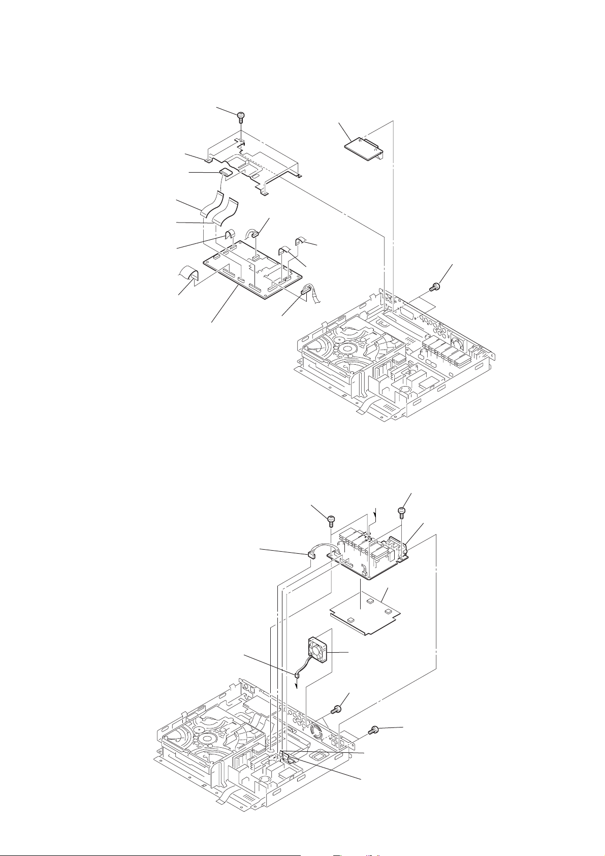
3-6. SCART BOARD, DVD BOARD
d
)
3
four screws
(+BV SUMITITE B3)
5
heat sink DVD
4
ferrite core
8
wire (flat type)
(CN003)
9
wire (flat type)
(CN002)
6
wire (flat type)
(CN005)
7
wire (flat type)
(CN401)
qf
DVD board
qd
connector
(CN007)
q;
connector
(CN008)
2
SCART board
(used only for AEP,UK and
Russian models)
qs
wire (flat type)
(CN001)
qa
wire (flat type)
(CN004)
HCD-SC5/SC6/SC8
1
two screws (+BVTP 3 × 8)
(used only for AEP,UK an
Russian models)
3-7. AMP BOARD
5
connector
(CN904)
2
connector
(CN302)
8
two screws
(+BV SUMITITE B3)
a
a
q;
3
DC fan
1
two screws
(+BVTT 4 × 8)
6
wire (flat type)
(CN304)
9
two screws
(+BV SUMITITE B3
qa
AMP board
amp sheet
4
two screws
(+BVTP 3 × 8)
7
wire (flat type)
(CN303)
13
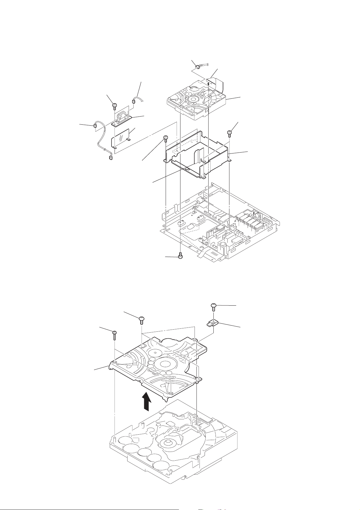
HCD-SC5/SC6/SC8
)
3-8. CD MECHANISM DECK (CDM80-DVBU24)
5
connector (CN900)
7
two screws
(+BVTP 3 × 8)
6
connector
(CN901)
q;
(+BV SUMITITE B3)
qs
MD cover sheet
9
sheet
two screws
8
LF board
3
connector (CN701)
2
wire (flat type) (CN401)
4
mechanism deck
(CDM80-DVBU24)
qa
two screws
(+BV SUMITITE B3)
qd
MD cover
3-9. CHASSIS (TOP)
3
5
chassis (top)
4
three screws
(+BVTP 2.6
two screws
(+P 2
×
10)
1
(+BVTP 3 × 8)
×
8)
three screws
1
screw
(+BVTP 2.6
2
lever (CL UP2
×
8)
14
)
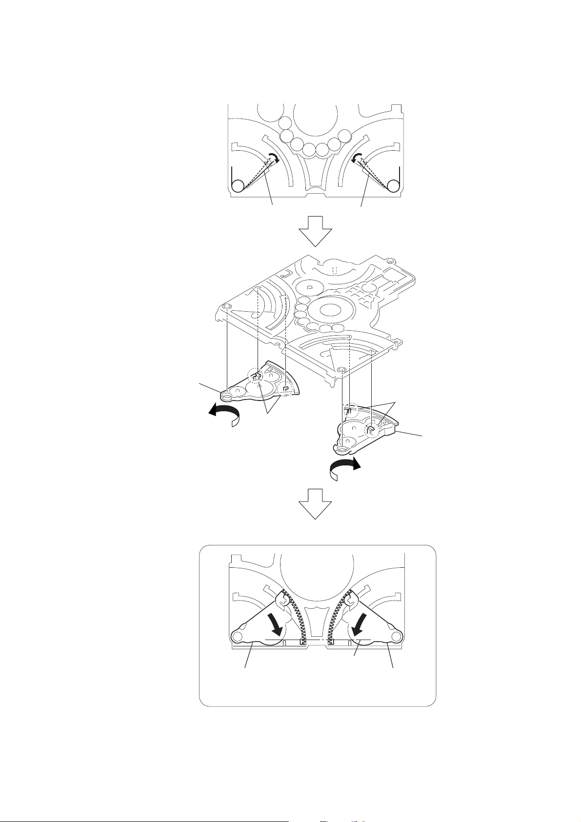
3-10. LEVER (LOADING R/L)
HCD-SC5/SC6/SC8
5
lever (loading R)
1
spr-T (loading L) spr-T (loading R)
4
two hooks
1
2
two hooks
3
lever (loading L
PRECAUTION DURING LEVER (LOADING R / L) INSTALLATION
Align the horizontal position.
lever (loading L)
Install the
both levers so that they move symmetrically.
lever (loading R)
15
HCD-SC5/SC6/SC8
)
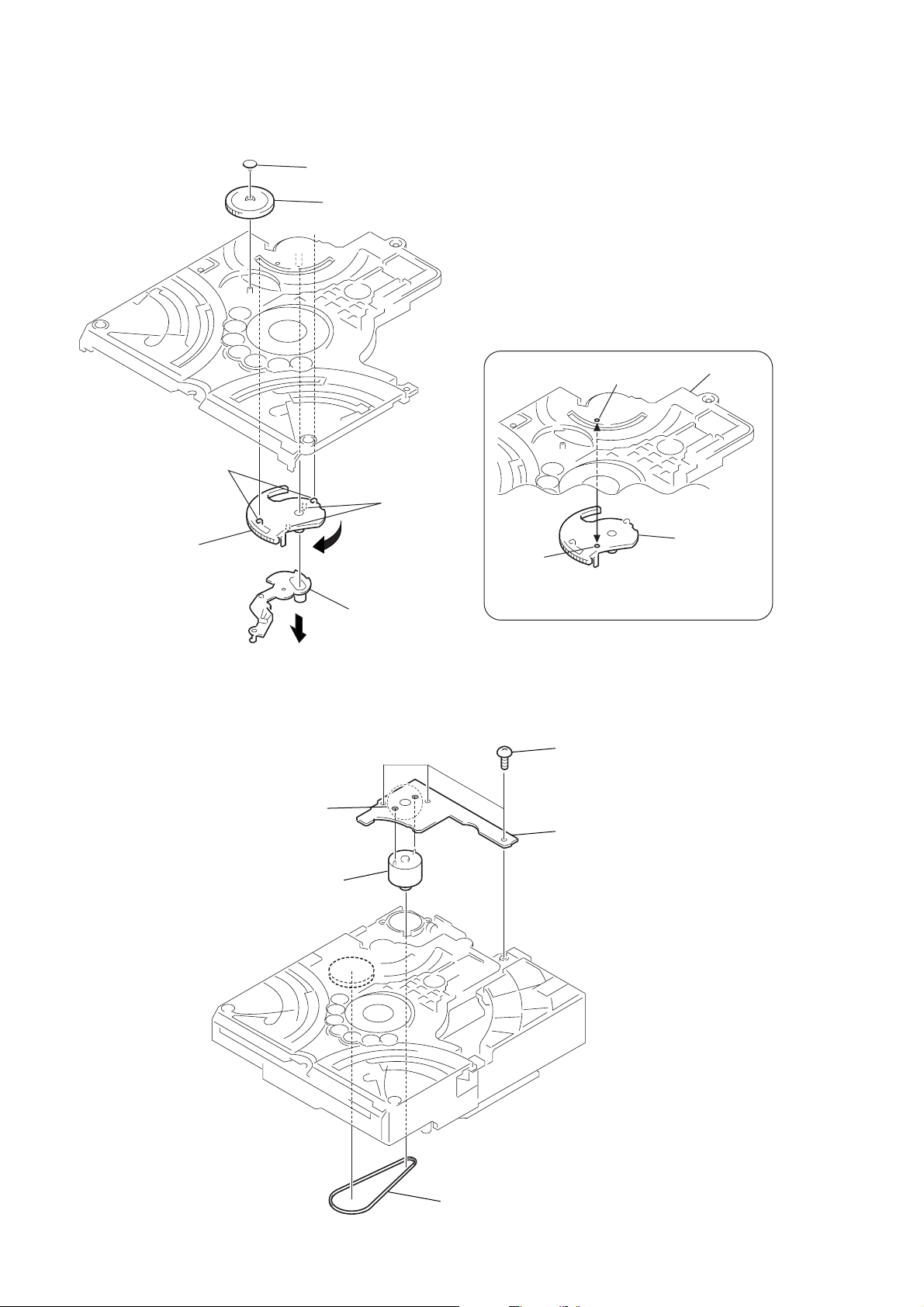
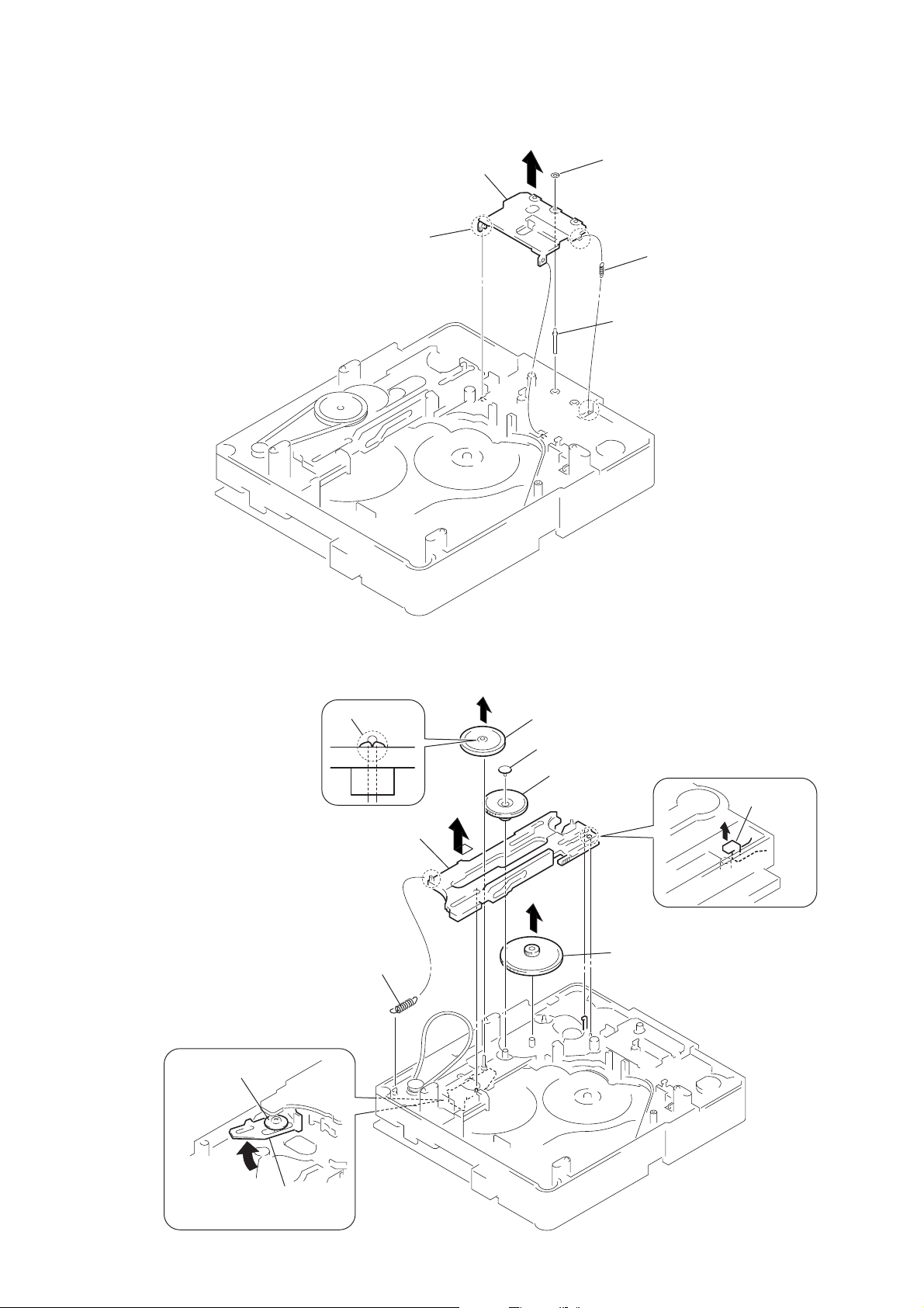
3-11. DISC STOP LEVER, DISC SENSOR LEVER
1
gear (cap)
2
gear (IDL L)
PRECAUTION DURING DISC STOP LEVER INSTALLATION
5
two hooks
6
disc stop lever
3-12. DRIVER BOARD
3
Remove soldering
from the two points.
3
two claws
4
disc sensor lever
hole
hole
Install the disc stop lever so that the both holes
are aligned.
2
three screws
(+BVTP 2.6
5
DRIVER board
chassis (top)
disc stop lever
×
8
16
4
motor (pully) assy
1
belt (MOT)
3-13. RF BOARD
4
wire (flat type)
(CN002)
5
RF board
HCD-SC5/SC6/SC8
3
wire (flat type)
(CN001)
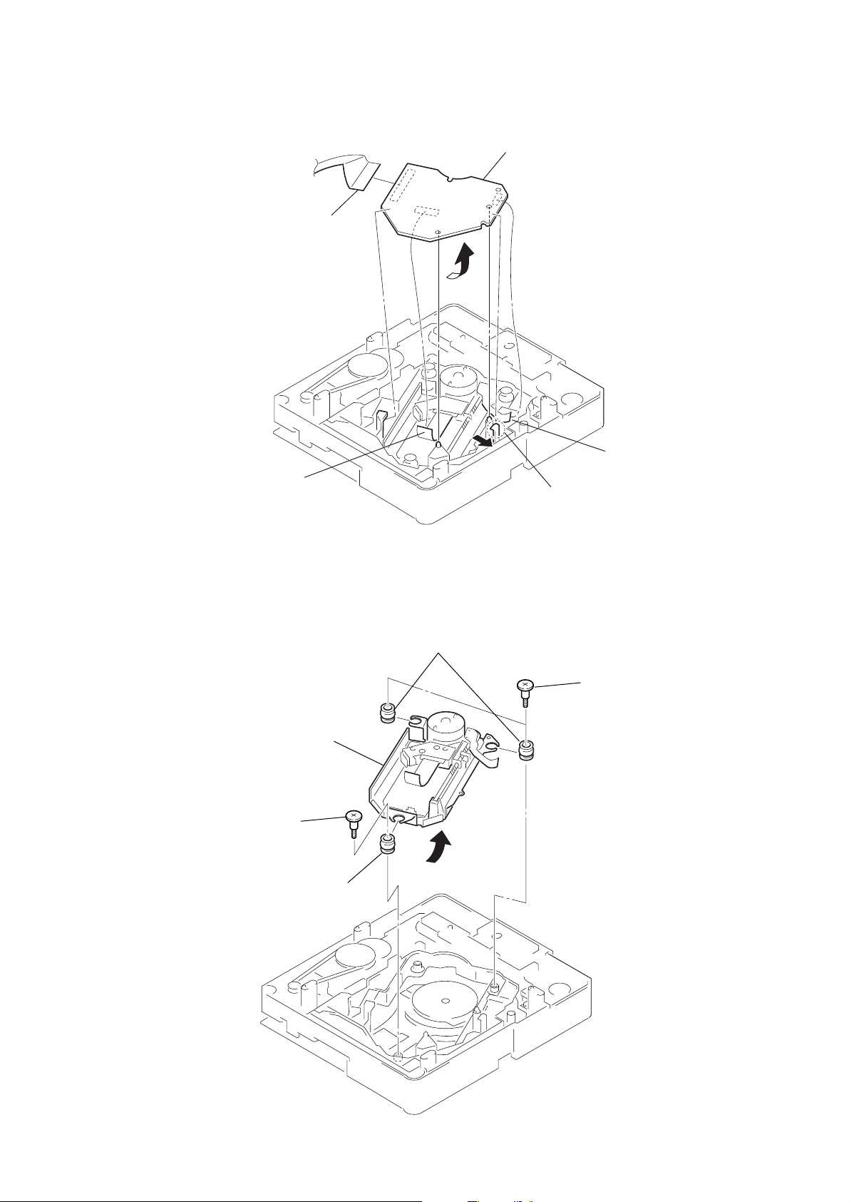
3-14. OPTICAL PICK-UP (TDP022W)
5
optical pick-up
(TDP022W)
2
step screw (M)
3
two insulators
1
2
wire (flat type)
(CN003)
claw
1
two step screws (M)
4
insulator
17
HCD-SC5/SC6/SC8
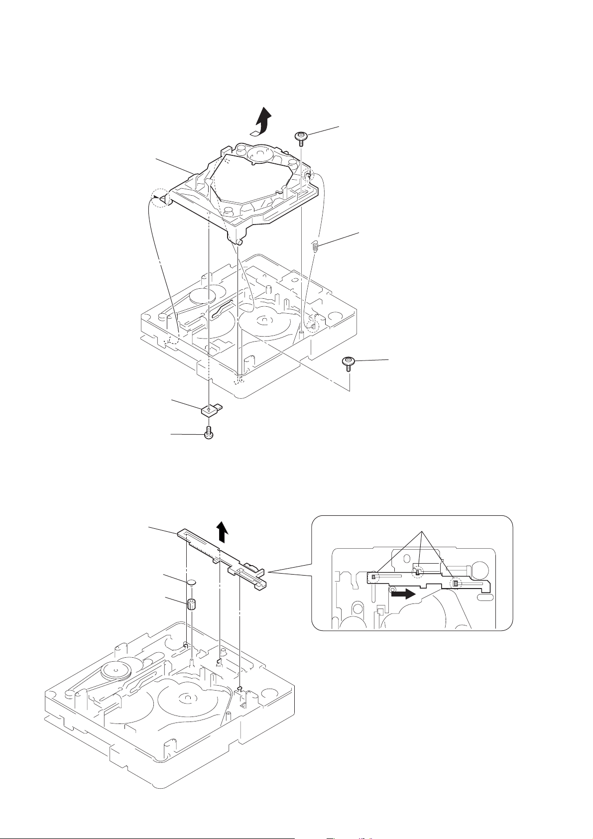
3-15. BASE UNIT
6
base unit
4
floating screw
(+PTPWHM 2.6)
3
holder down spring
2
lever (CL UP2)
1
screw
(+BVTP 2.6
3-16. LEVER (BU LOCK)
4
lever (BU lock)
1
gear (cap)
2
gear (BU lock)
5
floating screw
(+PTPWHM 2.6)
×
8)
3
three hooks
2
18
3-17. CLOSE LEVER
g
3
5
claw
close lever
1
washer (3-1-0.4)
2
4
shaft disc stop
HCD-SC5/SC6/SC8
close lever sprin
3-18. DIR LEVER, GEAR (IDL-B)
1
6
Loosen the screw.
2
claw
9
DIR lever
DIR spring
3
gear puley
4
gear (cap)
5
gear (IDL-A)
q;
gear (IDL-B)
8
stoper
7
Hold the release lever
and change the direction.
19
HCD-SC5/SC6/SC8
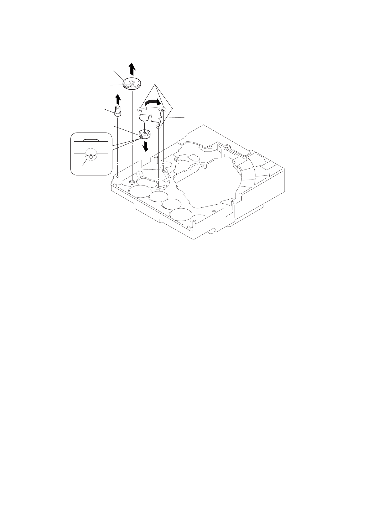
3-19. GEAR (IDL-C)
3
gear (IDL-D)
2
two claws
1
gear (IDL-F)
7
gear (IDL-C)
6
claw
4
three hooks
5
gear loading lever
20
SECTION 4
TEST MODE
HCD-SC5/SC6/SC8
[Version Display Mode]
*The software version is displayed.
Procedure:
1. Press three b uttons of [FUNCTION], x and A simultaneously
for two seconds.
2. The message “VERSION” is displayed. The version display
mode is activated.
3. Press the NEXT > button. “IF ***” is displayed.
4. Each time the NEXT > button is pressed, the display
changes in the order of DVD, AREA, VERSION and IF.
5. To exit from this mode, press the ?/1 button.
[Key T est Mode]
* Button check
Procedure:
1. Press three buttons of [DISPLAY], [FUNCTION] and A
simultaneously.
2. The message “KEY NUM 0” is displayed and “0” blinks.
3. Each time a button is pressed, “KEY NUM 0” v alue increases.
However, once a button is pressed, it is no longer taken into
account.
4. When all buttons are pressed, “KEY NUM 15” appears and
the number blinking is stopped.
5. To exit from this mode, disconnect the power cord.
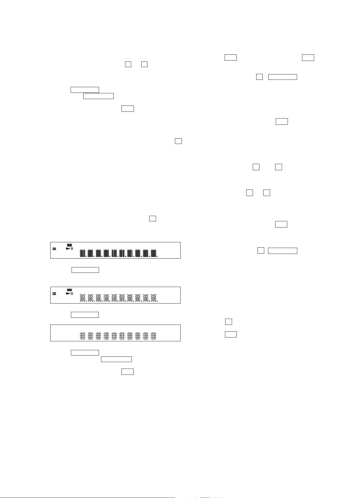
[Display T est Mode]
Procedure:
1. Press three buttons of [BAND], [DISPLAY] and A
simultaneously.
2. All segments are turned on.
dts
SACD MULTI ST NIGHT ALBMTITLESLEEP TRK CHAP INDEX H TUNED M MONO S
DIGITAL
D
D
DOLBY PLII FMAM
PCMMP3ALL1DISC S
3. When the NEXT > button is pressed, the display will light
up as follows.
dts
SACD MULTI ST NIGHT ALBMTITLESLEEP TRK CHAP INDEX H TUNED M MONO S
DIGITAL
D
D
DOLBY PLII FMAM
PCMMP3ALL1DISC S
4. Press the NEXT > button and confirm the display.
kHz BASS SHUF
MHz PBC PROG
NTSC REP1
kHz BASS SHUF
MHz PBC PROG
NTSC REP1
[OSD Test Mode]
Procedure:
1. Press the ?/1 button on the main unit or the ?/1 button on
the remote commander to turn the set on.
2. Set the FUNCTION to DVD.
3. Press three buttons of A , . PREV and [VOLUME+]
simultaneously.
4. The message “SERVICE IN” is displayed on the display. The
Test Mode Menu is displayed on the TV screen.
5. To execute each function, select the number on the remote
commander.
6. See the following section for explanation in detail.
7. To exit from this mode, press the ?/1 button.
[Disc Slot Lock]
The disc slot lock function for the antitheft of an demonstration
disc in the store is equipped.
Setting Procedure:
1. Turn the set on.
2. Press two buttons of x and A simultaneously for five
seconds.
3. The message “LOCKED” is displayed and the slot is locked.
Releasing Procedure:
1. Press two b uttons of x and A simultaneously for fiv e seconds
again.
2. The message “UNLOCKED” is displayed and the slot is
unlocked.
Note : When “LOCKED” is displayed, the slot lock is not released
by turning power on/off with the ?/1 button.
[Repeat Limit Release Mode]
Procedure:
1. Press three buttons of A , . PREV and [VOLUME-]
simultaneously.
2. Repeat limit is released.
[CDM Ship Mode]
*This mode moves the optical pick-up to the position durable to
vibration. Use this mode when returning the set to the customer
after repair.
Procedure:
1. Turn the set on.
2. Set the function to DVD.
3. Press the x button for five seconds.
4. The message “MECHA LOCK” is displayed.
5. Press the ?/1 button to turn off. The CDM ship mode is set.
5. Press the NEXT > button, all segments are turned off.
6. Every pressing of the NEXT > button turns on each
segments in the same order.
7. To exit from this mode, press the ?/1 button.
21

HCD-SC5/SC6/SC8
[GENERAL DESCRIPTION]
The T est Mode allows you to make diagnosis and adjustment easil y
using the remote commander and monitor TV. The instructions,
diagnostic results, etc. are given on the on-screen display (OSD).
[TEST DISC LIST]
Use the following test disc on test mode.
TDV-520CSO (DVD-SL): PART No. J-2501-236-A
LUV-P01 (CD): PART No. 4-999-032-01
TDV-540C (DVD-DL): PART No. J-2501-235-A
Note: Do not use exiting test disc for DVD.
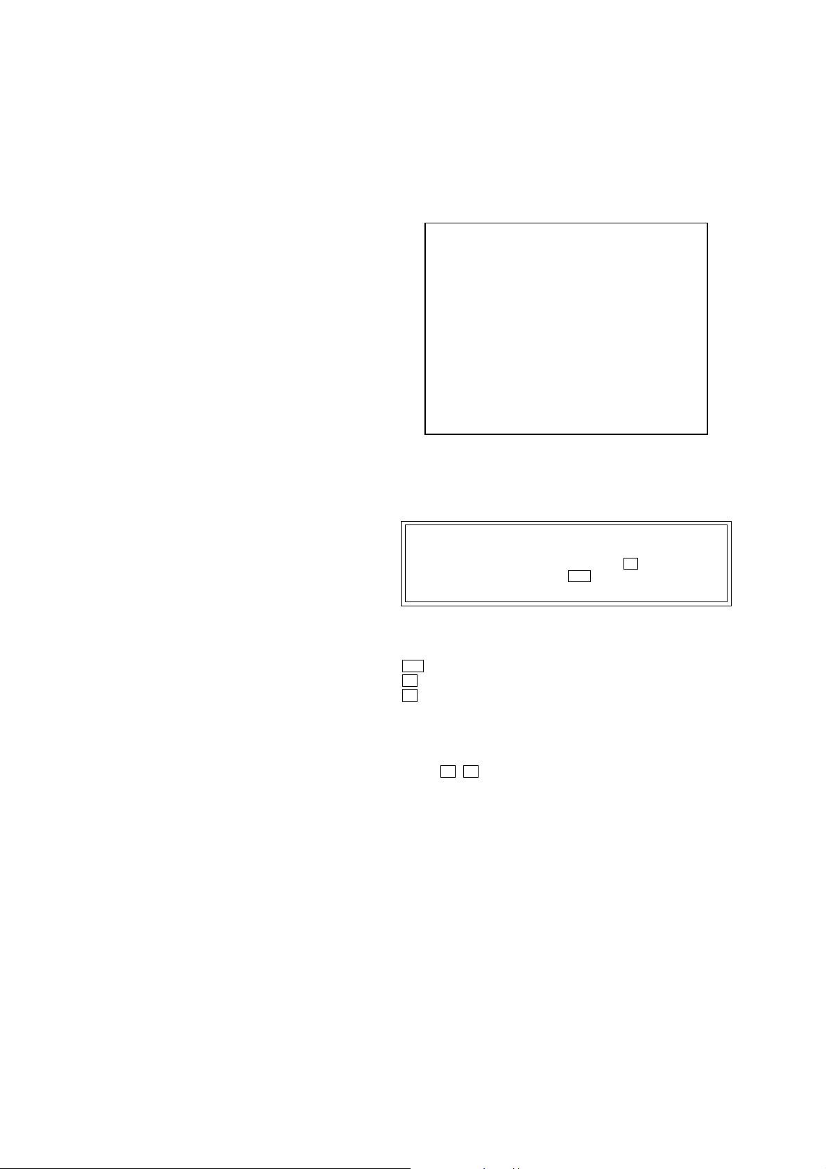
[STARTING TEST MODE]
1. Press the @/1 button to turn the power on, and set the function
to DVD.
2. Press three buttons of Z , . PREV and [VOLUME+]
simultaneously to enter the test mode.
3. It displays “SERVICE IN” on the fluorescent indicator tube,
and displays the Test Mode Menu on the monitor screen as
follows. (At the bottom of the menu screen, the model name
and revision number are displayed)
Test Mode Menu
0. Syscon Diagnosis
1. Drive Auto Adjustment
2. Drive Manual Operation
3. Mecha Aging
4. Emergency History
5. Mecha Error History
6. Version Information
7. Video Level Adjustment
Exit: POWER Key
Model :DAV-SCX xx
Revision :x.xx
4. To execute each function, select the desired menu and press its
number on the remote commander (RM-SP800).
5. To release from test mode, press the @/1 button and turn the
power off.
[OPERATING TEST MODE]
0. SYSCON DIAGNOSIS
The same contents as board detail check by serial interface can be
checked from the remote commander operation.
On the Test Mode Menu screen, press [10/0] key on the remote
commander, and the following Check Menu will be displayed.
### Syscon Diagnosis ###
Check Menu
0. Quit
1. All
2. Version
3. EEPROM
4. GPIO
5. SD Bus
6. Video
0-1. All (All items continuous check)
This menu checks all diagnostic items continuously. Normally, all
items are checked successively one after another automatically
unless an error is found, but at a certain item that requires judgment
through a visual check to the result, the following screen is displayed
for the key entry.
• Example display
### Syscon Diagnosis ###
Diag All Check
No.2 Version
2-3. ROM Check Sum
Check Sum = 7906
Press NEXT Key to Continue
Press PREV Key to Repeat
For the ROM Check, the check sum calculated by the Syscon is
output, and therefore you must compare it with the specified value
for confirmation.
Following the message, press the [NEXT ] button to go to the
next item, or press the [ PREV] button to repeat the same
operation again.
To quit the diagnosis and return to Check Menu screen, press the
.
>
[RETURN] key on the remote commander to display Check Menu.
• Error occurred
If an error occurred, the diagnosis is suspended and error is displayed.
Press the [RETURN] key on the remote commander to quit the
diagnosis, or press the [ PREV] button to repeat the same check
where an error occurred, or press the [NEXT ] button to continue
the check from the item next to faulty item.
General Description of Checking Method
Selecting 2 and subsequent items calls the submenu screen of each
item. And selecting 2 and subsequent items executes respective
menus and outputs the results.
For the contents of each submenu, see “Check Items List” as below .
Check Items List:
0-2. Version
0-2-1. All
0-2-2. Revision
0-2-3. ROM Check Sum
0-2-4. Model Type
0-2-5. Region
0-3. EEPROM Check
0-3-1. Sampling Check
0-3-2. Detail Check
0-4. GP I/O Check
0-5. SD Bus Check
0-6. Video Check
.
>
0-0. Quit
Quit the Syscon Diagnosis and return to the Test Mode Menu.
22
0-2. Version
0-2-2. Revision
The revision number of ROM (IC205) tha t the program for
the DVD system processor (IC206) is stored.
0-2-3. ROM Check Sum
Check sum is calculated. (4 digits hexadecimal number)

HCD-SC5/SC6/SC8
0-2-4. Model Type
Model name is displayed. (DAV-SCX)
0-2-5. Region
Model destination code is displayed. (2 digits number)
0-3. EEPROM Check
0-3-1. Sampling Check
EEPROM check at every 64 words.
It compares read data with write data of each address. When
there are discrepancies between two data, it displays error.
0-3-2. Detail Check
EEPROM check at every 1 word.
It compares read data with write data of each address. When
there are discrepancies between two data, it displays error.
0-4. GP I/O Check
Pull up/down setting check of the DVD system processor (IC206)
pin 150, 151 and 154 (for clock setting port).
0-5. SD Bus Check
SD bus data check between DVD decoder (IC701) and D-RAM
(IC706).
0-6. Video Check
Output the color bars for video level adjustment.
1. DRIVE AUTO ADJUSTMENT
On the Test Mode Menu screen, press the [1] key on the remote
commander, and the Adjustment Menu will be displayed.
## Drive Auto Adjustment ##
Adjustment Menu
0. ALL
1. DVD-SL
2. CD
3. DVD-DL
1-1. DVD-SL (single layer)
Press the 1 key on the remote commander and insert a D VD single
layer disc following the message. Then the adjustment will be made
through the steps below, then adjusted values will be written to the
EEPROM.
DVD Single Layer Disc Adjustment Steps:
1. Sled tilt reset
2. Disc check memory SL
3. Wait 300 msec
4. Set disc type SL
5. LD on
6. Spindle start
7. Wait 1 sec
8. Focus servo on 0
9. Auto track offset adjust
10. CLVA on
11. Wait 500 msec
12. Tracking on
13. Wait 1 sec
14. Sled on
15. Check CLV on
16. Auto LFO adjust
17. Auto focus offset adjust
18. Auto tilt position adjust
19. Auto focus gain adjust
20. Auto focus offset adjust
21. EQ boost adjust
22. Auto loop filter offset adjust
23. Auto track gain adjust
Search Check
24. 32 track jump forward
25. 32 track jump reverse
26. 500 track jump forward
27. 500 track jump reverse
28.All servo stop
29.EEP copy loop filter offset
1-2. CD
Press the [2] key on the remote commander and insert a CD disc
following the message. Then the adjustment will be made through
the steps below , then adjusted values will be written to the EEPR OM.
Exit: RETURN
Normally, [10/0] is selected to adjust DVD (single layer), CD and
DVD (dual layer) in this order . But, individual items can be adjusted
for the case where adjustment is suspended due to an error. In this
mode, the adjustment can be made easily through the operation
following the message displayed on the screen.
The disc used for adjustment must be the one specified for
adjustment.
1-0. ALL
Press the [10/0] key on the remote commander, and the servo set
data in EEPROM will be initialized. Then, 1. DVD-SL disc, 2. CD
disc and 3. DVD-DL disc are adjusted in this order.
Each time one disc was adjusted, it is ejected. Replace it with the
specified disc following the message. You can f inish the adjustment
by pressing the [RETURN] button on the remote commander.
Note: During adjustment of each disc, the measurement for disc type judg-
ment is made. As automatic adjustment does not judge the disc
type unlike conventional models, take care not to insert wrong type
discs. Also, do not give a shock during adjustment.
CD Adjustment Steps
1. Sled tilt rest
2. Disc check memory CD
3. Wait 500 msec
4. Set disc type CD
5. LD on
6. Spindle start
7. Wait 500 msec
8. Focus servo on 0
9. Auto track offset adjust
10. CLVA on
11. Wait 500 msec
12. Tracking on
13. (TC display start)
14. Wait 1 sec
15. Jitter display start
16. Sled ON
17. Check CLV on
18. Auto loop filter offset adjust
19. Auto focus offset adjust
20. Auto focus gain adjust
21. Auto focus offset adjust
22. EQ boost adjust
23. Auto LFO Adjust
23
HCD-SC5/SC6/SC8
24. Auto track gain adjust
Search Check
25. 32Tj forward
26. 32Tj reverse
27. 500Tj forward
28. 500Tj reverse
29. All servo stop
1-3. DVD-DL (dual layer)
Press the [3] key on the remote commander and insert a DVD dual
layer disc following the message. Then the adjustment will be made
through the steps below, then adjusted values will be written to the
EEPROM.
DVD Dual Layer Disc Adjustment Steps:
1. Sled tilt reset
2. Disc check memory DL
3. Wait 500 msec
4. Set disc type DL
5. LD on
6. Spindle start
7. Wait 1 sec
Layer 1 Adjust
8. Focus servo on 0
9. Auto track offset adjust
10. CLVA on
11. Wait 500 msec
12. Tracking on
13. Wait 500 msec
14. Sled on
15. Check CLV lock
16. Auto loop filter offset adjust, Auto focus adjust
17. Auto focus gain adjust
18. Auto focus offset adjust
19. EQ boost adjust
20. Auto loop filter offset adjust
21. Auto Track Gain Adjust
Search Check
22. 32 track jump forward
23. 32 track jump reverse
24. 500 track jump forward
25. 500 track jump reverse
Layer 0 Adjust
26. Focus jump (L1 t L0)
27. Auto track offset adjust L0
28. CLVA on
29. Wait 500 msec
30. Tracking on
31. Wait 500 msec
32. Sled on
33. Check CLV lock
34. Auto focus filter offset adjust
35. Auto Focus Adjust
36. Auto focus gain adjust
37. Auto focus offset adjust
38. EQ boost adjust
39. Auto Loop Filter Offset
40. Auto track gain adjust
Search Check
41. 32 track jump forward
42. 32 track jump reverse
43. 500 track jump forward
44. 500 track jump reverse
Layer Jump Check
45. Layer jump (L0 ? L1)
46. Layer jump (L1 ? L0)
47. All servo stop
2. DRIVE MANUAL OPERATION
Note: This mode is used for design, and not used in service fundamen-
tally.
On the Test Mode Menu screen, press the [2] key on the remote
commander, and the Operation Menu will be displayed. For the
manual operation, each servo on/off control and adjustment can be
executed manually.
## Drive Manual Operation ##
Operation Menu
1. Disc Type
2. Servo Control
3. Track/Layer Jump
4. Non EEPROM Write Adjust
5. EEPROM Write Adjust
6. Memory Check
7. Disc Check Memory
8. Error Rate Display
9. SACD Water Mark
Exit: RETURN
In using the manual operation menu, take care of the following
points. These commands do not provide protection, thus requiring
correct operation. The sector address or time code field is displayed
when a disc is loaded.
Note:
1. Set correctly the disc type to be used on the Disc Type screen.
2. In case of an alar m, immediately press the x button to stop the
servo operation, and press the @/1 button to turn the power of f.
Basic operation:
(controllable from front panel or remote commander)
@/1 :Power OFF (release the Test Mode)
x : Servo stop
A : Stop and eject
[RETURN] : Return to Operation Menu or Test
Mode Menu
[ PREV], [NEXT ] :Transition between sub modes of menu
>.
[1] to [9], [10/0] : Selection of menu items
Cursor o/
O
: Increase/Decrease in manually
adjusted value
24

HCD-SC5/SC6/SC8
2-1. Disc Type
Disc Type
Disc Type Select
1. Disc Type Auto Check
2. Set Disc Type DVD
3. Set Disc Type CD
4. Set Disc Type Hybrid
Exit: RETURN
2-1-1. Disc Type Auto Check
1) Press the [1] key on the remote commander to display the Disc
Type Auto Check screen.
2) Insert a disc and press the [ENTER] key on the remote
commander.
3) It judges the type of inserted disc automatically and displays
the disc type and so on as below.
Disc Type Auto Check
Disc Type xx
Layer xx
Mirr Time xx
Mirr Count xx
FZC Count xx
PI Reference xx
PI Peak xx
2-1-3. Disc Type CD
It sets up so that it may judge as a disc type of specification of the
disc with which the set was inserted.
[1]: CD disc (normal speed, 12 cm)
[2]: CD disc (double speed, 12 cm)
[3]: CD disc (normal speed, 8 cm)
[4]: CD disc (double speed, 8 cm)
[5]: CD-RW disc (normal speed, 12 cm)
[6]: CD-RW disc (double speed, 12 cm)
[7]: CD-RW disc (normal speed, 8 cm)
[8]: CD-RW disc (double speed, 8 cm)
2-1-4. Disc Type Hybrid
It sets up so that it may judge as a disc type of specification of the
disc with which the set was inserted.
[1]: SACD Hybrid disc (SACD layer, 12 cm)
[2]: SACD Hybrid disc (CD layer, normal speed, 12 cm)
[3]: SACD Hybrid disc (CD layer, double speed, 12 cm)
[4]: SACD Hybrid disc (SACD layer, 8 cm)
[5]: SACD Hybrid disc (CD layer, normal speed, 8 cm)
[6]: SACD Hybrid disc (CD layer, double speed, 8 cm)
2-2. Servo Control
Note: Be sure to perform the disc type setup before performing this item.
Servo Control
1.LD off R.Sled FWD
2.Focus off L.Sled REV
3.SPDL off U.Sled Reset
4.CLVA off D.Sled Limit
5.Trk. off
6.Sled off
7.Fcs.Srch off
ENTER.Execute
Exit: RETURN
Disc Type : CD, DVD or Hybrid (SACD)
Layer : SINGLE, DUAL or HYBRID
Mirr Time : Mirror time of between disc surface and record
surface when disc type judgment. (hexadecimal
number)
Mirr Count : The number of times which mirror counts between
disc surface and record surface when disc type
judging. (hexadecimal number)
FZC Count : The number of times which focus zero cross points
of each layer when lens down. (hexadecimal number)
PI Reference : The average of PI reference voltage. (hexadecimal
number)
PI Peak : PI peak level voltage. It performs only when disc
type judgment is successful. (hexadecimal number)
2-1-2. Disc Type DVD
It sets up so that it may judge as a disc type of specification of the
disc with which the set was inserted.
[1]: DVD single layer disc (12 cm)
[2]: DVD dual layer disc (0 layer, 12 cm)
[3]: DVD dual layer disc (1 layer, 12 cm)
[4]: DVD-RW disc (12 cm)
[5]: DVD single layer disc (8 cm)
[6]: DVD dual layer disc (0 layer, 8 cm)
[7]: DVD dual layer disc (1 layer, 8 cm)
0.All Servo Off
Exit: RETURN
On this screen, the servo on/off control necessary for replay is
executed. Normally, turn on each servo from 1 sequentially and
when CLVA is turned on, the usual trace mode becomes active. In
the trace mode, DVD sector address or CD time code is displayed.
This is not displayed where the spindle is not locked.
The spindle could run overriding the control if the spindle system is
faulty or RF is not present. In such a case, do not operate CLVA.
[1] LD : Turn on/off the laser.
[2] Focus : Search the focus and turn on the focus.
[3] SPDL :Turn on/off the spindle.
[4] CLVA : Turn on/off normal servo of spindle servo.
[5] Trk. : Turn on/off the tracking servo.
[6] Sled : Turn on/off the sled servo.
[7] FCS. Srch : Turn on/off the focus search.
[8] FCS. OppL : Turn on/off the focus search to another layer
of designated layer in Disc T ype setting. (dual
layer disc only)
[10/0] : All servo off.
[R] Sled FWD (right cursor) : Move the sled forward.
[L] Sled REV (left cursor) :Move the sled reverse.
[U] Sled FWD (up cursor) : Reset the sled.
[D] Sled REV (down cursor): Limit in the sled.
25

HCD-SC5/SC6/SC8
2-3. Track/Layer Jump
Track/Layer Jump
1. 1Tj FWD R.Lj L0>L1
2. 1Tj REV L.Lj L1>L0
3.500Tj Fine FWD U.Fj L0>L1
4.500Tj Fine REV D.Fj L1>L0
5.10kTj Dirc FWD
6.10kTj Dirc REV
7.20kTj Dirc FWD
8.20kTj Dirc REV
0. All Servo Off
Exit: RETURN
On this screen, track jump, etc. can be performed. Only for the DVD
dual layer disc, the focus jump and layer jump are displayed in the
right field
[1] 1Tj FWD : 1 track jump forward.
[2] 1Tj REV : 1 track jump reverse.
[3] 500Tj FWD: 500 track jump (fine search)forward.
[4] 500Tj REV : 500 track jump (fine search) reverse.
[5] 10kTj FWD: 10k track jump (direct search) forward.
[6] 10kTj REV : 10k track jump (direct search) reverse.
[7] 20kTj FWD: 20k track jump (direct search) forward.
[8] 20kTj REV : 20k track jump (direct search) reverse.
[10/0] : All servo off.
2-4. Non EEPROM Write Adjust
Non EEPROM Write Adjust
1. Focus Offset
2. Focus Gain
3. Trk. Offset Coarse
4. Trk. Offset Fine
5. Trk. Gain
6. EQ Boost
0.All Servo Off
Exit: RETURN
2-5. EEPROM Write Adjust
EEPROM Write Adjust
1. Focus Offset
2. Focus Gain
3. Trk. Offset Coarse
4. ——————
5. Trk. Gain
6. EQ Boost
0.All Servo Off
Exit: RETURN
On this screen, each item can be adjusted automatically. Select the
desired number [1] to [10/0] from the remote commander, and
selected item is adjusted automatically .
[1] Focus Offset: Adjusts focus offset.
[2] Focus Gain : Adjusts focus gain.
[3] TRK. Offset : Adjusts tracking offset of the RF amp
(IC001) side.
[5] TRK. Gain : Adjusts track gain.
[6] EQ Boost : Adjusts amount of boost of equalizer.
[10/0] : All servo off.
2-6. Memory Check
Display images are shown as follows, and all two screens are able
to switch by theOkey (UP) or okey (DW).
EEPROM Data 1/2 CD SL L0 L1
Focus Gain xx xx xx xx
Trk. Gain xx xx xx xx
Focus Offset xx xx xx xx
Trk. Offset xx xx xx xx
EQ. Boost xx xx xx xx
PI Level xx xx -- -Fcs. Balance -- xx -- -Jitter xx xx xx xx
Mirror Time xx xx xx -FE Level -- xx -- -Traverse Lv1. -- xx -- -Next:DW Default:CLR Exit:RET
On this screen, each item can be adjusted manually. Select the desired
number [1] to [10/0] from the remote commander, and current
setting for the selected item will be displayed, then increase or
decrease numeric value with theOkey or okey. This value is
stored in the EEPROM. If CLV has been applied, the jitter is
displayed for reference for the adjustment.
[1] Focus Offset: Adjusts focus offset.
[2] Focus Gain : Adjusts focus gain.
[3] TRK. Offset : Adjusts tracking offset of the RF amp
(IC001) side.
[4] TRK. Offset : Adjusts tracking offset of the DSP (IC401)
side.
[5] TRK. Gain : Adjusts track gain.
[6] EQ Boost : Adjusts amount of boost of equalizer.
[10/0] : All servo off.
26
EEPROM Data 2/2 CDRW DVDRW
Focus Gain xx xx
Trk. Gain xx xx
Focus Offset xx xx
Trk. Offset xx xx
EQ. Boost xx xx
Prev:UP Default:CLR Exit:RET
On this screen, current servo adjusted data stored in the EEPROM
are displayed. The adjusted data are initialized by pressing the
[CLEAR] key, but be careful that they are not recoverable after
initialization.
Before clearing the adjusted data, make a note of the set data. This
screen will also appear if [0]-All is selected in the Drive Auto
Adjustment. In this case, default setting cannot be made.

HCD-SC5/SC6/SC8
2-7. Disc Check Memory
Disc Check Memory
1. SL Disc check
2. CD Disc check
3. DL Disc check
Exit: RETURN
On this screen, measure the mirror time of chucked disc, and write
to the EEPROM.
2-8. Error Rate Display
Error Rate Display
UC CR Address
PI1 Err Now xx xxxx xxxxxxxx
Max xx xxxx xxxxxxxx
Avg xx xxxx
PI2 Err Now xx xxxx xxxxxxxx
Max xx xxxx xxxxxxxx
Avg xx xxxx
PO Err Now xx xxxx xxxxxxxx
Max xx xxxx xxxxxxxx
Avg xx xxxx
Start:ENTER Exit: RETURN
On this screen, measure and display the error rate.
UC : Incor rect value
CR : Correct value
2-9. SACD Water Mark Check
SACD Water Mark Check
PSP AMP
PSN
Start: ENTER Exit: RETURN
On this screen, measure the PSP AMP v alue and PSN value of SACD
water mark.
3. EMERGENCY HISTORY
On the Test Mode Menu screen, selecting [4] displays the
information such as servo emergency history.
The history information from last 1 up to 10 can be scrolled with
theOkey orokey. Also, specific information can be displayed
by directly entering that number with ten keys.
### EMG. History ###
Laser Hours CD xxxxhxxm
DVD xxxxhxxm
a. bb xx xx xx xx xx xx xx
xx xx xx xx xx xx xx xx
a. bb xx xx xx xx xx xx xx
xx xx xx xx xx xx xx xx
Select:1-9 Scroll:UP/DOWN
(1.Latest EMG.) Exit: RETURN
xxxxhxxm: The laser on total hours. Data below minutes are
omitted.
a. : Error number.
bb : Error code.
xx : Not used.
• Clearing History Information
Clearing laser hours:
Press the [DVD DISPLAY] and [CLEAR] keys in this order.
Then both CD and DVD data are cleared.
Clearing emergency history:
Press the [DVD TOP MENU] and [CLEAR] keys in this order .
Initializing set up data:
Press [DVD MENU] and [CLEAR] keys in this order.
The data have been initialized when “EEPROM Initialize
Finished.”. message is displayed. The EMG. History screen
will be restored soon.
• Code list of Emergency History
10: Communication to RF AMP (IC001) failed.
11: Each servo for focus, tracking, and spindle is unlocked.
12: Check sum error of EEPROM (IC203).
14: Communication to servo DSP (IC401) failed, or servo DSP
(IC401) is faulty.
15: Communication to DVD decoder (IC701) failed, or DVD
decoder (IC701) is faulty.
16: Communication to DSD decoder (IC801) failed, or DSD
decoder (IC801) is faulty.
20: Initialization of sled servo failed. It is not placed in the ini-
tial position.
23: Sled servo operation error.
24: Made a request to move the sled servo to wrong position.
30: Tracking balance adjustment error.
31: Tracking gain adjustment error.
33: Focus bias adjustment error.
34: Focus gain adjustment error.
35: Equalizer adjustment error.
40: Focus servo does not operate.
41: With a DVD dual layer disc, focus jump failed.
50: CLV (spindle) servo does not operate.
51: Spindle does not stop.
60: Made a request to seek nonexistent address.
61: Seek error of retry more than regulated times.
70: Control data could not be read.
80: Disc reading failed.
27

HCD-SC5/SC6/SC8
4. MECHA ERROR HISTORY
On the T est Mode Menu screen, selecting [5] displays the information
of mechanism deck error history.
The history information from last 1 up to 8 can be scrolled with the
key orokey. Also, specific information can be displayed by
O
directly entering that number with ten keys.
### Mecha Error History ###
1. aa bb cc dd xx xx xx xx
2. aa bb cc dd xx xx xx xx
3. aa bb cc dd xx xx xx xx
4. aa bb cc dd xx xx xx xx
5. aa bb cc dd xx xx xx xx
6. aa bb cc dd xx xx xx xx
7. aa bb cc dd xx xx xx xx
8. aa bb cc dd xx xx xx xx
Scroll:UP/DOWN
(1.Latest Err.) Exit: RETURN
aa : The error in the midst of initializing the mechanism deck.
bb : The error in the midst of loading operation.
cc : The error in the midst of up/down the stocker.
dd : The error in the midst of switching the mechanism deck mode.
xx : Not used.
• Error code (bb)
00 : Initializing the mechanism deck.
10 : Retry over of eject and loading.
30 : Open operation in no disc status.
60 : Retry over of eject and loading.
70 : Disc is chucking position.
81 : Retry failed of disc movement from chucking position to
stocker.
83 : Retry preparation failed of disc movement from chucking
position to stocker.
90 : Disc is stored in the stocker.
A1 : Retry failed of disc movement from stocker to chucking
position.
A3 : Retry preparation failed of disc movement from stocker to
chucking position.
B0 : Just before the release operation.
B1 : Retry failed of the release operation.
• Error code (cc)
10 : Under a stop.
22 : Retry preparation failed.
23 : Retry failed.
• Error code (dd)
10 : Under a stop.
22 : Retry preparation failed.
23 : Retry failed.
• Error code (aa)
FF : Complete the initializing. (normal operation)
11 : Stocker movement (to chucking position) failing in the midst
of initializing the mechanism deck.
12 : Stocker movement (to chucking position) failing in the midst
of initializing the mechanism deck.
1x : Initializing the mechanism deck.
2x : Initializing the mechanism deck.
3x : Initializing the mechanism deck.
41 : Disc eject failing in the midst of initializing the mechanism
deck.
4x : Initializing the mechanism deck.
50 : Disc eject failing in the midst of initializing the mechanism
deck.
5x : Initializing the mechanism deck.
A2 : Disc eject failing in the midst of initializing the mechanism
deck.
Ax : Initializing the mechanism deck.
D3 : Disc eject failing in the midst of initializing the mechanism
deck.
Dx : Initializing the mechanism deck.
Ex : Initializing the mechanism deck.
5. VERSION INFORMATION
On the Test Mode Menu screen, selecting [6] displays the ROM
version and region code.
The parenthesized hexadecimal number in version field is checksum
value of ROM.
## Version Information ##
IF con. Ver.x. xx
SYScon. Ver.x. xx (xxxx)
Model DAV-SCX
Region 0x
Config xxxxxxxx
Front End Ver.x.xx
Exit: RETURN
IF con. : The version of system controller (IC901).
SYScon. : The version of DVD system processor (IC206).
Front End: The version of mechanism controller (IC301).
6. VIDEO LEVEL ADJUSTMENT
On the Test Mode Menu screen, selecting [7] displays color bars
for video level adjustment. During display of color bars, OSD
disappears but the menu screen will be restored if pressing the
[RETURN] key.
28

SECTION 5
ELECTRICAL ADJUSTMENT
[TEST DISC LIST]
Use the following test disc on test mode.
TDV-520CSO (DVD-SL): PART No. J-2501-236-A
LUV-P01 (CD): PART No. 4-999-032-01
TDV-540C (DVD-DL): PART No. J-2501-235-A
Note: Do not use exiting test disc for DVD.
AUTO SERVO ADJUSTMENT
After parts related to the servo circuit (RF amplifier (IC001), DSP
(IC401), motor driver (IC501), EEPROM (IC302) so on) are
replaced, re-adjusting the servo circuit is necessary. Select “ALL”
at “1. DRIVE AUTO ADJUSTMENT” (Refer to page 23 in TEST
MODE) and adjust DVD-SL (single layer), CD and D VD-DL (dual
layer).
HCD-SC5/SC6/SC8
29
HCD-SC5/SC6/SC8
6-1. CIRCUIT BOARDS LOCATION
POWER LED board
SECTION 6
DIAGRAMS
DRIVER board
RF board
FL board
LF board
DVD board
DDCON board
SCART board
(only for AEP, UK and Russian models)
I/O board
AMP board
30
POWER board
HP board
 Loading...