

Sony HCD-SBT100, HCD-SBT300W, WB Schematic
HCD-SBT100/SBT100B/
SBT300W/SBT300WB
SERVICE MANUAL
Ver. 1.0 2013.06
Note:
Be sure to keep your PC used for service and
checking of this unit always updated with the
latest version of your anti-virus software.
In case a virus affected unit was found during
service, contact your Service Headquarters.
• HCD-SBT100 is the compact disc receiver in CMT-SBT100.
• HCD-SBT100B is the compact disc receiver in CMT-SBT100B.
• HCD-SBT300W is the compact disc receiver in CMT-SBT300W.
• HCD-SBT300WB is the compact disc receiver in CMT-SBT300WB.
Amplier section (North American model)
AUDIO POWER SPECIFICATIONS
POWER OUTPUT AND TOTAL HARMONIC
DISTORTION:
(The United States model only)
With 6 ohm loads, both channels driven, from
120 - 10,000 Hz; rated 20 watts per channel
minimum RMS power, with no more than 0.7%
total harmonic distortion from 250 milliwatts to
rated output.
Power output (rated): 20 watts + 20 watts
(at 6 ohms, 1 kHz, 1% THD)
RMS power output (reference): 25 watts + 25 watts
(per channel at 6 ohms, 1 kHz)
Amplier section (Other models)
Power output (rated):
HCD-SBT100/SBT100B:
20 watts + 20 watts (at 6 ohms, 1 kHz, 1% THD)
HCD-SBT300W/SBT300WB:
25 watts + 25 watts (at 6 ohms, 1 k Hz, 1% THD)
RMS power output (reference):
HCD-SBT100/SBT100B:
25 watts + 25 watts (per channel a t 6 ohms,
1kHz)
HCD-SBT300W/SBT300WB:
50 watts + 50 watts (per channel at 6 ohms,
1kHz)
Inputs/Outputs
AUDIO IN:
AUDIO IN (external input) jack:
Stereo mini jack, sensitivity 700 mV,
impedance 47 kilohms
(headphone) jack:
Stereo mini jack, 8 ohms o r more
USB:
Supported bit rate:
MP3 (MPEG 1 Audio Layer-3): 32 kbps - 3 20
kbps, VBR
WMA: 48 kbps - 192 kbps, VBR
AAC: 48 kbps -320 kbps
Sampling frequencies:
MP3 (MPEG 1 Audio Layer-3): 32/44.1/48 kHz
WMA: 44.1 kHz
AAC: 44.1 kHz
USB port:
Type A, 5 V DC 2.1 A
CD-DA/MP3 player section
System:
Compact disc and digital audio system
Laser Diode Properties:
Emission Duration: Continuous
Laser Output*: Less than 44.6 μW
* This output is the value measurement at a
distance of 200mm from the objective lens
surface on the Optical Pick-up Block with 7mm
aperture.
Frequency response:
50 Hz – 20 kHz
Signal-to-noise ratio:
More than 90 dB
Dynamic range:
More than 90 dB
Tuner section
AM tuner section
(HCD-SBT100/SBT300 W only):
Tuning range:
European models:
531 kHz – 1,602 kHz (with 9 kHz tuning
interval)
Other models:
530 kHz – 1,710 kHz (with 10 kHz tuning
interval)
531 kHz – 1,710 kHz (with 9 kHz tuning
interval)
Antenna:
AM loop antenna
Intermediate frequency:
400 kHz
FM tuner section:
FM stereo, FM superheterodyne tuner
North American model:
Tuning range:
87.5 MHz – 108.0 MHz (100 kHz step)
Other models:
Tuning range:
87.5 MHz – 108.0 MHz (50 kHz step)
Antenna:
FM lead antenna
DAB/DAB+ tuner section
(HCD-SBT100B/SBT300W B only):
FM stereo, DAB/FM superheterodyne tuner
Frequency range:
Band-III:
174.928 (5A) MHz – 239.200 (13F) MHz*
* For details, see “DAB/DAB+ frequency table”
below.
Antenna:
DAB/FM lead antenna:
The DAB/DAB+ services are available only in
countries/regions that support DAB/DAB+
services.
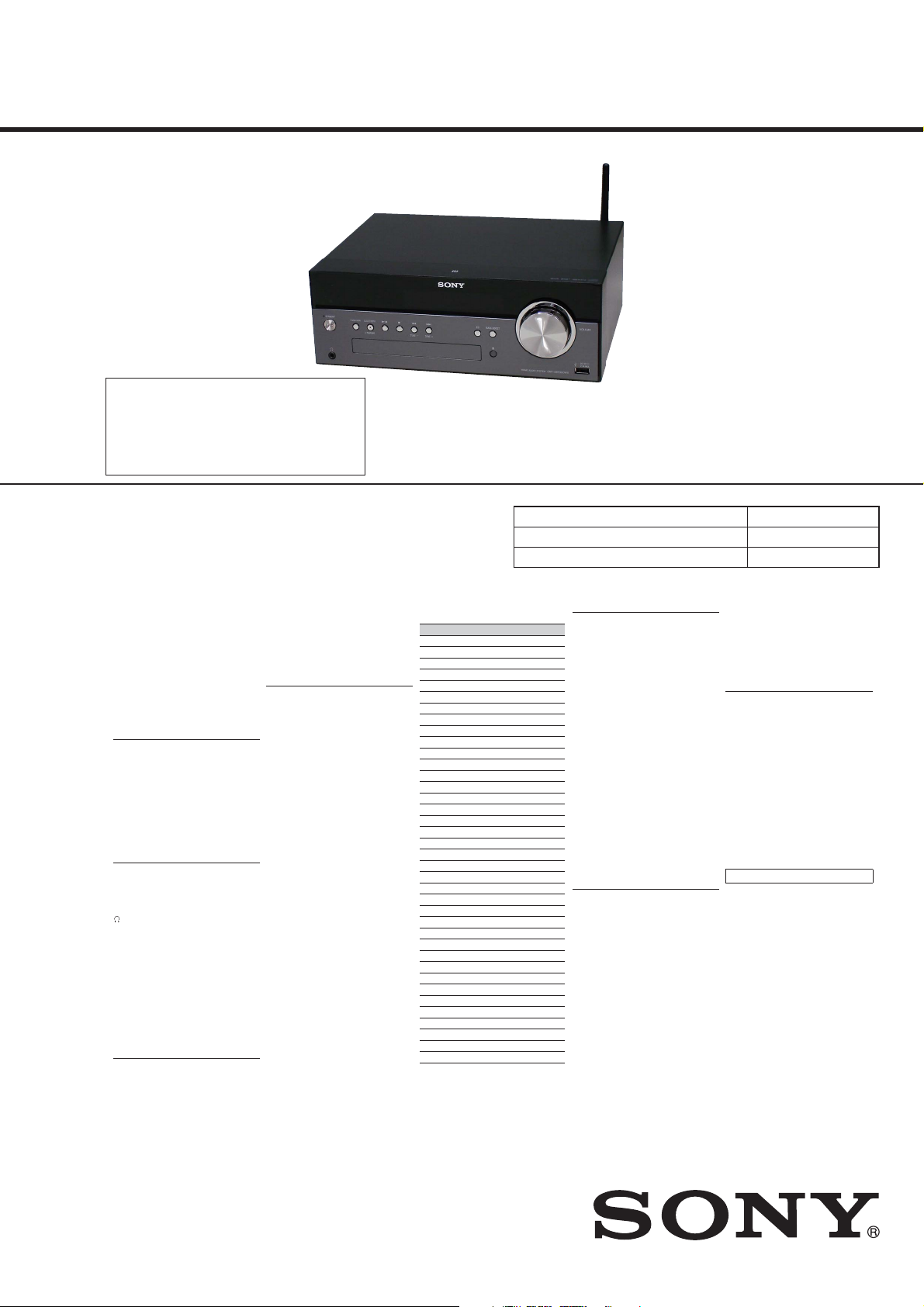
Photo: HCD-SBT300WB
SPECIFICATIONS
DAB/DAB+ frequency table (Band-III):
Frequency Label
174.928 MHz 5A
176.640 MHz 5B
178.352 MHz 5C
180.064 MHz 5D
181.936 MHz 6A
183.648 MHz 6B
185.360 MHz 6C
187.072 MHz 6D
188.928 MHz 7A
190.640 MHz 7B
192.352 MHz 7C
194.064 MHz 7D
195.936 MHz 8A
197.648 MHz 8B
199.360 MHz 8C
201.072 MHz 8D
202.928 MHz 9A
204.640 MHz 9B
206.352 MHz 9C
208.064 MHz 9D
209.936 MHz 10A
211.648 MHz 10B
213.360 MHz 10C
215.072 MHz 10D
216.928 MHz 11A
218.640 MHz 11B
220.352 MHz 11C
222.064 MHz 11D
223.936 MHz 12A
225.648 MHz 12B
227.360 MHz 12C
229.072 MHz 12D
230.784 MHz 13A
232.496 MHz 13B
234.208 MHz 13C
235.776 MHz 13D
237.488 MHz 13E
239.200 MHz 13F
* Frequencies are displa yed to two decimal
places on this system.
US Model
Canadian Model
HCD-SBT100
AEP Model
HCD-SBT100/SBT100B/
SBT300W/SBT300WB
UK Model
HCD-SBT100B/SBT300WB
Australian Model
HCD-SBT100/SBT300W/SBT300WB
Model Name Using Similar Mechanism NEW
CD Mechanism Type CDM90-DVBU202
Optical Pick-up Block Name CMS-S76RFS7G
BLUETOOTH section
Communication system:
BLUETOOTH Standard version 3.0
Output:
BLUETOOTH Standard Pow er Class 2
Maximum communication range:
Line of sight approx. 10 m
Frequency band:
2.4 GHz band (2.4000 GHz - 2.4835 GHz)
Modulation method:
FHSS
Compatible BLUETOOTH proles*2:
A2DP (Advanced Audio Distribution Prole)
AVRCP (Audio Video Remote Control Prole)
Supported content protection method
SCMS-T method
Transmission bandwidth
20 Hz – 20,000 Hz (with 44.1 kHz sampling)
1
*
The actual range will vary depending on factors
such as obstacles between devices, magnetic
fields around a microwave oven, static
electricity, reception sensitivity, antenna’s
performance, operating system, software
application, etc.
2
*
BLUETOOTH standard profiles indicate the
purpose of BLUETOOTH communication
between devices.
Network section
(HCD-SBT300/SBT300WB only)
LAN port:
RJ-45
10BASE-T/100BASE-TX
(The communication speed may vary
depending on the communication
environment. This system does not
guarantee the communication speed and
quality of 10BASE-T/100BASE-TX.)
*1
Wireless LAN:
Compatible standards:
IEEE 802.11 b/g (WEP 64 bit, WEP 128 bit)
Frequency band 2.4 GHz band (2.4000 GHz -
2.4835 GHz)
Available channels ch1 to ch13
WPA/WPA2-PSK (AES)
WPA/WPA2-PSK (TKIP)
General
Power requirements:
North American model:
AC 120 V, 60 Hz
Other models:
AC 220 V - 240 V, 50 Hz/60 Hz
Power consumption:
35 watts (HCD-SBT100/SBT100B)
36 watts (HCD-SBT300W/SBT300WB)
Dimensions (W/H/D) (incl. projecting parts,
excluding speakers):
Approx. 290 mm × 106 mm × 221 mm
Mass (excluding speakers):
Approx. 2.7 kg
Design and specications are subject to
change without notice.
Standby power consumption: 0.5 W
COMPACT DISC RECEIVER
9-893-759-01
2013F33-1
2013.06
©
Sony Corporation
Published by Sony Techno Create Corporation
HCD-SBT100/SBT100B/SBT300W/SBT300WB
Trademarks, etc.
s Windows, the Windows logo, and Windows
Media are either registered trademarks or
trademarks of Microsoft Corporation in the
United States and/or other countries.
s This product is protected by certain intellectual
property rights of Microsoft Corporation. Use or
distribution of such technology outside of this
product is prohibited without a license from
Microsoft or an authorized Microsoft subsidiary.
s AirPlay, the AirPlay logo, iPad, iPhone, iPod,
iPod classic, iPod nano, and iPod touch are
trademarks of Apple Inc., registered in the U.S.
and other countries.
s “ ” is a mark of the Wi-Fi Alliance.
s Wi-Fi®, Wi-Fi Protected Access® and Wi-Fi
Alliance® are registered marks of the Wi-Fi
Alliance.
s Wi-Fi CERTIFIED™, WPA™, WPA2™ and Wi-Fi
Protected Setup™ are marks of the Wi-Fi
Alliance.
s DLNA™, the DLNA Logo and DLNA CERTIFIED™
are trademarks, service marks, or certification
marks of the Digital Living Network Alliance.
s MPEG Layer-3 audio coding technology and
patents licensed from Fraunhofer IIS and
Thomson.
s The BLUETOOTH® word mark and logos are
registered trademarks owned by BLUETOOTH
SIG, Inc. and any use of such marks by Sony
Corporation is under license. Other trademarks
and trade names are those of their respective
owners.
s The N Mark is a trademark or registered
trademark of NFC Forum, Inc. in the United
States and in other countries.
s Android is a trademark of Google Inc.
s “Xperia” and “Xperia Tablet” are trademarks of
Sony Mobile Communications AB.
s The system names and product names indicated
in this manual are generally the trademarks or
registered trademarks of the manufacturer.
™ and ® marks are omitted in this manual.
SAFETY CHECK-OUT
After correcting the original service problem, perform the following safety check before releasing the set to the customer:
Check the antenna terminals, metal trim, “metallized” knobs,
screws, and all other exposed metal parts for AC leakage.
Check leakage as described below.
LEAKAGE TEST
The AC leakage from any exposed metal part to earth ground and
from all exposed metal parts to any exposed metal part having a
return to chassis, must not exceed 0.5 mA (500 microamperes.).
Leakage current can be measured by any one of three methods.
1. A commercial leakage tester, such as the Simpson 229 or RCA
WT-540A. Follow the manufacturers’ instructions to use these
instruments.
2. A battery-operated AC milliammeter. The Data Precision 245
digital multimeter is suitable for this job.
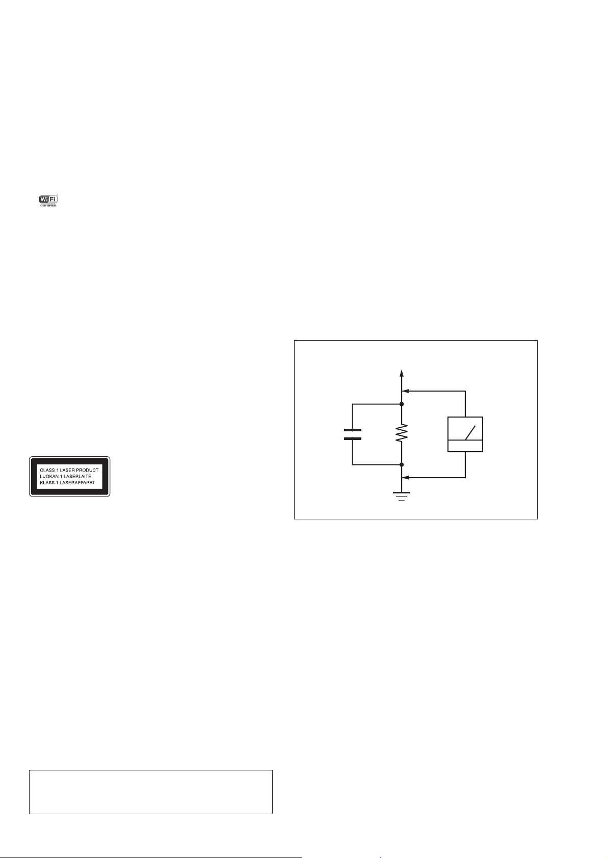
3. Measuring the voltage drop across a resistor by means of a
VOM or battery-operated AC voltmeter. The “limit” indication
is 0.75 V, so analog meters must have an accurate low-voltage
scale. The Simpson 250 and Sanwa SH-63Trd are examples
of a passive VOM that is suitable. Nearly all battery operated
digital multimeters that have a 2 V AC range are suitable. (See
Fig. A)
To Exposed Metal
Parts on Set
AC
1.5 kΩ0.15 μF
voltmeter
(0.75 V)
This appliance is classied as a
CLASS 1 LASER product. This
marking is located on the rear
exterior.
NOTES ON CHIP COMPONENT REPLACEMENT
• Never reuse a disconnected chip component.
• Notice that the minus side of a tantalum capacitor may be damaged by heat.
CAUTION
Use of controls or adjustments or performance of procedures
other than those specifi ed herein may result in hazardous radia-
tion exposure.
Earth Ground
Fig. A. Using an AC voltmeter to check AC leakage.
SAFETY-RELATED COMPONENT WARNING!
COMPONENTS IDENTIFIED BY MARK 0 OR DOTTED LINE
WITH MARK 0 ON THE SCHEMATIC DIAGRAMS AND IN
THE PARTS LIST ARE CRITICAL TO SAFE OPERATION.
REPLACE THESE COMPONENTS WITH SONY PARTS
WHOSE PART NUMBERS APPEAR AS SHOWN IN THIS
MANUAL OR IN SUPPLEMENTS PUBLISHED BY SONY.
ATTENTION AU COMPOSANT AYANT RAPPORT
À LA SÉCURITÉ!
LES COMPOSANTS IDENTIFIÉS PAR UNE MARQUE 0 SUR
LES DIAGRAMMES SCHÉMATIQUES ET LA LISTE DES
PIÈCES SONT CRITIQUES POUR LA SÉCURITÉ DE FONCTIONNEMENT. NE REMPLACER CES COMPOSANTS QUE
PAR DES PIÈCES SONY DONT LES NUMÉROS SONT DONNÉS DANS CE MANUEL OU DANS LES SUPPLÉMENTS
PUBLIÉS PAR SONY.
2

HCD-SBT100/SBT100B/SBT300W/SBT300WB
TABLE OF CONTENTS
1. SERVICING NOTES ............................................. 4
2. DISASSEMBLY
2-1. Disassembly Flow ........................................................... 8
2-2. Case Block ...................................................................... 9
2-3. Plate (CD) Ornament Block ............................................ 9
2-4. Flexible Flat Cable (19P) (FFC6)
(HCD-SBT300W/SBT300WB) ...................................... 10
2-5. Tape (Sub Material) ........................................................ 11
2-6. Panel (Front) Block-1 ..................................................... 12
2-7. Panel (Front) Block-2 ..................................................... 13
2-8. Panel (Back) Block ......................................................... 13
2-9. NET Board Block (HCD-SBT300W/SBT300WB) ........ 14
2-10. WiFi Module (WIFI1), NET Board
(HCD-SBT300W/SBT300WB) ...................................... 14
2-11. 2.4GHz Antenna (ANT1), Holder (Antenna)
(HCD-SBT300W/SBT300WB) ...................................... 15
2-12. Chassis (Main) Block-1 .................................................. 16
2-13. Chassis (Main) Block-2 .................................................. 17
2-14. TUNER Board (HCD-SBT100/SBT300W) ................... 18
2-15. Module (DAB Tuner) (DAB1), DAB Board
(HCD-SBT100B/SBT300WB) ....................................... 18
2-16. MAIN Board ................................................................... 19
2-17. Power Cord (AC1) .......................................................... 19
2-18. POWER Board ................................................................ 20
2-19. CD Mechanism Deck Block ........................................... 21
2-20. FFC Holder ..................................................................... 21
2-21. Optical Pick-up (CMS-S76RFS7G) (OP1) ..................... 22
3. TEST MODE ............................................................ 23
4. ELECTRICAL CHECKS ...................................... 25
5. DIAGRAMS
5-1. Block Diagram - CD Section - ........................................ 27
5-2. Block Diagram - AUDIO Section - ................................. 28
5-3. Block Diagram
- PANEL/POWER SUPPLY Section - ............................ 29
5-4. Schematic Diagram - MAIN Section (1/7) - ................... 31
5-5. Schematic Diagram - MAIN Section (2/7) - ................... 32
5-6. Schematic Diagram - MAIN Section (3/7) - ................... 33
5-7. Schematic Diagram - MAIN Section (4/7) - ................... 34
5-8. Schematic Diagram - MAIN Section (5/7) - ................... 35
5-9. Schematic Diagram - MAIN Section (6/7) - ................... 36
5-10. Schematic Diagram - MAIN Section (7/7) - ................... 37
5-11. Printed Wiring Boards - MAIN Section (1/2) - .............. 38
5-12. Printed Wiring Board - MAIN Section (2/2) - ................ 39
5-13. Printed Wiring Boards - USB/HP/RELAY Boards - ....... 40
5-14. Schematic Diagram - USB/HP/RELAY Boards - ........... 41
5-15. Printed Wiring Board
- NET Board (HCD-SBT300W/SBT300WB) - .............. 42
5-16. Schematic Diagram
- NET Board (HCD-SBT300W/SBT300WB) - .............. 43
5-17. Printed Wiring Board - FL Board - ................................. 44
5-18. Schematic Diagram - FL Board - .................................... 45
5-19. Printed Wiring Boards - KEY/ILLUMI Boards - ........... 46
5-20. Schematic Diagram - KEY/ILLUMI Boards - ............... 47
5-21. Schematic Diagram - POWER Board - .......................... 48
5-22. Printed Wiring Board - POWER Board - ........................ 49
6. EXPLODED VIEWS
6-1. Case Section .................................................................... 65
6-2. Base (CD) Section .......................................................... 66
6-3. FL Board Section ............................................................ 67
6-4. Panel (Front) Section ...................................................... 68
6-5. Panel (Back) Section ....................................................... 69
6-6. MAIN Board Section ...................................................... 70
6-7. Chassis Section ............................................................... 71
6-8. CD Mechanism Deck Section (CDM90-DVBU202) ..... 72
7. ELECTRICAL PARTS LIST .............................. 73
3
HCD-SBT100/SBT100B/SBT300W/SBT300WB
SECTION 1
SERVICING NOTES
NOTES ON HANDLING THE OPTICAL PICK-UP
BLOCK OR BASE UNIT
The laser diode in the optical pick-up block may suffer electrostatic break-down because of the potential difference generated by
the charged electrostatic load, etc. on clothing and the human body.
During repair, pay attention to electrostatic break-down and also
use the procedure in the printed matter which is included in the
repair parts.
The fl exible board is easily damaged and should be handled with
care.
NOTES ON LASER DIODE EMISSION CHECK
The laser beam on this model is concentrated so as to be focused
on the disc refl ective surface by the objective lens in the optical
pickup block. Therefore, when checking the laser diode emission,
observe from more than 30 cm away from the objective lens.
UNLEADED SOLDER
Boards requiring use of unleaded solder are printed with the leadfree mark (LF) indicating the solder contains no lead.
(Caution: Some printed circuit boards may not come printed with
the lead free mark due to their particular size)
: LEAD FREE MARK
Unleaded solder has the following characteristics.
• Unleaded solder melts at a temperature about 40 °C higher
than ordinary solder.
Ordinary soldering irons can be used but the iron tip has to be
applied to the solder joint for a slightly longer time.
Soldering irons using a temperature regulator should be set to
about 350 °C.
Caution: The printed pattern (copper foil) may peel away if
the heated tip is applied for too long, so be careful!
• Strong viscosity
Unleaded solder is more viscous (sticky, less prone to fl ow)
than ordinary solder so use caution not to let solder bridges
occur such as on IC pins, etc.
• Usable with ordinary solder
It is best to use only unleaded solder but unleaded solder may
also be added to ordinary solder.
CHECKING THE OPERATION AFTER REPAIR
After repair completion, connect the “iPod” etc. corresponding to
this unit, and check the operation of playback (HCD-SBT300W/
SBT300WB only), charge, etc.
NOTE OF PERFORMING THE OPERATION CHECK IN
THE STATE THAT HEAT SINK WAS REMOVED
When performing the operation check in the state that this unit was
disassembled, it is possible to perform the operation check in the
state that heat sink was removed. But perform the operation check
in the volume state as low as possible.
TEST DISCS
Use following TEST DISC (for CD) when this unit confi rms the
operation and checks it.
Part No. Description
3-702-101-01 DISC (YEDS-18), TEST
4-225-203-01 DISC (PATD-012), TEST
RELEASING THE DISC TRAY LOCK
The disc tray lock function for the antitheft of sample disc in the
shop is equipped.
Releasing Procedure:
1. Press the [
] button to turn the power on.
?/1
2. Press the [FUNCTION] button to turn the CD function.
3. Press two buttons of the [x] and [Z] simultaneously for fi ve
seconds.
4. The message “UNLOCKED” is displayed on the fl uorescent
indicator tube and the disc tray is unlocked.
Note: When “LOCKED” is displayed, the disc tray lock is not released by
turning power on/off with the [
?/1
] button.
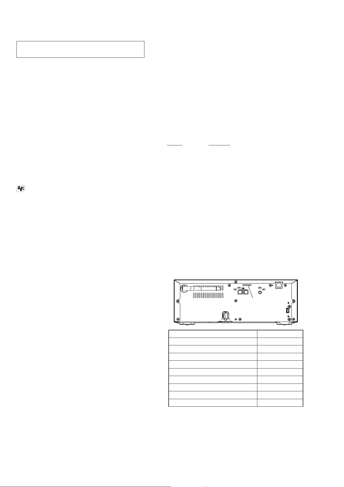
MODEL IDENTIFICATION
Distinguish by Part No. on the rear side of a main unit.
– Rear Panel –
NOTE OF REPLACING THE TUNER BOARD
When the TUNER board is defective, exchange the complete
mounted board.
NOTE OF REPLACING THE DAB BOARD
When the DAB board is defective, exchange the complete mounted board.
NOTE OF REPLACING THE MS-476 BOARD
When the MS-476 board is defective, exchange the CDM90 ASSY
(Ref. No. CDM1).
NOTE OF REPLACING THE IC501, IC502, IC504, IC702,
IC841, IC851, IC902, IC903 AND IC904 ON THE MAIN
BOARD
IC501, IC502, IC504, IC702, IC841, IC851, IC902, IC903 and
IC904 on the MAIN board cannot exchange with single. When
these parts are damaged, exchange the complete mounted board.
NOTE OF REPLACING THE IC5003 ON THE NET BOARD
IC5003 on the NET board cannot exchange with single. When this
part is damaged, exchange the complete mounted board.
NOTE OF REPLACING THE IC5008 ON THE USB BOARD
IC5008 on the USB board cannot exchange with single. When this
part is damaged, exchange the complete mounted board.
Model Part No.
HCD-SBT100: AEP model
HCD-SBT100: US model
HCD-SBT100: Canadian model
HCD-SBT100: Australian model
HCD-SBT100B: AEP and UK models
HCD-SBT300W: AEP model
HCD-SBT300W: Australian model
HCD-SBT300WB: AEP and UK models
HCD-SBT300WB: Australian model
PART No.
4-462-108-0[]
4-462-108-1[]
4-462-108-2[]
4-462-108-3[]
4-462-108-7[]
4-463-724-0[]
4-463-724-1[]
4-463-724-2[]
4-463-724-4[]
4
HCD-SBT100/SBT100B/SBT300W/SBT300WB
CAPACITOR ELECTRICAL DISCHARGE PROCESSING
When checking the board, the electrical discharge is necessary for
the electric shock prevention.
Connect the resistor to both ends of respective capacitors.
• POWER board
C967
– POWER Board (Conductor Side) –
NOTE OF REPLACING THE WiFi MODULE (Ref. No.
WIFI1) (HCD-SBT300W/SBT300WB only)
When replacing the WiFi module (Ref. No. WIFI1), MAC address
is changed. Print the following explanation, cut it, and hand over
it to the customer with the unit, when returning the unit that the
repair is completed to the customer.
MAC address of this unit has been changed by this repair. The
customer who uses the MAC address fi ltering function of con-
nected access point equipment please set it again. MAC address
is possible to confi rm it on the Sony Network Device Setting
screen. Please refer to “Network connections” on the operating
instructions for details.
CHECKING METHOD OF NETWORK CONNECTION
(HCD-SBT300W/SBT300WB only)
It is necessary to check the network connection, when replacing
the complete MAIN board, complete NET board, IC101 on the
MAIN board or WiFi module (Ref. No. WIFI1). Check the connection of wireless and wired LAN, according to the following
method.
1. Checking Method of Wireless LAN Connection
Necessary Equipment:
• Access point supporting WPS
800 Ω/2 W
C967
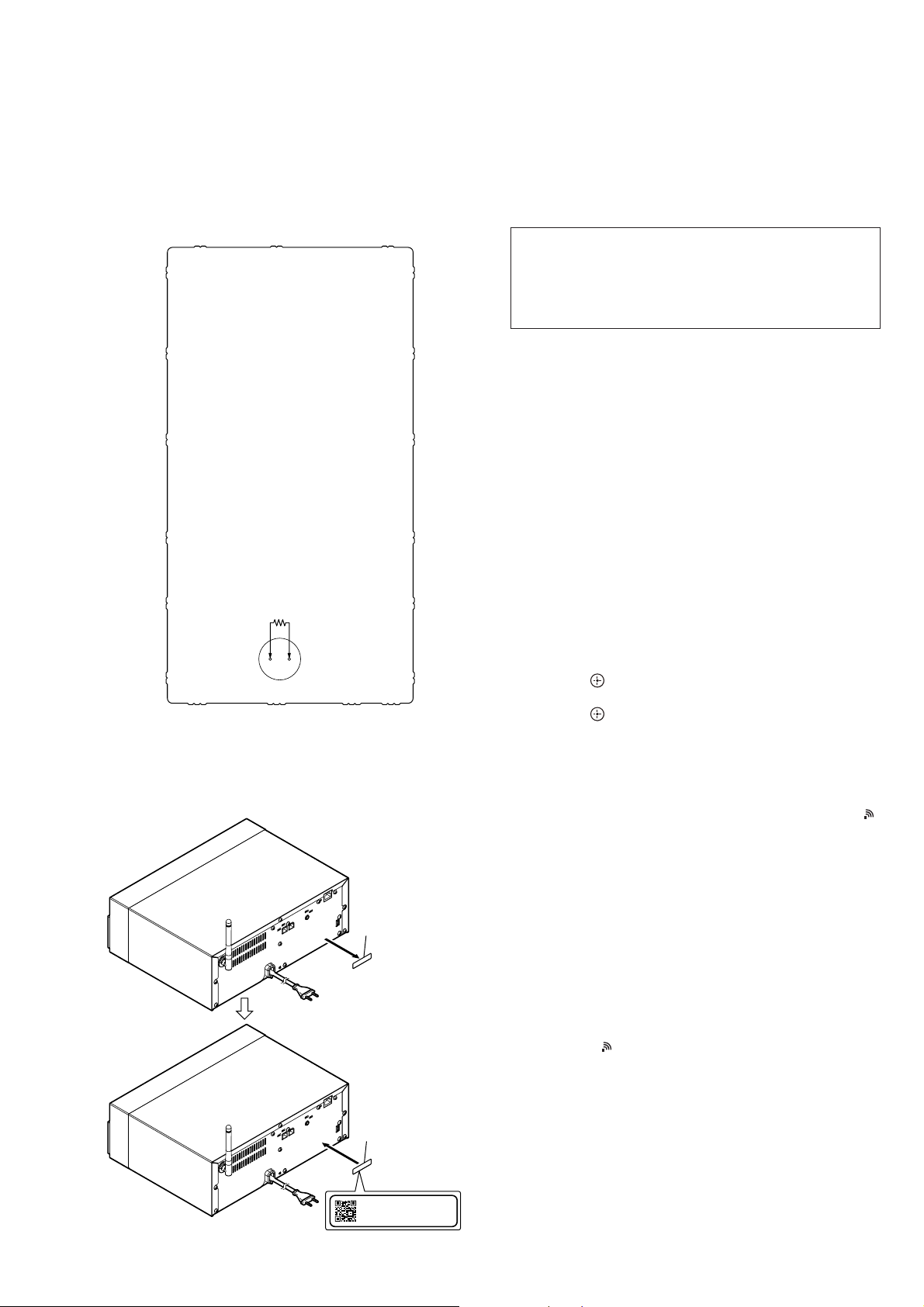
PROCESSING OF REPLACING THE WiFi MODULE
(Ref. No. WIFI1) (HCD-SBT300W/SBT300WB only)
When replacing the WiFi module (Ref. No. WIFI1), peel the device ID label stuck on the rear side of a main unit, and stick on the
new device ID label (refer to the following fi gure) enclosed with
the new WiFi module (Ref. No. WIFI1)
1 Peel the device
ID label.
Procedure:
1. Press the [
] button to turn the power on.
?/1
2. Press the [OPTIONS] button on the remote commander to the
display the setting menu on the fl uorescent indicator tube.
3. Press the [V]/[v] buttons on the remote commander to select
“WPS”.
4. Press the [ ] button on the remote commander.
(“OK” fl ashes on the fl uorescent indicator tube)
5. Press the [ ] button on the remote commander.
(“WPS” fl ashes on the fl uorescent indicator tube)
6. Press the [WPS] button on the access point.
7. When wireless LAN connection is started, “CONNECT”
fl ashes on the fl uorescent indicator tube.
8. When wireless LAN connection is completed, “COMPLETE”
appears for a moment on the fl uorescent indicator tube, then “
”
appears on the fl uorescent indicator tube.
9. Press the [
Note: Refer to the instruction manual about details of the setting method.
] button to turn the power off.
?/1
2. Checking method of wired LAN connection
Necessary Equipment:
• Router
• Network (LAN) cable
Procedure:
1. Connect the main unit to the router with the LAN cable.
2. Press the [
] button to turn the power on.
?/1
3. Check that “ ” appears on the fl uorescent indicator tube.
4. Press the [
Note: Refer to the instruction manual about details of the setting method.
] button to turn the power off.
?/1
– Rear view –
2 Stick on the new
device ID label.
Device ID: XXXXXXXXXXXXX
MAC Address: XX-XX-XX-XX-XX-XX
5
HCD-SBT100/SBT100B/SBT300W/SBT300WB
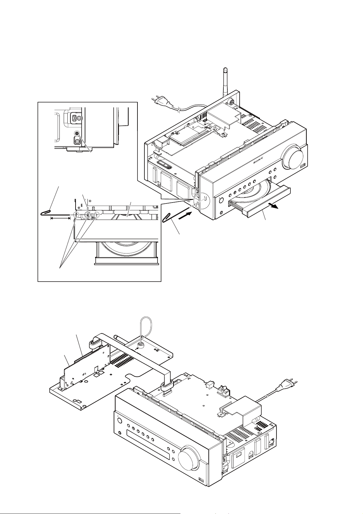
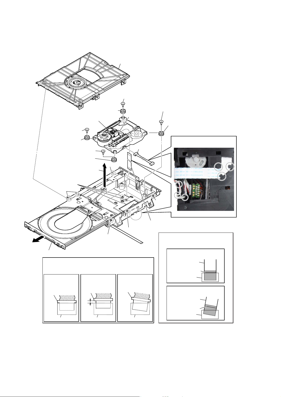
HOW TO OPEN THE TRAY WHEN POWER SWITCH TURN OFF
Note 1: After the case is removed, this work is done.
Note 2: Please prepare the thin wire (clip etc. processed to the length of 8 cm or more).
hole
– Side view –
Insert the clip etc. processed to the
length of 8 cm or more in the hole
on the side of the chassis and push.
HP board
CD mechanism deck
8 cm or more
tray
Push after it inserts it
Note:
in these three holes well.
– Top view –
NET BOARD, WiFi MODULE SERVICE POSITION
WiFi module (WIFI1)
NET board
2 Draw out the tray.
1 Insert the clip etc. in the hole
of the chassis, and push the
lever in the direction of the
arrow.
6
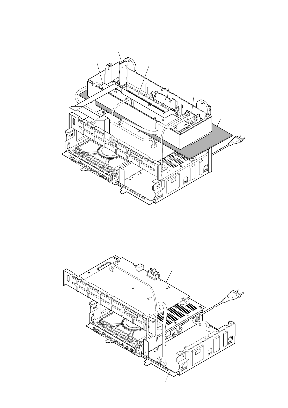
FL, HP, KEY BOARDS SERVICE POSITION
HP board
HCD-SBT100/SBT100B/SBT300W/SBT300WB
FL board
KEY board
ILLUMI board
USB board
insulating sheet
MAIN, POWER BOARDS SERVICE POSITION
MAIN board
POWER board
7
HCD-SBT100/SBT100B/SBT300W/SBT300WB
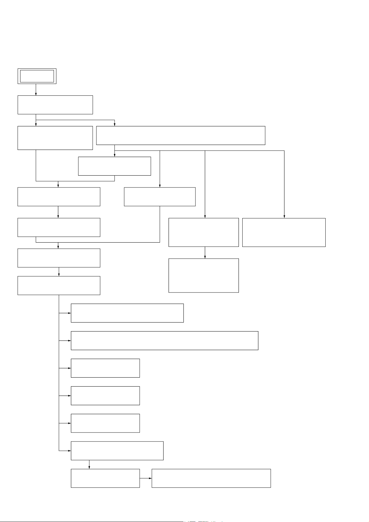
SECTION 2
DISASSEMBLY
• This set can be disassembled in the order shown below.
2-1. DISASSEMBLY FLOW
SET
2-2. CASE BLOCK
(Page 9)
2-3. PLATE (CD) ORNAMENT
BLOCK
(Page 9)
2-5. TAPE (SUB MATERIAL)
(Page 11)
2-6. PANEL (FRONT) BLOCK-1
(Page 12)
2-7. PANEL (FRONT) BLOCK-2
(Page 13)
2-12. CHASSIS (MAIN) BLOCK-1
(Page 16)
2-13. CHASSIS (MAIN) BLOCK-2
(Page 17)
2-14. TUNER BOARD (HCD-SBT100/SBT300W)
(Page 18)
2-4. FLEXIBLE FLAT CABLE (19P) (FFC6) (HCD-SBT300W/SBT300WB)
(Page 10)
2-8. PANEL (BACK) BLOCK
(Page 13)
2-9. NET BOARD BLOCK
(HCD-SBT300W/
SBT300WB)
(Page 14)
2-10. WiFi MODULE (WIFI1),
NET BOARD
(HCD-SBT300W/
SBT300WB)
(Page 14)
2-11. 2.4GHz ANTENNA (ANT1),
HOLDER (ANTENNA)
(HCD-SBT300W/SBT300WB)
(Page 15)
2-15. MODULE (DAB TUNER) (DAB1), DAB BOARD (HCD-SBT100B/SBT300WB)
(Page 18)
2-16. MAIN BOARD
(Page 19)
2-17. POWER CORD (AC1)
(Page 19)
2-18. POWER BOARD
(Page 20)
2-19. CD MECHANISM DECK BLOCK
(Page 21)
2-20. FFC HOLDER
(Page 21)
2-21. OPTICAL PICK-UP (CMS-S76RFS7G) (OP1)
(Page 22)
8
Note: Follow the disassembly procedure in the numerical order given.
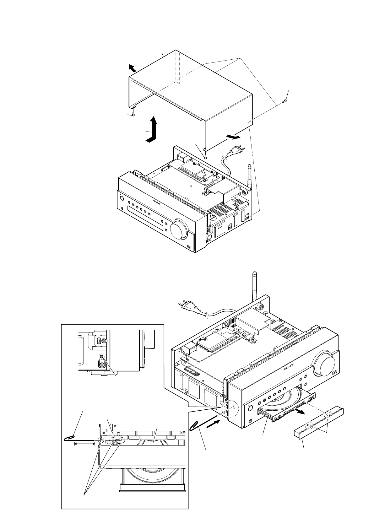
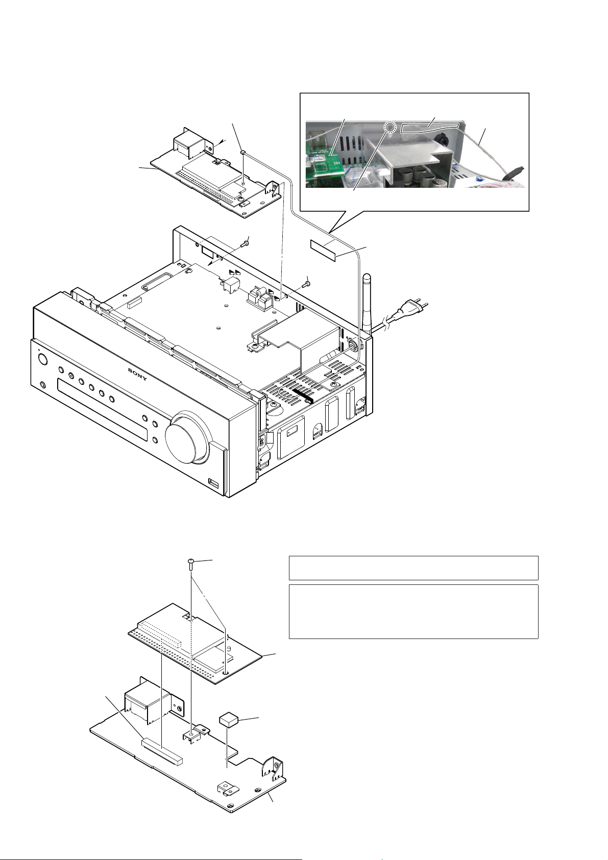
2-2. CASE BLOCK
4 case block
2
1 screw (BVTP S3 u 6)
HCD-SBT100/SBT100B/SBT300W/SBT300WB
1 three screws
(BVTP S3 u 6)
3 Remove the case block in the
direction of an arrow.
2-3. PLATE (CD) ORNAMENT BLOCK
1 screw
(BVTP S3 u 6)
2
hole
– Side view –
Insert the clip etc. processed to the
length of 8 cm or more in the hole
on the side of the chassis and push.
HP board
8 cm or more
Push after it inserts it
Note:
in these three holes well.
CD mechanism deck
tray
– Top view –
2 Draw out the tray.
1 Insert the clip etc. in the hole
of the chassis, and push the
lever in the direction of the
arrow.
3 two claws
4 plate (CD) ornament
block
9
HCD-SBT100/SBT100B/SBT300W/SBT300WB
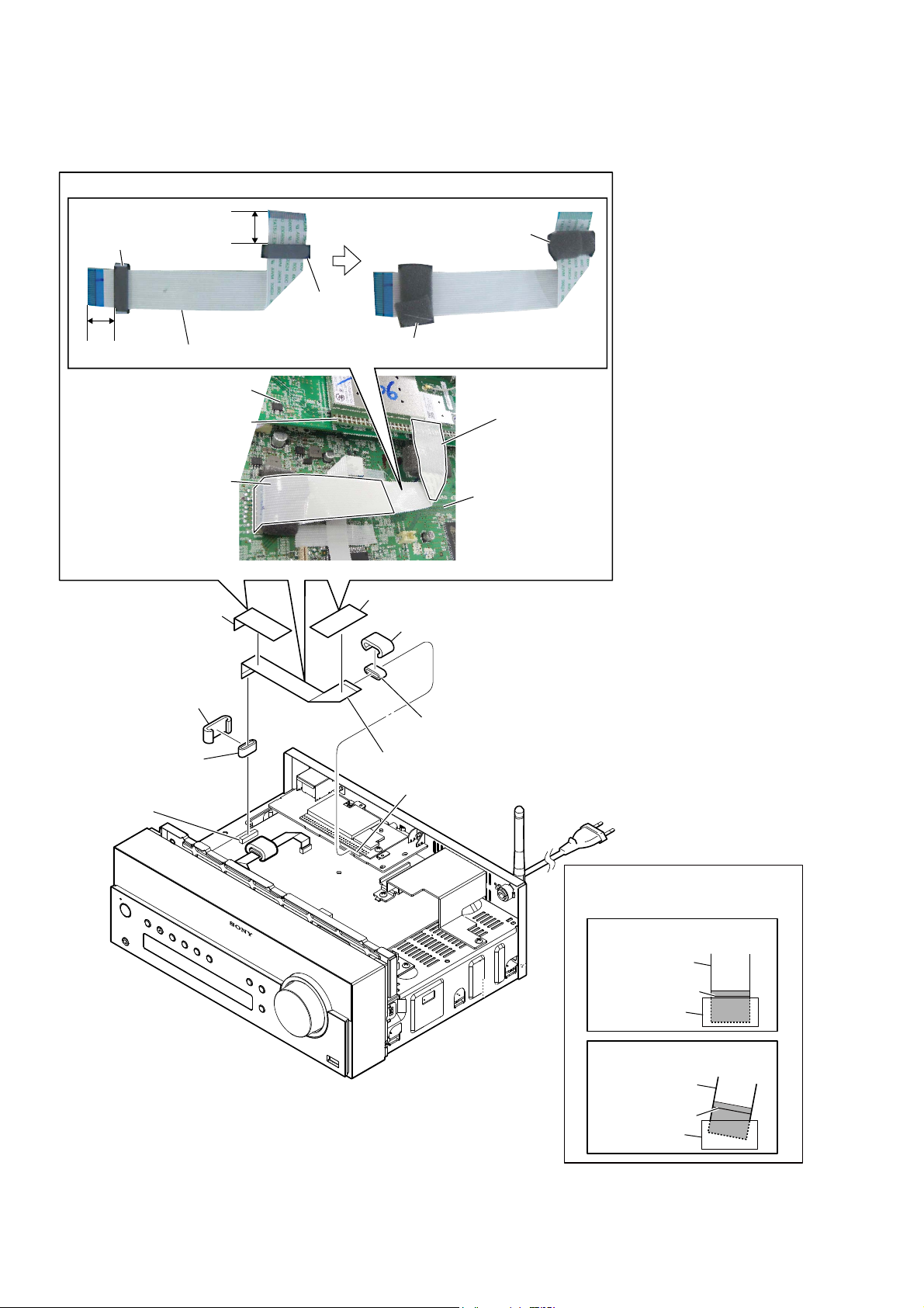
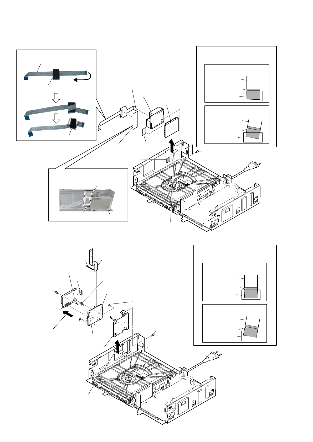
2-4. FLEXIBLE FLAT CABLE (19P) (FFC6) (HCD-SBT300W/SBT300WB)
)OH[LEOHIODWFDEOH3))&VHWWLQJ
ferrite core (FC3)
15 to 20 mm
1 tape
(sub material)
15 to 20 mm
ferrite
core
(FC4)
flexible flat cable (19P) (FFC6)
NET board
WiFi module
tape
(sub material)
cushion (S)
1 tape
(sub material)
cushion (S)
4
cushion (S)
tape
(sub material)
MAIN board
4
5 ferrite core
(FC3)
3 connector
(CN408)
cushion (S)
6 ferrite core
flexible flat cable (19P) (FFC6)
7
2 connector
(CN5010)
(FC4)
When installing the flexible flat cable,
Note:
ensure the colored line.
No slanting after insertion.
Inserting is straight to the interior.
flexible flat cable
flexible flat cable
colored line
OK
colored line
connector
NG
Inserting is slant.
connector
10
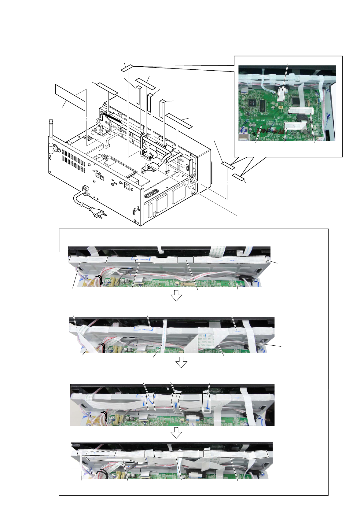
2-5. TAPE (SUB MATERIAL)
1 tape
(sub material)
HCD-SBT100/SBT100B/SBT300W/SBT300WB
:LUHVHWWLQJ
tape (sub material)
5 tape
(sub material)
6 tape
(sub material)
:LUHVHWWLQJ
1 Check that three tapes are pasted to the chassis (main).
3 tape
(sub material)
4 tape
(sub material)
3 tape
(sub material)
3 tape
(sub material)
–5HDUYLHZ–
2 tape
(sub material)
1 tape
(sub material)
MAIN board
1 tape
(sub material)
tape
(sub material)
tape
(sub material)
tape (sub material)tape (sub material)
2 Place the cable of each on top of tapes (sub material).
tape (sub material)
flexible flat cable (9P)
3 Paste three tapes (sub material).
tape (sub material)
4 Paste five tapes (sub material).
tape (sub material) tape (sub material)
flexible flat cable (8P)
tape (sub material) tape (sub material)
chassis (main)
MAIN board
flexible flat cable (17P)
tape
(sub material)
flexible flat cable
(14P)
tape
(sub material)
tape
(sub material)
tape
(sub material)
tape
(sub material)
11
HCD-SBT100/SBT100B/SBT300W/SBT300WB
2-6. PANEL (FRONT) BLOCK-1
86&DQDGLDQ
)OH[LEOHIODWFDEOH3VHWWLQJ
coating clip
flexible flat cable (9P) MAIN board
7 Remove the flexible flat cable (9P)
from the coating clip.
6 connector
(CN906)
5 connector
(CN3001)
Note 1:
Do not insert to the wrong connector absolutely.
There is a possibility that the unit may be damaged if the wrong.
CN106 and CN340 are quantity of pins of the same.
)HUULWHFRUH)&VHWWLQJ
cushion (S)
ferrite core
(FC1)
20 to 25 mm
1 flexible flat cable (8P)
(CN404)
4 flexible flat cable (17P)
(CN506)
2 flexible flat cable (14P)
(CN407)
3 flexible flat cable (9P)
(CN340)
When you install the connector, please install them correctly.
Note 2:
There is a possibility that this machine damages when not
correctly installing it.
Insert is straight
to the interior.
connector
CN106
–5HDUYLHZ–
NGOK NG
Insert is shallow
connector
Insert is incline
connector
)HUULWHFRUH)&VHWWLQJ
When installing the flexible flat cable,
Note 3:
ensure the colored line.
No slanting after insertion.
Inserting is straight to the interior.
flexible flat cable
flexible flat cable
OK
colored line
connector
NG
Inserting is slant.
cushion (S)
ferrite core
(FC2)
15 to 20 mm
12
connector
colored line
connector
connector connector
2-7. PANEL (FRONT) BLOCK-2
2 two screws
(BV3)
4 Draw out the wire.
1 screw
(BVTP S3 u 6)
HCD-SBT100/SBT100B/SBT300W/SBT300WB
:LUHVHWWLQJ
5 panel (front) block
Arrange the wire so as not to overlap
Note:
with the screw hole of HP board.
1 screw
(BVTP S3 u 6)
– Rear view –
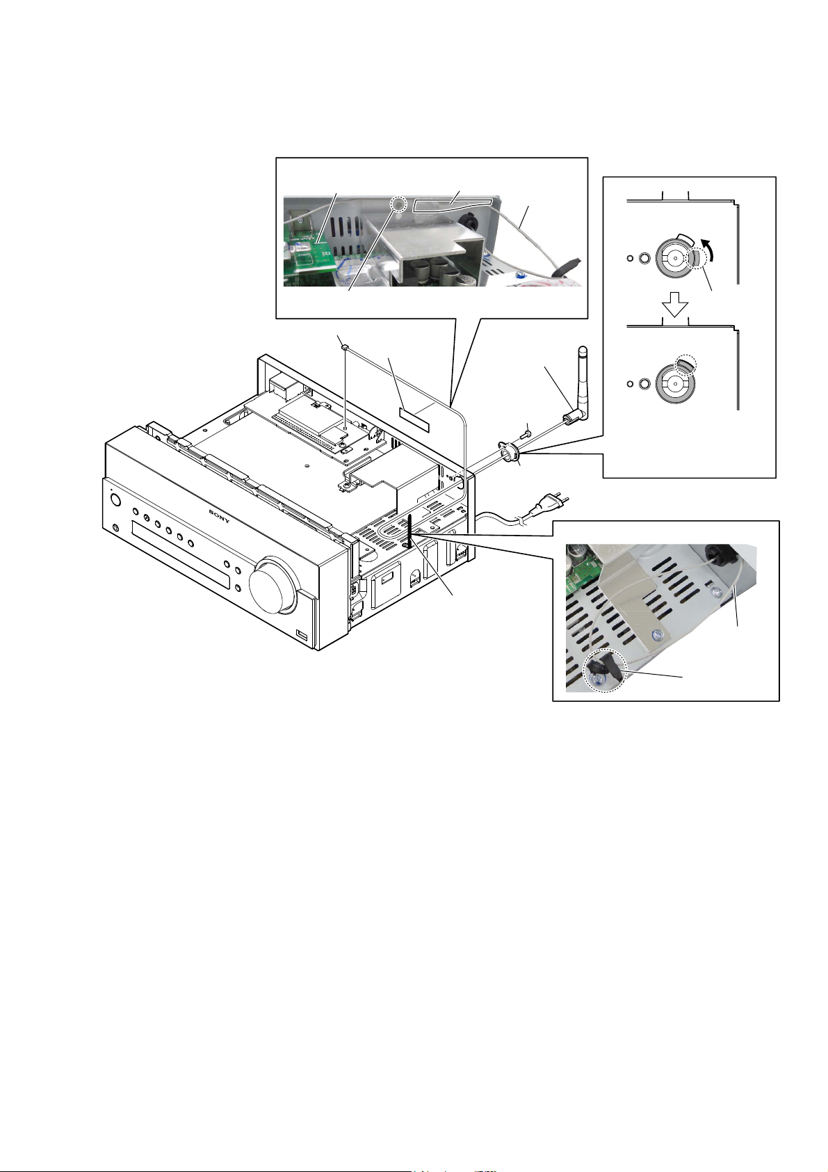
2-8. PANEL (BACK) BLOCK
6%7:6%7:%
:LUHVHWWLQJ
coating clip
antenna wire
4 Draw out
the wire.
3 Remove the panel (front) block
in the direction of an arrow.
1 Remove the antenna wire
from the coating clip.
1 screw
(BVTP S3 u 6)
2 two screws (BV3)
– Left view –
2 three screws
(BVTP3 u 8)
–5HDUYLHZ–
3 panel (back) block
2 two screws
(BVTP3 u 8)
13
HCD-SBT100/SBT100B/SBT300W/SBT300WB
2-9. NET BOARD BLOCK (HCD-SBT300W/SBT300WB)
5 NET board block
1 antenna connector
(CON2)
A
3 two screws
(BVTT3 u 6)
A
:LUHVHWWLQJ
NET board
Note:
with the screw hole of panel (rear).
4 screw
(BVTP3 u 8)
tape
(sub material)
antenna wire
Arrange the antenna wire so as not to overlap
2 tape
(sub material)
2-10. WiFi MODULE (WIFI1), NET BOARD (HCD-SBT300W/SBT300WB)
1 two screws
(BVTT3 u 6)
2 connector
(CN5002)
4 cushion
(poron T5.5)
Note 1: When the complete NET board is replaced, refer to “CHECK-
ING METHOD OF NETWORK CONNECTION” on page 5.
Note 2: When the WiFi module (Ref. No. WIFI1) is replaced, refer to
“PROCESSING OF REPLACING THE WiFi MODULE (Ref.
No. WIFI1)”, “NOTE OF REPLACING THE WiFi MODULE
(Ref. No. WIFI1)” and “CHECKING METHOD OF NETWORK CONNECTION” on page 5.
3 WiFi module (WIFI1)
5 NET board
14
HCD-SBT100/SBT100B/SBT300W/SBT300WB
2-11. 2.4GHz ANTENNA (ANT1), HOLDER (ANTENNA) (HCD-SBT300W/SBT300WB)
:LUHVHWWLQJ
NET board
Arrange the antenna wire so as not to overlap
Note:
with the screw hole of panel (rear).
1 antenna connector
(CON2)
2 tape
(sub material)
tape
(sub material)
4 2.4GHz antenna
(ANT1)
5 screw
(BVTP3 u 8)
7 holder
(antenna)
antenna wire
claw
6 Rotate the claw of holder
(antenna) in the direction of
an arrow, align the hole of
panel (rear).
:LUHVHWWLQJ
3 Remove the antenna
wire from the
coating clip.
antenna wire
coating clip
15
HCD-SBT100/SBT100B/SBT300W/SBT300WB
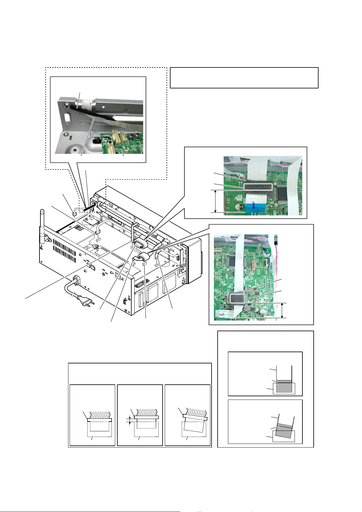
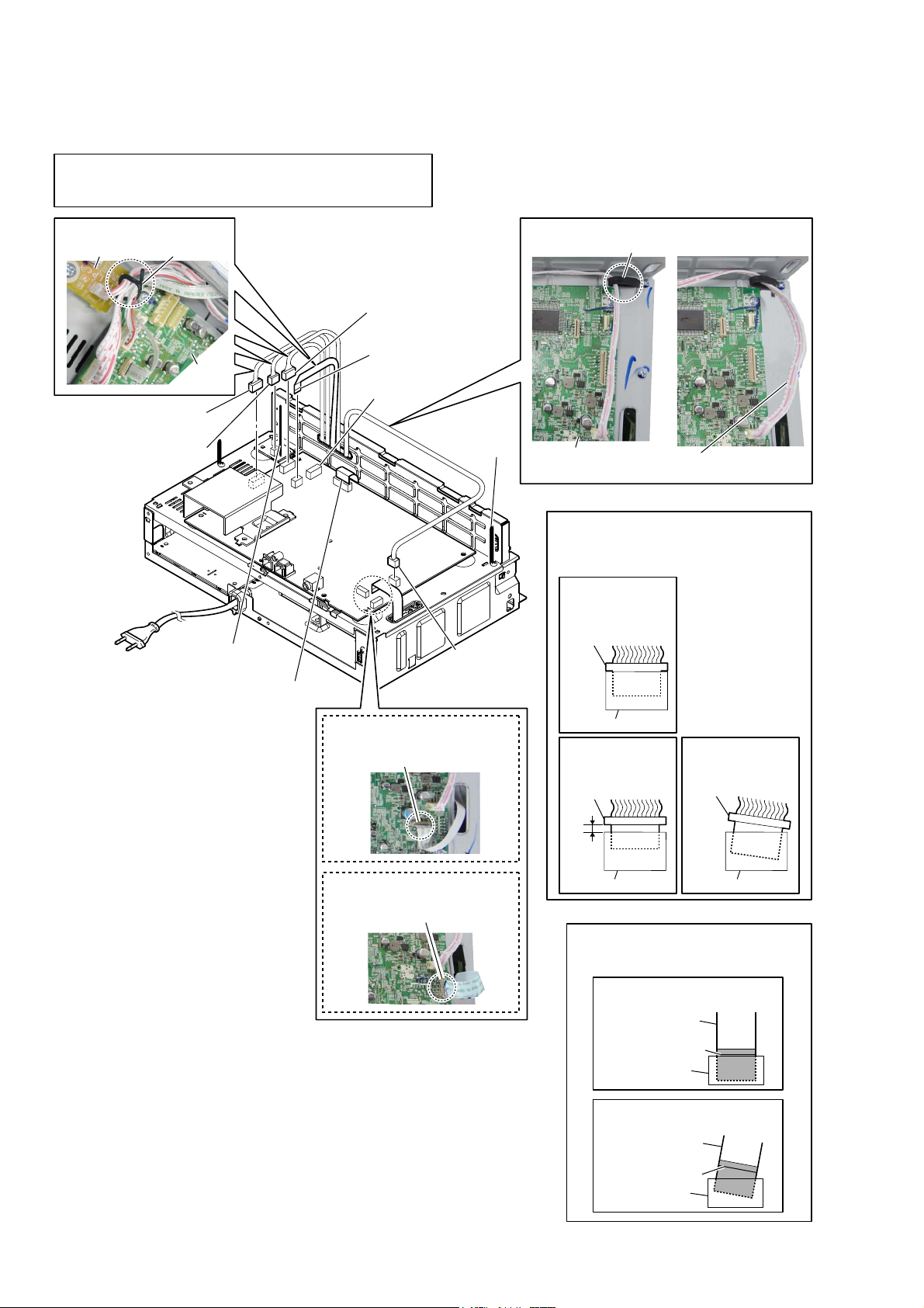
2-12. CHASSIS (MAIN) BLOCK-1
CN3002 and CN507 are quantity of pins of the same.
Note 1:
Do not insert to the wrong connector absolutely.
There is a possibility that the unit may be damaged if the wrong.
WireVeWWiQJ
RELAY board
–5eDrYieZ–
Do not remove this connector (CN501)
Note 2:
at this point.
It is necessary to process electrostatic
measures of optical pick-up.
lead pin
MAIN
board
4 connector
(CN3002)
5 connector
(CN905)
1 Remove wires from
the lead pin.
3 connector
(CN831)
2 flexible flat cable (5P)
(CN502)
CN507
6 Remove the
wire from the
coating clip.
(SBT100/SBT300W)
8 flexible flat cable (9P)
(CN251)
7 connector
(CN304)
WireVeWWiQJ
MAIN board
Note 4:
install them correctly.
There is a possibility that this machine
damages when not correctly installing it.
Insert is straight
to the interior.
connector
Insert is shallow
connector
coating clip
OK
Wire must not be extends
Note 3:
from the edge of the chassis.
When you install the connector, please
OK
connector
NG
NG
NG
Insert is incline
connector
16
(SBT100B/SBT300WB)
8 flexible flat cable (9P)
(CN104)
connector connector
When installing the flexible flat cable,
Note 5:
ensure the colored line.
No slanting after insertion.
Inserting is straight to the interior.
flexible flat cable
flexible flat cable
colored line
OK
colored line
connector
NG
Inserting is slant.
connector
HCD-SBT100/SBT100B/SBT300W/SBT300WB
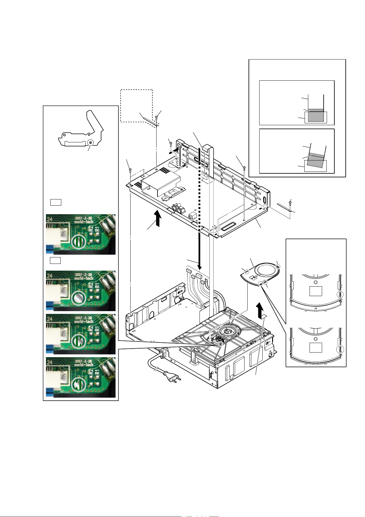
2-13. CHASSIS (MAIN) BLOCK-2
Note 1: Before disconnecting flexible flat cable (24P) (CN501), solder the short-land.
(SBT300W/
SBT300WB)
2 screw
(BV3)
2 screw
(BV3)
9 flexible flat cable (24P)
(CN501)
Solder the short-land.
8
Note 2: When assembling the
chassis (main) block,
remove the solder of
short-land after connecting
flexible flat cable (24P)
(CN501).
OK
Solder is removed cleanly.
3 coating
clip
2 two screw
(BV3)
2 two screws
(BV3)
When installing the flexible flat cable,
Note 3:
ensure the colored line.
No slanting after insertion.
Inserting is straight to the interior.
flexible flat cable
flexible flat cable
OK
colored line
connector
NG
Inserting is slant.
colored line
connector
2 screw
(BV3)
3 coating clip
NG
Solder is not removed.
4 Remove the
chassis (main) block
in the direction
of an arrow.
1 Draw out
wires.
– Rear view –
7 chuck cap
6 claw
0 chassis (main) block
Note 4:
the chuck cap,
6 claw
6 claw
5 Remove the chuck cap
in the direction
of an arrow.
align the triangle
marks.
When installing
OK
NG
17
HCD-SBT100/SBT100B/SBT300W/SBT300WB
2-14. TUNER BOARD (HCD-SBT100/SBT300W)
)OH[LEOHIODWFDEOH3))&VHWWLQJ
flexible flat cable (9P) (FFC3)
5 flexible flat cable (9P)
ferrite core (FC5)
cushion
(CN101)
1 tape
(sub material)
2 Peeled from the
adhesive (BT).
8 TUNER board
7 sheet (tuner)
6 shield (lower)
When installing the flexible flat cable,
Note:
ensure the colored line.
No slanting after insertion.
Inserting is straight to the interior.
flexible flat cable
flexible flat cable
3 two screws
(BVTP3 u 8)
OK
colored line
connector
NG
Inserting is slant.
colored line
connector
:LUHVHWWLQJ
tape
(sub material)
ferrite core (FC5)
TUNER board
4 Remove the TUNER board block
in the direction of an arrow.
2-15. MODULE (DAB TUNER) (DAB1), DAB BOARD (HCD-SBT100B/SBT300WB)
When installing the flexible flat cable,
Note 2:
ensure the colored line.
No slanting after insertion.
Inserting is straight to the interior.
flexible flat cable
flexible flat cable
9 Remove the two solders.
4 screw
(BVTP3 u 8)
qa module
(DAB tuner)
(DAB1)
7 Remove the module
(DAB tuner) block
in the direction
of an arrow.
conductor side
8 gasket
B
qs two screws
(BVTP3 u 8)
5 connector
(CN4001)
qd bracket DAB
flexible flat cable (9P) (CN4004)
3
Note 1:
do not mistake the insertion direction.
qf DAB
board
When installing the flexible flat cable (9P),
0 pin header 2P
(CN01)
6 connector
(CN4003)
qs screw
(BVTP3 u 8)
B
1 two screws
(BVTP3 u 8)
OK
colored line
connector
NG
Inserting is slant.
colored line
connector
18
2 Remove the DAB board
block in the direction
of an arrow.
2-16. MAIN BOARD
2 heatsink
(AMP)
4 screw
(BVTP3 u 8)
1 two screws
(BVTP3 u 8)
4 screw
(BVTP3 u 8)
4 five screws
(BVTP3 u 8)
3 radiation sheet
6 tape
(sub material)
4 screw
(BVTP3 u 8)
HCD-SBT100/SBT100B/SBT300W/SBT300WB
Tape VXE materiaO VettiQJ
7 MAIN board
tape
(sub material)
MAIN board
– Top view –– Bottom view –
ditch
ditch
MAIN board
tape
(sub material)
– Rear view –
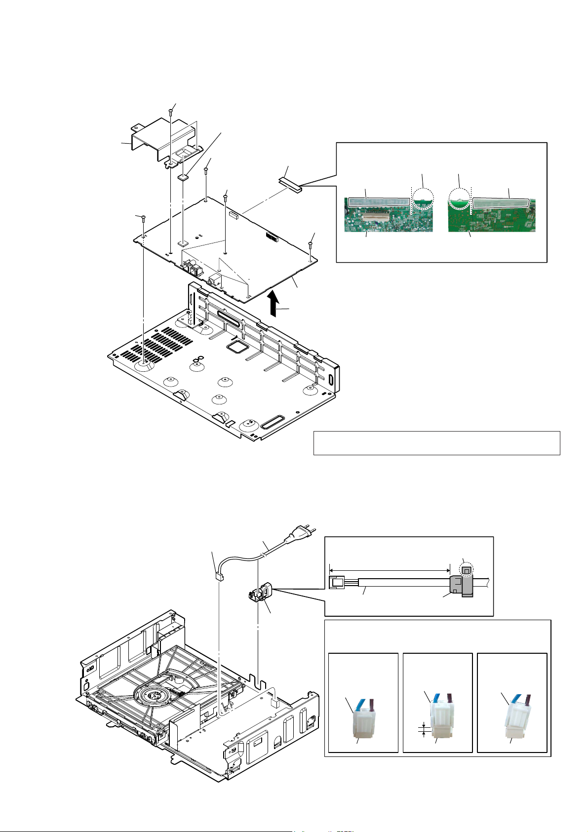
2-17. POWER CORD (AC1)
1 power cord connector
(CN901)
5 Remove the MAIN board block
in the direction of an arrow.
Note: When the complete MAIN board is replaced, refer to “CHECKING
METHOD OF NETWORK CONNECTION” on page 5.
3 power cord
(AC1)
&RUGEXVKVHWWLQJ
claw
70 to 75 mm
2 cord bush
(2104)
power cord
When you install the connector, please install them correctly.
Note:
There is a possibility that this machine damages when not
correctly installing it.
Insert is straight
to the interior.
connector
connector
cord bush
(2104)
NGOK NG
Insert is shallow
connector
connector
Insert is incline
connector
connector
19
HCD-SBT100/SBT100B/SBT300W/SBT300WB
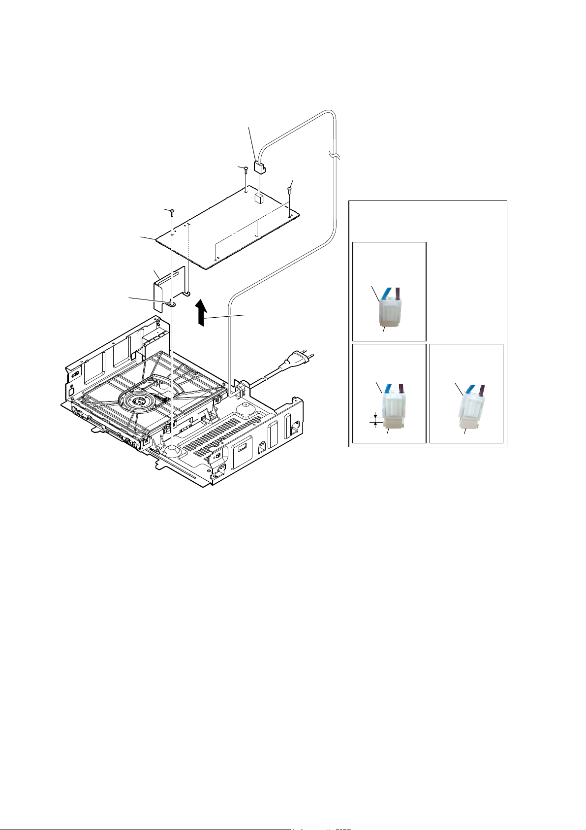
2-18. POWER BOARD
1 power cord connector
(CN901)
2 screw
(BV3)
2 three screws
(BV3)
2 screw
(BV3)
6 POWER board
5 sheet (PS UL) (US, Canadian)/
sheet (PS) (AEP, UK, Australian)
4 Peel off the
adhesive sheet.
3 Remove the
POWER board block
in the direction of
an arrow.
When you install the connector, please
Note:
install them correctly.
There is a possibility that this machine
damages when not correctly installing it.
OK
Insert is straight
to the interior.
connector
connector
NG
Insert is shallow
connector
connector
NG
Insert is incline
connector
connector
20
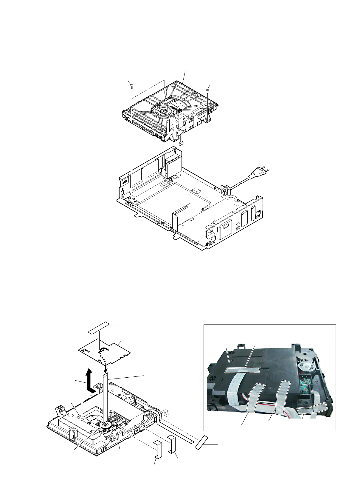
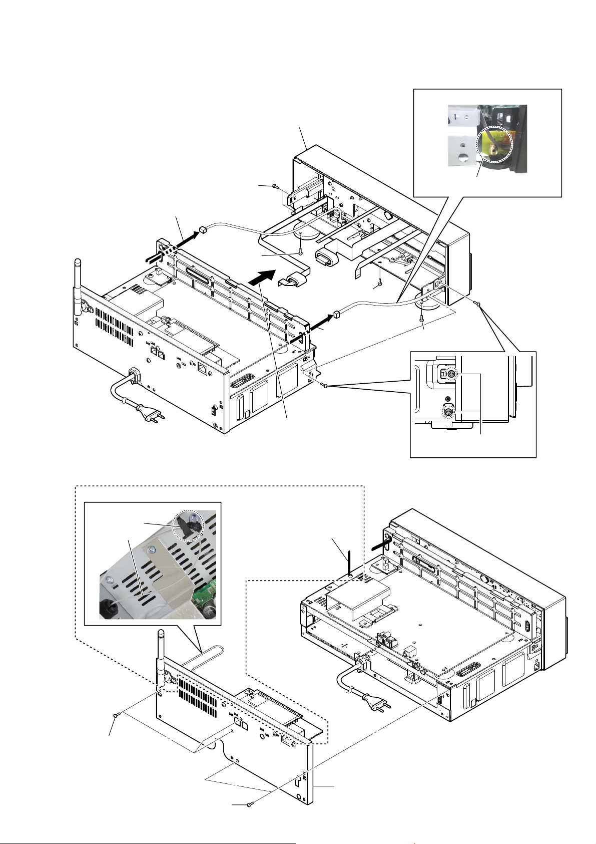
2-19. CD MECHANISM DECK BLOCK
HCD-SBT100/SBT100B/SBT300W/SBT300WB
1 two screws
(BV3)
2 CD mechanism deck block
1 two screws
(BV3)
2-20. FFC HOLDER
1 tape
(sub material)
4
Note:
check that installed firmly
two bosses and claw.
2 Remove the
FFC holder
in the direction
of an arrow.
boss
boss
–&'PHFKDQLVPGHFNEORFNERWWRPYLHZ–
claw
FFC holder
When installing the FFC holder,
3 Draw out the
flexible flat
cable (24P).
1 tape
(sub material)
:LUHVHWWLQJ
FFC holder
1 tape
(sub material)
tape
(sub material)
1 tape
(sub material)
tape
(sub material)
tape
(sub material)
tape
(sub material)
21
HCD-SBT100/SBT100B/SBT300W/SBT300WB
2-21. OPTICAL PICK-UP (CMS-S76RFS7G) (OP1)
chuck holder block
2
5 insulator
screw
5 insulator
screw
0 insulator
5 insulator screw
Remove the
6
in the direction of an arrow.
3 Draw out the tray.
Note 1:
There is a possibility that this machine damages when not
correctly installing it.
Insert is straight
to the interior.
connector
optical pick-up
three
4
claws
two
1
claws
When you install the connector, please install them correctly.
qa optical pick-up
(CMS-S76RFS7G)
(OP1)
0 insulator
connector
0 insulator
block
claw
1
NGOK NG
Insert is shallow
1
claw
connector
7 connector
9 connector
claw
1
Insert is incline
5 insulator screw
0 insulator
WireVHWWLQJ
claw
1
–BRWWRPYLHZ–
8 flexible flat cable (24P)
(FFC1)
When installing the flexible flat cable,
Note 2:
ensure the colored line.
No slanting after insertion.
Inserting is straight to the interior.
flexible flat cable
flexible flat cable
OK
colored line
connector
NG
Inserting is slant.
22
connector
colored line
connector
connector connector
HCD-SBT100/SBT100B/SBT300W/SBT300WB
SECTION 3
TEST MODE
COLD RESET
It can clears all data including preset data stored in the memory to
initial conditions. Execute this mode when returning the this unit
to the customer.
Procedure:
1. Press the [?/1] button to turn the power on.
2. Press two buttons of the [x] and [?/1] simultaneously for three
seconds.
3. The message “RESET” (HCD-SBT100/SBT100B) or “ALL
RESET” (HCD-SBT300W/SBT300WB) is displayed on the
fl uorescent indicator tube, then becomes the standby state.
AUTO STANDBY TEST
It can confi rm the auto standby function operates normally.
The auto standby function operates in 60 seconds in this mode.
(Usually, it takes 30 minutes)
Procedure:
1. Press the [?/1] button to turn the power on.
2. Press the [FUNCTION] button to turn except “FM”, “AM”
and “DAB”.
3. Press two buttons of the [BASS BOOST] and [FUNCTION]
simultaneously for three seconds.
4. It enters the auto standby test mode, and the following screen
is displayed on the fl uorescent indicator tube.
(In this mode, “STEREO” continues blinking on the fl uores-
cent indicator tube)
Screen display
STEREO
COMMON TEST
It can confi rm the MAX/MIN of volume.
Procedure:
1. Press the [?/1] button to turn the power on.
2. Press two buttons of the [BASS BOOST] and [u] simultane-
ously for three seconds.
3. It enters the common test mode, the message “AUDIO IN” is
displayed on the fl uorescent indicator tube.
(In this mode, “cPLAY” and “SLEEP” continues blinking on
the liquid crystal display)
4. When rotating the [VOLUME] knob, the message is changed
with VOLUME MIN ↔ VOLUME 23 ↔ VOLUME MAX on
the fl uorescent indicator tube.
Releasing method:
Press the [?/1] button to turn the power off.
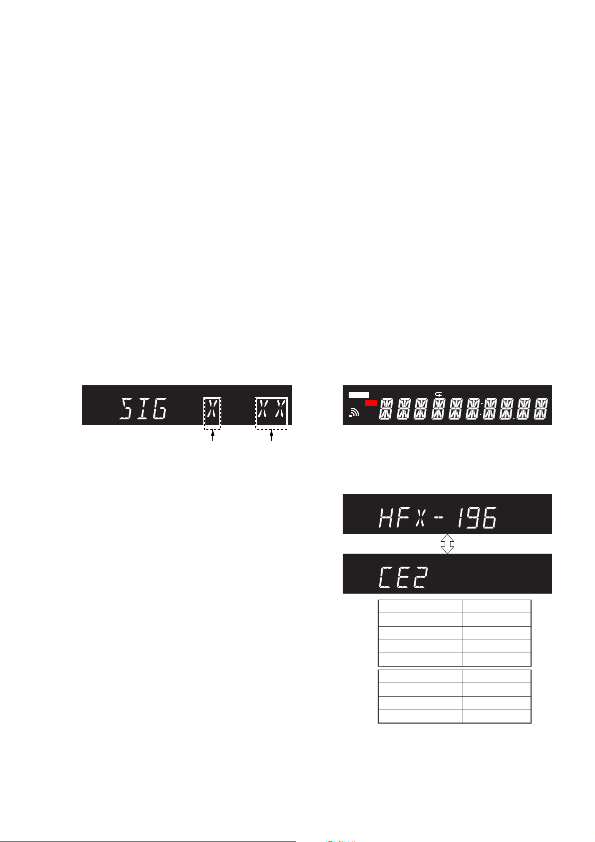
PANEL TEST
It can confi rm the fl uorescent indicator tube, LEDs, model name,
destination, software version and button.
Procedure:
1. Press the [?/1] button to turn the power on.
2. Press two buttons of the [FUNCTION] and [. TUNE −]
simultaneously for three seconds.
3. It enters the panel test mode, and all segments on the fl uores-
cent indicator tube and all LEDs light up.
Screen display
UPDATE
NX
FLDR SHUF PGM
REC
1
cPLAY cREC
SLEEPSTEREO
Signal level
(0 or 1)
Countdown
timer
(60 to 0)
5. In the case of the following states, the countdown timer decreases. This unit will become standby states if the countdown
timer decreases to “0”.
• Operation is not performed.
• The signal level is lower than threshold.
Releasing method:
Press two buttons of the [BASS BOOST] and [FUNCTION] simultaneously for three seconds.
4. When pressing the [> TUNE +] button, the model name and
destination are displayed on the fl uorescent indicator tube al-
ternately.
(In this mode, “STEREO” continues blinking on the fl uores-
cent indicator tube)
Screen display
STEREO
STEREO
Model Name
HCD-SBT100
HCD-SBT100B
HCD-SBT300W
HCD-SBT300WB
Destination Display
US and Canadian
AEP and UK
Australian
Display
HFX-193
HFX-194
HFX-195
HFX-196
NA
CE2
AU
23
HCD-SBT100/SBT100B/SBT300W/SBT300WB
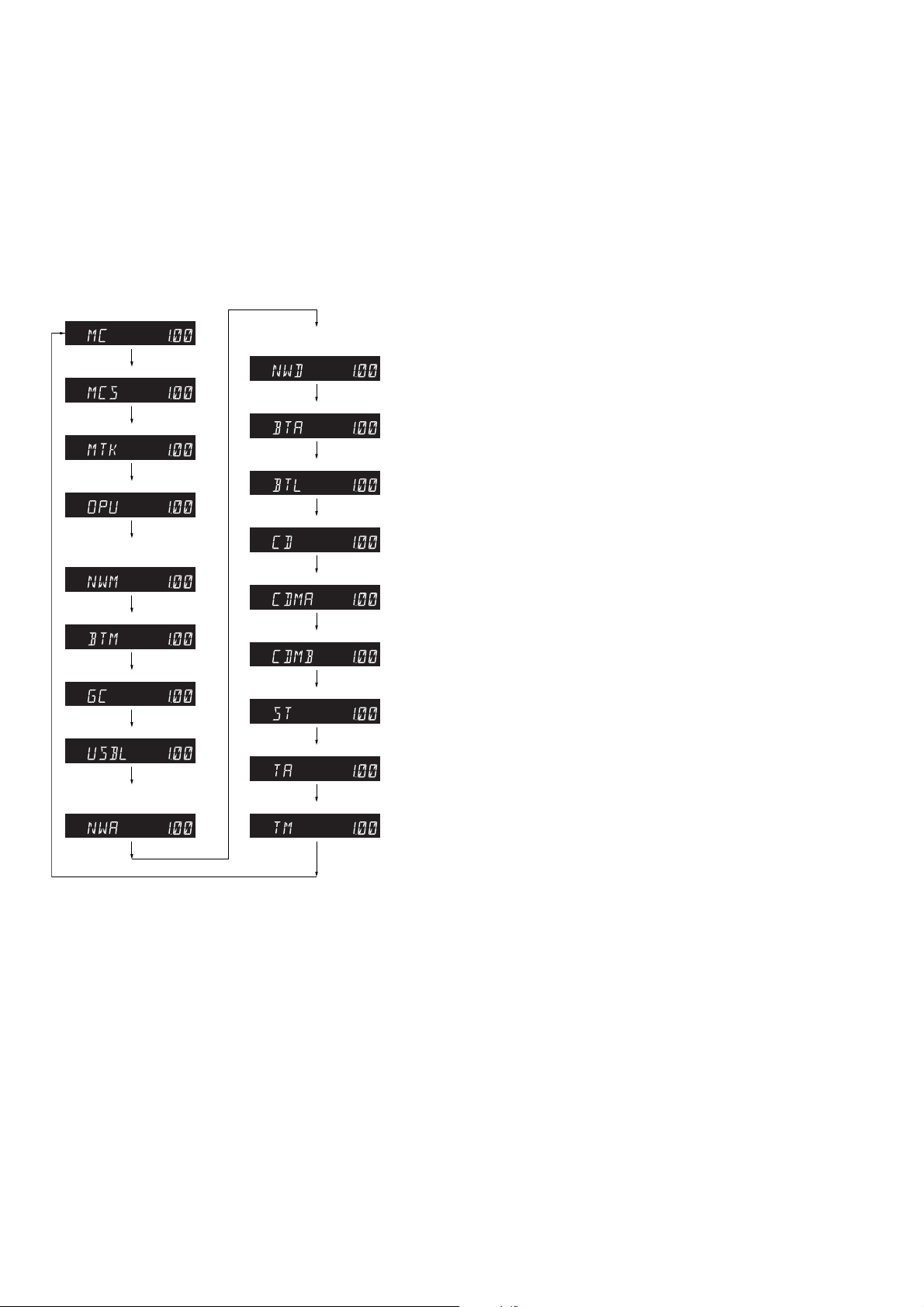
5. When pressing the [
> TUNE +] button again, the MC ver-
sion is displayed on the fl uorescent indicator tube.
6. Each time [
> TUNE +] button is pressed, tthe display
changes MCS version → MTK version → OPU version →
NWM version (HCD-SBT300W/SBT300WB only) → BTM
version → GC version → USBL version → NWA version
(HCD-SBT300W/SBT300WB only) → NWD version (HCDSBT300W/SBT300WB only) → BTA version → BTL version
→ CD version → CDMA version → CDMB version → ST
version → TA version → TM version this order, and returns to
the MC version display.
MC version
MCS version
MTK version
OPU version
NWM version (HCDSBT300W/SBT300WB only)
BTM version
GC version
USBL version
NWA version (HCDSBT300W/SBT300WB only)
STEREO
STEREO
STEREO
STEREO
STEREO
STEREO
STEREO
STEREO
STEREO
NWD version (HCDSBT300W/SBT300WB only)
BTA version
BTL version
CD version
CDMA version
CDMB version
ST version
TA version
TM version
STEREO
STEREO
STEREO
STEREO
STEREO
STEREO
STEREO
STEREO
STEREO
(Displayed values in the above fi gure are example)
DISC TRAY LOCK MODE
It can be unable to take sample disc out of disc tray in the shop.
Procedure:
1. Press the [?/1] button to turn the power on.
2. Press the [FUNCTION] button to turn the CD function.
3. Press the [Z] button to open the disc tray and set the CD.
4. Press the [Z] button to close the disc tray.
5. Press two buttons of the [x] and [Z] simultaneously for fi ve
seconds.
6. The message “LOCKED” is displayed on the fl uorescent indi-
cator tube and the disc tray is locked.
(Even if pressing the [Z] button, the message “LOCKED”
is displayed on the liquid crystal display and the disc tray is
locked)
Releasing method:
1. Press two buttons of the [x] and [Z] simultaneously for fi ve
seconds.
2. The message “UNLOCKED” is displayed on the fl uorescent
indicator tube and the disc tray is unlocked.
AM STEP CHANGE
(Except AEP and UK models)
It can change AM step interval into 9 kHz or 10 kHz.
Procedure:
1. Press the [
] button to turn the power on.
?/1
2. Press the [FUNCTION] button to turn the AM function.
3. Press the [
4. Press two buttons of the [FUNCTION] and [
] button to turn the power off.
?/1
] simultane-
?/1
ously.
5. The message “STEP 9” or “STEP 10” is displayed on the
fl uorescent indicator tube, and AM step interval changed.
CHECK VERSION DISPLAY
It can confi rm the MC, CD and NW version.
Procedure:
1. Press the [
] button to turn the power on.
?/1
2. Press two buttons of the [x] and [BASS BOOST] simultaneously for three seconds.
3. It enters the check version display mode, the MC version is
displayed on the fl uorescent indicator tube.
4. Each time [> TUNE +] button is pressed, the display changes CD version → NW version (HCD-SBT300W/SBT300WB
only) this order, and release from check version display mode.
7. When pressing the [x] button while the each version is dis-
played, year, month and day of the software creation is displayed. When pressing the [x] button again, the display returns to the each version display.
8. When pressing the [. TUNE −] button, “K 0 V0” is dis-
played on the fl uorescent indicator tube.
9. Each time a button is pressed, “K 0” value increases. However,
once a button is pressed, it is no longer taken into account.
When pressing the all buttons, display becomes “K10”.
10. “V0” value increases “V2”, “V4”, “V6” “V8”, “V0” if turn
the [VOLUME] knob clockwise, or it decreases “V8”, “V6”,
“V4”, “V2”, “V0” if turn the knob counterclockwise.
Releasing method:
Press two buttons of the [FUNCTION] and [. TUNE −] simultaneously for three seconds.
24
HCD-SBT100/SBT100B/SBT300W/SBT300WB
SECTION 4
ELECTRICAL CHECKS
TUNER SECTION
0 dB = 1 μV
FM AUTO STOP CHECK
signal
generator
unit
Procedure:
1. Press the [?/1] button to turn the power on.
2. Input the following signal from signal generator to FM antenna
input directly.
Carrier frequency : A = 87.5 MHz, B = 98 MHz, C = 108 MHz
Deviation : 75 kHz
Modulation : 1 kHz
ANT input : 35 dBu (EMF)
Note: Use 75 ohm coaxial cable to connect signal generator and the unit.
You cannot use video cable for checking.
Use signal generator whose output impedance is 75 ohm.
3. Press the [FUNCTION] button to turn the FM tuner function
and scan the input FM signal with automatic scanning.
4. Confi rm that input frequency of A, B and C detected and auto-
matic scanning stops.
When the station signal is received in good condition, automatic
scanning stops.
CD SECTION
Note:
1. CD block is basically constructed to operate without adjustment.
2. Use HLX-A1 disc (Part No. J-2501-307-A) unless otherwise indicated.
3. Use an oscilloscope with more than 10 MΩ impedance.
4. Clean the object lens by an applicator with neutral detergent when the
signal level is low than specifi ed value with the following check.
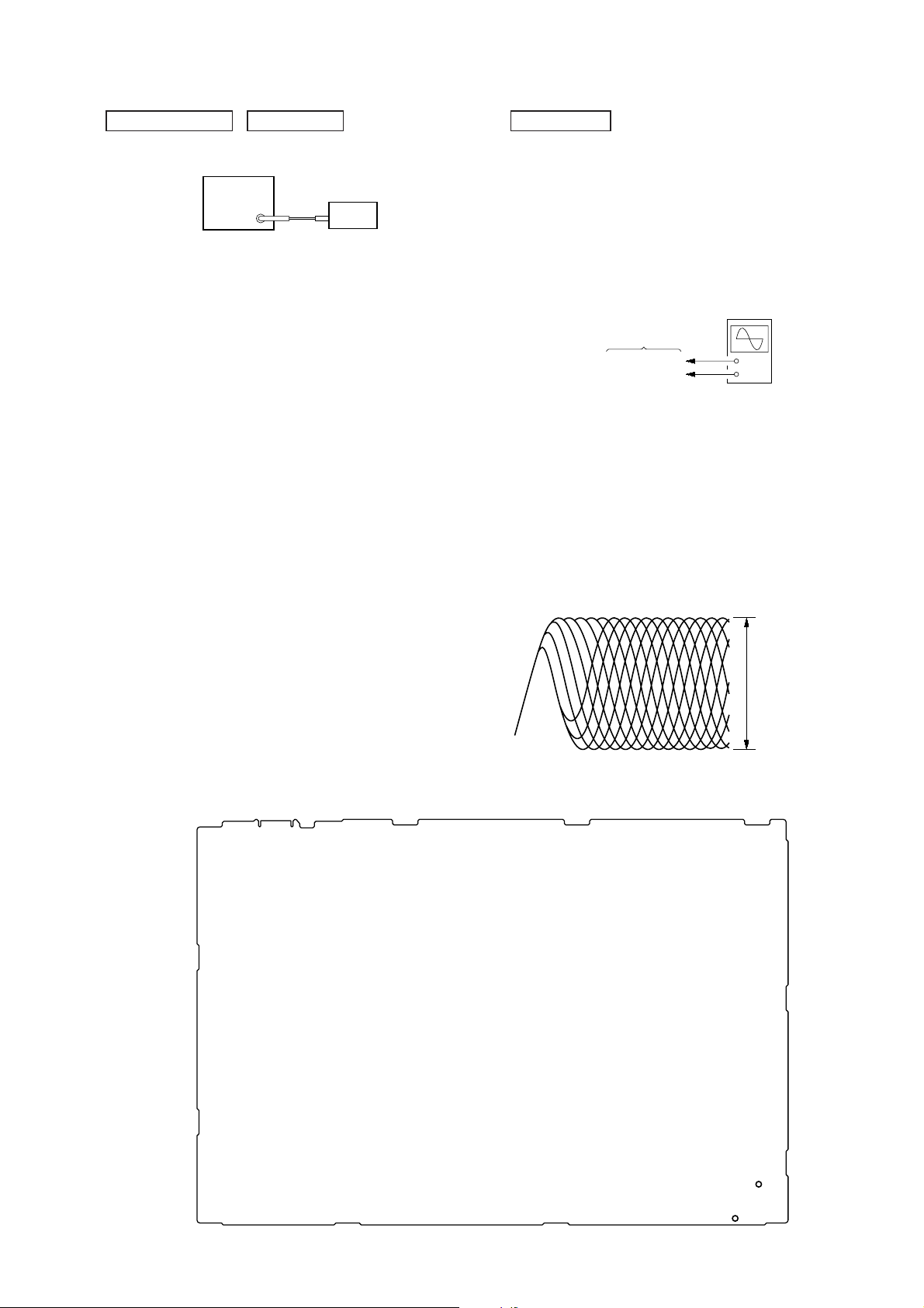
RF SIGNAL CHECK
oscilloscope
(DC range)
MAIN board
CL576 (RF)
CL573 (GND)
+
–
Procedure:
1. Connect the oscilloscope to CL576 (RF) and CL573 (GND) on
the MAIN board.
2. Press the [
] button to turn the power on.
?/1
3. Press the [FUNCTION] button to turn the CD function.
4. Press the [Z] button to open the disc tray and set the disc
(HLX-A1).
5. Press the [Z] button to close the disc tray.
6. Press the [u] button to playback.
7. Confi rm that oscilloscope waveform is as shown in the fi gure
below. (eye pattern)
A good eye pattern means that the diamond shape (◊) in the
center of the waveform can be clearly distinguished.
Connection Location:
– MAIN Board (Component Side) –
VOLT/DIV: 200 mV
TIME/DIV: 500 ns
level: 1.05 ± 0.45 Vp-p
CL573
(GND)
CL576
(RF)
25

HCD-SBT100/SBT100B/SBT300W/SBT300WB
MEMO
26
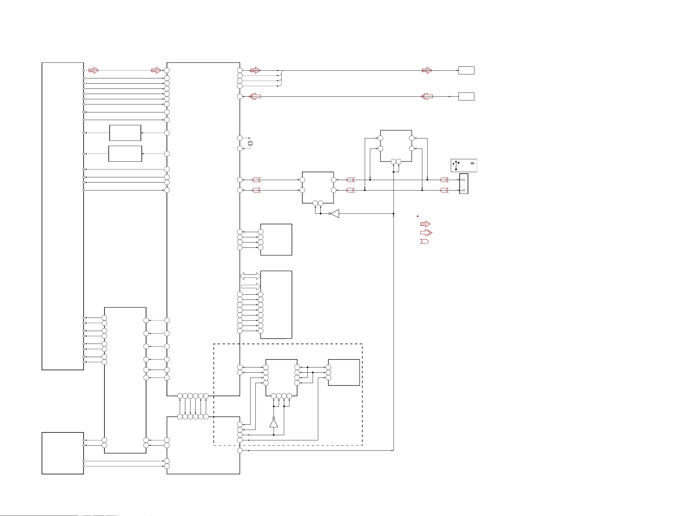
5-1. BLOCK DIAGRAM - CD Section -
OPTICAL PICK-UP BLOCK
(CMS-S76RFS7G)
RF
VOA/A
VOB/B
VOC/C
VOD/D
VOE/E+G
VOF/F+H
VC
PD
LD (780)
LD (650)
MSW
VR (780)
VR (650)
LIMIT
AUTOMATIC POWER
CONTROL (FOR CD)
Q891
AUTOMATIC POWER
CONTROL (FOR DVD)
Q881
SECTION 5
DIAGRAMS
RF AMP, SERVO/AUDIO PROCESSOR
123 R F I P
1 RF_C
128 R F _ B
127 R F _ A
2 RF_D
4 RF_F
3 RF_E
10 V20
13 MDI1
14 LDO1
15 LDO2
23 MSW
19 CD_VR
20 DVD_VR
44 LIMITSW
IC501
HCD-SBT100/SBT100B/SBT300W/SBT300WB
ASDATA0, ABCK,
ALRCK, ACLK
SIGNAL PATH
: CD PLAY
: AUDIO IN
: USB
ADIN
>001B
>002B
CN5004
DC 5V
2.1A MAX
3
2
(Page 28)
(Page 28)
D+
D–
X501
27MHz
ASDATA0
ABCK
ALRCK
ACLK
SERIAL FLASH
2
SO
5
SI
6
SCK33SF_CK
1
_CS30SF_CS#
IC502
USB DATA SWITCH
IC309
6B2
3B1
OE17OE2
1
Q303
USB CHARGER
SWITCH
IC308
6B2
3B1
5A2
2A1
5A2
2A1
OE17OE2
1
118ASDATA0
113ABCK
117ALRCK
112ACLK
106ADIN
8XTALO
7XTALI
25USB_DP
24USB_DM
31SF_DO
32SF_DI
MS-476 BOARD
SP+
SP–
SL+
SL–
TRK+
TRK–
FCS+
FCS–
LOAD+
LOAD–
FOCUS/TRACKING COIL DRIVE,
SPINDLE/SLED/LOADING MOTOR DRIVE
11 VOSL+
12 VOSL–
17 VOLD+
18 VOLD–
16 VOTK–
15 VOTK+
14 VOFC+
13 VOFC–
10 VOTR+
9VOTR–
IC851
4VINSL+
23VINLD
26VINTK
1VINFC
28MUTE
27BIAS
6FWD
7RVS
17 DMO
18 FMO
21 TRO
22 FOO
45 MUTE
11 VREFO
40
1
92 CDM FWD
93 CDM RVS
IFSDI
IFSDO
IFSCK
35
34
100
2
MTK DIN
MTK DOUT
IFCS#
42
41
95
94
MTK CS
MTK CLK
IFBSY
PRST#
38
3
MTK BUSY
MTK RESET
RD0 – RD15
RA0 – RA11 A0 – A11
85BA0
86BA1
82CAS#
83RAS#
47SDA 21O/I
48SCL
24CP IIC SDA
22CP IIC CLK
44CP SELECT
23CP IIC RESET
52USB CHARGE
DQ0 – DQ15
20
BA0
21
BA1
38
CLK72RCLK
16
WE80RWE#
17
CAS
18
RAS
15
LDQM61DQM0
39
UDQM70DQM1
DATA/CLOCK SIGNAL
1
11
4
8
Q202
SD-RAM
IC504
SWITCH
IC202
1I/O
4I/O
2I/O
3I/O
131C124C52C6
MFI
IC506
13
I2C_SDA
12
104O/I
32O/I
93O/I
3C
I2C_SCL
4
RESET
(SBT300W/SBT300WB)
LOAD_END_SW
UNLOAD_END_SW
HCD-SBT100/SBT100B/SBT300W/SBT300WB
91 CDM LOAD END SW
90 CDM UNLOAD END SW
SYSTEM CONTROLLER
IC101 (1/3)
2727
 Loading...