

Sony HCDSB-200 Service manual
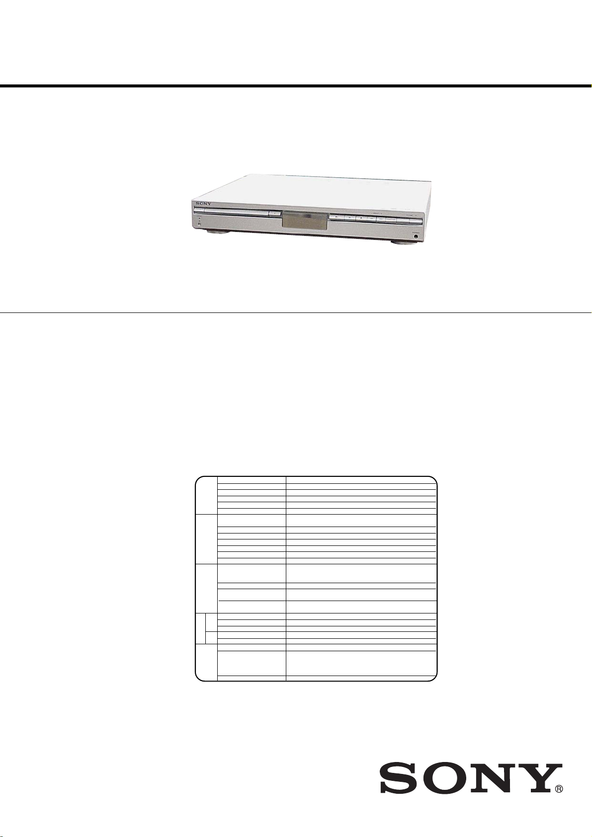
HCD-SB100/SB200
SERVICE MANUAL
Ver. 1.8 2006.02
Photo: HCD-SB100
• HCD-SB100/SB200 are the amplifier, DVD/CD and
tuner section in DAV-SB100/SB200.
Manufactured under license from Dolby Laboratories. “Dolby”, “Pro Logic”,
and the double-D symbol are trademarks of Dolby Laboratories.
Confidential Unpublished works. Copyright 1992-1997 Dolby
Laboratories. All rights reserved.
Manufactured under license from Digital Theater Systems, Inc.
US Pat. No. 5,451,942 5,956,674, 5,974,380, 5,978,762 and other
worldwide patents issued and pending. “DTS” and “DTS Digital Surround”
are registered trademarks of Digital Theater Systems, Inc. Copyright 1996,
2000 Digital Theater Systems, Inc. All rights reserved.
US Model
Canadian Model
HCD-SB100
AEP Model
UK Model
E Model
Australian Model
HCD-SB100/SB200
•Abbreviation
AUS: Australian model
CND : Canadian model
EA : Saudi Arabia model
EE : East European model
RU : Russian model
SP : Singapore model
SPECIFICATIONS
(SB100: US, CND models)
Power supply 120V AC, 60Hz
Power consumption 70W, No more than 1 W (120V AC) (at the power saving mode)
Mass kg
External dimensions (W x H x D) 430 x 70 x 383.5 mm
[General]
Operating conditions Temperature:5°C to 35°C, Operation status: Horizontal
Operating humidity 5% to 85%
Laser Semiconductor laser, wavelength 650 nm for VCD and DVD,
Emission duration Continuous
Signal system NTSC 525/60
Frequency response (audio) 2 Hz ~ 20 kHz (±1.0 dB)
[CD/DVD][Video][Amplifier]
Signal-to-noise ratio (audio) More than 75 dB (1 kHz, NOP, 20 kHz LPF/A-Filter)
Dynamic range (audio) More than 70 dB
Harmonic distortion (audio) 0.5 % (1 kHz, at 12W position) (20 kHz LPF/A-Filter)
Inputs (AUDIO IN):
Video output 1.0 V (p-p), 75 Ω, negative sync., RCA jack
S VIDEO OUT (Y) 1.0 V (p-p), 75 ohms, negative sync, Mini DIN 4-pin x 1
COMPONENT VIDEO OUT (Y) 1.0 V (p-p), 75 ohms, negative sync, RCA jack x 1
Tuning Range 87.5 - 108 MHz
Intermediate Frequency 10.7 MHz
[FM]
Signal-to Noise Ratio 60 dB (Mono)
Tuning Range 522 - 1,611 kHz
[Tuner]
AM
Intermediate Frequency 450 kHz
[MW]
Stereo mode 50W + 50W (8 Ω at 1 kHz, THD 10 %)
Surround mode Front:50W + 50W
(*
Depending on the sound mode
settings and the source, there
may be no sound output.)
Outputs PHONES: (32 Ω, 25mW)
4.7
wavelength 780 nm for CD
VIDEO
Sensitivity: 800 m V
Impedance: 50 kilohms
(C) 0.286 V (p-p) 75 ohms
(P
B/CB
)/(PR/CR) 0.7 V (p-p), 75 ohms, RCA jack x 2
Centre*: 50W
Surround*: 50W + 50W (8Ω at 1 kHz, THD 10 %)
Subwoofer*: 80W (4Ω at 50 Hz, THD 10 %)
– Continued on next page –
DVD RECEIVER
9-879-182-09
2006B16-1
© 2006.02
Sony Corporation
Home Audio Division
Published by Sony Techno Create Corporation

HCD-SB100/SB200
Ver. 1.1
(SB100: AEP, UK, RU, EE models) (SB100: EA, SP, AUS models)
Power supply 220-240V AC, 50/60Hz
Power consumption 70W, No more than 1 W (220-240V AC) (at the power saving mode)
Mass kg
External dimensions (W x H x D) 430 x 70 x 383.5 mm
[General]
Operating conditions Temperature:5°C to 35°C, Operation status: Horizontal
Operating humidity 5% to 85%
Laser Semiconductor laser, wavelength 650 nm for VCD and DVD,
Emission duration Continuous
Signal system PAL 625/50, NTSC 525/60
Frequency response (audio) 2 Hz ~ 20 kHz (±1.0 dB)
[CD/DVD][Video][Amplifier]
Signal-to-noise ratio (audio) More than 75 dB (1 kHz, NOP, 20 kHz LPF/A-Filter)
Dynamic range (audio) More than 70 dB
Harmonic distortion (audio) 0.5 % (1 kHz, at 12W position) (20 kHz LPF/A-Filter)
Inputs (AUDIO IN):
Video output 1.0 V (p-p), 75 Ω, negative sync., RCA jack
Tuning Range 87.5 - 108 MHz
Intermediate Frequency 10.7 MHz
[FM]
Signal-to Noise Ratio 60 dB (Mono)
Tuning Range 522 - 1,611 kHz
[Tuner]
AM
Intermediate Frequency 450 kHz
[MW]
Stereo mode 50W + 50W (8 Ω at 1 kHz, THD 10 %)
Surround mode Front:50W + 50W
(*
Depending on the sound mode
settings and the source, there
may be no sound output.)
Outputs PHONES: (32 Ω, 25mW)
4.7
wavelength 780 nm for CD
VIDEO
Sensitivity: 800 m V
Impedance: 50 kilohms
SCART (AUDIO IN):
Sensitivity: 800 m V
Impedance: 50 kilohms
EURO AV (TO TV)
Centre*: 50W
Surround*: 50W + 50W (8Ω at 1 kHz, THD 10 %)
Subwoofer*: 80W (4Ω at 50 Hz, THD 10 %)
Power supply 220-240V AC, 50/60Hz
Power consumption 70W, No more than 1 W (220-240V AC) (at the power saving mode)
Mass kg
External dimensions (W x H x D) 430 x 70 x 383.5 mm
[General]
Operating conditions Temperature:5°C to 35°C, Operation status: Horizontal
Operating humidity 5% to 85%
Laser Semiconductor laser, wavelength 650 nm for VCD and DVD,
Emission duration Continuous
Signal system PAL 625/50, NTSC 525/60
Frequency response (audio) 2 Hz ~ 20 kHz (±1.0 dB)
[CD/DVD][Video][Amplifier]
Signal-to-noise ratio (audio) More than 75 dB (1 kHz, NOP, 20 kHz LPF/A-Filter)
Dynamic range (audio) More than 70 dB
Harmonic distortion (audio) 0.5 % (1 kHz, at 12W position) (20 kHz LPF/A-Filter)
Inputs (AUDIO IN):
Video output 1.0 V (p-p), 75 Ω, negative sync., RCA jack
S VIDEO OUT (Y) 1.0 V (p-p), 75 ohms, negative sync, Mini DIN 4-pin x 1
COMPONENT VIDEO OUT (Y) 1.0 V (p-p), 75 ohms, negative sync, RCA jack x 1
Tuning Range 87.5 - 108 MHz
Intermediate Frequency 10.7 MHz
Signal-to Noise Ratio 60 dB (Mono)
[FM]
Frequency Response (AUS) 150 - 10,000 Hz
[Tuner]
Tuning Range 522 - 1,611 kHz
AM
Intermediate Frequency 450 kHz
[MW]
Stereo mode 50W + 50W (8 Ω at 1 kHz, THD 10 %)
Surround mode Front:50W + 50W (THD 10 %)
(*
Depending on the sound mode
settings and the source, there
may be no sound output.)
Output PHONES: (32 Ω, 25mW)
4.7
wavelength 780 nm for CD
VIDEO
Sensitivity: 800 m V
Impedance: 50 kilohms
(C) 0.286 V (p-p) 75 ohms
(P
B/CB
Centre*: 50W
Surround*: 50W + 50W (8Ω at 1 kHz, THD 10 %)
Subwoofer*: 80W (4Ω at 50 Hz, THD 10 %)
)/(PR/CR) 0.7 V (p-p), 75 ohms, RCA jack x 2
(SB200: AEP, UK, RU, EE models) (SB200: SP, AUS models)
Power supply 220-240V AC, 50/60Hz
Power consumption 100W, No more than 1 W (220-240V AC) (at the power saving mode)
Mass kg
External dimensions (W x H x D) 430 x 70 x 370 mm
[General]
Operating conditions Temperature:5°C to 35°C, Operation status: Horizontal
Operating humidity 5% to 85%
Laser Semiconductor laser, wavelength 650 nm for VCD and DVD,
Emission duration Continuous
Signal system PAL, NTSC
Frequency response (audio) 2 Hz ~ 20 kHz (±1.0 dB)
[CD/DVD][Video][Amplifier]
Signal-to-noise ratio (audio) More than 75 dB (1 kHz, NOP, 20 kHz LPF/A-Filter)
Dynamic range (audio) More than 70 dB
Harmonic distortion (audio) 0.5 % (1 kHz, at 12W position) (20 kHz LPF/A-Filter)
Inputs (AUDIO IN):
Video output 1.0 V (p-p), 75 Ω, negative sync., RCA jack
Tuning Range 87.5 - 108 MHz
Intermediate Frequency 10.7 MHz
[FM]
Signal-to Noise Ratio 60 dB (Mono)
[Tuner]
Tuning Range 522 - 1,611 kHz
AM
Intermediate Frequency 450 kHz
[MW]
Stereo mode 80W + 80W (6 Ω at 1 kHz, THD 10 %)
Surround mode Front: 80W + 80W
(*
Depending on the sound mode
settings and the source, there
may be no sound output.)
Outputs PHONES: (32 Ω, 25mW)
4.9
wavelength 780 nm for CD
VIDEO
Sensitivity: 800 m V
Impedance: 50 kilohms
SCART (AUDIO IN):
Sensitivity: 800 m V
Impedance: 50 kilohms
EURO AV (TO TV)
Centre*: 80W
Surround*: 80W + 80W (6Ω at 1 kHz, THD 10 %)
Subwoofer*: 150W (3Ω at 50 Hz, THD 10 %)
Power supply 220-240V AC, 50/60Hz
Power consumption 100W, No more than 1 W (220-240V AC) (at the power saving mode)
Mass kg
External dimensions (W x H x D) 430 x 70 x 370 mm
[General]
Operating conditions Temperature:5°C to 35°C, Operation status: Horizontal
Operating humidity 5% to 85%
Laser Semiconductor laser, wavelength 650 nm for VCD and DVD,
Emission duration Continuous
Signal system PAL, NTSC
Frequency response (audio) 2 Hz ~ 20 kHz (±1.0 dB)
[CD/DVD][Video][Amplifier]
Signal-to-noise ratio (audio) More than 75 dB (1 kHz, NOP, 20 kHz LPF/A-Filter)
Dynamic range (audio) More than 70 dB
Harmonic distortion (audio) 0.5 % (1 kHz, at 12W position) (20 kHz LPF/A-Filter)
Inputs (AUDIO IN):
Video output 1.0 V (p-p), 75 Ω, negative sync., RCA jack
S VIDEO OUT (Y) 1.0 V (p-p), 75 ohms, negative sync, Mini DIN 4-pin x 1
COMPONENT VIDEO OUT (Y) 1.0 V (p-p), 75 ohms, negative sync, RCA jack x 1
Tuning Range 87.5 - 108 MHz
Intermediate Frequency 10.7 MHz
[FM]
Signal-to Noise Ratio 60 dB (Mono)
Tuning Range 522 - 1,611 kHz
[Tuner]
AM
Intermediate Frequency 450 kHz
[MW]
Stereo mode 80W + 80W (6 Ω at 1 kHz, THD 10 %)
Surround mode Front:80W + 80W
Depending on the sound mode
(*
settings and the source, there
may be no sound output.)
Outputs PHONES: (32 Ω, 25mW)
Designs and specifications are subject to change without notice.
4.9
wavelength 780 nm for CD
VIDEO
Sensitivity: 800 m V
Impedance: 50 kilohms
(C) 0.286 V (p-p) 75 ohms
(P
B/CB
)/(PR/CR) 0.7 V (p-p), 75 ohms, RCA jack x 2
Centre*: 80W
Surround*: 80W + 80W (6Ω at 1 kHz, THD 10 %)
Subwoofer*: 150W (3Ω at 50 Hz, THD 10 %)
2

HCD-SB100/SB200
1.5 k
Ω
0.15 µF
AC
voltmeter
(0.75 V)
To Exposed Metal
Parts on Set
Earth Ground
Ver. 1.1
Laser component in this product is capable of emitting radiation
exceeding the limit for Class 1.
This appliance is classified as
a CLASS 1 LASER product.
The CLASS 1 LASER
PRODUCT MARKING is
located on the rear exterior.
CAUTION
Use of controls or adjustments or performance of procedures
other than those specified herein may result in hazardous radiation
exposure.
Notes on chip component replacement
• Never reuse a disconnected chip component.
• Notice that the minus side of a tantalum capacitor may be
damaged by heat.
Flexible Circuit Board Repairing
• Keep the temperature of the soldering iron around 270 °C
during repairing.
• Do not touch the soldering iron on the same conductor of the
circuit board (within 3 times).
• Be careful not to apply force on the conductor when soldering
or unsoldering.
SAFETY CHECK-OUT
After correcting the original service problem, perform the following
safety check before releasing the set to the customer:
Check the antenna terminals, metal trim, “metallized” knobs, screws,
and all other exposed metal parts for AC leakage.
Check leakage as described below.
LEAKAGE TEST
The AC leakage from any exposed metal part to earth ground and
from all exposed metal parts to any exposed metal part having a
return to chassis, must not exceed 0.5 mA (500 microamperes.).
Leakage current can be measured by any one of three methods.
1. A commercial leakage tester, such as the Simpson 229 or RCA
WT -540A. Follow the man ufacturers’ instructions to use these
instruments.
2. A battery-operated A C milliammeter . The Data Precision 245
digital multimeter is suitable for this job.
3. Measuring the voltage drop across a resistor by means of a
VOM or battery-operated A C voltmeter. The “limit” indication
is 0.75 V, so analog meters must hav e an accurate low-volta ge
scale. The Simpson 250 and Sanwa SH-63Trd are examples
of a passive VOM that is suitable. Nearly all battery operated
digital multimeters that have a 2 V AC range are suitable. (See
Fig. A)
SAFETY-RELATED COMPONENT WARNING!!
COMPONENTS IDENTIFIED BY MARK 0 OR DOTTED LINE
WITH MARK 0 ON THE SCHEMATIC DIAGRAMS AND IN
THE PARTS LIST ARE CRITICAL TO SAFE OPERATION.
REPLACE THESE COMPONENTS WITH SONY PARTS WHOSE
PART NUMBERS APPEAR AS SHOWN IN THIS MANUAL OR
IN SUPPLEMENTS PUBLISHED BY SONY.
Fig. A. Using an AC voltmeter to check AC leakage.
ATTENTION AU COMPOSANT AYANT RAPPORT
À LA SÉCURITÉ!
LES COMPOSANTS IDENTIFIÉS PAR UNE MARQUE 0 SUR
LES DIAGRAMMES SCHÉMATIQUES ET LA LISTE DES
PIÈCES SONT CRITIQUES POUR LA SÉCURITÉ DE
FONCTIONNEMENT. NE REMPLACER CES COM- POSANTS
QUE PAR DES PIÈCES SONY DONT LES NUMÉROS SONT
DONNÉS DANS CE MANUEL OU DANS LES SUPPLÉMENTS
PUBLIÉS PAR SONY.
3

HCD-SB100/SB200
Ver. 1.1
TABLE OF CONTENTS
1. SERVICING NOTES ................................................ 5
2. GENERAL ................................................................... 6
3. DISASSEMBLY
3-1. Disassembly Flow ........................................................... 12
3-2. Case ................................................................................. 13
3-3. Front Panel Assy Section ................................................. 13
3-4. POWER Board ................................................................ 14
3-5. DVD Board...................................................................... 15
3-6. DVD Mechanism Deck ................................................... 16
3-7. Tuner Pack ....................................................................... 16
3-8. AMP Board...................................................................... 17
4. ELECTRICAL TROUBLE
SHOOTING GUIDE.................................................. 18
5. TEST MODE ............................................................... 42
6. ELECTRICAL ADJUSTMENT ............................. 43
7. DIAGRAMS
7-1. Block Diagram – DVD Section –................................... 46
– AUDIO Section –.......................................................... 47
– POWER Section – ........................................................ 48
7-2. Printed Wiring Board
– AMP Section SB100 (Component Side) – ................... 49
7-3. Printed Wiring Board
– AMP Section SB100 (Conductor Side) –..................... 50
7-4. Printed Wiring Board
– AMP Section SB200 (Component Side) – ................... 51
7-5. Printed Wiring Board
– AMP Section SB200 (Conductor Side) –..................... 52
7-6. Schematic Diagram – AMP Section (1/6) – ................... 53
7-7. Schematic Diagram – AMP Section (2/6) – ................... 54
7-8. Schematic Diagram – AMP Section (3/6) – ................... 55
7-9. Schematic Diagram – AMP Section (4/6) (SB100) –..... 56
7-10. Schematic Diagram – AMP Section (5/6) (SB200) –..... 57
7-11. Schematic Diagram – AMP Section (6/6) – ................... 58
7-12. Printed Wiring Board – DVD Section – ......................... 59
7-13. Schematic Diagram – DVD Section (1/3) – ................... 60
7-14. Schematic Diagram – DVD Section (2/3) – ................... 61
7-15. Schematic Diagram – DVD Section (3/3) – ................... 62
7-16. Printed Wiring Board – FRONT Section –..................... 63
7-17. Schematic Diagram – FRONT Section – ....................... 64
7-18. Printed Wiring Board – POWER Section (SB100) – ..... 65
7-19. Printed Wiring Board – POWER Section (SB200) – ..... 66
7-20. Schematic Diagram
– POWER Section (1/2) (SB100) –................................. 67
7-21. Schematic Diagram
– POWER Section (2/2) (SB200) –................................. 68
8. EXPLODED VIEWS
8-1. Overall Section ................................................................ 77
8-2. Chassis Section................................................................ 78
8-3. DVD Mechanism Section................................................ 79
9. ELECTRICAL PARTS LIST .................................. 80
4

SECTION 1
SERVICING NOTES
NOTES ON HANDLING THE OPTICAL PICK-UP BLOCK
OR BASE UNIT
The laser diode in the optical pick-up block may suffer electrostatic
break-down because of the potential difference generated by the
charged electrostatic load, etc. on clothing and the human body.
During repair, pay attention to electrostatic break-down and also
use the procedure in the printed matter which is included in the
repair parts.
The flexible board is easily damaged and should be handled with
care.
NOTES ON LASER DIODE EMISSION CHECK
The laser beam on this model is concentrated so as to be focused on
the disc reflective surface by the objective lens in the optical pickup block. Therefore, when checking the laser diode emission,
observe from more than 30 cm away from the objective lens.
LASER DIODE AND FOCUS SEARCH OPERATION
CHECK
HCD-SB100/SB200
Ver. 1.5
Carry out the “S curve check” in “CD section adjustment” and check
that the S curve waveform is output several times.
Attention when IC101 (system controller) exchanged.
When IC101 (system controller) is exchanged, discharged C107.
The method of discharging C107, 4 pin and 5 pin of PN105 are
shorted only at the moment.
4
5
short
5
HCD-SB100/SB200
•Abbreviation
AUS: Australian model
CND : Canadian model
EA : Saudi Arabia model
EE : East European model
RU : Russian model
SP : Singapore model
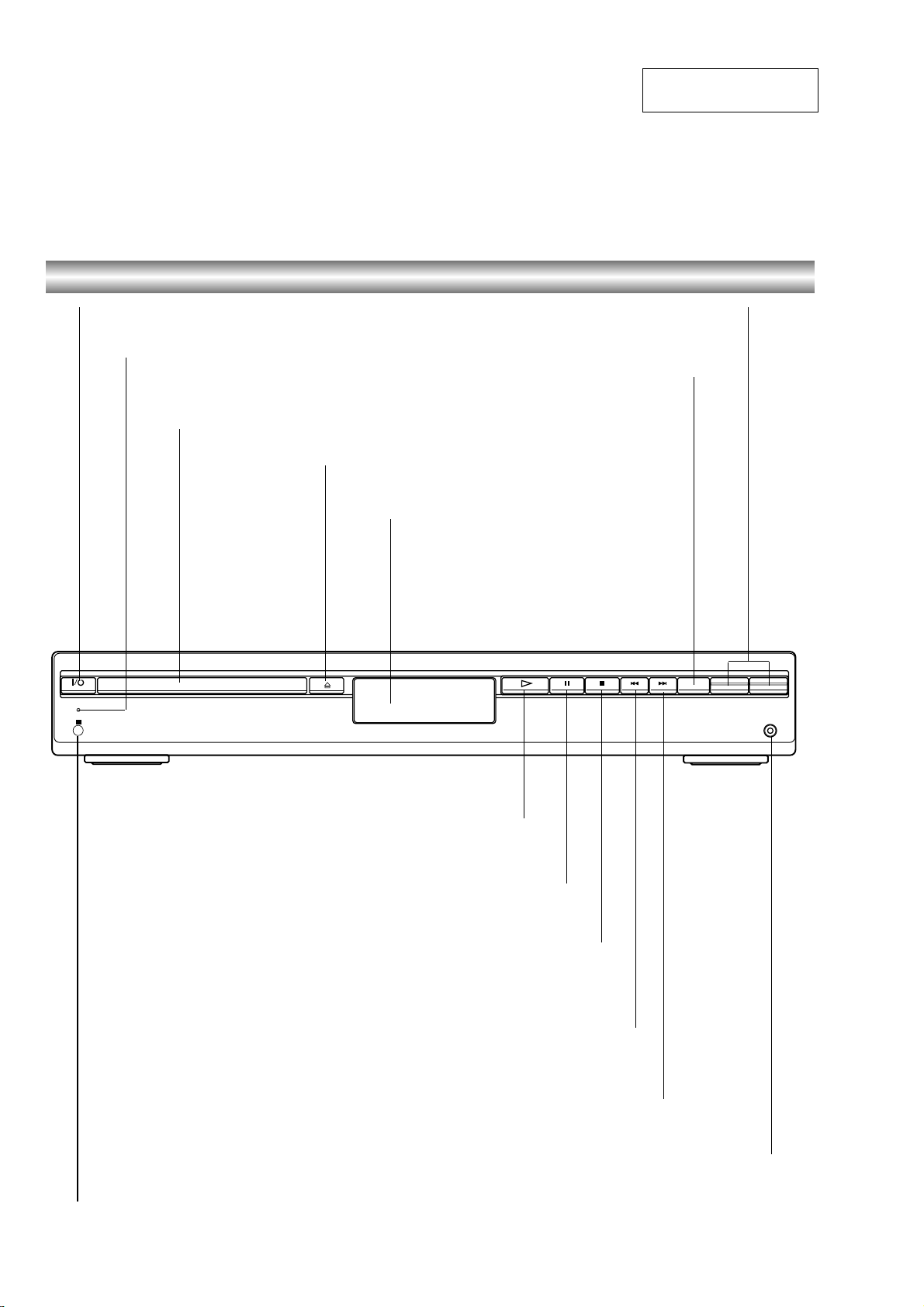
Front Panel Controls
SECTION 2
GENERAL
This section is extracted
from instruction manual.
@ / 1 (POWER) indicator
Switches the DVD Receiver ON and OFF.
STANDBY indicator
Lights red when the receiver
is in Standby mode (off).
Disc T ray
Insert a disc here.
STANDBY
IR
Press “+” to increase volume or press “-” to
To select the Receiver’s source.
OPEN/CLOSE ( )
A
Opens or closes the disc tray.
Display window
VOLUME Control
decrease the volume.
FUNCTION
(FM, AM, VIDEO, TV or
CD/DVD)
-
PRESET
+
FUNCTION
-
VOLUME
+
PHONES
Pause playback of a disc temporarily.
DVD: Go to beginning of current chapter/track or to previous
Remote Sensor
Point the DVD receiver remote control here.
PLAY (
To play back a disc.
Stops playback of a disc.
RADIO:
To select preset station you want.
DVD: Go to NEXT chapter/track.
RADIO:
To select preset station you want.
H
)
PAUSE (X)
x
STOP (
Reverse SKIP ( )
)
.
chapter/track.
Forward SKIP ( )
>
PHONES
To connect headphones.
6

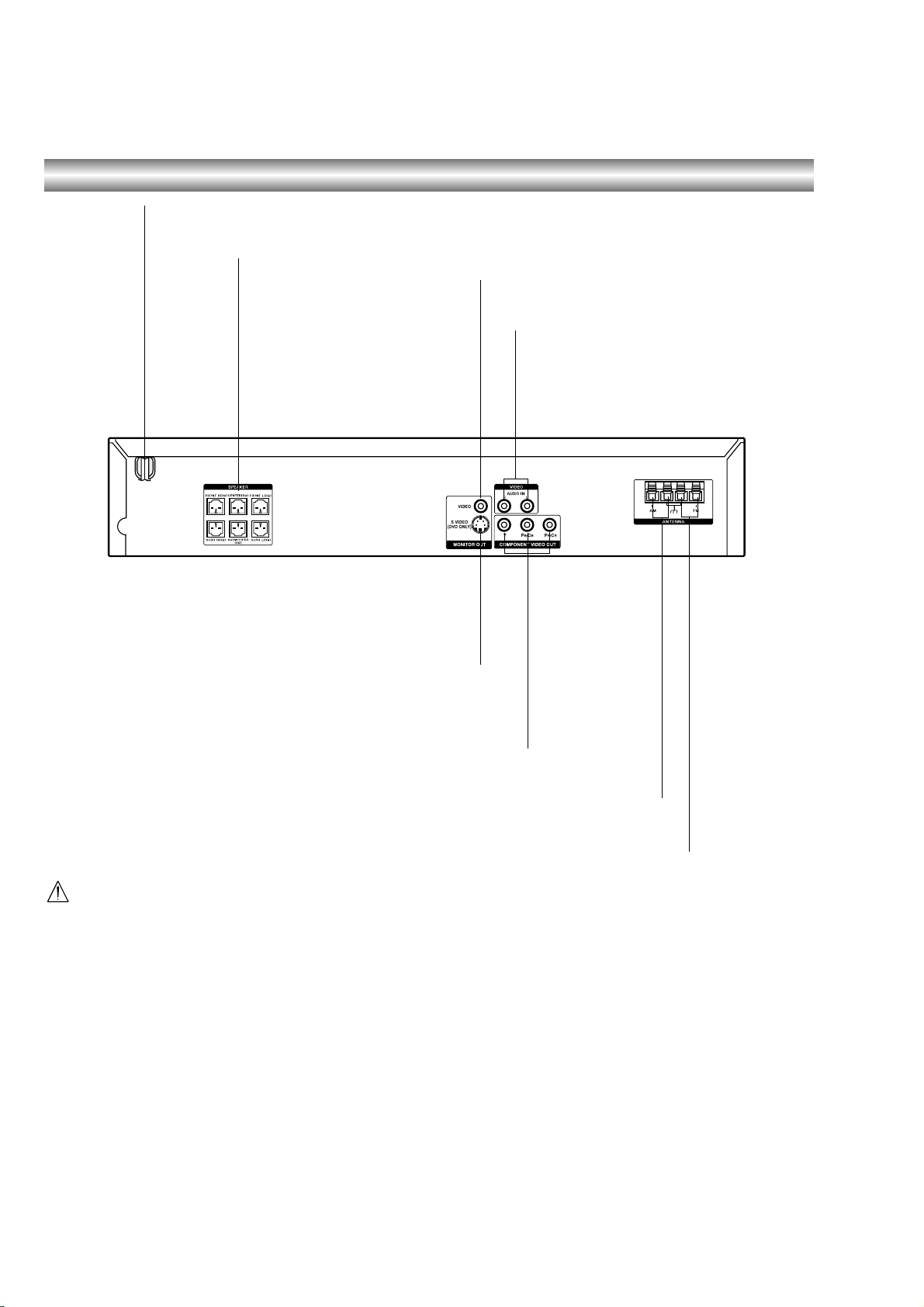
(SB100: AEP, UK, RU, EE models)
Rear Panel Connections
AC Power Cord
Plug into the power source.
HCD-SB100/SB200
EURO AV OUTPUT (TO TV)
Connect to your TV set.
MONITOR OUT (VIDEO)
Connect to a TV with video input.
VIDEO (AUDIO IN L/R)
Connect the audio output of an external
source (VCR, LD player, etc).
Connect the AM Loop antenna to this terminal.
SPEAKER CONNECTORS
Connect the six supplied speakers
to these terminals.
Do not touch the inner pins of the jacks on the rear
panel. Electrostatic discharge may cause permanent
damage to the unit.
AM LOOP ANTENNA CONNECTORS
FM ANTENNA CONNECTOR
Connect the FM antenna to this terminal.
7
HCD-SB100/SB200
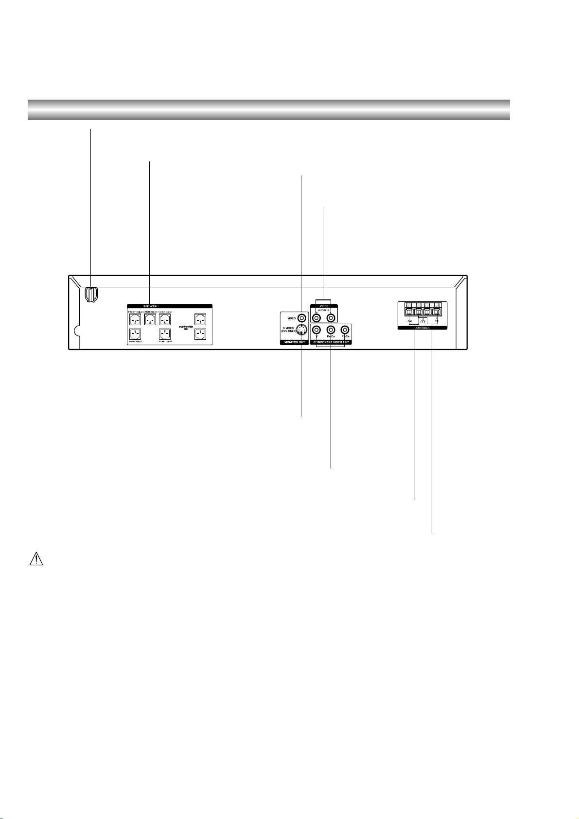
(SB100: US, CND, EA, SP, AUS models)
Rear Panel Connections
AC Power Cord
Plug into the power source.
SPEAKER CONNECTORS
Connect the six supplied
speakers to these terminals.
MONITOR OUT (VIDEO)
Connect to a TV with video input.
VIDEO (AUDIO IN L/R)
Connect the audio output of an external
source (VCR, LD player, etc).
MONITOR S VIDEO OUT (DVD Only)
Connect to a S Video Input on TV.
FOR DVD VIEWING ONLY.
COMPONENT VIDEO OUT (Y P
Connect to a TV with Y P
FOR DVD VIEWING ONLY.
Connect the AM Loop antenna to this terminal.
Do not touch the inner pins of the jacks on the rear
panel. Electrostatic discharge may cause permanent
damage to the unit.
B/CBPR/CR
B/CBPR/CR
AM LOOP ANTENNA CONNECTORS
Connect the FM antenna to this terminal.
)
inputs.
FM ANTENNA CONNECTORS
8

(SB200: AEP, UK, RU, EE models)
Rear Panel Connections
AC Powe r Cord
Plug into the power source.
HCD-SB100/SB200
EURO AV OUTPUT (TO TV)
Connect to your TV set.
MONITOR OUT (VIDEO)
Connect to a TV with video input.
VIDEO (AUDIO IN R/L)
Connect the audio output of an external
source (VCR, LD player, etc).
Connect the AM Loop antenna to this terminal.
SPEAKER CONNECTORS
Connect the six supplied speakers
to these terminals.
Do not touch the inner pins of the jacks on the rear
panel. Electrostatic discharge may cause permanent
damage to the unit.
AM LOOP ANTENNA CONNECTORS
FM ANTENNA CONNECTOR
Connect the FM antenna to this terminal.
9
HCD-SB100/SB200
(SB200: SP, AUS models)
Rear Panel Connections
AC Power Cord
Plug into the power source.
SPEAKER CONNECTORS
Connect the six supplied
speakers to these terminals.
MONITOR OUT (VIDEO)
Connect to a TV with video input.
VIDEO (AUDIO IN L/R)
Connect the audio output of an external
source (VCR, LD player, etc).
MONITOR S VIDEO OUT (DVD ONLY)
Connect to a S Video Input on TV.
FOR DVD VIEWING ONLY.
COMPONENT VIDEO OUT (Y P
Connect to a TV with Y P
FOR DVD VIEWING ONLY.
Connect the AM Loop antenna to this terminal.
Do not touch the inner pins of the jacks on the rear
panel. Electrostatic discharge may cause permanent
damage to the unit.
B/CBPR/CR
B/CBPR/CR
AM LOOP ANTENNA CONNECTORS
Connect the FM antenna to this terminal.
)
inputs.
FM ANTENNA CONNECTORS
10

SONY TV DIRECT
Select the output source to DVD directly.
TV @ / 1
Switches TV ON and OFF.
@ / 1
Switches DVD Receiver ON and OFF.
AUTO FORMAT DIRECT
Selects sound mode between A.F.D.
AUTO, PRO LOGIC, PLII MOVIE and
PLII MUSIC.
MODE
Selects sound mode between FLAT,
ROCK, POP, JAZZ, CLASSIC and
NEWS.
FUNCTION
To select the Receiver’s source.
(FM, AM, VIDEO, TV or CD/DVD)
Z
Opens and closes the disc tray.
DSGX
Switches DSGX ON and OFF.
0-9 numerical buttons
Selects numbered options in a menu.
>10/ TV ENTER
Used to control TV.
SLOW t/
TUNING-
For picture search or slow playback backward.
To tune in the desired station.
SLOW T/
TUNING+
For picture search or slow playback
forward.
To tune in the desired station.
Playback Control Buttons
• H (PLAY)
Starts playback.
• X (PAUSE)
Pause playback or recording temporarily .
• x (STOP)
Stops playback.
DVD MENU
Accesses menu on a DVD disc.
DISPLAY
To display remaining time between
Chapter and title.
To check the RDS service programme (PS).
VOLUME (+/-)
Adjusts speaker volume.
CLEAR
Removes a track number on the program
menu.
RETURN
Returns the setup menu.
DIMMER
To change the brightness of the display
window.
TV/VIDEO
Selects the TV’s source.
SLEEP
To place the unit in the Sleep mode.
TUNER/BAND
Selects the DVD Receiver’s tuner as the
listening choice. (FM and AM bands)
MUTING
Momentarily silence the speaker of the
DVD Receiver.
TUNER MENU
Memorize a radio station frequency
into the tuner.
Press to clear preset stations from the
tuner memory.
PROGRAM
Enters to the programme edit mode or
exits from that.
REPEAT
Repeat chapter, track, title, all.
FM MODE
To change between MONO and STEREO
modes.
TV
To control TVs with the Remote.
AUDIO
Selects an audio language (DVD) or an
audio channel (CD).
ANGLE
Selects a DVD camera angle if available.
SUBTITLE
Selects a subtitle language.
PREV/PRESET-
Go to beginning of current chapter or
track or go to previous chapter or track.
Select programme of Tuner.
NEXT/PRESET+
Go to next chapter or track.
Select programme of Tuner.
DVD T OP MENU
Displays the disc’s Title menu, if available.
B/b/V/v (left/right/up/down)
Selects an option in the menu.
ENTER
Acknowledges menu selection.
DVD DISPLAY
Accesses On-Screen display.
TV VOL +/–
Adjusts TV’s volume.
TV CH +/–
Selects TV’s channel.
DVD SETUP
Accesses or removes DVD setup menu.
Remote Control
HCD-SB100/SB200
11

HCD-SB100/SB200
Ver. 1.1
SECTION 3
DISASSEMBLY
•This set can be disassembled in the order shown below.
• : In order to remove set AMP board please remove POWER board and DVD board.
3-1. DISASSEMBLY FLOW
SET
3-2. CASE
(Page 13)
3-3. FRONT PANEL ASSY
SECTION
(Page 13)
3-6. DVD MECHANISM
DECK
(Page 16)
3-4. POWER BOARD
(Page 14)
3-8. AMP BOARD
(Page 17)
3-5. DVD BOARD
(Page 15)
3-7. TUNER P A CK
(Page 16)
12

• Follow the disassembly procedure in the numerical order given.
s
3-2. CASE
2
two case screws
4
case
3
two screws
HCD-SB100/SB200
1
two case screw
Ver. 1.1
3-3. FRONT PANEL ASSY SECTION
1
w
ire (flat type)
23p (PN101)
3
two
claws
3
six
claws
4
front panel assy section
3
five
claws
2
w
ire (flat type)
24p (PN102)
3
two
3
claws
two
claws
3
three
claws
13
HCD-SB100/SB200
r
Ver. 1.1
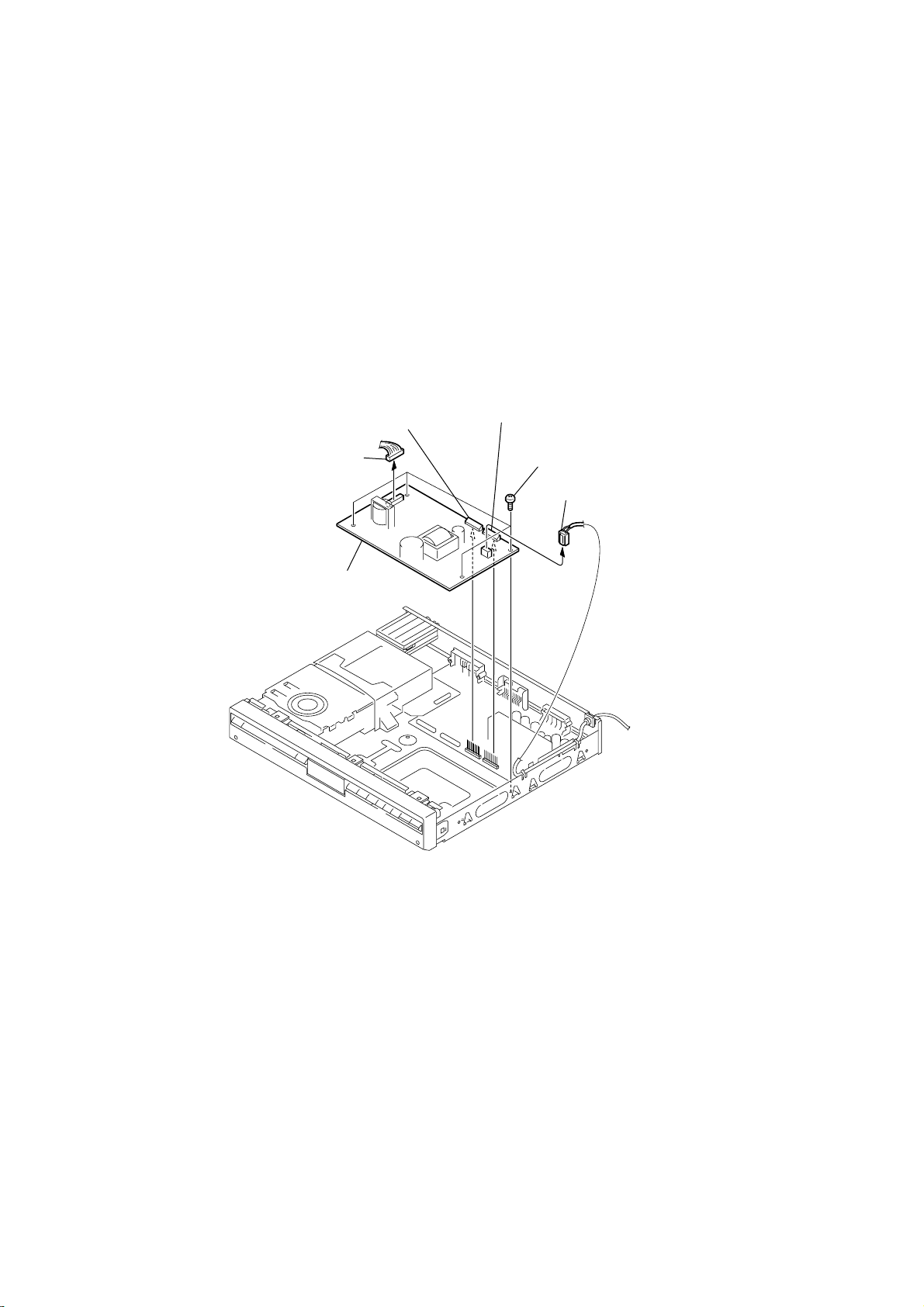
3-4. POWER BOARD
1
connector
(CN903)
5
connector
(CN902)
4
connector
(CN901)
3
four screws
6
POWER board
2
connecto
(PN901)
14

3-5. DVD BOARD
1
two screws
2
cover
3
23p (PDM01)
w
ire (flat type)
4
w
ire (flat type)
11p (PDM02)
HCD-SB100/SB200
Ver. 1.1
9
DVD board
6
four screws
8
connector
(PDA03)
7
connector
(PDA02)
5
connector
(CN903)
15

HCD-SB100/SB200
Ver. 1.1
3-6. DVD MECHANISM DECK
7
DVD mechanism deck
8
two
claws
9
door DVD
1
two screws
6
screw
2
cover
3
w
ire (flat type)
23p (PDM01)
4
w
ire (flat type)
11p (PDM02)
5
screw
3-7. TUNER PACK
1
w
ire (flat type)
12p (CON01)
3
tuner pack
2
two screws
16
s
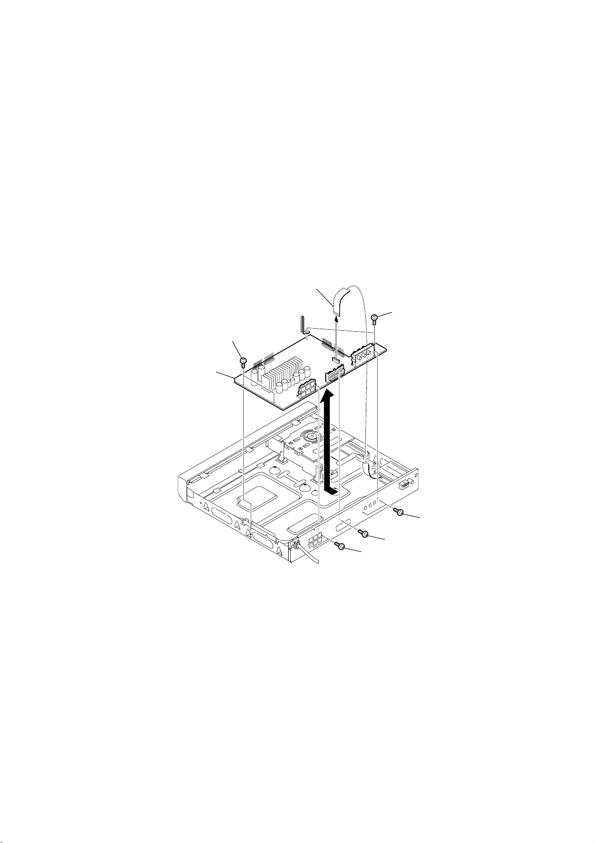
3-8. AMP BOARD
1
w
ire (flat type)
12p (PN103)
2
two screws
HCD-SB100/SB200
Ver. 1.1
7
AMP board
3
two screws
6
two screws
5
screw
4
two screw
17

HCD-SB100/SB200
Ver. 1.1
4-1. AUDIO PART
1. POWER CHECK FLOW
INSERT
POWER CORD.
SECTION 4
ELECTRICAL TROUBLE SHOOTING GUIDE
TURN ON
THE RED LED?
YES
TURN POWER ON.
IS POWER ON?
YES
DOES INITIAL
READ WORK?
YES
NO
NO
NO
CHECK POWER PLUG
AND POWER SUPPLY CIRCUIT.
CHECK POWER SUPPLY CIRCUIT.
CHECK LASER CIRCUIT.
CHECK FOCUS CIRCUIT.
DOES IT PLAY?
YES
DOES IT OUTPUT
AUDIO?
YES
OK
NO
NO
CHECK DISC.
CHECK TRACKING SERVO CIRCUIT.
CHECK AUDIO CIRCUIT.
18
2. AUDIO µ.COM CIRCUIT
POWER ON
HCD-SB100/SB200
Ver. 1.1
Does CD/DVD
appear at FLD?
YES
Does LOADING
appear at FLD?
NO
YES
Does no Dise or
Time appear at FLD?
NO
YES
Check if DVD an Audio
Micom Interface is OK.
Check power.
NO
YES
NO
Does it appear
DVD Error at
FLD?
YES
Check
Connector(PN902)if
is normally.
NO
YES
Check power part
of Main B/D.
YES
Check oscillator
of x101.
YES
NO
NO
NO
Reconnet it.
Refer to SMPS
Refer to oscillator
Circuit.
Does other function
name appear at FLD?
NO
YES
OK.
Check DVD Module.
Check SMPS.
Check if IC101
PIN1 is High.
YES
Check if IC101
PIN11 is High.
YES
Check if IC101 PIN
17, 46, 72, 90 is high
(5V).
YES
Check if IC101
PIN26 is High.
YES
Replace IC101.
NO
NO
NO
NO
Check DVD Reset Waveform.
Check IC101 Reset Wavefrom.
Check 5V line.
Check Power dection Circuit.
19

HCD-SB100/SB200
Ver. 1.1
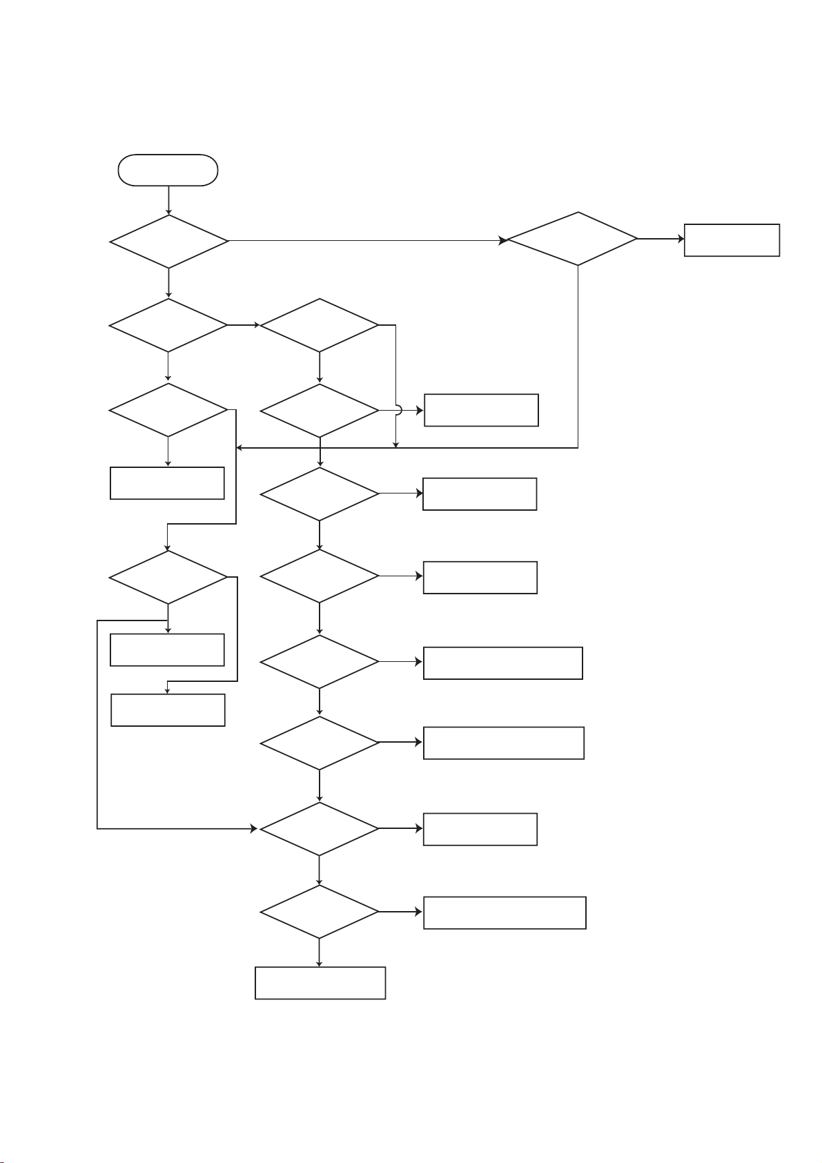
3. FRONT CIRCUIT (1/2)
20
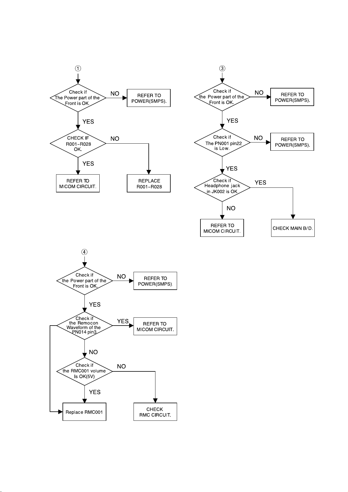
4. FRONT CIRCUIT (2/2)
HCD-SB100/SB200
Ver. 1.1
21

HCD-SB100/SB200
Ver. 1.1
4-2. DVD PART
1. POWER CHECK FLOW
YES
YES
YES
NO
NO
NO
YES
YES
YES
PDM02
PDM01
PDA02
NO
NO
NO
NO
Does other function
name at FLD?
NO
YES
YES
PDA01
YES
NO
PDA03
YES
22
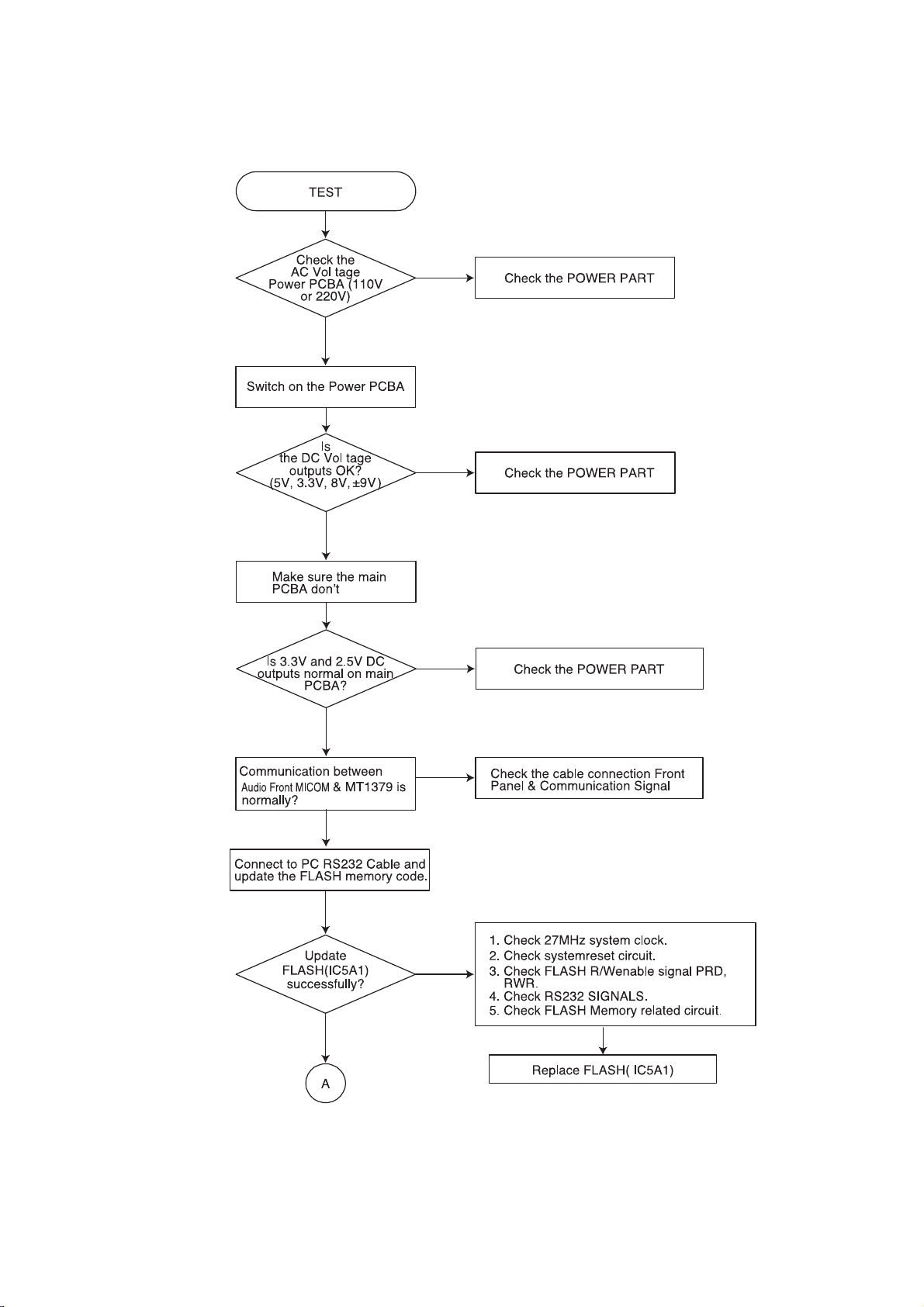
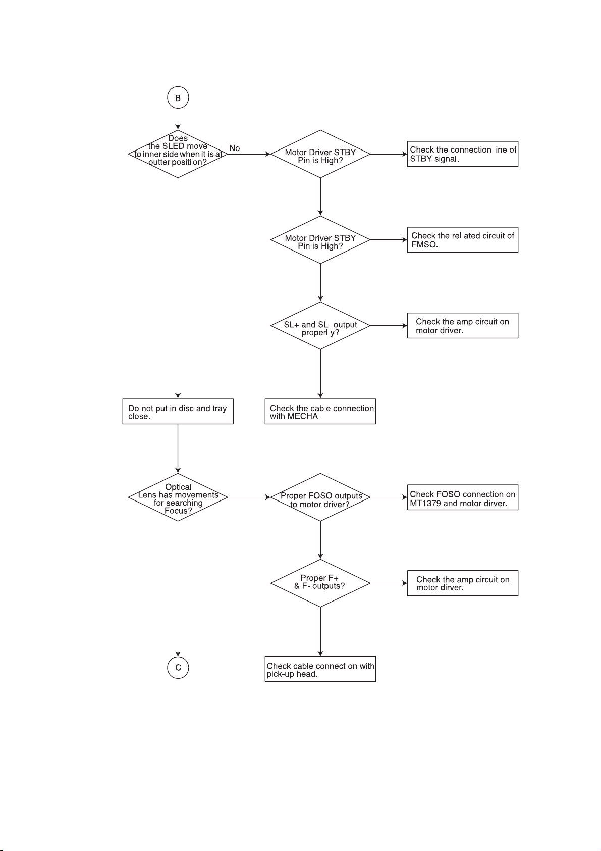
2. TEST & DEBUG FLOW
HCD-SB100/SB200
Ver. 1.1
NO
YES
NO
YES
YES
NO
NO
NO
YES
23

HCD-SB100/SB200
Ver. 1.1
NONO
YESYES
NO
YES
NO
YES
YES
NO
YES
NONO
YES
NO
YES
NO
24
YES
NO
HCD-SB100/SB200
Ver. 1.1
YES
YES
NO
YES
NO
YES
YES
NO
YES
NO
YES
25

HCD-SB100/SB200
Ver. 1.1
NONO
YES
YES
YES
NO
NO
YES
NO
YES
NO
YES
YES
NO
NO
YES
NO
YES
26
 Loading...