

Sony DCR-TRV15E, DCR-TRV17E Service Manual
DCR-TRV15E/TRV17E
RMT-814
SERVICE MANUAL
SERVICE MANUALSERVICE MANUAL
Level 1
Ver 1.0 2001. 04
Photo : DCR-TRV17E
RMT-814
SPECIFICATIONS
Video camera
recorder
System
Video recording system
2 rotary heads
Helical scanning system
Audio recording system
Rotary heads, PCM system
Quantization: 12 bits (Fs 32 kHz,
stereo 1, stereo 2), 16 bits
(Fs 48 kHz, stereo)
Video signal
PAL colour, CCIR standards
Usable cassette
Mini DV cassette with the
mark printed
Tape speed
SP: Approx. 18.81 mm/s
LP: Approx. 12.56 mm/s
Recording/playback time (using
cassette DVM60)
SP: 1 hour
LP: 1.5 hours
Fastforward/rewind time
(using cassette DVM60)
Approx. 2 min. and 30 seconds
Viewfinder
Electric viewfinder (colour)
Image device
4.5 mm (1/4 type) CCD (Charge
Coupled Device)
Approx. 800 000 pixels
(Effective: Approx. 400 000
pixels)
Lens
Carl Zeiss
Combined power zoom lens
Filter diameter
30 mm (1 3/16 in.)
10× (Optical), 120× (Digital)
Focal length
3.3 - 33 mm (5/32 - 1 5/16 in.)
When converted to a 35 mm still
camera
Camera/Memory (DCR-TRV17E
only) mode:
42 - 420 mm (1 11/16 - 16 5/8 in.)
Colour temperature
Auto, HOLD (Hold),
(3 200 K),
Minimum illumination
5 lx (lux) (F 1.7)
0 lx (lux) (in the NightShot
mode)*
* Objects unable to be seen due
to the dark can be shot with
infrared lighting.
Output connectors
S video output
4-pin mini DIN
Luminance signal: 1 Vp-p, 75 Ω
(ohms), unbalanced
Chrominance signal: 0.3 Vp-p,
75 Ω (ohms)
Outdoor (5 800 K)
Indoor
Audio/Video output
AV MINI JACK, 1 Vp-p, 75 Ω
(ohms), unbalanced, sync
negative
327 mV, (at output impedance
more than 47 kΩ (kilohms))
Output impedance with less than
2.2 kΩ (kilohms)/Stereo minijack
(ø 3.5mm)
DV output
4-pin connector
Headphone jack
Stereo minijack (ø 3.5 mm)
USB jack (DCR-TRV17E only)
mini-B
LANC
Special mini-minijack (ø 2.5 mm)
MIC jack
Stereo minijack (ø 3.5 mm)
LCD screen
Picture
DCR-TRV15E:
6.2 cm (2.5 type)
50.3 × 37.4 mm (2 × 1 1/2 in.)
DCR-TRV17E:
8.8 cm (3.5 type)
72.4 × 50.4 mm (2 7/8 × 2 in.)
Total dot number
123 200 (560 × 220)
jack
AEP Model
UK Model
J MECHANISM
General
Power requirements
7.2 V (battery pack)
8.4 V (AC power adaptor)
Average power consumption
(when using the battery pack)
During camera recording using
LCD
DCR-TRV15E: 3.3 W
DCR-TRV17E: 3.7 W
Viewfinder
DCR-TRV15E: 2.5 W
DCR-TRV17E: 2.6 W
Operating temperature
0 °C to 40 °C (32 °F to 104 °F)
Storage temperature
–20 °C to +60 °C
(–4 °F to +140 °F)
Dimensions (Approx.)
74 × 95 × 175 mm
(2 7/8 × 3 3/4 × 6 1/2 in.) (w/h/
d)
Mass (approx.)
DCR-TRV15E: 610 g (1 lb 5 oz)
DCR-TRV17E: 650 g (1 lb 6 oz)
main unit only
DCR-TRV15E: 700 g (1 lb 8 oz)
DCR-TRV17E: 740 g (1 lb 10 oz)
including the battery pack
NP-FM30, cassette DVM60, lens
cap
Supplied accessories
See page 3.
— Continued on next page —
DIGITAL VIDEO CAMERA RECORDER

AC power adaptor
Power requirements
100 - 240 V AC, 50/60 Hz
Power consumption
23 W
Output voltage
DC OUT: 8.4 V, 1.5 A in the
operating mode
Operating temperature
0 °C to 40 °C (32 °F to 104 °F)
Storage temperature
–20 °C to +60 °C (–4 °F to +140
°F)
Dimensions (approx.)
125 × 39 × 62 mm
(5 × 1 9/16 × 2 1/2 in.) (w/h/d)
excluding projecting parts
Mass (approx.)
280 g (9.8 oz)
excluding mains lead
Cord length (approx.)
Mains lead: 2 m (6.6 feet)
Connecting cord: 1.6 m (5.2 feet)
Battery pack
Maximum output voltage
DC 8.4 V
Output voltage
DC 7.2 V
Capacity
5.0 Wh (700 mAh)
Dimensions (approx.)
38.2 × 20.5 × 55.6 mm
(1 9/16 × 13/16 × 2 1/4 in.)
(w/h/d)
Mass (approx.)
65 g (2.7 oz)
Type
Lithium ion
“Memory Stick”
(DCR-TRV17E only)
Memory
Flash memory
4MB: MSA-4A
Operating voltage
2.7-3.6V
Power consumption
Approx. 45mA in the operating
mode
Approx. 130µA in the standby
mode
Dimensions (approx.)
50 × 2.8 × 21.5 mm
(2 × 1/8 × 7/8 in.) (w/h/d)
Mass (approx.)
4 g (0.14 oz)
Design and specifications are
subject to change without notice.
SAFETY-RELATED COMPONENT WARNING!!
COMPONENTS IDENTIFIED BY MARK 0 OR DOTTED LINE WITH
MARK 0 ON THE SCHEMATIC DIAGRAMS AND IN THE PARTS
LIST ARE CRITICAL TO SAFE OPERATION. REPLACE THESE
COMPONENTS WITH SONY PARTS WHOSE PART NUMBERS
APPEAR AS SHOWN IN THIS MANUAL OR IN SUPPLEMENTS
PUBLISHED BY SONY.
SAFETY CHECK-OUT
After correcting the original service problem, perform the following
safety checks before releasing the set to the customer.
1. Check the area of your repair for unsoldered or poorly-soldered
connections. Check the entire board surface for solder splashes
and bridges.
2. Check the interboard wiring to ensure that no wires are
"pinched" or contact high-wattage resistors.
3. Look for unauthorized replacement parts, particularly
transistors, that were installed during a previous repair . Point
them out to the customer and recommend their replacement.
4. Look for parts which, through functioning, show obvious signs
of deterioration. Point them out to the customer and
recommend their replacement.
5. Check the B+ voltage to see it is at the values specified.
6. Flexible Circuit Board Repairing
• Keep the temperature of the soldering iron around 270˚C
during repairing.
• Do not touch the soldering iron on the same conductor of the
circuit board (within 3 times).
• Be careful not to apply force on the conductor when soldering
or unsoldering.
— 2 —
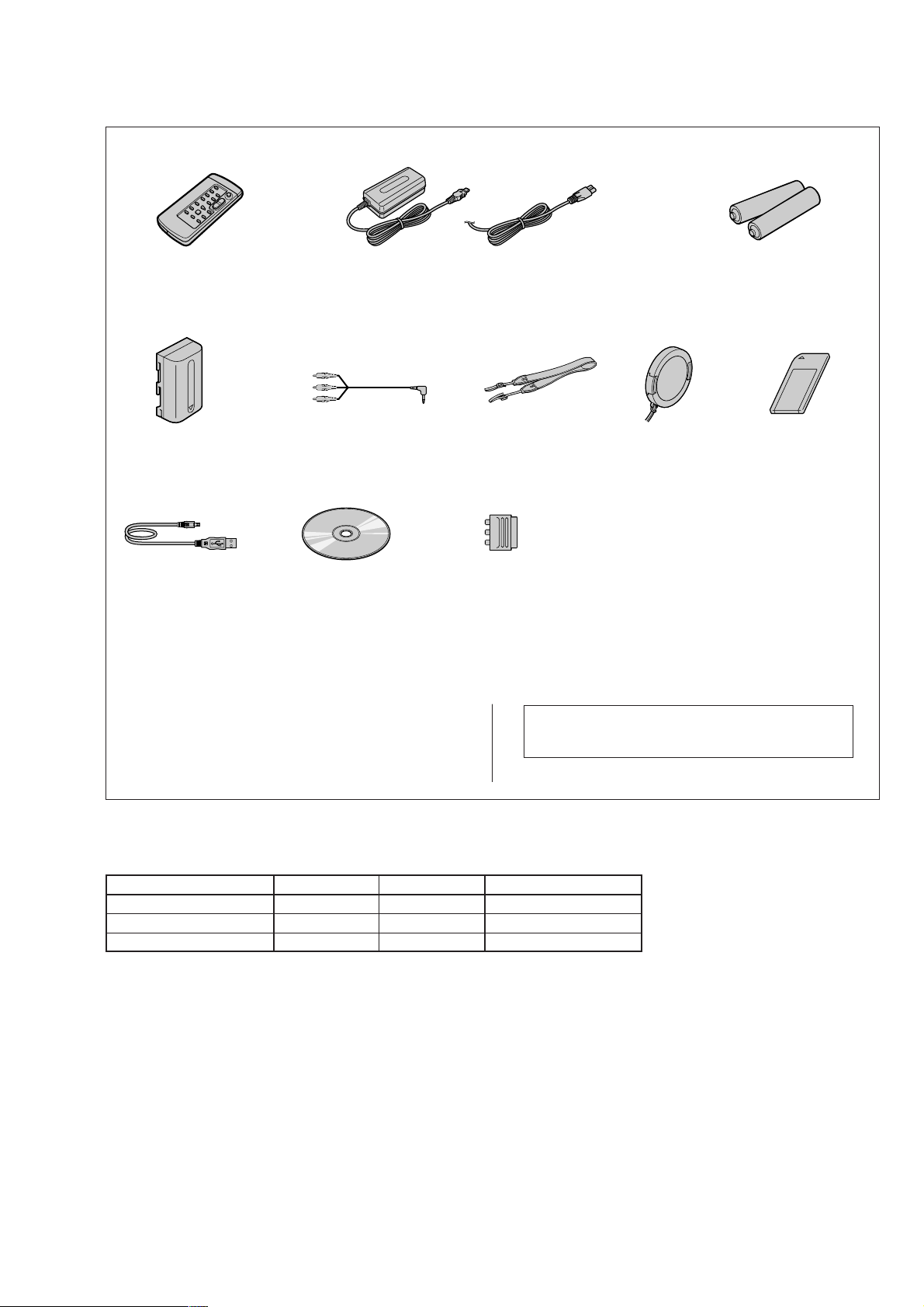
Checking supplied accessories.
Make sure that the following accessories are supplied with your camcorder.
Wireless Remote Commander (1)
RMT-814
1-475-141-61
NP-FM30 battery pack (1)
(not supplied)
USB cable (1)
1-757-293-21
(DCR-TRV17E only)
CD-ROM
(SPVD-004 USB Driver)(1)
3-066-676-01
(DCR-TRV17E only)
AC power adaptor (1)
(AC-L10A)
0
1-475-599-11
A/V connecting cable (1.5m) (1)
1-765-080-11
Other accessories
3-067-426-11 MANUAL, INSTRUCTION (ENGLISH/RUSSIAN)
3-067-426-21 MANUAL, INSTRUCTION (FRENCH/GERMAN)(AEP)
3-067-426-31 MANUAL, INSTRUCTION (ENGLISH/DUTCH)(AEP)
3-067-426-41 MANUAL, INSTRUCTION (SPANISH/PORTUGUESE)(AEP)
3-067-426-51 MANUAL, INSTRUCTION (ITALIAN/GREEK)(AEP)
Power cord (Main lead)(1) (AEP model)
0
1-575-131-11
Power cord (Main lead)(1) (UK model)
0
1-783-374-11
Shoulder strap (1)
3-987-015-01
21-pin adaptor (1)
1-573-291-11
Note : The components identified by mark 0 or dotted
line with mark 0 are critical for safety.
Replace only with part number specified.
Lens cap (1)
X-3950-537-1
Size AA (R6) battery for
Remote Commander (2)
(not supplied)
Memory Stick (1)
(MSA-4A)
A-7033-740-A
(DCR-TRV17E only)
Table for difference of functions
Model
LCD size
DCR-TRV15E
2.5 inch
Memory stick
DIGITAL IN/OUT (USB)
DCR-TRV17E
Remark
3.5 inch
✕
✕
a
a
a: with MS-070 board
a: with MS-070 board
— 3 —

TABLE OF CONTENTS
SERVICE NOTE
1. POWER SUPPLY DURING REPAIRS ····························· 5
2. TO TAKE OUT A CASSETTE WHEN NOT EJECT
(FORCE EJECT) ································································5
SELF-DIAGNOSIS FUNCTION
1. SELF-DIAGNOSIS FUNCTION·······································6
2. SELF-DIAGNOSIS DISPLAY ·········································· 6
3. SERVICE MODE DISPLAY ············································· 6
3-1. Display Method ·································································· 6
3-2. Switching of Backup No. ··················································· 6
3-3. End of Display···································································· 6
4. SELF-DIAGNOSIS CODE TABLE··································· 7
1. MAIN PARTS
1. ORNAMENTAL PARTS···················································· 8
2. DISASSEMBLY································································· 9
2-1. LCD SECTION (PD-143 BOARD) ·································10
2-2. EVF SECTION (LB-069 BOARD)··································10
2-3.
FRONT PANEL SECTION (MA-403, FB-218 BOARDS) ·
2-4. CABINET (R) SECTION (CK-101 BOARD)················· 11
2-5. BT PANEL SECTION, EVF SECTION ·························· 12
2-6. MAIN CHASSIS COMPLATE SECTION ······················12
2-7. LENS SECTION ······························································ 12
2-8. JK-204 BOARD ······························································· 13
2-9. VC-260 BOARD, MS-070 BOARD (TRV17E),
MECHANISM DECK······················································ 13
2-10. CONTROL SWITCH BLOCK (PS-1700) ······················· 14
2-11. HINGE ASSEMBLY ························································ 14
2-12. GRIP BELT ······································································ 15
3. REPAIR PARTS LIST ······················································ 16
3-1. EXPLODED VIEWS ······················································· 16
3-1-1.OVERALL SECTION ······················································ 16
3-1-2.CABINET (R) SECTION ················································ 17
3-1-3.LCD SECTION ································································ 18
3-1-4.CABINET (L) SECTION·················································19
3-1-5.MAIN CHASSIS COMPLETE SECTION······················ 20
3-1-6.EVF SECTION·································································21
11
2. GENERAL
Main Features ············································································· 22
Checking supplied accessories ··················································· 22
Quick Start Guide ·······································································22
Getting started
Using this manual ··································································· 23
Step 1 Preparing the power supply ········································· 23
Installing the battery pack···················································· 23
Charging the battery pack ···················································· 24
Connecting to the wall socket·············································· 25
Step 2 Setting the date and time ············································· 25
Step 3 Inserting a cassette······················································· 26
Recording – Basics
Recording a picture································································· 26
Shooting backlit subjects – BACK LIGHT ···························· 28
Shooting in the dark – Night Shot/Super NightShot ·············· 28
Self-timer recording································································ 28
Checking the recording – END SEARCH/EDITSEARCH/
Rec Review ·········································································· 29
Playback – Basics
Playing back a tape ································································· 29
Viewing the recording on TV ················································· 31
Advanced Recording Operations
Recording a still image on a tape – Tape Photo recording
Adjusting the white balance manually···································· 32
Using the wide mode ······························································ 33
Using the fader function ························································· 33
Using special effects – Picture effect······································ 34
········ 31
Using special effects – Digital effect······································ 34
Using the PROGRAM AE function ········································35
Adjusting the exposure manually ··········································· 36
Focusing manually·································································· 36
Interval recording····································································36
Frame by frame recording – Cut recording ···························· 37
Advanced Playback Operations
Playing back a tape with picture effects ································· 38
Playing back a tape with digital effects ·································· 38
Enlarging images recorded on tapes – Tape PB ZOOM ········· 38
Quickly locating a scene using the zero set memory function
Searching the boundaries of recorded tape by title
– Title search········································································ 39
Searching a recording by date – Date search·························· 39
Searching for a photo – Photo search/Photo scan··················· 40
Editing
Dubbing a tape ········································································ 41
Dubbing only desired scenes – Digital program editing ········ 42
Audio dubbing ········································································ 45
Superimposing a title ······························································ 46
Making your own titles ··························································· 47
Labelling a cassette································································· 47
Customizing Y our Camcorder
Changing the menu settings···················································· 48
“Memory Stick” Operations (DCR-TRV17E only)
Using a “Memory Stick” – introduction ································· 50
Recording still images on “Memory Stick”s
– Memory photo recording ·················································· 52
Recording an image from a tape as a still image ····················54
Recording moving pictures on “Memory Stick”s
– MPEG movie recording ···················································· 54
Recording a picture from a tape as a moving picture ············· 55
Superimposing a still picture in a “Memory Stick”
on a moving picture – MEMORY MIX ·······························55
Copying still images from a tape – Photo save·······················56
Viewing a still picture – Memory photo playback ·················· 57
Viewing a moving picture – MPEG movie playback ············· 58
Viewing images using computer ·············································58
Enlarging still images recorded on “Memory Stick”s
– Memory PB ZOOM ·························································· 60
Playing back images in a continuous loop – SLIDE SHOW
Preventing accidental erasure – Image protection ··················61
Deleting images ······································································ 62
Writing a print mark – PRINT MARK··································· 62
Using the printer (optional) ···················································· 63
Troubleshooting
Types of trouble and their solutions ········································ 63
Self-diagnosis display ····························································· 65
Warning indicators and messages ··········································· 65
Additional Information
Usable cassettes ······································································ 66
About the “InfoLITHIUM” battery pack································ 66
About i.LINK·········································································· 67
Using your camcorder abroad················································· 67
Maintenance information and precautions······························68
Quick Reference
Identifying the parts and controls ··········································· 69
······· 61
····· 39
— 4 —

SERVICE NOTE
1. POWER SUPPLY DURING REPAIRS
In this unit, about 10 seconds after power is supplied to the battery terminal using the regulated power supply (8.4V), the po wer is shut of f so
that the unit cannot operate.
This following two methods are available to prevent this. Take note of which to use during repairs.
Method 1.
Use the AC power adaptor (AC-L10, AC-VQ800 etc.).
Method 2.
Connect the servicing remote commander RM-95 (J-6082-053-B) to the LANC jack, and set the commander switch to the “ADJ” side.
2. TO TAKE OUT A CASSETTE WHEN NOT EJECT (FORCE EJECT)
1 Refer to 2-3 to remove the top cabinet assembly.
2 Refer to 2-3 to remove the front panel assembly.
3 Refer to 2-4 to remove the cabinet (R) assembly.
4 Refer to 2-5 to remove the battery panel section.
5 Open the VC-260 board.
6 Disconnect CN007 (27P, 0.3mm) of VC-260 board.
7 Open the cassette lid.
8 Supply +4.5V from the DC power supply to the loading motor and unload with a pressing the cassette compartment.
Loading motor
VC-260 board
CN007
DC power supply
(+4.5Vdc)
— 5 —
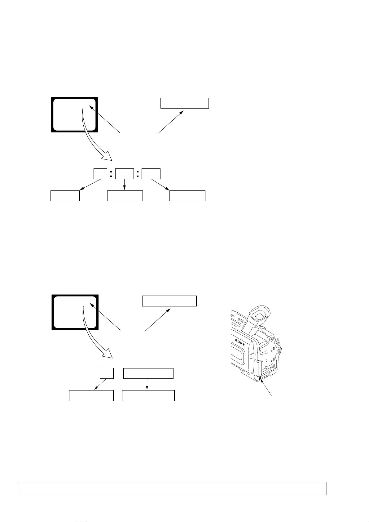
SELF-DIAGNOSIS FUNCTION
1. SELF-DIAGNOSIS FUNCTION
When problems occur while the unit is operating, the self-diagnosis
function starts working, and displays on the viewfinder , LCD screen
or LCD window what to do. This function consists of two display;
self-diagnosis display and service mode display.
Details of the self-diagnosis functions are provided in the Instruction
manual.
Viewfinder or LCD screen LCD window
C : 3 1 : 1 1
Blinks at 3.2Hz
1 1
Repaired by:
C : Corrected by customer
H : Corrected by dealer
E : Corrected by service
engineer
C
Indicates the appropriate
step to be taken.
E.g.
31 ....Reload the tape.
32 ....Turn on power again.
3 1
Block
2. SELF-DIAGNOSIS DISPLAY
When problems occur while the unit is operating, the counter of the
viewfinder, LCD screen or LCD window consists of an alphabet
and 4-digit numbers, which blinks at 3.2 Hz. This 5-character display
indicates the “repaired by:”, “block” in which the problem occurred,
and “detailed code” of the problem.
C : 3 1 : 11
Detailed Code
Refer to page 7.
Self-diagnosis Code Table.
3. SER VICE MODE DISPLAY
The service mode display shows up to six self-diagnosis codes shown in the past.
3-1. Display Method
While pressing the “STOP” key, set the switch from OFF to “PLAYER”, and continue pressing the “STOP” key for 5 seconds continuously.
The service mode will be displayed, and the counter will show the backup No. and the 5-character self-diagnosis codes.
Viewfinder or LCD screen
[3] C : 3 1 : 1 1
Lights up
[3]
Backup No.
Order of previous errors
C : 3 1 : 1 1
Self-diagnosis Codes
3-2. Switching of Backup No.
By rotating the control dial, past self-diagnosis codes will be shown in order. The backup No. in the [] indicates the order in which the
problem occurred. (If the number of problems which occurred is less than 6, only the number of problems which occurred will be shown.)
[1] : Occurred first time [4] : Occurred fourth time
[2] : Occurred second time [5] : Occurred fifth time
[3] : Occurred third time [6] : Occurred the last time
LCD window
3 C : 3 1 : 11
Control dial
3-3. End of Display
Turning OFF the power supply will end the service mode display.
Note: The “self-diagnosis display” data will be backed up by the coin-type lithium battery of CK-101 board BT8301. When the cabinet (R) (CK-101
board) is removed, the “self-diagnosis display” data will be lost by initialization.
— 6 —

4. SELF-DIAGNOSIS CODE TABLE
Self-diagnosis Code
Function
Repaired by:
C
C
C
C
C
C
C
C
C
C
C
C
C
C
C
C
C
C
C
C
C
C
C
E
E
E
E
Block
04
21
22
31
31
31
31
31
31
31
31
31
31
31
31
32
32
32
32
32
32
32
32
61
61
62
62
Detailed
Code
00
00
00
10
11
20
21
22
23
24
30
40
42
10
11
20
21
22
23
24
30
40
42
00
10
00
01
Symptom/State
Non-standard battery is used.
Condensation.
Video head is dirty.
LOAD direction. Loading does not
complete within specified time
UNLOAD direction. Loading does not
complete within specified time
T reel side tape slacking when unloading
Winding S reel fault when counting the
rest of tape.
T reel fault.
S reel fault.
T reel fault.
FG fault when starting capstan.
FG fault when starting drum.
FG fault during normal drum operations.
LOAD direction loading motor time-
out.
UNLOAD direction loading motor
time-out.
T reel side tape slacking when
unloading.
Winding S reel fault when counting the
rest of tape.
T reel fault.
S reel fault.
T reel fault.
FG fault when starting capstan.
FG fault when starting drum
FG fault during normal drum
operations
Difficult to adjust focus
(Cannot initialize focus.)
Zoom operations fault
(Cannot initialize zoom lens.)
Steadyshot function does not work well.
(With pitch angular velocity sensor output
stopped.)
Steadyshot function does not work well.
(With yaw angular v elocity sensor output
stopped.)
Correction
Use the info LITHIUM battery.
Remove the cassette, and insert it again after one hour.
Clean with the optional cleaning cassette.
Load the tape again, and perform operations from the beginning.
Load the tape again, and perform operations from the beginning.
.
Load the tape again, and perform operations from the beginning.
Load the tape again, and perform operations from the beginning.
Load the tape again, and perform operations from the beginning.
Load the tape again, and perform operations from the beginning.
Load the tape again, and perform operations from the beginning.
Load the tape again, and perform operations from the beginning.
Load the tape again, and perform operations from the beginning.
Load the tape again, and perform operations from the beginning.
Remove the battery or power cable, connect, and perform
operations from the beginning.
Remove the battery or power cable, connect, and perform
operations from the beginning.
Remove the battery or power cable, connect, and perform
operations from the beginning.
Remove the battery or power cable, connect, and perform
operations from the beginning.
Remove the battery or power cable, connect, and perform
operations from the beginning.
Remove the battery or power cable, connect, and perform
operations from the beginning.
Remove the battery or power cable, connect, and perform
operations from the beginning.
Remove the battery or power cable, connect, and perform
operations from the beginning.
Remove the battery or power cable, connect, and perform
operations from the beginning.
Remove the battery or power cable, connect, and perform
operations from the beginning.
Inspect the lens block focus reset sensor (Pin 7 of CN004 of VC-
260 board) when focusing is performed when the focus ring is rotated
in the focus manual mode, and the focus motor drive circuit (IC204
of VC-260 board) when the focusing is not performed.
Inspect the lens block zoom reset sensor (
260 board
operated and the zoom motor drive circuit (IC204 of VC-260 board)
when zooming is not performed.
Inspect pitch angular velocity sensor (SE3102 of JK-204 board)
peripheral circuits.
Inspect yaw angular velocity sensor (SE3101 of JK-204 board)
peripheral circuits.
) when zooming is performed when the zoom lens is
Pin qh of CN004 of VC-
— 7 —
DCR-TRV15E/TRV17E
1. MAIN PARTS
Note:
• Follow the disassembly procedure in the numerical order given.
• Items marked “*” are not stocked since they are seldom required for routine service.
Some delay should be anticipated when ordering these items.
• The parts numbers of such as a cabinet are also appeared in this section.
Refer to the parts number mentioned below the name of parts to order.
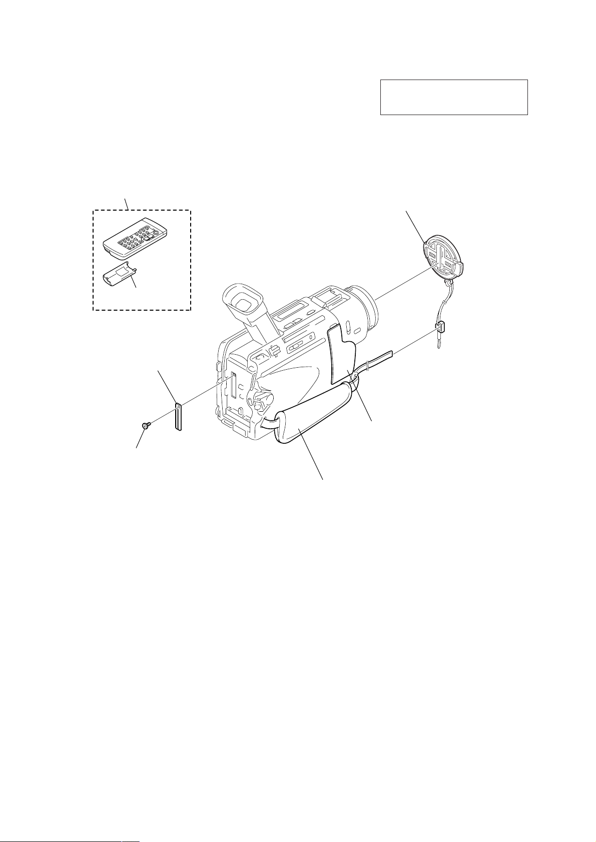
1. ORNAMENTAL PARTS
Remote commander (RMT-814)
1-475-141-61
Battery case lid
3-742-854-01
The components identified by mark 0 or
dotted line with mark 0 are critical for safety.
Replace only with part number specified.
Lens cap assembly
X-3950-537-1
CPC lid
3-067-025-01
Screw (M1.7 × 4),
lock ace, p2
3-989-735-81
Jack cover
3-066-839-01
Note: Disassembling the main unit
is necessary to replace it.
Grip belt
Note: Disassembling the main unit
is necessary to replace it.
— 8 —
2. DISASSEMBLY
DCR-TRV15E/TRV17E
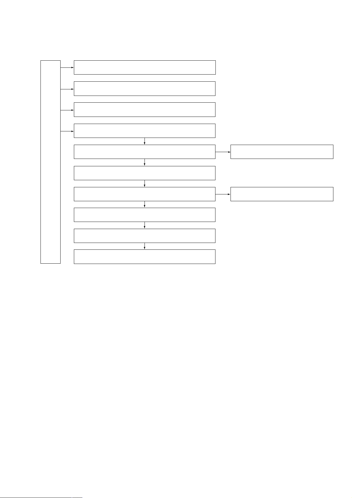
2-1. LCD section (PD-143 board)
2-2. EVF section (LB-069 board)
2-12. Grip belt
2-3. Front panel section (MA-403, FB-218 boards)
2-4. Cabinet (R) section (CK-101 board)
2-5. BT panel section, EVF section
2-7. Lens section
2-6. Main chassis complete section
2-9. VC-260 board,
MS-070 board (TRV17E), Mechanism deck
2-8. JK-204 board
2-11. Hinge assembly
2-10. Control switch block (PS-1700)
The following flow chart shows the disassembly procedure.
— 9 —
NOTE: F ollo w the disassembly procedure in the numerical order given.
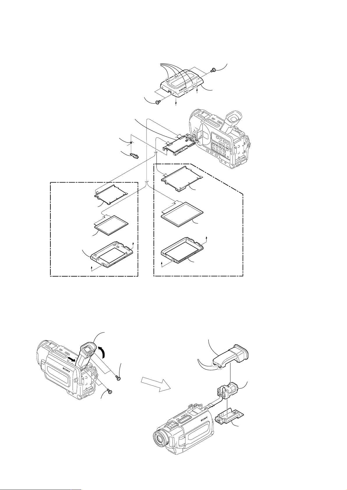
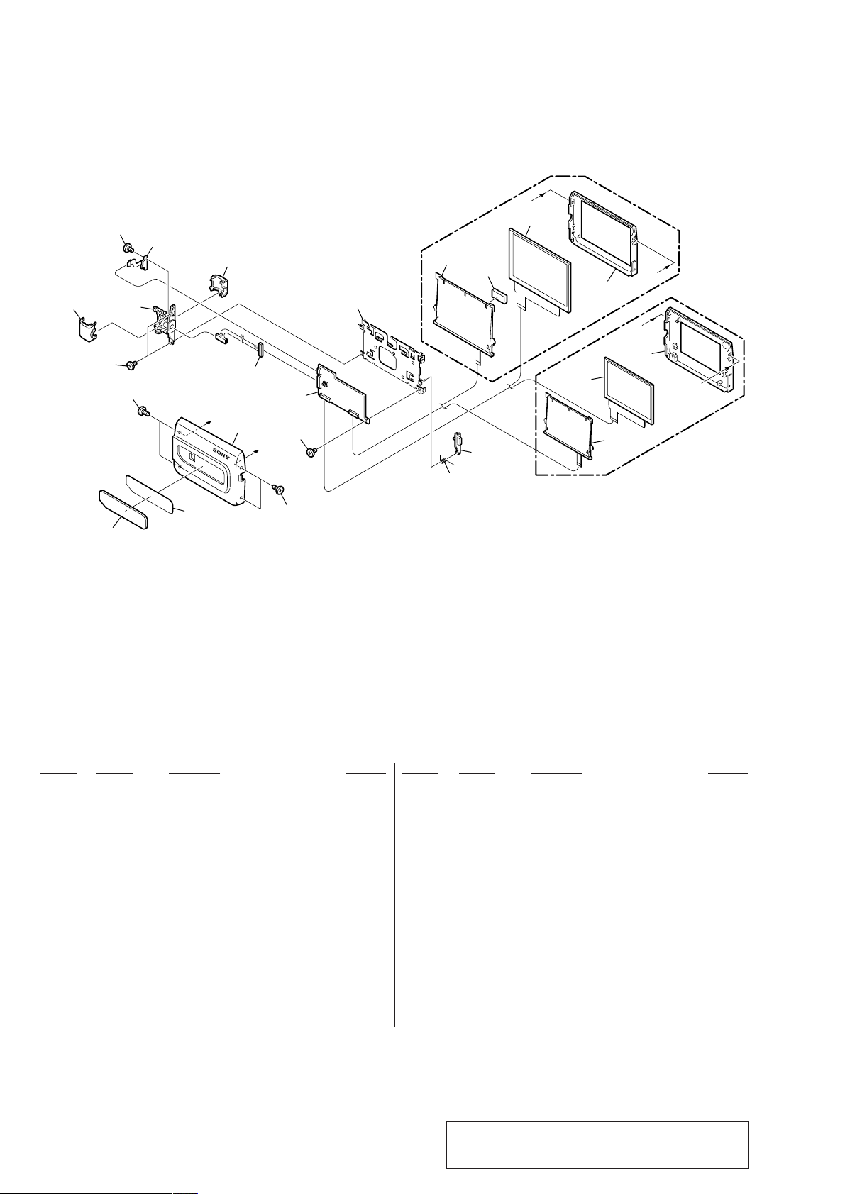
2-1. LCD SECTION (PD-143 BOARD)
3 Four claws
1 Two screws
(M2 × 4),
lock ace, p2
q; PD-143 board,
P frame assembly (3.5) (TRV17E),
P frame assembly (2.5) (TRV15E)
7 Torsion spring (P)
A
2 Two screws
(M2 × 4),
lock ace, p2
4 P cabinet (C) assembly
B
6 Panel open button
(TRV15E)
9 Back light
8 Liquid crystal
indicator module
5 P cabinet (M)
(2.5)
A
2-2. EVF SECTION (LB-069 BOARD)
B
(TRV17E)
A
PD-143
9 Back light,
BL sheet
8 Liquid crystal
indicator module
B
5 P cabinet (M)
(3.5)
B
1 Raise the EVF in the A direction and
slide it in the B direction.
A
3 Two tapping screws
(M1.7 × 5)
2 Two tapping screws
(M1.7 × 5)
— 10 —
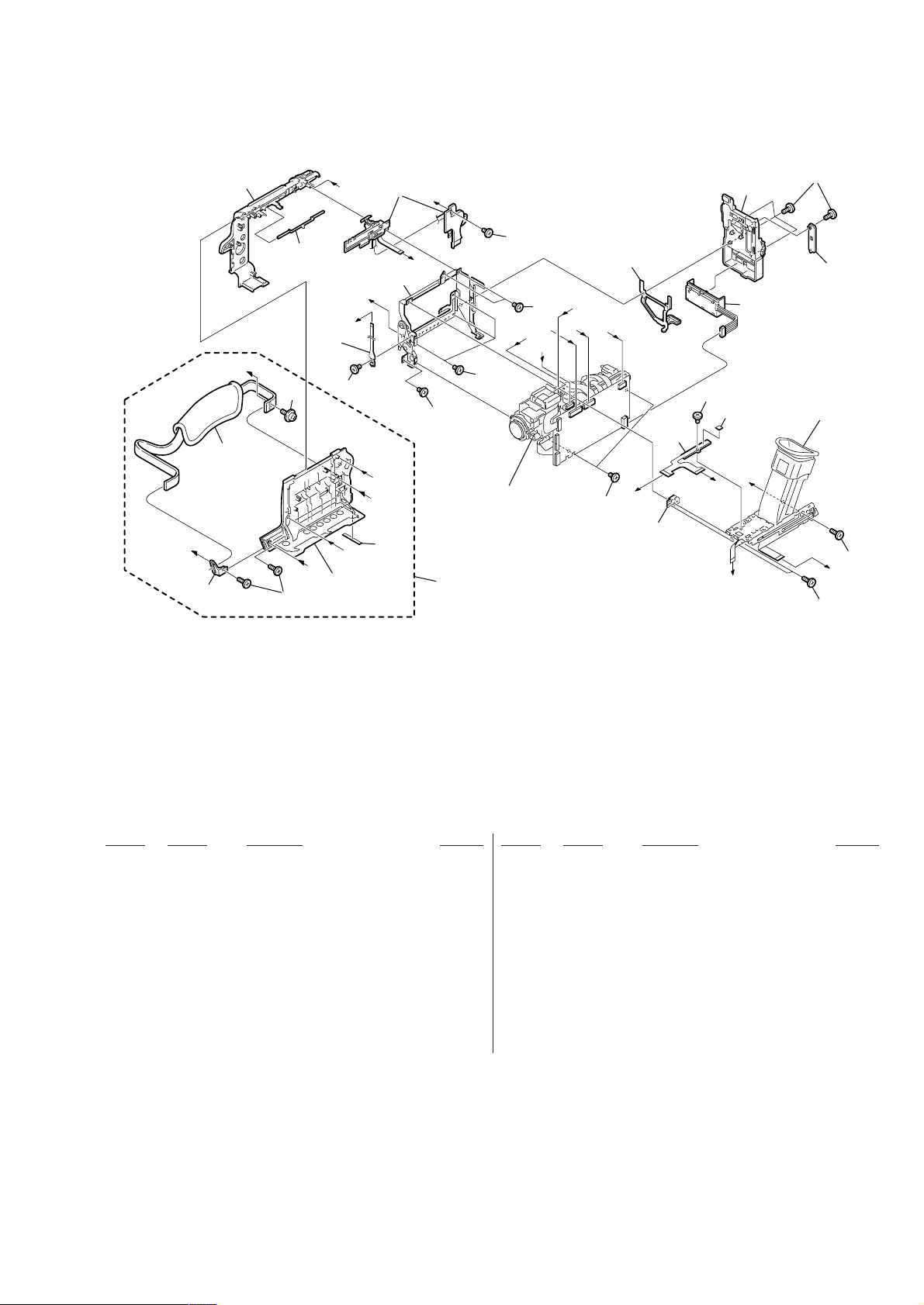
2 VF cabinet (upper)
assembly
1Two claws
4 VF lens assembly
3 VF cabinet (lower)
assembly
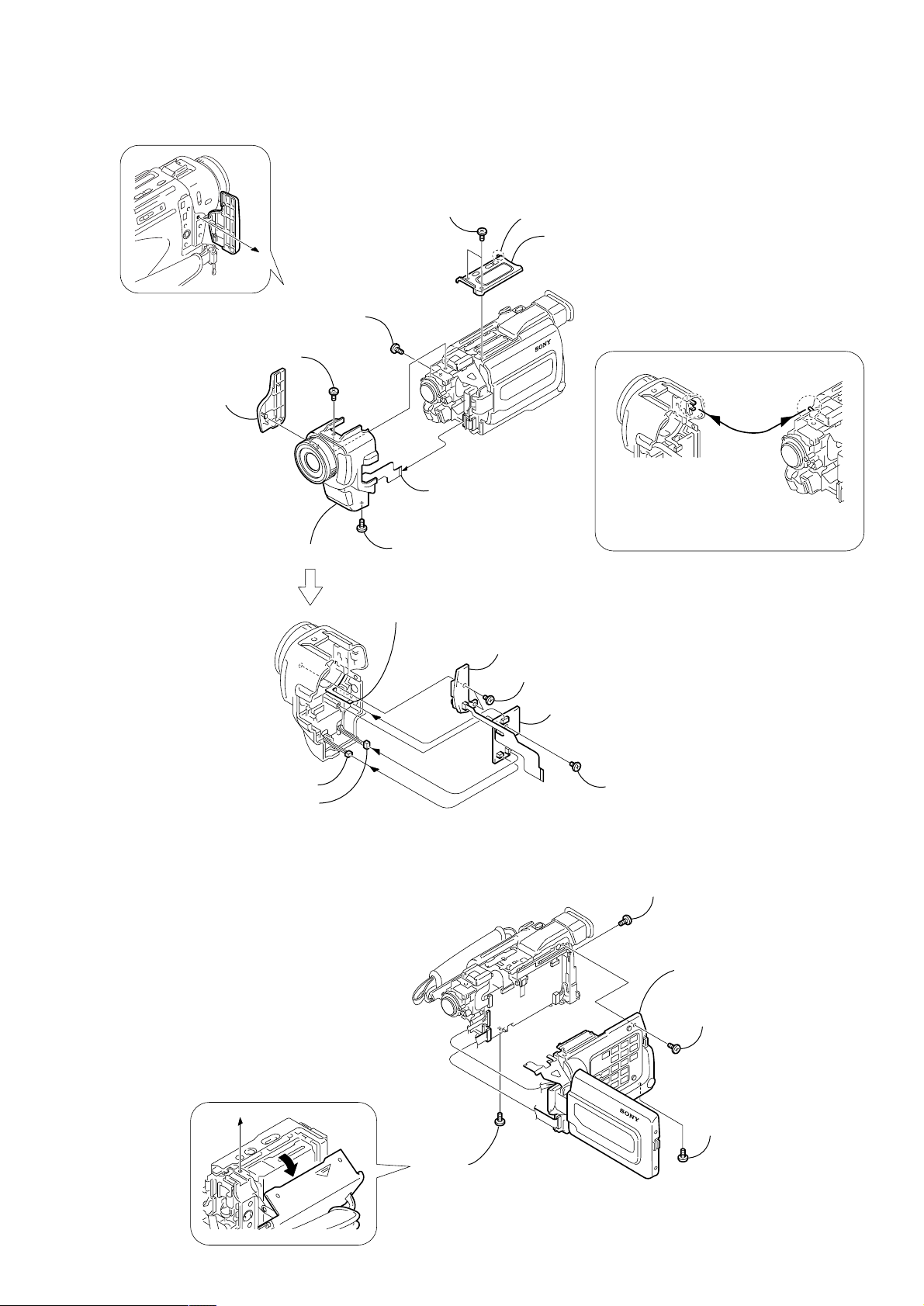
2-3. FRONT PANEL SECTION (MA-403, FB-218 BOARDS)
1 Two screws
(M1.7 × 4),
lock ace, p2
4 Screw
(M1.7 × 4),
lock ace, p2
6 Screw
(M1.7 × 4),
lock ace, p2
5 Screw
(M1.7 × 4),
lock ace, p2
3 TOP cabinet assembly
2 Claw
8 Jack cover
9 Front panel section
7 FP-304 flexible
board (24P)
1 FP-311 flexible
board (5P)
2 Microphone (2P)
3 Microphone (2P)
7 FB-218 board
5 MA-403 board
PRECAUTION DURING INSTALLATION
To attach the front panel, align the switch
position as shown.
6 Two tapping
screws (M1.7 × 3.5)
4 Tapping
screw (M1.7 × 3.5)
n
2-4. CABINET (R) SECTION (CK-101 BOARD)
4 Screw
(M1.7 × 4),
lock ace, p2
1 Screw
(M1.7 × 4),
lock ace, p2
5 Cabinet (R) sectio
VC-260
3 Screw
(M1.7 × 4),
lock ace, p2
2 Screw
(M1.7 × 4),
lock ace, p2
— 11 —
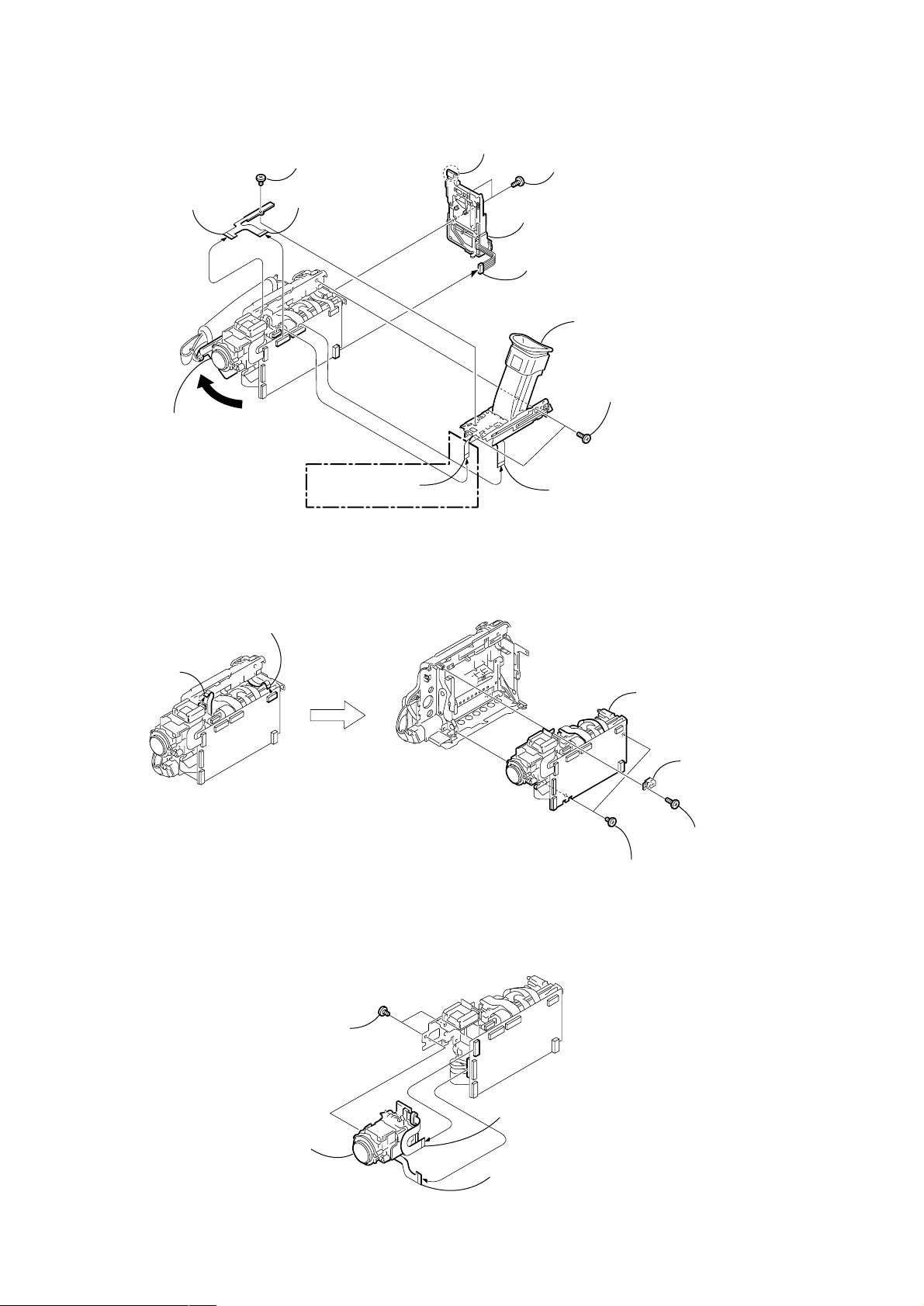
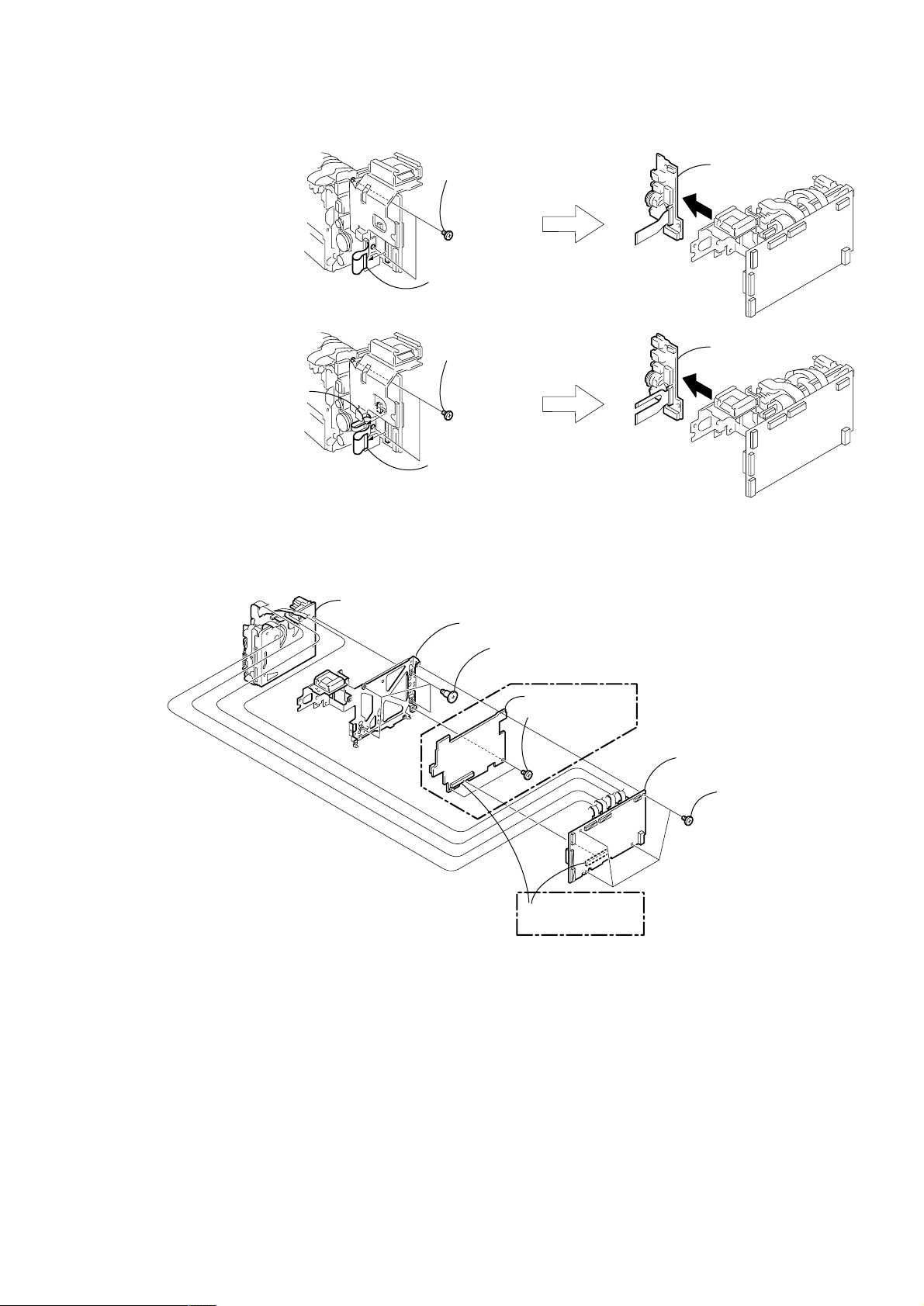
2-5. BT PANEL SECTION, EVF SECTION
)
6 Screw
8 FP-305 flexible
board (15P)
2 Open the
cassette lid
(M1.7 × 2.5), p
7 FP-305 flexible
board (24P)
-260
C
V
(TRV17E)
qa FP-313 flexible
board (10P)
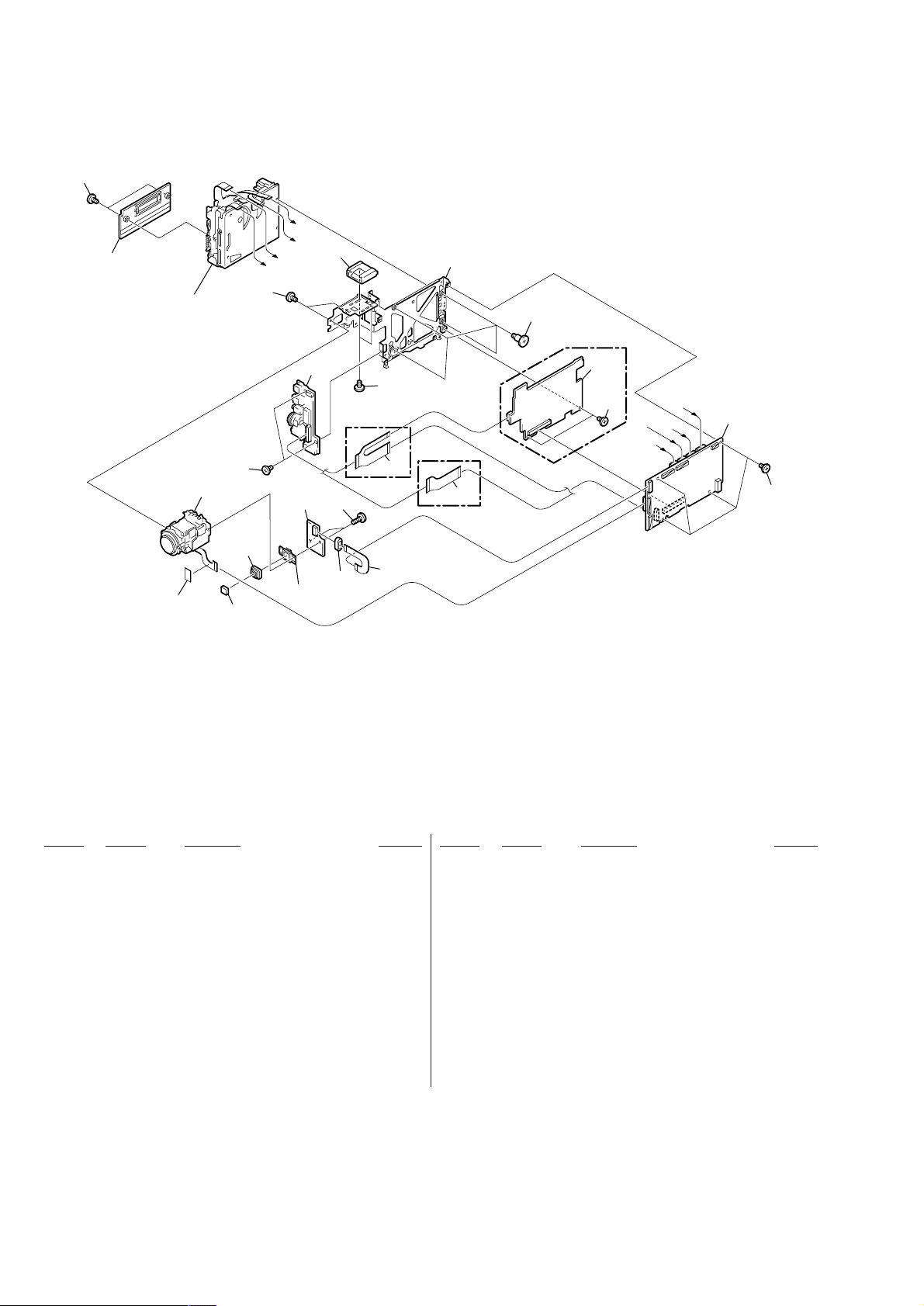
2-6. MAIN CHASSIS COMPLATE SECTION
3 Claw
5 BT panel section
4 Battery terminal
board (6P)
1 Two screw
(M1.7 × 4),
lock ace, p2
qs EVF section
9 Two tapping screws
(M1.7 × 5)
0 FP-320 flexible
board (20P)
2 Control switch block
(PS-1700) (10P)
1 FP-310 flexible
board (5P)
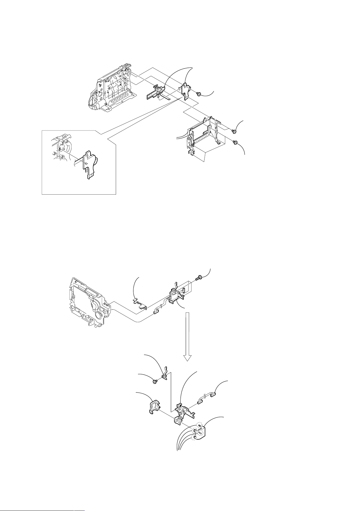
2-7. LENS SECTION
-260
C
V
1 Two tapping screws
(M1.7 × 3.5)
VC-260
6 Main chassis
complete section
4 M spacer
-260
C
V
3 Tapping screw
(M1.7 × 5)
5 Two screws
(M1.7 × 2.5), p
4 Lens section
2 FP-306 flexible
board (16P)
3 Flexible board
(From lens device) (24P
— 12 —
2-8. JK-204 BOARD
VC-260
VC-260
2 FP-307 flexible
board (7P)
1 FP-307 flexible
board (26P)
3 Two screws
(M1.7 × 2.5), p
4 JK-204 board
1 FP-314 flexible
board (26P)
[TRV17E MODEL]
[TRV15E MODEL]
3 JK-204 board
2 Two screws
(M1.7 × 2.5), p
P
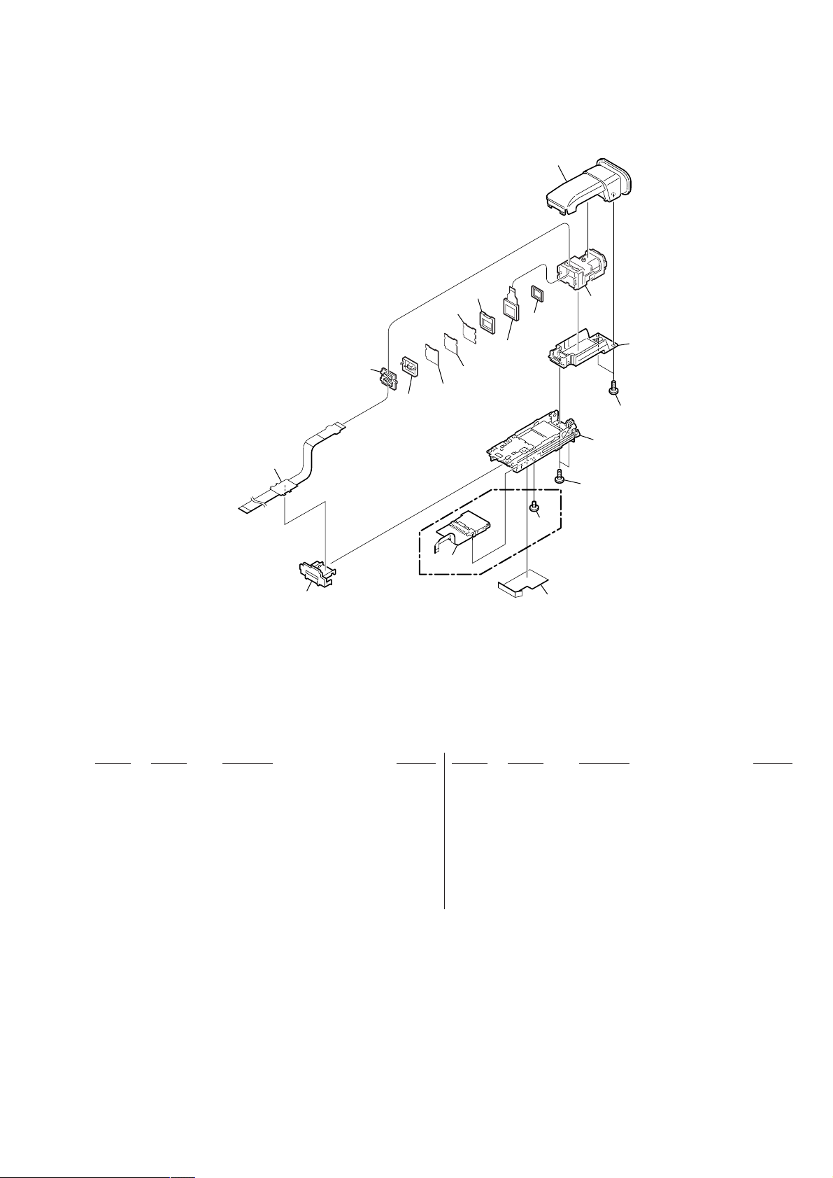
2-9. VC-260 BOARD, MS-070 BOARD (TRV17E), MECHANISM DECK
8 Mechanism deck
7 Main frame assembly
6 Four screws
(M1.4 × 1.5)
5 MS-070 board
4 Two screws
(M1.7 × 2.5), P
MS-070
2 Board to board
connector (100P)
(TRV17E)
(TRV17E)
3 VC-260 board
1 Four screws
(M1.7 × 2.5),
VC-260
— 13 —
2-10. CONTROL SWITCH BLOCK (PS-1700)
5 Control switch block
(PS-1700)
4 Tapping screw
(M1.7 × 3.5)
PRECAUTION DURING
INSTALLATION
3 CS frame assembly,
FP-310 flexible board
To attach, align the switch
position as shown.
2 Two tapping screws
(M1.7 × 3.5)
1 Four tapping screws
(M1.7 × 3.5)
2-11. HINGE ASSEMBLY
Remove the LCD unit referring to section “2-1. DISASSEMBLY” of Level 2 before starting the following disassembling
work.
1 Four screws
3 Hinge reinforcement
CK-101
(M2 × 6)
5 FP-309 flexible
board
4 Screw
(M1.7 × 2.5), P
3 Hinge cover (rear)
2
7 Hinge assembly
6 Harness (PV-130)
2 Hinge cover (front)
1 Four claws
— 14 —
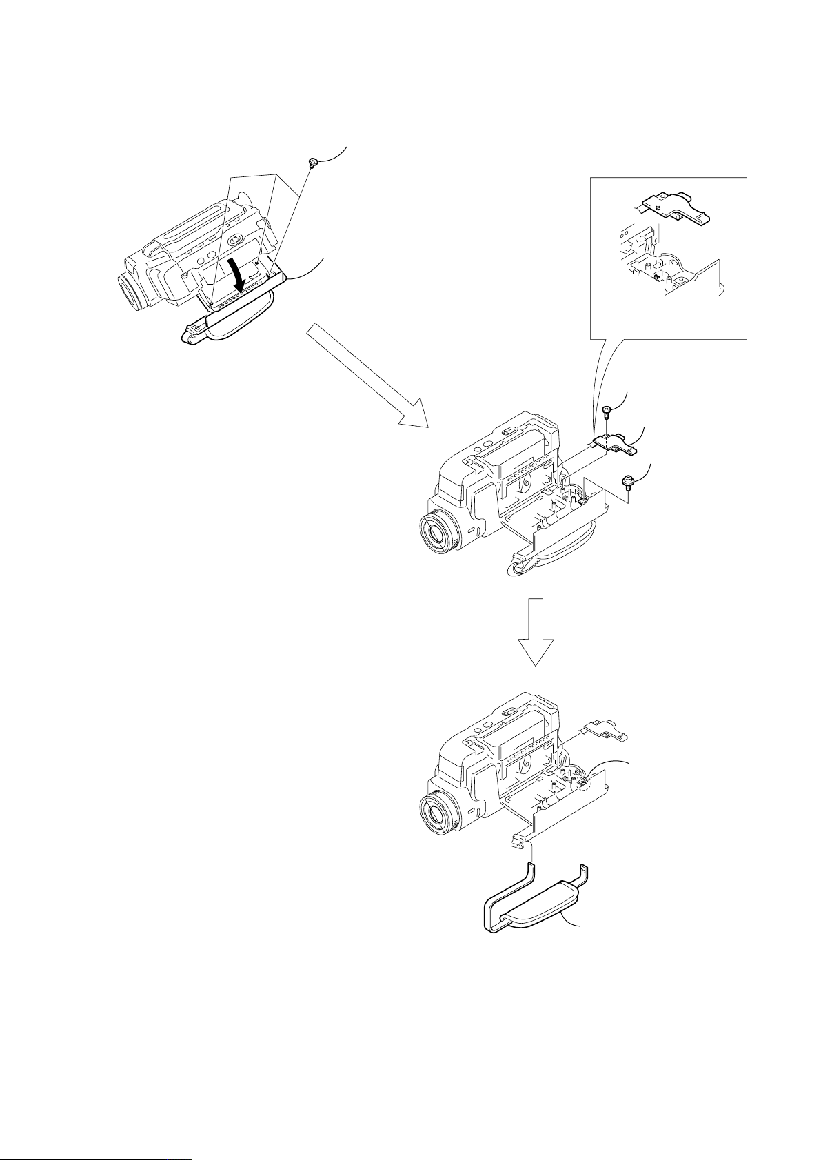
2-12. GRIP BELT
2 Three tapping screws
(M1.7 × 3.5)
1 Open the
cassette lid
PRECAUTION DURING
INSTALLATION
To attach, align the switch
position as shown.
3 Tapping screw
(M1.7 × 5)
4 Control switch block
(PS-1700)
5 Screw
(M2 × 4)
— 15 —
6 Claw
7 Grip belt

3. REPAIR PARTS LIST
3-1. EXPLODED VIEWS
NOTE:
• -XX, -X mean standardized parts, so they may
have some differences from the original one.
• Items marked “*” are not stocked since they
are seldom required for routine service. Some
delay should be anticipated when ordering these
items.
3-1-1. OVERALL SECTION
• The mechanical parts with no reference number
in the exploded views are not supplied.
The components identified by mark 0 or
dotted line with mark 0 are critical for safety.
Replace only with part number specified.
22
21
Cabinet (L) section
(See page 19)
17
16
B
2
9
10
8
1
C
VC-260
19
2
2
18
Cabinet (R) section
(See page 17)
12
1
C
11
20
1
20
14
13
1
15
7
2
B
5
6
2
2
A
2
4
A
3
2
MIC901
MIC902
not
supplied
1
Ref. No. Part No. Description Remarks Ref. No. Part No. Description Remarks
1 3-713-791-51 SCREW (M1.7X3.5), TAPPING, P2
2 3-989-735-81 SCREW (M1.7), LOCK ACE, P2
3 X-3951-424-1 PANEL (S) ASSY, FRONT
4 3-066-838-01 LIGHT, TALLY GUIDE
5 X-3950-537-1 CAP ASSY, LENS
6 X-3951-423-1 PANEL ASSY, FRONT
7 3-066-839-01 COVER, JACK
8 3-066-834-01 BUTTON, SNS
9 3-066-832-01 NS SW
10 3-066-833-01 BASE, NS
11 not supplied FB-218 BOARD, COMPLETE
12 A-7074-780-A FP-311 FLEXIBLE BOARD, COMPLETE
13 not supplied MA-403 (R) BOARD, COMPLETE
* 14 3-057-438-11 CUSHION, LIGHT INTERCEPTION
15 1-681-258-11 PWB, FP-304 FLEXIBLE BOARD
16 3-066-737-31 PLATE, JACK ORNAMENTAL (TRV17E)
16 3-066-737-41 PLATE, JACK ORNAMENTAL (TRV15E)
17 3-067-081-31 SHEET, POWER (TRV17E)
17 3-067-081-41 SHEET, POWER (TRV15E)
18 X-3951-426-1 CABINET ASSY, TOP
19 3-066-843-01 WINDOW, INDICATION
20 3-069-101-01 SHEET, SENSOR
21 1-475-141-61 REMOTE COMMANDER (RMT-814)
22 3-742-854-01 LID, BATTERY CASE (FOR RMT-814)
MIC901 1-542-312-11 MICROPHONE (Lch)
MIC902 1-542-312-11 MICROPHONE (Rch)
— 16 —
3-1-2. CABINET (R) SECTION
58
CK-101
SP901
68
LCD902
59
67
60
53
62
63
65
not
supplied
LCD section
(See page 18)
69
64
57
Ref. No. Part No. Description Remarks Ref. No. Part No. Description Remarks
51 3-055-257-01 TRIPOD (LARGE)
* 52 3-055-258-01 SHEET, TRIPOD INSULATNG
53 X-3951-440-1 FRAME ASSY, BOTTOM
54 1-757-770-11 CABLE, FLEXIBLE FLAT (FFC-314)
* 55 3-055-885-01 SHEET, MUFFLE
56
66
54
55
: BT8301 (Lithium battery) CK-101 board on the mount position.
52
51
61
62 X-3951-422-1 CABINET (R) ASSY
63 X-3951-551-1 BUTTON ASSY, VTR (TRV17E)
63 X-3951-552-1 BUTTON ASSY, VTR (TRV15E)
64 3-945-884-11 SCREW (2X6)
65 3-066-738-31 SHEET, KEY (TRV17E)
* 56 X-3950-471-1 RETAINER ASSY, SPEAKER
57 3-713-791-51 SCREW (M1.7X3.5), TAPPING, P2
58 not supplied CK-101 (FBFBO) BOARD, COMPLETE (TRV17E)
58 not supplied CK-101 (FBO) BOARD, COMPLETE (TRV15E)
59 1-476-580-11 SWITCH BLOCK, CONTROL (KP-1700)
60 3-055-324-01 KNOB, EJECT
61 3-055-573-01 SCREW (M1.7), LOCK ACE, P2
65 3-066-738-41 SHEET, KEY (TRV15E)
66 3-068-839-01 SHEET, FOCUS
67 3-713-791-11 SCREW (M1.7X5), TAPPING, P2
68 3-941-343-21 TAPE (A)
69 3-841-069-11 SPACER
LCD902 not supplied INDICATION LCD BLOCK ASSY
SP901 1-529-590-11 SPEAKER (2.0CM)
— 17 —
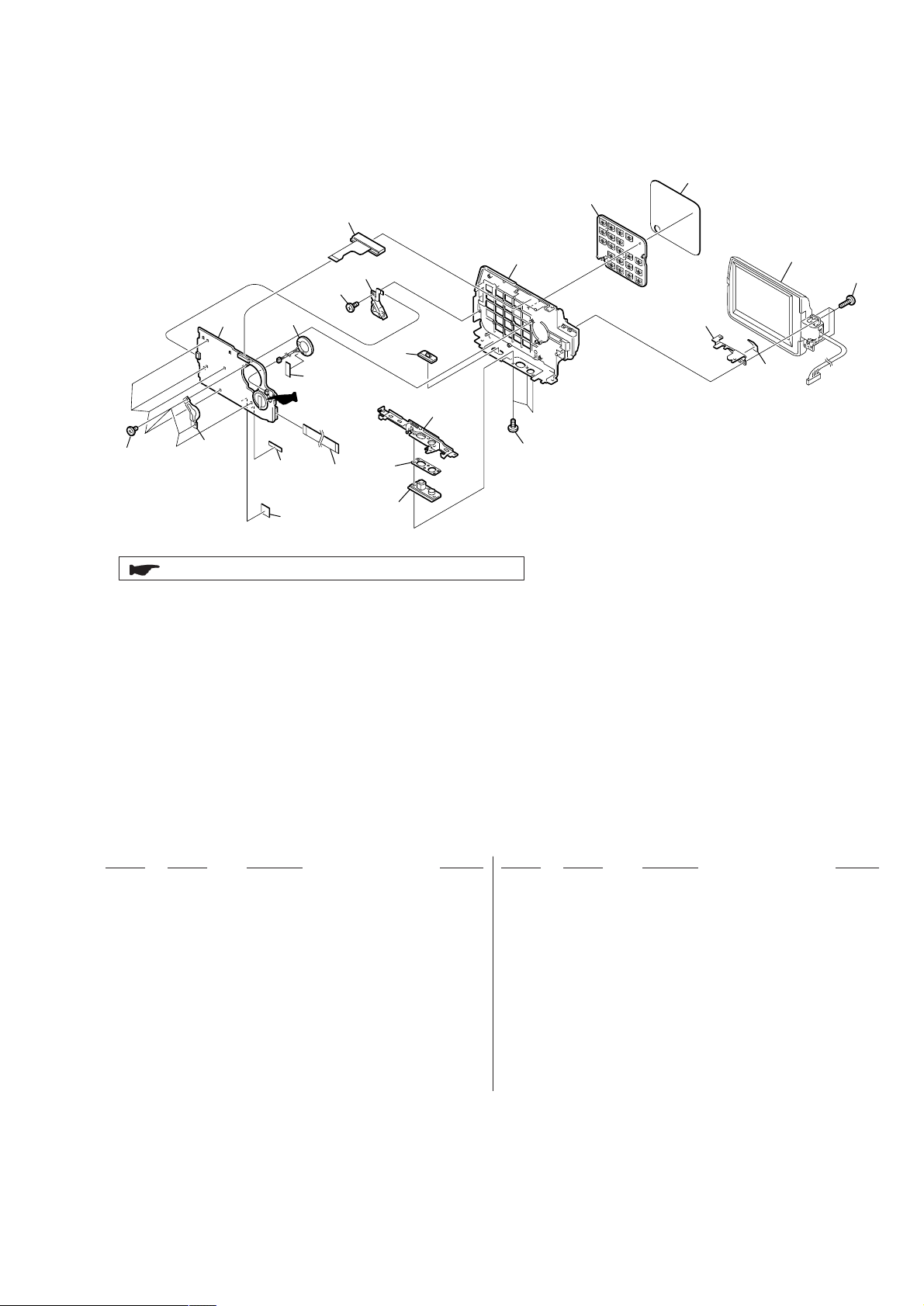
3-1-3. LCD SECTION
103
106
104
105
107
110
ND901
115
(TRV17E)
B
LCD901
A
113
B
103
114
101
B
not
supplied
108
102
A
109
103
101
PD-143
111
112
LCD901
(TRV15E)
113
A
ND901
Ref. No. Part No. Description Remarks Ref. No. Part No. Description Remarks
101 3-968-729-91 SCREW (M2), LOCK ACE, P2
102 X-3951-421-1 CABINET (C) ASSY, P
103 4-974-725-01 SCREW (M1.7X2.5), P
104 3-066-822-01 COVER (FRONT), HINGE
105 X-3951-724-1 HINGE ASSY (1730)
106 A-7074-778-A FP-309 FLEXIBLE BOARD, COMPLETE
107 3-066-823-01 COVER (REAR), HINGE
108 1-961-121-11 HARNESS (PV-130)
109 not supplied PD-143 (35SH123) BOARD, COMPLETE
(TRV17E)
109 not supplied PD-143 (25SH123) BOARD, COMPLETE
(TRV15E)
110 X-3951-420-1 FRAME ASSY (3.5), P (TRV17E)
110 X-3951-547-1 FRAME ASSY (2.5), P (TRV15E)
— 18 —
111 3-059-740-01 SPRING (P), TORSION
112 3-059-739-01 BUTTON, PANEL OPEN
113 3-066-821-01 CABINET (M) (3.5), P (TRV17E)
113 3-067-753-01 CABINET (M) (2.5), P (TRV15E)
114 3-066-736-31 PLATE, P ORNAMENTAL (TRV17E)
114 3-066-736-41 PLATE, P ORNAMENTAL (TRV15E)
115 3-069-291-01 BL SHEET (TRV17E)
LCD901 not supplied INDICATOR MODULE LIQUID CRYST (2.5)
(TRV15E)
LCD901 not supplied INDICATOR MODULE LIQUID CRYST (3.5)
(TRV17E)
0 ND901 not supplied TUBE, FLUORESCENT, COLD CATHODE (3.5)
(TRV17E)
0 ND901 not supplied TUBE, FLUORESCENT, COLD CATHODE (2.5)
(TRV15E)
Note : The components identified by mark 0 or dotted
line with mark 0 are critical for safety.
Replace only with part number specified.
3-1-4. CABINET (L) SECTION
A
A
B
B
C
D
F
G
I
I
H
H
F
E
C
D
E
VC-260
J
K
J
K
G
BT901
not supplied
not
supplied
151
152
153
154
155
157
158
159
160
161
162
162
162
162
163
164
165
166
167
153
168
160
160
169
156
153
EVF section
(See page 21)
Main chassis complete
section (See page 20)
Ref. No. Part No. Description Remarks Ref. No. Part No. Description Remarks
151 X-3951-427-1 CABINET ASSY, GRIP (TRV17E)
151 X-3951-548-1 CABINET ASSY, GRIP (TRV15E)
* 152 3-055-189-01 FOOT (A)
153 3-713-791-11 SCREW (M1.7X5), TAPPING, P2
154 3-059-825-01 BRACKET (FRONT), GRIP BELT
155 3-061-550-01 BELT, GRIP
156 3-679-362-11 SCREW
157 X-3951-419-1 CABINET (L) ASSY (TRV17E)
157 X-3951-549-1 CABINET (L) ASSY (TRV15E)
158 1-476-579-11 SWITCH BLOCK, CONTROL (PS-1700)
159 A-7074-779-A FP-310 FLEXIBLE BOARD, COMPLETE
160 4-974-725-01 SCREW (M1.7X2.5), P
161 X-3951-438-1 FRAME ASSY, CS
162 3-713-791-51 SCREW (M1.7X3.5), TAPPING, P2
163 3-067-024-01 BRACKET (LOWER), STRAP
164 X-3951-428-1 PANEL ASSY, BT
165 3-989-735-81 SCREW (M1.7), LOCK ACE, P2
166 3-067-025-01 CPC LID
167 A-7074-777-A FP-305 FLEXIBLE BOARD, COMPLETE
168 3-066-847-01 SPACER, M
169 3-068-717-01 CUSHION LL
BT901 1-694-772-11 TERMINAL BOARD, BATTERY
— 19 —
3-1-5. MAIN CHASSIS COMPLETE SECTION
207
D
C
212
211
A
B
210
Mechanism deck
209
207
206
203
202
204
218
219
205
IC8001
207
(TRV17E)
208
201
213
(TRV15E)
217
214
MS-070
(TRV17E)
215
207
B
A
D
C
VC-260
216
207
Ref. No. Part No. Description Remarks Ref. No. Part No. Description Remarks
201 1-681-260-11 PWB, FP-306 FLEXIBLE BOARD
202 not supplied SCREW (M1.7X5), TAPPING, P2
203 not supplied CD-303 BOARD, COMPLETE
204 not supplied RUBBER (W), SEAL
205 not supplied FILTER BLOCK, OPTICAL
206 not supplied DEVICE, LENS LSV-650D
207 4-974-725-01 SCREW (M1.7X2.5), P
208 1-681-261-11 PWB, FP-307 FLEXIBLE BOARD (TRV17E)
209 not supplied JK-204 (FBFB) BOARD, COMPLETE (TRV17E)
209 not supplied JK-204 (FB) BOARD, COMPLETE (TRV15E)
210 3-059-722-01 COVER, CASSETTE COMPARTMENT
211 3-713-791-51 SCREW (M1.7X3.5), TAPPING, P2
212 1-815-124-11 CONNECTOR, EXTERNAL (HOT SHOE)(TRV17E)
212 1-815-124-21 CONNECTOR, EXTERNAL (HOT SHOE)(TRV15E)
213 X-3951-425-1 FRAME ASSY, MAIN
214 3-059-718-01 SCREW (M1.4X1.5)
215 not supplied MS-070 BOARD, COMPLETE (TRV17E)
216 not supplied VC-260 (FBO) BOARD, COMPLETE (SERVICE)
(TRV15E)
216 not supplied VC-260 (FBFBO) BOARD, COMPLETE
(SERVICE) (TRV17E)
217 1-681-267-11 PWB, FP-314 FLEXIBLE BOARD (TRV15E)
218 1-500-226-31 BEAD, FERRITE
219 3-069-697-01 LF SHIELD SHEET
IC8001 not supplied CCD BLOCK ASSY (CCD IMAGER)
— 20 —
3-1-6. EVF SECTION
262
254
253
255
256
259
257
252
(TRV17E)
260
258
LCD903
263
261
264
265
266
265
267
251
Ref. No. Part No. Description Remarks Ref. No. Part No. Description Remarks
251 3-067-819-01 SHEET, VF FLEXIBLE RETAINER
252 A-7074-781-A FP-313 FLEXIBLE BOARD, COMPLETE (TRV17E)
253 3-067-067-01 GUIDE, VF FLEXIBLE
254 1-681-268-11 PWB, FP-320 FLEXIBLE BOARD
255 not supplied LB-069 BOARD, COMPLETE
256 3-065-058-01 GUIDE, LAMP
257 not supplied ILLUMINATOR (1)
258 not supplied SHEET (2) (138), PRISM
259 not supplied SHEET (1) (138), PRISM
260 3-065-062-01 CUSHION (138), LCD
261 3-059-734-01 CUSHION (1), LCD
262 X-3951-451-1 CABINET (UPPER) ASSY, VF
263 X-3951-453-1 LENS ASSY, VF
264 X-3951-452-1 CABINET (LOWER) ASSY, VF
265 3-713-791-11 SCREW (M1.7X5), TAPPING, P2
266 X-3951-441-1 BASE ASSY, VF (TRV17E)
266 X-3951-559-1 BASE ASSY, VF (TRV15E)
LCD903 not supplied LCX032AN-J
— 21 —
DCR-TRV15E/TRV17E
English
Main Features
Taking moving or still images, and playing them back
•Recording a picture (p. 28)
•Recording a still image on a tape (p. 49)
•Playing back a tape (p. 41)
•Recording still images on “Memory Stick”s (p. 141) (DCR-TRV17E only)
•Recording moving pictures on “Memory Stick”s (p. 149) (DCR-TRV17E only)
•Viewing a still image recorded on “Memory Stick” (p. 159) (DCR-TRV17E only)
•Viewing a moving picture recorded on “Memory Stick” (p. 163) (DCR-TRV17E only)
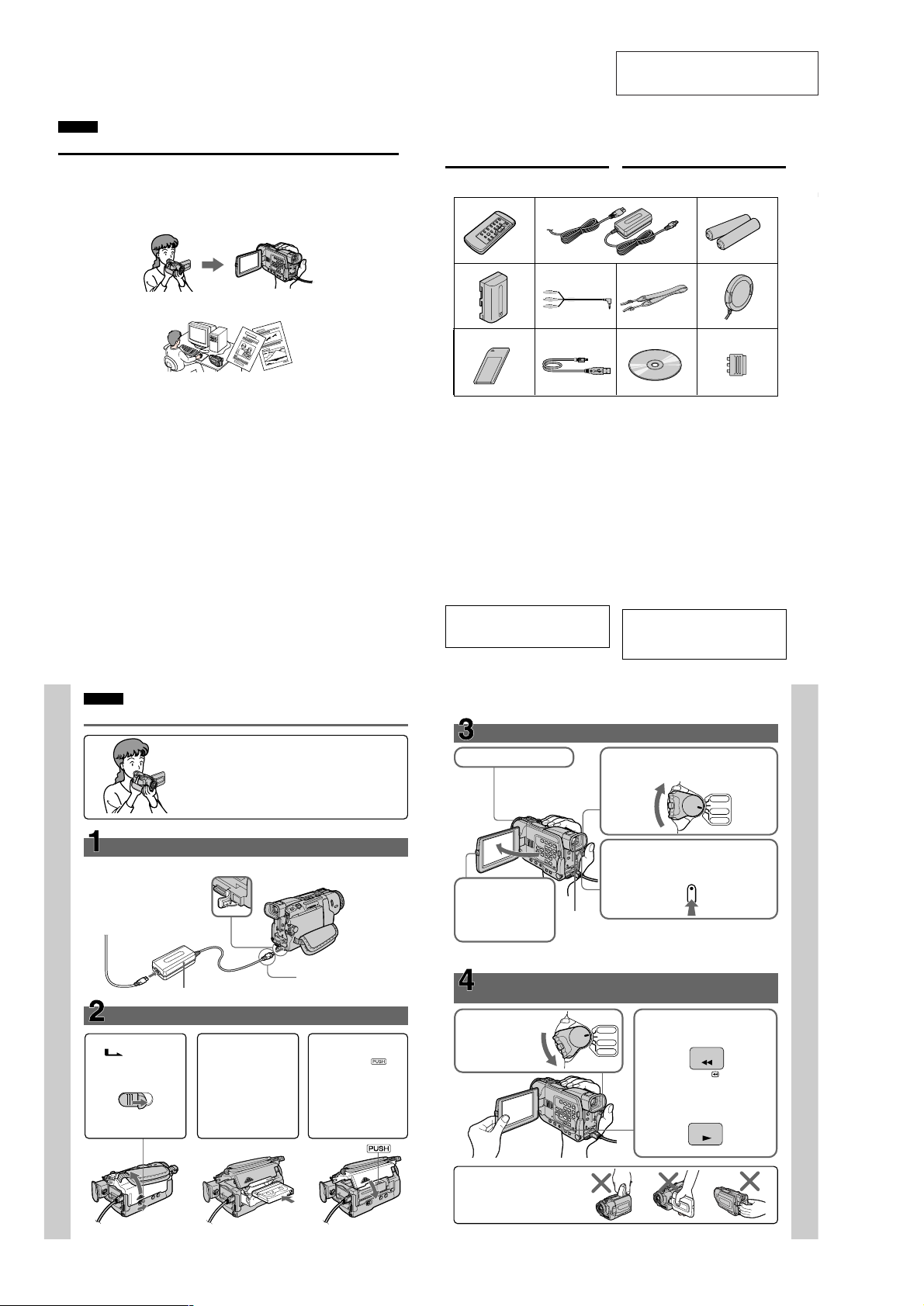
2. GENERAL
Checking supplied
accessories
Make sure that the following accessories are
supplied with your camcorder.
12
This section is extracted from
instruction manual.
Проверка прилагаемых
принадлежностей
Убедитесь, что следующие принадлежности
прилагаются к Вашей видеокамере.
3
Getting started Подготовка к эксплуатации
Capturing images on your computer
•Viewing images recorded on “Memory Stick” using USB cable (p. 165) (DCR-TRV17E only)
Other uses
Functions to adjust exposure in the recording mode
• Back light (p. 35)
• NightShot/Super NightShot (p. 35)
• PROGRAM AE (p. 63)
• Adjusting the exposure manually (p. 66)
Functions to give images more impact
• Digital zoom (p. 33) The default setting is set to OFF. (To zoom greater than 10×, select the digital
zoom power in D ZOOM in the menu settings.)
• Fader (p. 56)
• Picture effect (p. 59)
• Digital effect (p. 60)
• Digital program editing (p. 90)
• Title (p. 106, 110)
• MEMORY MIX (p. 153) (DCR-TRV17E only)
Functions to give a natural appearance to your recordings
• Landscape mode (p. 63)
• Sports lesson mode (p. 63)
• Manual focus (p. 67)
Functions to use after recording
• END SEARCH/EDITSEARCH/Rec review (p. 39)
• DATA CODE (p. 42)
• SUPER LASER LINK (p. 48)
• Tape PB ZOOM (p. 77)/Memory PB ZOOM (p. 172) (DCR-TRV17E only)
• Zero set memory (p. 78)
• Title search (p. 79)
• HiFi SOUND (p. 116)
English
Quick Start Guide
This chapter introduces you to the basic features of your
camcorder. See the page in parentheses “()” for more
information.
45
8
1 Wireless Remote Commander (1) (p. 228)
2 AC-L10A/L10B/L10C AC power adaptor
(1), Mains lead (1) (p. 18)
3 R6 (Size AA) battery for Remote
Commander (2) (p. 228)
4 NP-FM30 battery pack (1) (p. 17, 18)
5 A/V connecting cable (1) (p. 46, 86)
6 Shoulder strap (1) (p. 223)
7 Lens cap (1) (p. 28)
8 “Memory Stick” (1) (p. 131)
DCR-TRV17E only
9 USB cable (1) (p. 167)
DCR-TRV17E only
q; CD-ROM (SPVD-004, USB Driver) (1)
(p. 167)
DCR-TRV17E only
qa 21-pin adaptor (1) (p. 47)
Contents of the recording cannot be
compensated if recording or playback is not
made due to a malfunction of the camcorder,
storage media, etc.
3
Recording a picture (p. 28)
1Remove the lens cap.
POWER
7
qa
(1)
(стр. 28)
5
PLAYER
OFF(CHG)
CAMERA
MEMORY
6
9
q;
1 Беспроводной пульт дистанционного
управления (1) (стр. 228)
2 Сетевой адаптер переменного тока
AC-L10A/L10B/L10C (1), провод
электропитания (1) (стр. 18)
3 Батарейка R6 (размера АА) для
пульта дистанционного управления
(2) (стр. 228)
Батарейный блок NP-FM30 (1) (стр. 17, 18)
4
5 Соединительный кабель аудио/видео
(1) (стр. 46, 86)
6 Плечевой ремень (1) (стр. 223)
7 Крышка объектива
8 “Memory Stick” (1) (стр. 131)
Только модель DCR-TRV17E
9 Кабель USB (1) (стр. 167)
Только модель DCR-TRV17E
q; CD-ROM (SPVD-004, драйвер USB) (1)
(стр. 167)
Только модель DCR-TRV17E
qa 21-штырьковый адаптер (1) (стр. 47)
Содержимое записи не может быть
компенсировано, если запись или
воспроизведение не выполняется
вследствие повреждения видеокамеры,
носителя данных и т.д.
2Set the POWER switch to CAMERA while
pressing the small green button.
Quick Start Guide
1
10
Connecting the mains lead
Use the battery pack when using your camcorder outdoors (p. 17).
Open the DC IN
jack cover.
AC power adaptor (supplied)
Inserting a cassette
2
Slide OPEN/
EJECT in the
direction of the arrow
and open the lid.
EJECT
Push the middle
portion of the back of
the cassette to insert.
Insert the cassette in a
straight line deeply
into the cassette
compartment with the
window facing out.
(p. 26)
(p. 23)
Connect the plug with its v
mark facing up.
3
Close the cassette
compartment by
pressing the
mark on the cassette
compartment.
After the cassette
compartment going
down completely,
close the lid until it
clicks.
— 22 —
4Press START/STOP. Your camcorder starts
recording. To stop recording, press START/
STOP again.
3To open the LCD
panel, press OPEN.
The picture appears on
the screen.
When you purchase your camcorder, the clock setting is set to off. If you want to record the date
and time for a picture, set the clock setting before recording (p. 24).
Monitoring the playback picture on the LCD
screen (p. 41)
1Set the POWER
switch to
PLAYER while
pressing the small
green button.
Viewfinder
When the LCD panel is closed, use the viewfinder
placing your eye against its eyecup.
2Press m to rewind the tape.
PLAYER
OFF(CHG)
R
E
OW
P
CAMERA
MEMORY
REW
3Press N to start playback.
PLAY
NOTE
Do not pick up your camcorder by
holding the viewfinder, the LCD
panel, or the battery pack.
Quick Start Guide
11
 Loading...