

Sony DCR-TRV12E, DCR-TRV14E, DCR-TRV19, DCR-TRV19E Service Manual

DCR-TRV12E/TRV14E/
TRV19/TRV19E
RMT-814
SERVICE MANUAL
Ver 1.3 2003. 11
Revision History
Revision History
Z MECHANISM
Link
Link
SPECIFICATIONS
BLOCK DIAGRAMS
BLOCK DIAGRAMS
LEVEL 2
US Model
Canadian Model
Korea Model
DCR-TRV19
AEP Model
East European Model
North European Model
DCR-TRV12E/TRV14E/TRV19E
UK Model
DCR-TRV14E/TRV19E
E Model
Hong Kong Model
DCR-TRV19/TRV19E
Australian Model
Chinese Model
DCR-TRV19E
PRINTED WIRING BOARDS
PRINTED WIRING BOARDSSPECIFICATIONS
SERVICE NOTE
SERVICE NOTE
DISASSEMBLY
DISASSEMBLY
• For INSTRUCTION MANUAL, refer to SERVICE MANUAL, LEVEL 1 (987622441.pdf).
• For MECHANISM ADJUSTMENTS, refer to the “DV MECHANICAL ADJUSTMENT MANUAL
Z MECHANISM ” (9-876-210-11).
On the VC-311 board
This service manual provides the information that is premised the circuit board replacement service and not intended repair
inside the VC-311 board.
Therefore, schematic diagram, printed wiring board, waveforms, mounted parts location and electrical parts list of the VC-311
board are not shown.
The following pages are not shown.
Schematic diagram .............................Pages 4-37 to 4-52
Printed wiring board............................Pages 4-73 to 4-76
Waveforms ...........................................
FRAME SCHEMATIC DIAGRAMS
FRAME SCHEMATIC DIAGRAMS
SCHEMATIC DIAGRAMS
SCHEMATIC DIAGRAMS
Mounted parts location .............................
Electrical parts list................................... Pages 5-21 to 5-24
Page 4-79 to 4-80
REPAIR PARTS LIST
REPAIR PARTS LIST
Page 4-83
DIGITAL VIDEO CAMERA RECORDER

DCR-TRV12E/TRV14E/TRV19/TRV19E
COVER
COVER
Video camera
recorder
System
Video recording system
2 rotary heads
Helical scanning system
Audio recording system
Rotary heads, PCM system
Quantization: 12 bits (Fs 32 kHz,
stereo 1, stereo 2), 16 bits
(Fs 48 kHz, stereo)
Video signal
DCR-TRV19:
NTSC colour, EIA standards
DCR-TRV12E/TRV14E/TRV19E:
PAL colour, CCIR standards
Usable cassette
Mini DV cassette with the
mark printed
Tape speed
SP: Approx. 18.81 mm/s
LP: Approx. 12.56 mm/s
Recording/playback time
(using cassette DVM60)
SP: 1 hour
LP: 1.5 hours
Fastforward/rewind time
(using cassette DVM60)
Approx. 2 min. and 40 seconds
Viewfinder
Electric viewfinder
black and white
Image device
DCR-TRV12E/TRV14E/TRV19E:
4.5 mm (1/4 type)
CCD (Charge Coupled Device)
Gross:
DCR-TRV19:
Approx. 680 000 pixels
DCR-TRV12E/TRV14E/TRV19E:
Effective (moving):
DCR-TRV19: Approx. 340 000 pixels
DCR-TRV12E/TRV14E/TRV19E:
Lens
Carl Zeiss Vario-Sonnar
Combined power zoom lens
Filter diameter: 30 mm
(1 3/16 in)
10× (Optical), 120× (Digital)
Focal length
3.3 – 33 mm (5/32 – 1 5/16 in.)
42 – 420 mm (1 11/16 – 16 5/8
2)
in.)
1)
When converted to a 35 mm still
camera
2)
In CAMERA mode
Colour temperature
Auto, HOLD, INDOOR (3 200 K),
OUTDOOR (5 800 K)
Minimum illumination
5 lx (lux) (F1.7)
0 lx (lux) (in the NightShot
mode)*
* Objects unable to be seen due to
the dark can be shot with
infrared lighting.
Input/Output connectors
S video output
4-pin mini DIN
(DCR-TRV19/TRV19E only)
Luminance signal: 1 Vp-p,
75 Ω
(ohms), unbalanced
Chrominance signal:
DCR-TRV19:
0.286 Vp-p
DCR-TRV12E/TRV14E/TRV19E:
0.3 Vp-p
75 Ω
(ohms), unbalanced
Audio/Video output
AV MINI JACK, 1 Vp-p,
75 Ω (ohms), unbalanced
327 mV, (at output impedance
more than 47 kΩ (kilohms))
Output impedance with less than
2.2 kΩ (kilohms)/Stereo minijack
(ø 3.5 mm)
Input impedance more than
47 kΩ (kilohms)
DV input (DCR-TRV19/TRV19E
only)/output
4-pin connector
Headphone jack
Stereo minijack (ø 3.5 mm)
LANC jack
Stereo mini-minijack (ø 2.5 mm)
USB jack
mini-B
SPECIFICATIONS
MIC jack
1)
Minijack, 0.388 mV low impedance
with 2.5 to 3.0 V DC, output
impedance 6.8 kΩ (kilohms)
(ø 3.5 mm)
Stereo type
LCD screen
Picture
6.2 cm (2.5 type)
50.3 × 37.4 mm (2 × 1 1/2 in.)
Total dot number
123 200 (560 × 220)
General
Power requirements
7.2 V (battery pack)
8.4 V (AC Adaptor)
Average power consumption
(when using the battery pack)
1)
3.3 W
2)
2.5 W
1)
During camera recording using
LCD
2)
Viewfinder
Operating temperature
0°C to 40°C (32°F to 104°F)
Storage temperature
–20°C to + 60°C
(–4°F to + 140°F)
Dimensions (approx.)
71 × 90 × 112 mm
(2 7/8 × 3 5/8 × 4 1/2 in.) (w/h/d)
Mass (approx.)
Main unit only
520 g (1 lb 2 oz)
Including the rechargeable battery
pack NP-FM30, cassette DVM60
and lens cap
610 g (1 lb 5 oz)
Supplied accessories
See page 3.
AC Adaptor
AC-L15A/L15B
Power requirements
100 – 240 V AC, 50/60 Hz
Current consumption
0.35 – 0.18 A
Power consumption
18 W
Output voltage
DC OUT: 8.4 V, 1.5 A
Operating temperature
0°C to 40°C (32°F to 104°F)
Storage temperature
–20°C to + 60°C
(–4°F to + 140°F)
Dimensions (approx.)
56 × 31 × 100 mm
(2 1/4 × 1 1/4 × 4 in.) (w/h/d)
excluding projecting parts
Mass (approx.)
190 g (6.7 oz)
excluding power cord
Rechargeable
battery pack
NP-FM30
Maximum output voltage
DC 8.4 V
Output voltage
DC 7.2 V
Capacity
5.0 Wh (700 mAh)
Dimensions (approx.)
38.2 × 20.5 × 55.6 mm
(1 9/16 × 13/16 × 2 1/4 in.)
(w/h/d)
Mass (approx.)
65 g (2.3 oz)
Operating temperature
0°C to 40°C (32°F to 104°F)
Type
Lithium ion
Design and specifications are
subject to change without notice.
CAUTION :
Danger of explosion if battery is incorrectly replaced.
Replace only with the same or equivalent type.
SAFETY-RELATED COMPONENT WARNING!!
COMPONENTS IDENTIFIED BY MARK 0 OR DOTTED LINE WITH
MARK 0 ON THE SCHEMATIC DIAGRAMS AND IN THE PARTS
LIST ARE CRITICAL TO SAFE OPERATION. REPLACE THESE
COMPONENTS WITH SONY PARTS WHOSE PART NUMBERS
APPEAR AS SHOWN IN THIS MANUAL OR IN SUPPLEMENTS
PUBLISHED BY SONY.
ATTENTION AU COMPOSANT AYANT RAPPORT
À LA SÉCURITÉ!
LES COMPOSANTS IDENTIFÉS PAR UNE MARQUE 0 SUR LES
DIAGRAMMES SCHÉMATIQUES ET LA LISTE DES PIÈCES SONT
CRITIQUES POUR LA SÉCURITÉ DE FONCTIONNEMENT. NE
REMPLACER CES COMPOSANTS QUE PAR DES PIÈSES SONY
DONT LES NUMÉROS SONT DONNÉS DANS CE MANUEL OU
DANS LES SUPPÉMENTS PUBLIÉS PAR SONY.
— 2 —

• SUPPLIED ACCESSORIES
Make sure that the following accessories are supplied with your camcorder .
DCR-TRV12E/TRV14E/TRV19/TRV19E
1
4
9
1 AC-L15A/L15B AC Adaptor (1), Power
cord (1)
2 NP-FM30 rechargeable battery pack
(1)
3 A/V connecting cable (1)
4 Wireless Remote Commander
RMT-814E (EXCEPT TRV12E)
5 R6 (size AA) battery for Remote
Commander (2)
6 Shoulder strap (1)
7 Lens cap (1)
5
q;
6
qa
(1)
2
7
qs
8 Shoe cover (1)
9 USB cable (1)
q; CD-ROM (USB Driver)
SPVD-010 (I), US, CND model only
SPVD-010 EXCEPT US, CND model only
qa Cleaning cloth (1)
qs 21-pin adaptor* (1) (AEP, UK, EE, NE model only)
*
The models with mark printed on their
bottom surfaces only.
qd
2-pin conversion adaptor (1)
(E, HK only)
3
8
qd
(1)
• Abbreviation
CND : Canadian model
EE : East European model
NE : North European model
HK : Hong Kong model
SAFETY CHECK-OUT
After correcting the original service problem, perform the following
safety checks before releasing the set to the customer.
1. Check the area of your repair for unsoldered or poorly-soldered
connections. Check the entire board surface for solder splashes
and bridges.
2. Check the interboard wiring to ensure that no wires are
"pinched" or contact high-wattage resistors.
3. Look for unauthorized replacement parts, particularly
transistors, that were installed during a previous repair. Point
them out to the customer and recommend their replacement.
4. Look for parts which, through functioning, show obvious signs
of deterioration. Point them out to the customer and
recommend their replacement.
5. Check the B+ voltage to see it is at the values specified.
6. Flexible Circuit Board Repairing
• Keep the temperature of the soldering iron around 270˚C
during repairing.
• Do not touch the soldering iron on the same conductor of the
circuit board (within 3 times).
• Be careful not to apply force on the conductor when soldering
or unsoldering.
Unleaded solder
Boards requiring use of unleaded solder are printed with the leadfree mark (LF) indicating the solder contains no lead.
(Caution: Some printed circuit boards may not come printed with
the lead free mark due to their particular size.)
: LEAD FREE MARK
Unleaded solder has the following characteristics.
• Unleaded solder melts at a temperature about 40°C higher than
ordinary solder.
Ordinary soldering irons can be used but the iron tip has to be
applied to the solder joint for a slightly longer time.
Soldering irons using a temperature regulator should be set to
about 350°C.
Caution: The printed pattern (copper foil) may peel away if the
heated tip is applied for too long, so be careful!
• Strong viscosity
Unleaded solder is more viscous (sticky, less prone to flow) than
ordinary solder so use caution not to let solder bridges occur such
as on IC pins, etc.
• Usable with ordinary solder
It is best to use only unleaded solder but unleaded solder may
also be added to ordinary solder.
— 3 —

DCR-TRV12E/TRV14E/TRV19/TRV19E
TABLE OF CONTENTS
1. SERVICE NOTE
1-1. SERVICE NOTE ·····························································1-1
1. POWER SUPPLY DURING REPAIRS··························1-1
2. TO TAKE OUT A CASSETTE WHEN NOT EJECT
(FORCE EJECT) ····························································· 1-1
1-2. SELF-DIAGNOSIS FUNCTION····································1-2
1. SELF-DIAGNOSIS FUNCTION····································1-2
2. SELF-DIAGNOSIS DISPLAY ·······································1-2
3. SELF-DIAGNOSIS CODE TABLE································ 1-3
2. DISASSEMBLY
2-1. P CABINET (C) ASSEMBLY ········································2-3
2-2. CABINET (R) COVER (39E) ASSEMBLY ···················2-4
2-3. F PANEL SECTION ······················································· 2-5
2-4. MA-421 BOARD ····························································2-6
2-5. CABINET (R) SECTION ···············································2-7
2-6. LCD SECTION ·······························································2-8
2-7. CK-129 BOARD,
CONTROL SWITCH BLOCK(CF-CX4000)·················2-8
2-8. PD-188 BOARD, LCD UNIT ·········································2-9
2-9. HINGE (40) ASSEMBLY ············································· 2-10
2-10. BT PANEL/EVF SECTION··········································2-11
2-11. LB-085 BOARD (REMOVING OF THE EVF)-1········2-12
2-12. LB-085 BOARD (REMOVING OF THE EVF)-2········2-13
2-13. LB-085 BOARD (REMOVING OF THE EVF)-3········2-14
2-14. VA-118 BOARD, LENS SECTION······························2-15
2-15. CD-430 BOARD ··························································· 2-16
2-16. MECHANISM DECK, VC-312 BOARD (1) ··············· 2-16
2-17. MECHANISM DECK, VC-312 BOARD (2) ··············· 2-17
2-18. CABINET (G) ASSEMBLY (40E) ·······························2-17
2-19. CONTROL SWITCH BLOCK (FK-CX4000)··············2-18
2-20. JK-242 BOARD ····························································2-18
2-21. CIRCUIT BOARDS LOCATION ································· 2-20
2-22. FLEXIBLE BOARDS LOCATION ······························2-21
3. BLOCK DIAGRAMS
3-1. OVERALL BLOCK DIAGRAM (1/4) ···························3-1
3-2. OVERALL BLOCK DIAGRAM (2/4) ···························3-3
3-3. OVERALL BLOCK DIAGRAM (3/4) ···························3-5
3-4. OVERALL BLOCK DIAGRAM (4/4) ···························3-7
3-5. POWER BLOCK DIAGRAM (1/2) ································3-9
3-6. POWER BLOCK DIAGRAM (2/2) ······························3-11
• PD-188 (2/2)(BACKLIGHT DRIVE)
SCHEMATIC DIAGRAM····························4-25
• JK-242 (A.V/DV IN/OUT)
SCHEMATIC DIAGRAM····························4-27
• CONTROL SWITCH BLOCK (FK-CX4000)
SCHEMATIC DIAGRAM····························4-29
• MA-421 (1/2)(MIC AMP)
SCHEMATIC DIAGRAM····························4-31
• MA-421 (2/2)(Y/P SENSOR, V/A IN/OUT)
SCHEMATIC DIAGRAM····························4-33
• FP-467/468/228 FLEXIBLE (S/T REEL SENSOR,
TAPE SENSOR)
SCHEMATIC DIAGRAM····························4-35
Shematic diagram of the VC-311 board are not shown.
Pages from 4-37 to 4-52 are not shown.
4-3. PRINTED WIRING BOARDS
• CD-430 (CCD IMAGER)
PRINTED WIRING BOARD ·······················4-55
• LB-085 (EVF, BACK LIGHT)
PRINTED WIRING BOARD ·······················4-57
• FP-467/468/228 FLEXIBLE BOARD
(S/T REEL SENSOR, TAPE SENSOR) ·····················4-59
• FP-626 FLEXIBLE BOARD ·····································4-59
• VA-118 (RGB DRIVE, TG, HI CONTROL, Y/P
SENSOR AMP, CONNECTOR, DC/DC COVERTER,
POWER IN, CHARGE)
PRINTED WIRING BOARD ·······················4-61
• CK-129 (FUNCTION SWITCH)
PRINTED WIRING BOARD ·······················4-65
• PD-188 (DRIVER, TG, BACKLIGHT DRIVE)
PRINTED WIRING BOARD ·······················4-67
• JK-242 (A.V/DV IN/OUT)
PRINTED WIRING BOARD ·······················4-69
• MA-421 (MIC AMP, Y/P SENSOR, V/A IN/OUT)
PRINTED WIRING BOARD ·······················4-71
Printed wiring board of the VC-311 board are not shown.
Pages from 4-73 to 4-76 are not shown.
4-4. WAVEFORMS ······························································4-77
4. PRINTED WIRING BOARDS AND
SCHEMATIC DIAGRAMS
4-1. FRAME SCHEMATIC DIAGRAM (1/3)·······················4-1
FRAME SCHEMATIC DIAGRAM (2/3)·······················4-3
FRAME SCHEMATIC DIAGRAM (3/3)·······················4-5
4-2. SCHEMATIC DIAGRAMS
• CD-430 (CCD IMAGER)
SCHEMATIC DIAGRAM······························4-9
• LB-085 (EVF, BACK LIGHT)
SCHEMATIC DIAGRAM····························4-10
• VA-118 (1/5)(RGB DRIVE, TG)
SCHEMATIC DIAGRAM····························4-11
• VA-118 (2/5)(HI CONTROL)
SCHEMATIC DIAGRAM····························4-13
• VA-118 (3/5)(Y/P SENSOR AMP, CONNECTOR)
SCHEMATIC DIAGRAM····························4-15
• VA-118 (4/5)(DC/DC COVERTER)
SCHEMATIC DIAGRAM····························4-17
• VA-118 (5/5)(POWER IN, CHARGE)
SCHEMATIC DIAGRAM····························4-19
• CK-129 (FUNCTION SWITCH)
SCHEMATIC DIAGRAM····························4-21
• PD-188 (1/2)(DRIVER, TG)
SCHEMATIC DIAGRAM····························4-23
Waveforms of the VC-311 board are not shown.
Pages 4-79 and 4-80 are not shown.
4-5. MOUNTED PARTS LOCATION ·································4-81
Mounted parts location of the VC-311 board is not shown.
Page 4-83 is not shown.
5. REPAIR PARTS LIST
5-1. EXPLODED VIEWS ······················································5-1
5-1-1.OVERALL SECTION·····················································5-3
5-1-2.F PANEL SECTION ·······················································5-4
5-1-3.MAIN CHASSIS SECTION ···········································5-5
5-1-4.LENS SECTION ·····························································5-6
5-1-5.CABINET L SECTION ··················································5-7
5-1-6.BT PANEL/EVF SECTION ············································5-8
5-1-7.CABINET R SECTION ··················································5-9
5-1-8.LCD SECTION ·····························································5-10
5-1-9.OVERALL (MECHANISM DECK-Z100)···················5-11
5-1-10. LS CHASSIS BLOCK ASSEMBLY ·························5-12
5-1-11. MECHANICAL CHASSIS BLOCK ASSEMBLY ···5-13
— 4 —

5-2. ELECTRICAL PARTS LIST ········································5-14
Parts list of the VC-311 board are not shown.
Pages from 5-21 to 5-24 are not shown.
DCR-TRV12E/TRV14E/TRV19/TRV19E
— 5 —
DCR-TRV12E/TRV14E/TRV19/TRV19E
)
COVER
COVER
SECTION 1
SERVICE NOTE
1-1. SERVICE NOTE
1. POWER SUPPLY DURING REPAIRS
In this unit, about 10 seconds after power is supplied to the battery terminal using the regulated power supply (8.4V), the po wer is shut of f so
that the unit cannot operate.
This following two methods are available to prevent this. Take note of which to use during repairs.
Method 1.
Use the AC power adaptor (AC-L10, AC-VQ800 etc.).
Method 2.
Connect the servicing remote commander RM-95 (J-6082-053-B) to the LANC jack, and set the commander switch to the “ADJ” side.
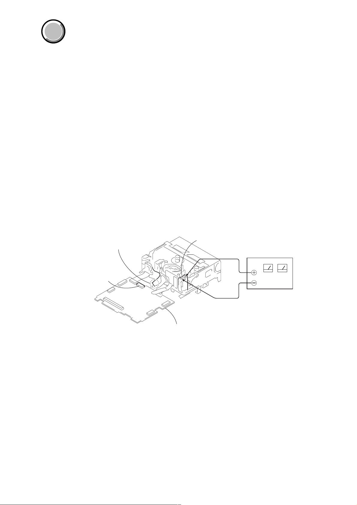
2. TO TAKE OUT A CASSETTE WHEN NOT EJECT (FORCE EJECT)
1 Refer to 2-2 to remove the cabinet (R) cover (39E).
2 Refer to 2-3 to remove the F panel section.
3 Refer to 2-10 to remove the BT panel/EVF section.
4 Refer to 2-14 to remove the VA-118 board and Lens section.
5 Refer to 2-16 to remove the VC-311 board and Mechanism deck.
6 Refer to 2-17 to remove the MD frame assembly from the VC-311 board and Mechanism deck.
7 Disconnect the flexible board from CN2502 of VC-311 board.
8 Supply +4.5V from the DC power supply to the loading motor and unload with a pressing the cassette compartment.
Disconnect the flexible board
from CN2502 of VC-311board.
CN2502
Loading motor
DC power supply (+4.5Vdc
VC-311 board
1-1

DCR-TRV12E/TRV14E/TRV19/TRV19E
1-2. SELF-DIAGNOSIS FUNCTION
1. SELF-DIAGNOSIS FUNCTION
When problems occur while the unit is operating, the self-diagnosis
function starts working, and displays on the viewfinder, or LCD
screen what to do. This function consists of two display; selfdiagnosis display and service mode display .
Details of the self-diagnosis functions are provided in the Instruction
manual.
Viewfinder or LCD screen
C : 3 1 : 1 1
Blinks at 3.2Hz
2. SELF-DIAGNOSIS DISPLAY
When problems occur while the unit is operating, the counter of the
viewfinder or LCD screen consists of an alphabet and 4-digit number ,
which blinks at 3.2Hz. This 5-character display indicates the
“repaired by:”, “block” in which the problem occurred, and “detailed
code” of the problem.
3 1C
Repaired by:
C : Corrected by customer
H : Corrected by dealer
E : Corrected by service
engineer
Note: The “self-diagnosis display” data will be kept even if the lithium battery (BT5201 of CK-129 board) is removed.
Indicates the appropriate
step to be taken.
E.g.
31 ....Reload the tape.
32 ....Turn on power again.
Block
1 1
Detailed Code
Refer to page 1-3.
Self-diagnosis Code Table.
1-2

Ver 1.3 2003. 11
3. SELF-DIAGNOSIS CODE TABLE
Self-diagnosis Code
DCR-TRV12E/TRV14E/TRV19/TRV19E
Function
Repaired by:
C
C
C
C
C
C
C
C
C
C
C
C
C
C
C
C
C
C
C
C
C
C
C
E
E
E
E
Block
04
21
22
31
31
31
31
31
31
31
31
31
31
32
32
32
32
32
32
32
32
32
32
61
61
62
62
Detailed
Code
00
00
00
10
11
20
21
22
23
24
30
40
42
10
11
20
21
22
23
24
30
40
42
00
10
00
01
Symptom/State
Non-standard battery is used.
Condensation.
Video head is dirty.
LOAD direction. Loading does not
complete within specified time
UNLOAD direction. Loading does not
complete within specified time
T reel side tape slacking when unloading
Winding S reel fault when counting the
rest of tape.
T reel fault.
S reel fault.
T reel fault.
FG fault when starting capstan.
FG fault when starting drum.
FG fault during normal drum operations.
LOAD direction loading motor time-
out.
UNLOAD direction loading motor
time-out.
T reel side tape slacking when
unloading.
Winding S reel fault when counting the
rest of tape.
T reel fault.
S reel fault.
T reel fault.
FG fault when starting capstan.
FG fault when starting drum
FG fault during normal drum
operations
Difficult to adjust focus
(Cannot initialize focus.)
Zoom operations fault
(Cannot initialize zoom lens.)
Steadyshot function does not work well.
(With pitch angular velocity sensor output
stopped.)
Steadyshot function does not work well.
(With yaw angular v elocity sensor output
stopped.)
Correction
Use the info LITHIUM battery.
Remove the cassette, and insert it again after one hour.
Clean with the optional cleaning cassette.
Load the tape again, and perform operations from the beginning.
Load the tape again, and perform operations from the beginning.
.
Load the tape again, and perform operations from the beginning.
Load the tape again, and perform operations from the beginning.
Load the tape again, and perform operations from the beginning.
Load the tape again, and perform operations from the beginning.
Load the tape again, and perform operations from the beginning.
Load the tape again, and perform operations from the beginning.
Load the tape again, and perform operations from the beginning.
Load the tape again, and perform operations from the beginning.
Remove the battery or power cable, connect, and perform
operations from the beginning.
Remove the battery or power cable, connect, and perform
operations from the beginning.
Remove the battery or power cable, connect, and perform
operations from the beginning.
Remove the battery or power cable, connect, and perform
operations from the beginning.
Remove the battery or power cable, connect, and perform
operations from the beginning.
Remove the battery or power cable, connect, and perform
operations from the beginning.
Remove the battery or power cable, connect, and perform
operations from the beginning.
Remove the battery or power cable, connect, and perform
operations from the beginning.
Remove the battery or power cable, connect, and perform
operations from the beginning.
Remove the battery or power cable, connect, and perform
operations from the beginning.
Inspect the lens block focus reset sensor (Pin 7 of CN1201 of VC-
311 board) when focusing is performed when the focus buttons of
the touch panel are pressed in the focus manual mode, and the focus
motor drive circuit (IC1201 of VC-311 board) when the focusing is
not performed.
Inspect the lens block zoom reset sensor (
VC-311 board
operated and the zoom motor drive circuit (IC1201 of VC-311
board) when zooming is not performed.
Inspect pitch angular velocity sensor (SE5402 of MA-421 board)
peripheral circuits.
Inspect yaw angular velocity sensor (SE5401 of MA-421 board)
peripheral circuits.
) when zooming is performed when the zoom lens is
Pin qh of CN1201 of
1-3E
DCR-TRV12E/TRV14E/TRV19/TRV19E
COVER
COVER
SECTION 2
DISASSEMBLY
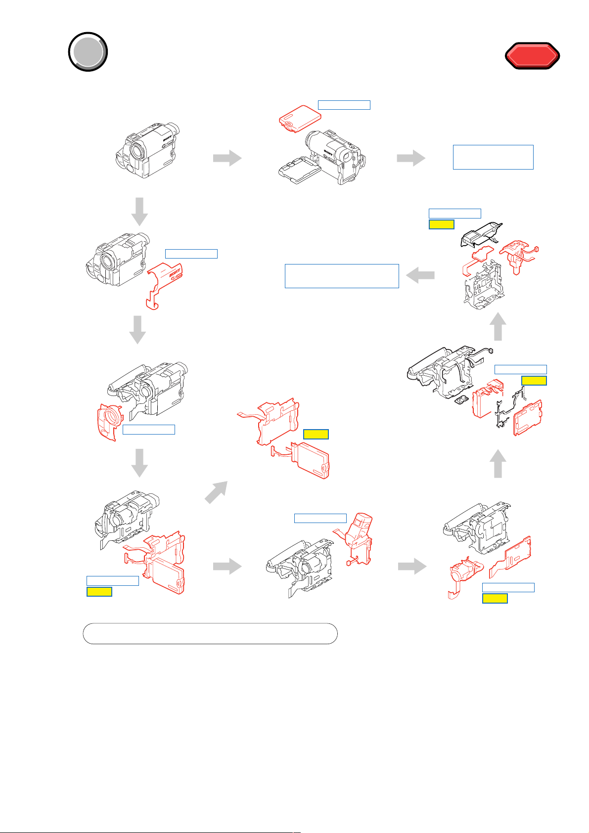
The following flow chart shows the disassembly procedure.
DISASSEMBLY
DISASSEMBLY
SERVICE POSITION TO
CHECK THE VTR SECTION
PD-188 board
service position
DISASSEMBLY
HELP
HELP
HELP
DISASSEMBLY
DISASSEMBLY
HELP
PROCEDURE OF REMOVING MECHANISM DECK
1 2-2. CABINET (R) COVER (39E) ASSEMBLY ........
2 2-3. F PANEL SECTION ........................................
3 2-5. CABINET (R) SECTION ...................................
4 2-10. BT PANEL/EVF SECTION ...........................
5 2-14. VA-118 BOARD, LENS SECTION ................
6 2-16. MECHANISM DECK, VC-311 BOARD (1) ....
7 2-17. MECHANISM DECK, VC-311 BOARD (2) ....
(page 2-4)
(page 2-5)
(page 2-7)
(page 2-11)
(page 2-15)
(page 2-16)
(page 2-17)
DISASSEMBLY
HELP
DISASSEMBLY
HELP
DISASSEMBLY
DISASSEMBLY
HELP
2-1

DCR-TRV12E/TRV14E/TRV19/TRV19E
)
NOTE: Follow the disassembly procedure in the numerical order given.
[CONNECTION OF EQUIPMENT]
LANC jack
AC IN
AC power
adaptor
DC-IN connector
CPC-7 jig
(J-6082-382-A)
CPC lid
Screw
×
4),
(M1.7
lock ace, p2
Adjustment remote
commander (RM-95
2-2

2-1. P CABINET (C) ASSEMBLY
Caution
Rotation of the LCD panel has limitation due to its
hinge in this model. Excessive force to rotate the
LCD panel damages the hinge. Follow the precaution
below.
Opening and closing of LCD panel must be performed
only in the state that the LCD panel is completely in
parallel (perpendicular) with the main body of the
recorder.
3
Screw
(M1.7 × 4),
lock ace, p2
DCR-TRV12E/TRV14E/TRV19/TRV19E
4
2
Turn the LCD panel
1
Open the
LCD panel
7
Four claws
5
Screw
(M1.7
lock ace, p2
8
P cabinet (C) assembly
LCD panel
×
4),
Turn the
When you want to rotate the LCD panel, rotate it after
the LCD panel is opened in its fully opened position.
[PD-188 BOARD SERVICE POSITION]
PD-188 board
PD-188
6
Two tapping screws
×
(M1.7
5)
Adjustment remote
commander (RM-95)
PD-188
2-3
AC power
adaptor
CPC-7 jig
(J-6082-382-A)
AC IN

DCR-TRV12E/TRV14E/TRV19/TRV19E
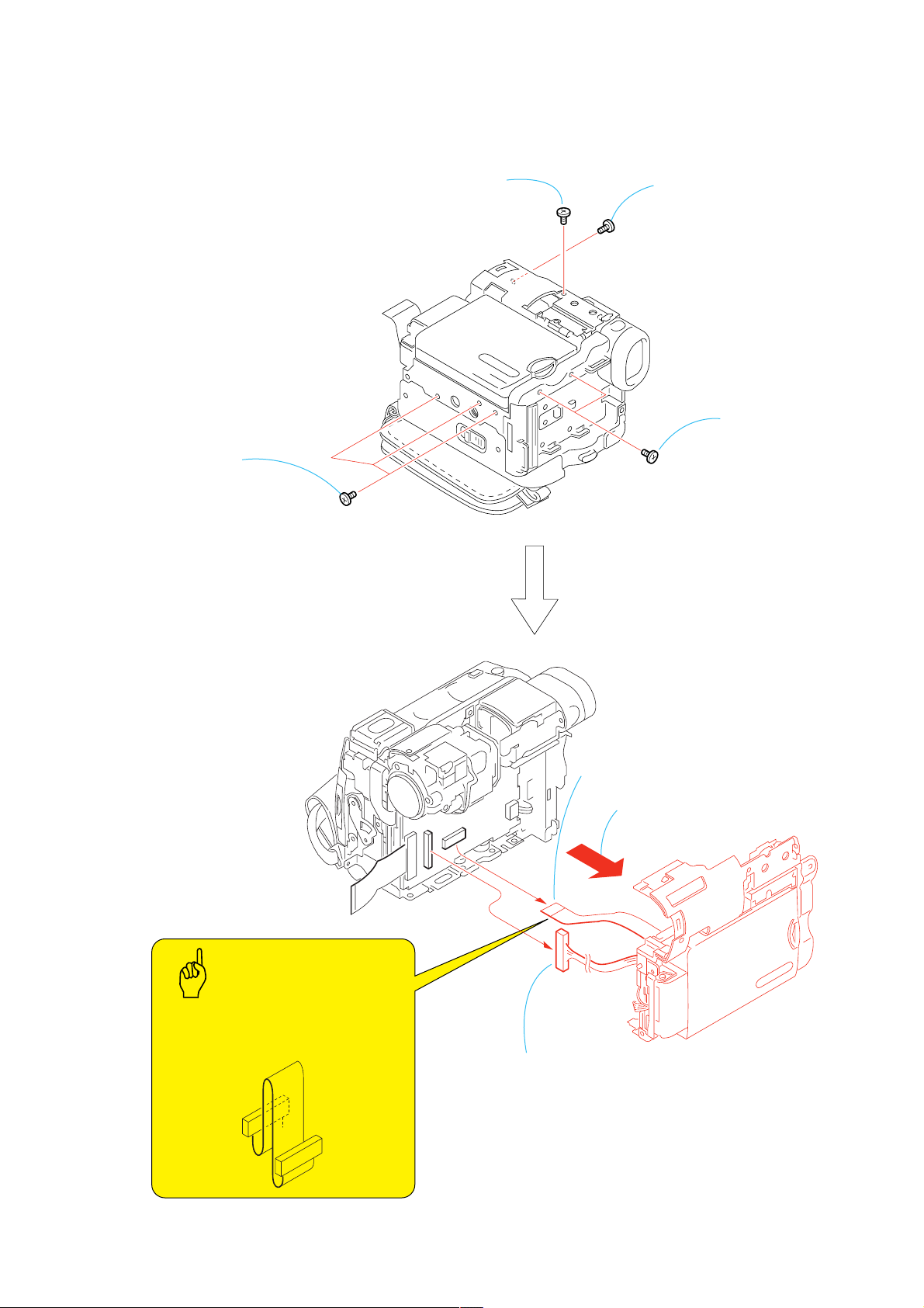
2-2. CABINET (R) COVER (39E) ASSEMBLY
1
Two screws
(M1.7 × 6),
lock ace, p2
Caution
5
Raise the Finder in the
direction of the arrow
6
Screw
(M1.7 × 3),
lock ace, p2
4
Two screws
(M1.7 × 3),
lock ace, p2
3
Open the LCD panel
When remove the Cabinet R cover
(39E) to the main body, remove the
Cabinet R cover (39E) while raising,
so that A marked portion must not
be damaged.
A
2
Screw
(M1.7 × 3),
lock ace, p2
Caution
Insert the projected portion of the Cabinet R cover (40E)
assembly into the cabinet L side of the the chassis.
The projected
portion
The chassis
The cabinet L side
9
Remove the
projected part
8
Remove the
projected part
q;
Push the Cabinet R cover (39E)
in the direction of the arrow to
remove the three claws.
Claws
7
Close the LCD panel
2-4
qa
Pull out the Cabinet R cover (39E)
from the main body.
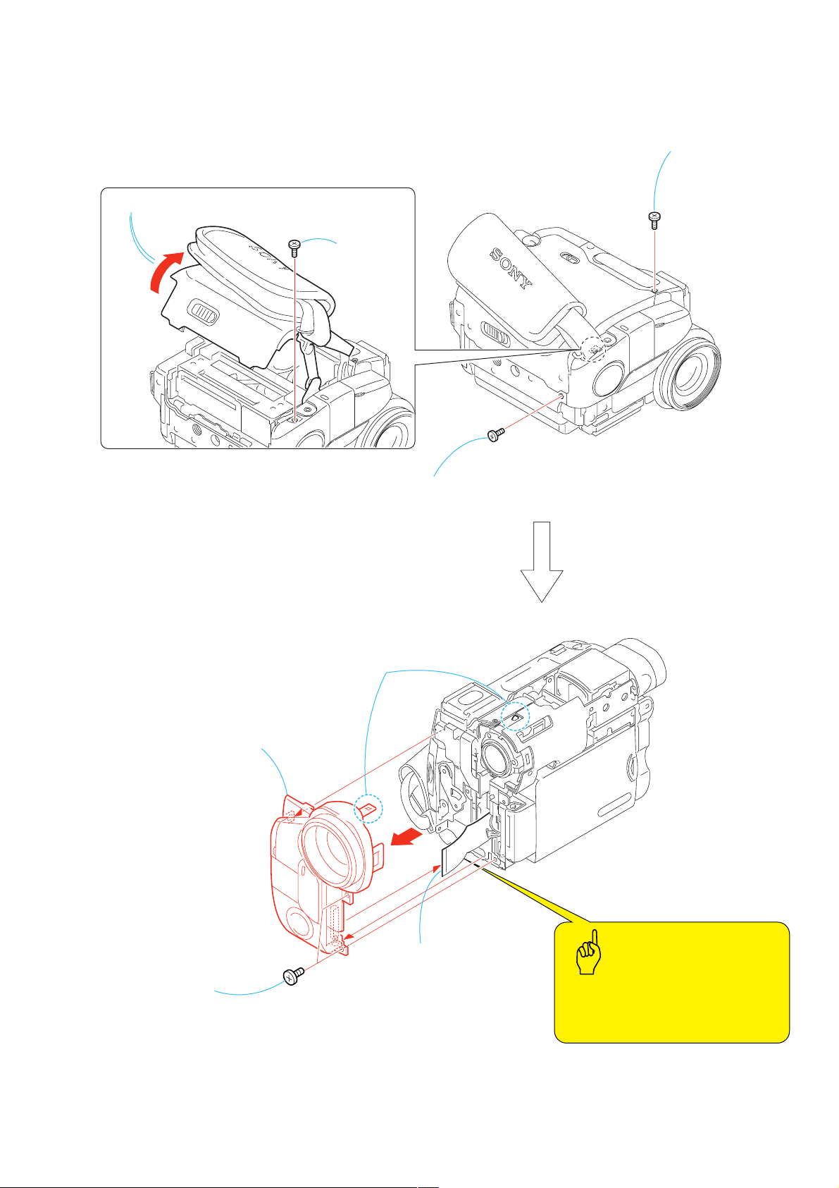
2-3. F PANEL SECTION
3
Open the Cassette lid
4
Screw
(M1.7 × 4),
lock ace, p2
DCR-TRV12E/TRV14E/TRV19/TRV19E
1
Screw
(M1.7 × 4),
lock ace, p2
7
Remove the F panel section
in the direction of the arrow
6
Remove the claw
2
Screw
(M1.7 × 4),
lock ace, p2
5
Two screws
(M1.7 × 4),
lock ace, p2
8
FP-621 flexible board
(36P)
2-5
Caution
The FP-621 flexible board may be damaged
if you remove the F panel section forcibly.
Be very careful not to damage the flexible
board.
DCR-TRV12E/TRV14E/TRV19/TRV19E
s
2-4. MA-421 BOARD
8
Remove the MA-421 board in the way of twisting it
in the direction of the arrow
9
HP sheet
6
Microphone
5
Microphone retainer
3
Microphone (4P)
4
Tapping screw
(M1.7 × 5)
2
MA cover,
MA cover cushion
q;
MA-421 board
7
Two tapping screws
(M1.7 × 5)
Caution
When installing the MA-421 board, attach the HP sheet so that
the metal terminals of the headphones jack are hidden (insulated)
by the HP sheet.
Metal terminal part
Headphone jack
HP sheet
1
Three tapping screw
(M1.7 × 5)
2-6
2-5. CABINET (R) SECTION
4
Three screws
(M1.7 × 4),
lock ace, p2
2
Screw
(M1.7 × 4),
lock ace, p2
DCR-TRV12E/TRV14E/TRV19/TRV19E
1
Screw
(M1.7
lock ace, p2
×
4),
3
Two screws
(M1.7 × 4),
lock ace, p2
Caution
When install the Cabinet R section to the
main body, install the FP-618 flexible board
as shown in the illustration.
6
FP-618 flexible board (16P)
7
Herness (PV-140)
(20P)
5
Remove the Cabinet R section
in the direction of the arrow
2-7

DCR-TRV12E/TRV14E/TRV19/TRV19E
s
2-6. LCD SECTION
Caution
Attach the Tape (A) as shown in the illustration.
Tape (A)
1
Tape (A)
6
5
Cabinet R section
LCD section
4
Two tapping screw
(M1.7 × 5)
2
Harness (PV-140)
(4P)
3
FP-626 flexible board
(6P)
2-7. CK-129 BOARD, CONTROL SWITCH BLOCK (CF-CX4000)
3
Control switch block
(CF-CX4000)
6
Loud speaker (1.6CM)
5
Speaker retainer
assembly
4
Two tapping screws
(M1.7
× 3.
5)
7
Two tapping screws
(M1.7
× 3.
5)
q;
CK-129 board
9
FP-618 flexible board
(16P)
2
Screw
(M1.7 × 2.5),
lock ace, p2
1
Control switch block
(CF-CX4000) (6P)
8
Cabinet (R) assembly
2-8

2-8. PD-188 BOARD, LCD UNIT
PD-188
PD-188
2
Two screws
(M1.7
×
4),
lock ace, p2
3
Four claws
4
P cabinet (C)
assembly (M)
5
Harness (PV-140)
(20P, 40P)
1
Tapping screw
(M1.7
×
5)
When remove the Harness (PV-140),
be careful to damage the Harness (PV-140).
8
LCD insulating sheet (40)
qg
Back light
qh
Panel frame (40)
qj
PD-188 board
6
Screw
(M1.7
×
2.5),
lock ace, p2
q;
Dowel
qa
Two claws
qs
Liquid crystal
indicator module
(24P, 6P)
qd
Liquid crystal
indicator module
7
P cabinet (M) (40) assembly
9
LCD cushion (T)
qf
Back light (10P)
Caution
DCR-TRV12E/TRV14E/TRV19/TRV19E
2-9

DCR-TRV12E/TRV14E/TRV19/TRV19E
2
2-9. HINGE (40) ASSEMBLY
Caution
1
Screw
(M1.7 × 4),
lock ace, p2
3
counterclockwise by 90 degrees
in the direction of the arrow
2
A
2
Rotate to the "A" marked portion
counterclockwise by 90 degrees
3
3
Rotate the "B" marked portion
B
Rotation of the LCD panel has limitation due to its hinge
in this model. Excessive force to rotate the LCD panel
damages the hinge.
(Refer to "Caution"of 2.1 Pcabinet assembly.)
Caution
If the FP-626 flexible board is removed once, the
adhesion strength of a double-sided tape decreases.
Use the new FP-626 flexible board at the time of an
assembly.
8
Remove the FP-626 flexible board
that is attached by the doble-sided tape
Dowel for setting
the position
4
Three claws
7
Hinge cover (M) (40)
Hinge (40) assembly
6
Screw
(M1.7 × 4),
lock ace, p
9
Harness (PV-140)
5
Hinge cover (C) (40)
0
Hinge (40) assembly
Remove the Harness (PV-140) in the direction
of the arrow
Bend the Harness (PV-140) along with connector
2-10

2-10. BT PANEL/EVF SECTION
1
Screw
×
(M1.7
lock ace, p2
4),
4
FP-619 flexible board
(20P)
DCR-TRV12E/TRV14E/TRV19/TRV19E
5
BT panel/EVF section
2
Two screws
(M1.7 × 4),
lock ace, p2
3
Battery terminal board
(3P)
2-11
DCR-TRV12E/TRV14E/TRV19/TRV19E
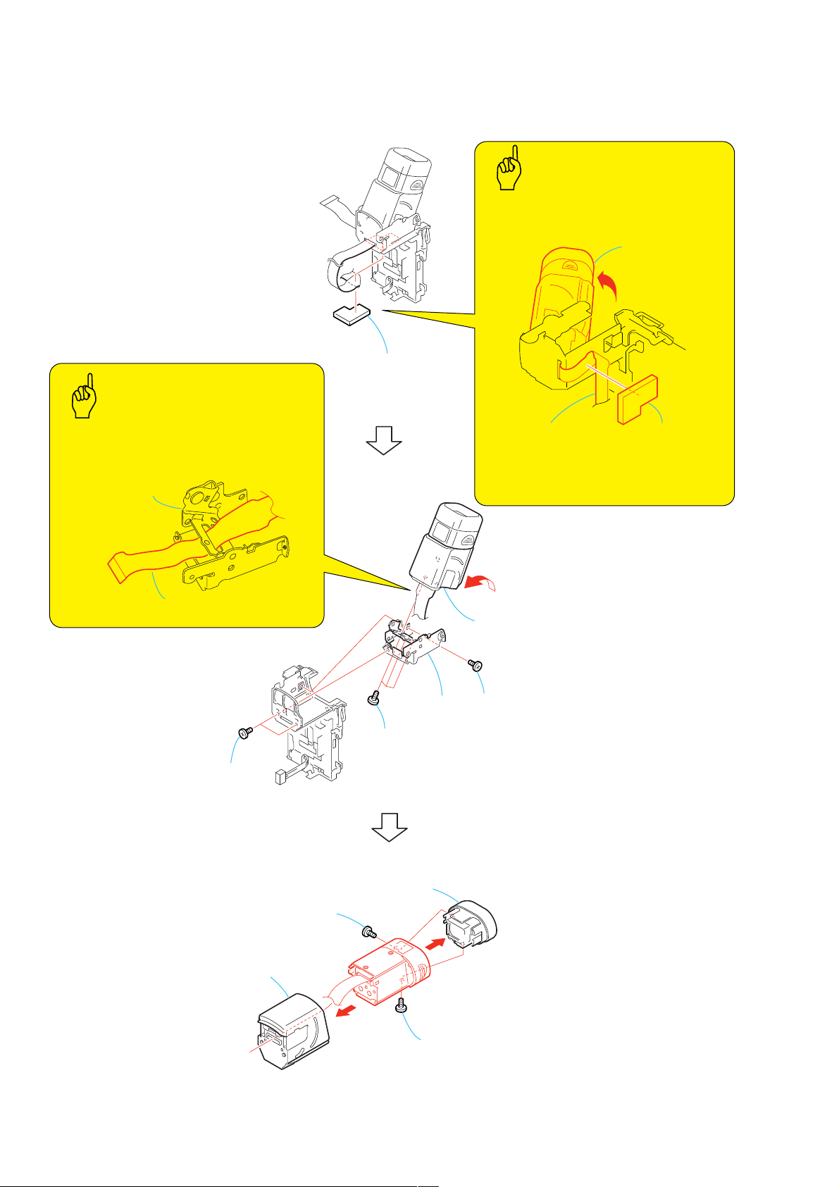
2-11. LB-085 BOARD (REMOVING OF THE EVF)-1
Caution
1
EVF flexible
retainer
Caution
When installing the EVF flexible retainer,
please be sure to install it while the viewfinder
is kept pushed up to attach.
Finder
When installing, pass the FP-619 flexible
board through the hole of the VF hinge assembly
as shown in the illustration.
VF hinge assembly
FP-619 flexible board
3
Two screws
(M1.7 × 2.5),
lock ace, p2
6
VF hinge
assembly
5
Three screws
(M1.7
lock ace, p2
×
4),
FP-619 flexible board
When installing the EVF flexible retainer, fold
the FP-619 flexible board as shown in the
illustration.
FP-619 flexible board
2
Raise the Finder in the
direction of the arrow
4
Screw
(M1.7 × 2.5),
lock ace, p2
EVF flexible
retainer
7
VF tilt cabinet
9
Screw
(M1.7 × 2.5),
lock ace, p2
q;
Eye cup (40)
assembly
2-12
8
Screw
(M1.7
lock ace, p2
×
2.5),

2-12. LB-085 BOARD (REMOVING OF THE EVF)-2
5
Visiblity knob (40)
DCR-TRV12E/TRV14E/TRV19/TRV19E
VF slide cabinet (upper) assembly
To raise the VF slide cabinet (upper)
assembly, insert a flat head
(-) screwdriver into the position shown
by the arrow.
VF slide cabinet (upper) assembly
VF slide cabinet (lower)
2
3
Two claws
A
RE-ASSEMBLING THE VF SLIDE CABINET
1
VF slide assembly
4
B
2
A
VF slide cabinet (lower)
6
2
Open the lock of the VF slide cabinet (lower) in the direction of the arrow A,
3
release the two claws of the VF slide cabinet (upper) assembly,
4
while slanting the VF slide cabinet (upper) in the direction of the arrow B,
5
remove the Visibility knob (40) from the VF slide cabinet (lower), and
6
remove the VF slide cabinet (upper) assembly by sliding it in the direction
of the arrow
1
Tapping screw
×
(M1.7
C
C
.
2
Align the dotted portion of the VF slide assembly
with the dotted line of the VF slide cabinet (lower).
3.5)
When re-assembling is completed,
the VF slide cabinet (upper) assembly
and the VF slide cabinet (lower) are
assembled as shown.
VF slide cabinet (upper) assembly
VF slide cabinet (lower)
Visiblity knob (40)
Two claws
VF slide cabinet (lower)
When re-assembling, slide the
Visibility knob (40) to the fully
right-end beforehand.
3
Slide the VF slide cabinet assembly up to
the position in the direction of the arrow
where the two claws are locked.
4
(M1.7 × 3.5)
VF slide cabinet (lower)
Tapping screw
2-13

DCR-TRV12E/TRV14E/TRV19/TRV19E
2-13. LB-085 BOARD (REMOVING OF THE EVF)-3
Two screws
1
(M1.7
lock ace, p2
2
Pull out the VF slide assembly fully
in the direction of the arrow.
VF slide Cabinet (upper) assembly
VF slide assembly, etc.
×
2.5),
Caution
When attach the Sheet (VF),
fold the flexible board of the
LCX032AN-5 as shown in
the illustration.
Flexible board of the
LCX032AN-5
Sheet (VF)
A
3
Slide the VF slide cabinet assembly and others once
to the deep end, then slant them in the direction of
B
6
Remove the LCD cabinet assembly and others from the two dowels and
cut-outs of the VF slide assembly.
5
Screw
(M1.7 × 2.5),
lock ace, p2
VF slide assembly
qa
Lamp guide (40)
the arrow
assembly and finally pull them out in the direction of the
arrow
Two dowels
A
to release the claw portion of the VF slide
B
and remove them.
4
(M1.7 × 2.5),
Cut-outs
lock ace, p2
Screw
7
Sheet (VF)
q;
Cushion LB (40)
Two craws
8
FP-619 flexible board
Projected part
Two craws
2-14
9
LB-085 board
qd
Prism sheet (40)
qs
Illuminator (40)
qg
qf
LCX032AN-5
LCD cabinet assembly
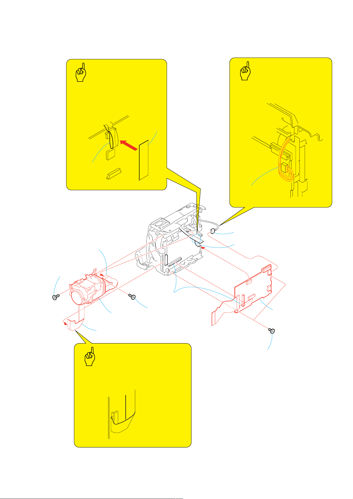
2-14. VA-118 BOARD, LENS SECTION
q;
Lens section
6
Lens device LSV-650E (24P)
Flexible board of the
Lens device LSV-650E
9
Screw
(M1.7 × 2.5),
lock ace, p2
2
Two screws
(M1.7 × 2.5),
lock ace, p2
5
VA-118 board,
FP-621 flexible board
1
Control switch block
(FK-CX4000) (3P)
8
Screw
(M1.7 × 2.5),
lock ace, p2
7
FP-623 flexible board
(14P)
4
FP-620 flexible board
(10P)
3
B to B connector
(100P)
Caution
FP-620 flexible
board
Caution
Tape (A)
When attach the Tape (A), fold the FP-620
flexible board as shown in the illustration.
Caution
When installing, the flexible board of the
Lens device 650E as shown in the illustration.
Harness of the Control
switch block (FK-CX4000)
Fold the harness of the control switch
block (FK-CX4000) toward the board as
shown in the illustration.
DCR-TRV12E/TRV14E/TRV19/TRV19E
2-15
DCR-TRV12E/TRV14E/TRV19/TRV19E
s
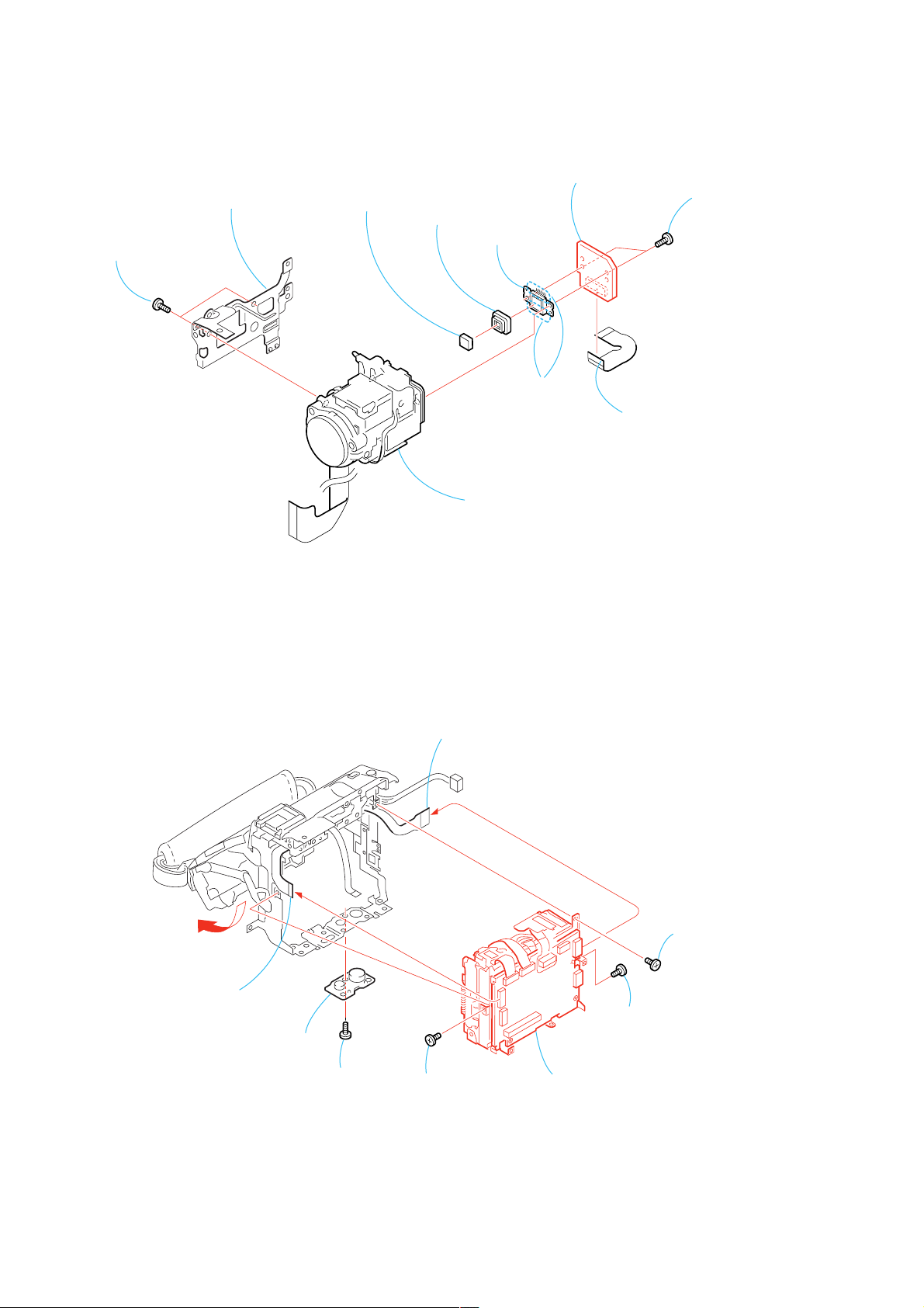
2-15. CD-430 BOARD
2
1
Two tapping screws
(M1.7
×
3.5)
Lens frame (39) assembly
6
optical filter block
7
Seal rubber (W)
8
CCD block
assembly
9
Remove soldering
q;
CD-430 board
3
(14P)
4
Two tapping screw
(M1.7 × 5)
FP-623 flexible board
2-16. MECHANISM DECK, VC-311 BOARD (1)
6
Open the cassette lid
5
Lens device LSV-650E
1
Control switch block (FK-CX4000)
(12P)
3
Screw
(M1.7 × 2.5),
lock ace, p2
2
FP-625 flexible board
(16P)
8
Screw
7
Screw
(M1.7 × 4),
lock ace, p2
5
Screw
(M1.7 × 2.5),
lock ace, p2
2-16
4
(M1.7 × 2.5),
lock ace, p2
9
Mechanism deck,
VC-311 board
Screw

2-17. MECHANISM DECK, VC-311 BOARD (2)
)
q;
Mechanism deck
DCR-TRV12E/TRV14E/TRV19/TRV19E
1
Flexible board (from the capstan motor)
(27P)
2
Flexible board (from the FP-468 flexible board
(27P)
3
Flexible board (from the drum motor)
(10P)
4
Flexible board (from the video head)
(10P)
6
Claw
7
VC-311board
9
MD frame assembly
2-18. CABINET (G) ASSEMBLY (39V)
4
Cabinet (G) assembly (39V)
8
Four screws
(M1.4 × 1.5)
1
Three tapping screws
(M1.7 × 3.5)
5
Two screws
(M1.7 × 2.5),
lock ace, p2
3
Two screws
×
(M1.7
lock ace, p2
2.5),
2-17
Tapping screw (M1.7
Screw (M1.7
2
Two screws
(M1.7 × 2.5),
lock ace, p2
×
3.5)
×
2.5), lock ace, p2

DCR-TRV12E/TRV14E/TRV19/TRV19E
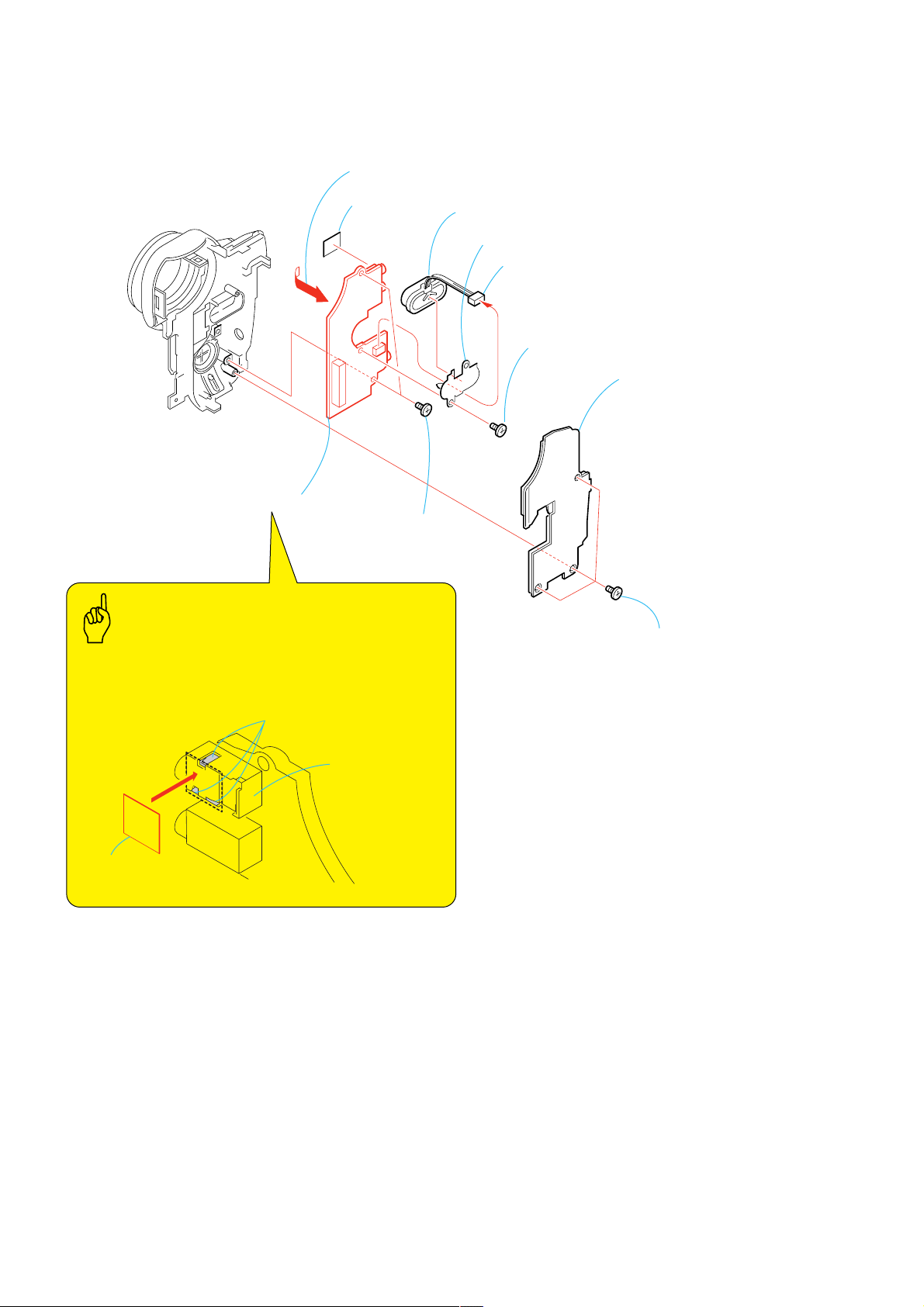
2-19. CONTROL SWITCH BLOCK (FK-CX4000)
4
FK flexible retainer
7
Control switch block
(FK-CX4000)
Caution
When installing, fix the flexible board of the Control switch
block (FK-CX4000) with the FK flexible retainer as shown
in the illustration.
5
Screw
(M1.7 × 4),
lock ace, p2
2
Screw
(M1.7 × 4),
lock ace, p2
1
Screw
(M1.7 × 4),
lock ace, p2
3
Pull and remove the
Cabinet L assembly (40E),
shoe frame, etc.
Flexible cover
6
Remove the Harness of the
control switch block (FK-CX4000)
from the Flexible cover
FK flexible retainer
Flexible board
Caution
When installing, pass harness of the Control switch block
(FK-CX4000) the through the Flexible cover by the
A
marked
Flexible cover
.
A
Harness
2-20. JK-242 BOARD
3
JK-242 board,
FP-625 flexible board
1
Sheet Z
2
Two screws
(M1.7 × 2.5),
lock ace, p2
Caution
Install the Sheet Z as shown in the illustration.
Sheet Z
2-18

DCR-TRV12E/TRV14E/TRV19/TRV19E
)
[SERVICE POSITION TO CHECK THE VTR SECTION]
Connection to Check the VTR Section
To check the VTR section, set the VTR to the “Forced VTR power ON” mode.
Operate the VTR functions using the adjustment remote commander (with the HOLD switch set in the OFF position).
Setting the “Forced VTR Power ON” mode
1) Select page: 0, address: 01, and set data: 01.
2) Select page: 0, address: 10, and set data: 00.
3) Select page: D, address: 10, set data: 02, and
press the PAUSE button of the adjustment remote
commander.
Exiting the “Forced VTR Power ON” mode
1) Select page: 0, address: 01, and set data: 01.
2) Select page: 0, address: 10, and set data: 00.
3) Select page: D, address: 10, set data: 00, and press
the PAUSE button of the adjustment remote commander.
4) Select page: 0, address: 01, and set data: 00.
(To eject the cassette, short the circuit between Pin 4 of IC4101 and GND pattern on VA-118 board for 1 second.)
Monitor TV
Adjustment remote
commander (RM-95)
LANC jack
F panel section
To eject the cassette, short the circuit
between Pin
pattern on VA-118 board for 1 second.
4
of IC4101 and GND
41
IC4101
60
61 80
GND pattern
2140
20
4
1
AUDIO/VIDEO jack
MA-421 board
Extension cable (100P)
(J-6082-352-A)
CN5402
CN4002
IC4101
CN4004
VA-118
VA-118 board
DC-IN jack
Power harness
AC IN
JK-242
CN1002
CN4602
JK-242 board
VC-311
VC-311 board
AC power
adaptor
CN1004
1
Mechanism deck
Need not be connected
16
1
8
9
16
CPC-7 jig
(J-6082-382-A)
Control switch block (FK-CX4000
(J-6082-382-A)
PROCEDURE OF REMOVING MECHANISM DECK
1 2-2. CABINET (R) COVER (39E) ASSEMBLY ........
2 2-3. F PANEL SECTION ........................................
3 2-5. CABINET (R) SECTION ...................................
4 2-10. BT PANEL/EVF SECTION ...........................
5 2-14. VA-118 BOARD, LENS SECTION ................
6 2-16. MECHANISM DECK, VC-311 BOARD (1) ....
7 2-17. MECHANISM DECK, VC-311 BOARD (2) ....
(page 2-4)
(page 2-5)
(page 2-7)
(page 2-11)
(page 2-15)
(page 2-16)
(page 2-17)
2-19

DCR-TRV12E/TRV14E/TRV19/TRV19E
2-21. CIRCUIT BOARDS LOCATION
CD-430
JK-242
LB-085
VC-311
MA-421
VA-118
CK-129
PD-188
NAME FUNCTION
CD-430
CK-129
JK-242
LB-085
MA-421
PD-188
VA-118
VC-311
CCD IMAGER
FUNCTION SWITCH
RELAY
EVF, BACKLIGHT
MIC AMP, Y/P SENSOR, V/A IN/OUT
RGB DRIVE, TIMING GENE, BACKLIGHT
RGB DRIVE, HI CONTROL, Y/P SENSOR AMP, POWER IN, CHARGE, CONNECTOR
CAMERA A/D CONV., TIMING GENERATOR, IRIS/FOCUS/ZOOM DRIVE,
DV SIGNAL PROCESS, DV INTERFACE, USB, AUDIO, VIDEO OUT, REC/PB AMP, EVR,
DRUM/CAPSTAN/LOADING DRIVE, CAMERA/MECHA CONTROL, AUDIO I/O, A/D,
D/A CONV., CONNECTOR, DC SUPPLY
2-20

DCR-TRV12E/TRV14E/TRV19/TRV19E
K
2-22. FLEXIBLE BOARDS LOCATION
The flexible boards contained in the mechanism deck and that in the lens device are not shown.
CONTROL SWITCH BLOCK
(FK-CX4000)
FP-620
CONTROL SWITCH BLOC
(CF-CX4000)
FP-618
FP-621
FP-626
FP-625
FP-623
FP-619
2-21E
 Loading...