

Page 1
DCR-TRV130E
RMT-814
SERVICE MANUAL
SERVICE MANUALSERVICE MANUAL
Level 1
Ver 1.0 2001. 01
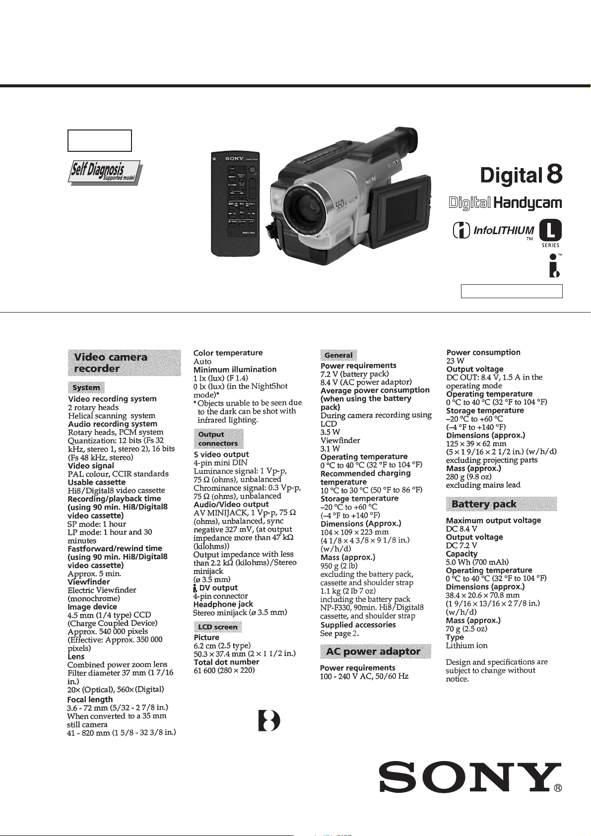
SPECIFICATIONS
AEP Model
UK Model
M2000 MECHANISM
DIGITAL VIDEO CAMERA RECORDER
Page 2
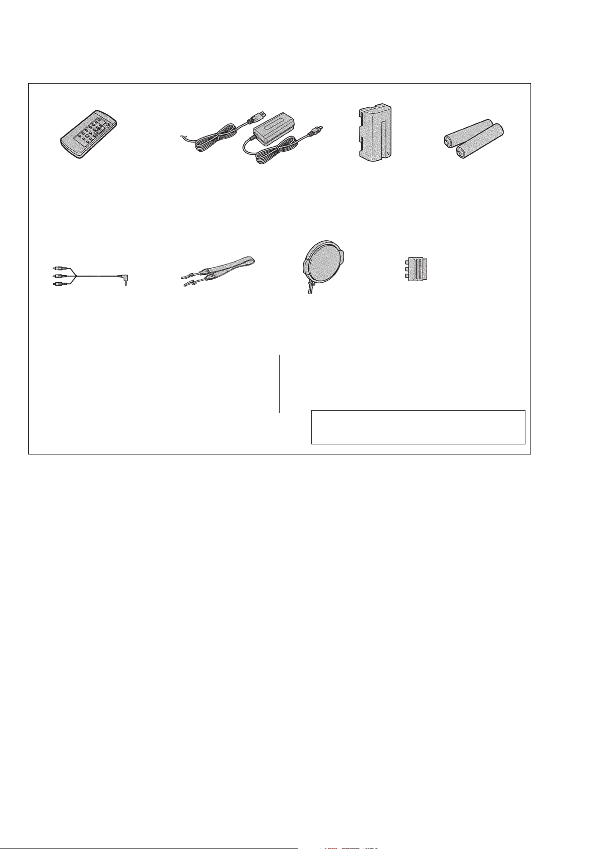
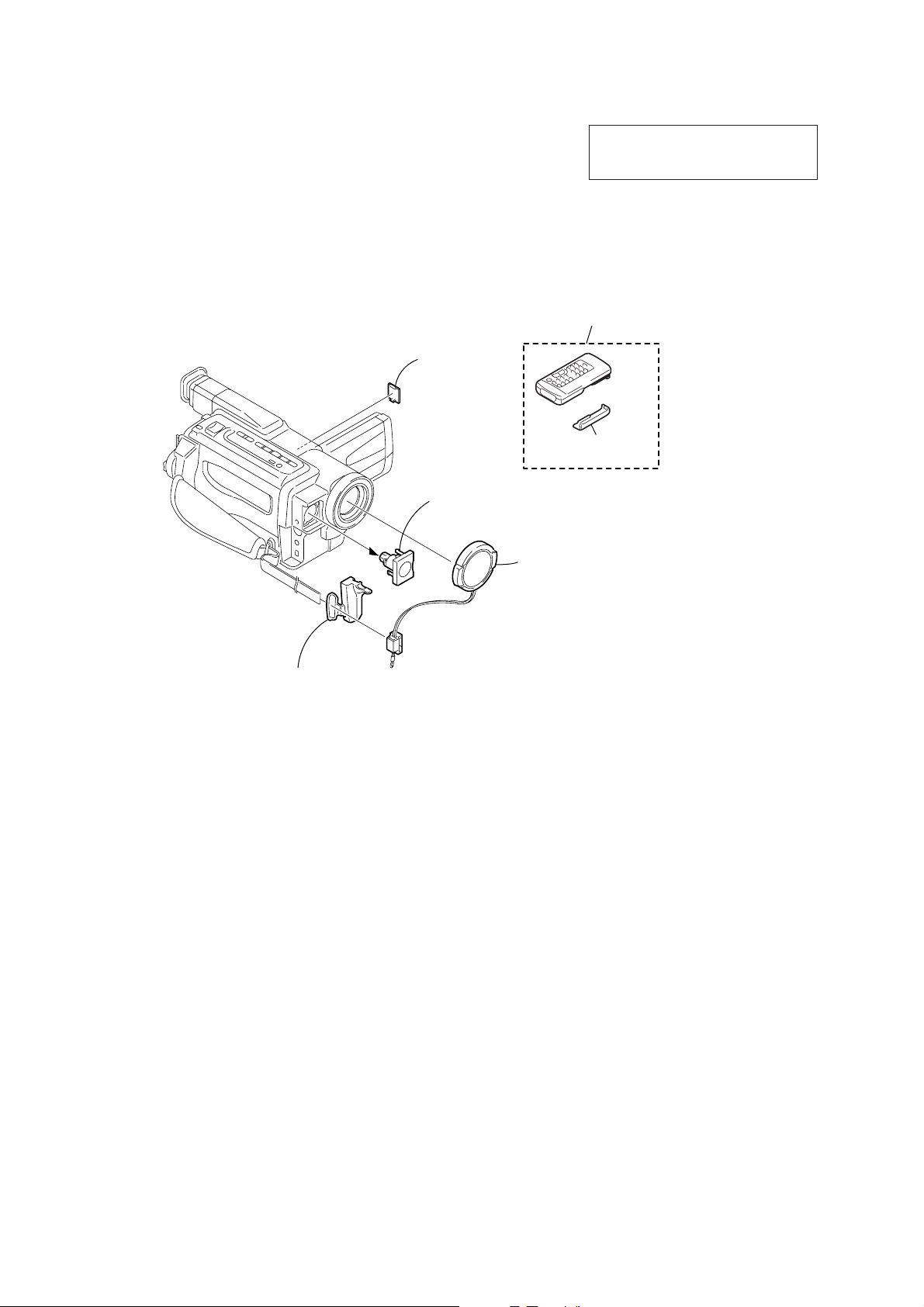
Checking supplied accessories.
Make sure that the following accessories are supplied with your camcorder.
Wireless Remote Commander (1)
RMT-814
1-475-141-61
A/V connecting cable (1.5m) (1)
1-765-080-11
AC-L10A/L10B/L10C
AC power adaptor (1)
0
1-475-599-11
Power cord (1) (AEP only)
0
1-769-608-11
Power cord (1) (UK only)
0
1-783-374-11
Shoulder strap (1)
3-987-015-01
Other accessories
3-065-652-11 OPERATING INSTRUCTIONS (ENGLISH/RUSSIAN)
3-065-652-21 OPERATING INSTRUCTIONS (FRENCH/GERMAN)(AEP)
3-065-652-31 OPERATING INSTRUCTIONS (ENGLISH/DUTCH)(AEP)
3-065-652-41OPERATING INSTRUCTIONS (SPANISH/PORTUGUESE)
3-065-652-51 OPERATING INSTRUCTIONS (ITALIAN/GREEK)(AEP)
(AEP)
NP-F330
battery pack (1)
(A-7094-141-A)
Lens cap (1)
X-3949-376-1
3-065-652-61 OPERATING INSTRUCTIONS (ENGLISH/SWEDISH)(AEP)
3-065-652-71 OPERATING INSTRUCTIONS (FINNISH/DANISH)(AEP)
3-065-652-81 OPERATING INSTRUCTIONS (POLISH/CZECH)(AEP)
3-065-652-91 OPERATING INSTRUCTIONS (SLOVAKIAN/HUNGARIAN)
Note : The components identified by mark 0 or dotted
line with mark 0 are critical for safety.
Replace only with part number specified.
21-pin adaptor (1)
1-573-291-11
Size AA (R6) battery for
Remote Commander (2)
(not supplied)
(AEP)
SAFETY-RELATED COMPONENT WARNING!!
COMPONENTS IDENTIFIED BY MARK 0 OR DOTTED LINE WITH
MARK 0 ON THE SCHEMATIC DIAGRAMS AND IN THE PARTS
LIST ARE CRITICAL TO SAFE OPERATION. REPLACE THESE
COMPONENTS WITH SONY PARTS WHOSE PART NUMBERS
APPEAR AS SHOWN IN THIS MANUAL OR IN SUPPLEMENTS
PUBLISHED BY SONY.
SAFETY CHECK-OUT
After correcting the original service problem, perform the following
safety checks before releasing the set to the customer.
1. Check the area of your repair for unsoldered or poorly-soldered
connections. Check the entire board surface for solder splashes
and bridges.
2. Check the interboard wiring to ensure that no wires are
"pinched" or contact high-wattage resistors.
3. Look for unauthorized replacement parts, particularly
transistors, that were installed during a previous repair . Point
them out to the customer and recommend their replacement.
4. Look for parts which, through functioning, show obvious signs
of deterioration. Point them out to the customer and
recommend their replacement.
5. Check the B+ voltage to see it is at the values specified.
6. Flexible Circuit Board Repairing
• Keep the temperature of the soldering iron around 270˚C
during repairing.
• Do not touch the soldering iron on the same conductor of the
circuit board (within 3 times).
• Be careful not to apply force on the conductor when soldering
or unsoldering.
— 2 —
Page 3

TABLE OF CONTENTS
SERVICE NOTE
1. POWER SUPPLY DURING REPAIRS ·····························4
2. TO TAKE OUT A CASSETTE WHEN NOT EJECT
(FORCE EJECT) ································································4
SELF-DIAGNOSIS FUNCTION
1. Self-diagnosis Function ······················································5
2. Self-diagnosis Display························································ 5
3. Service Mode Display ························································ 5
3-1. Display Method ·································································· 5
3-2. Switching of Backup No. ··················································· 5
3-3. End of Display···································································· 5
4. Self-diagnosis Code Table ·················································· 6
1. MAIN PARTS
1. ORNAMENTAL PARTS···················································· 8
2. DISASSEMBLY································································· 9
2-1. VIDEO LIGHT································································· 10
2-2. LCD SECTION (PD-131 BOARD) ································· 10
2-3. FRONT PANEL SECTION (MI-041 BOARD) ··············· 11
2-4. CABINET (L) SECTION················································· 11
2-5. CABINET (R) SECTION, CONTROL SWITCH
BLOCK (CF-1000)··························································· 12
2-6. EVF SECTION (VF-129 BOARD)·································· 13
2-7. BATTERY PANEL SECTION
(BATTERY TERMINAL BOARD) ································· 14
2-8. LENS SECTION ······························································ 14
2-9. VC-256 BOARD ······························································ 15
2-10. MECHANISM DECK······················································ 15
2-11. HINGE SECTION···························································· 16
3. REPAIR PARTS LIST······················································ 17
3-1. EXPLODED VIEWS ······················································· 17
3-1-1.OVERALL SECTION······················································ 17
3-1-2.CABINET (L) SECTION················································· 18
3-1-3.EVF SECTION································································· 19
3-1-4.LENS SECTION ······························································ 20
3-1-5.CABINET (R) SECTION ················································21
3-1-6.LCD SECTION ································································ 22
Superimposing a title ······························································ 36
Making your own titles ··························································· 36
Using the built-in light····························································37
Advanced Playback Operations
Playing back a tape with picture effects ································· 38
Playing back a tape with digital effects ·································· 38
Enlarging images recorded on tapes –Tape PB ZOOM··········39
Quickly locating a scene using the zero set memory function ·····
Searching a recording by date –Date search··························· 40
Searching for a photo –Photo search/Photo scan···················· 40
Editing
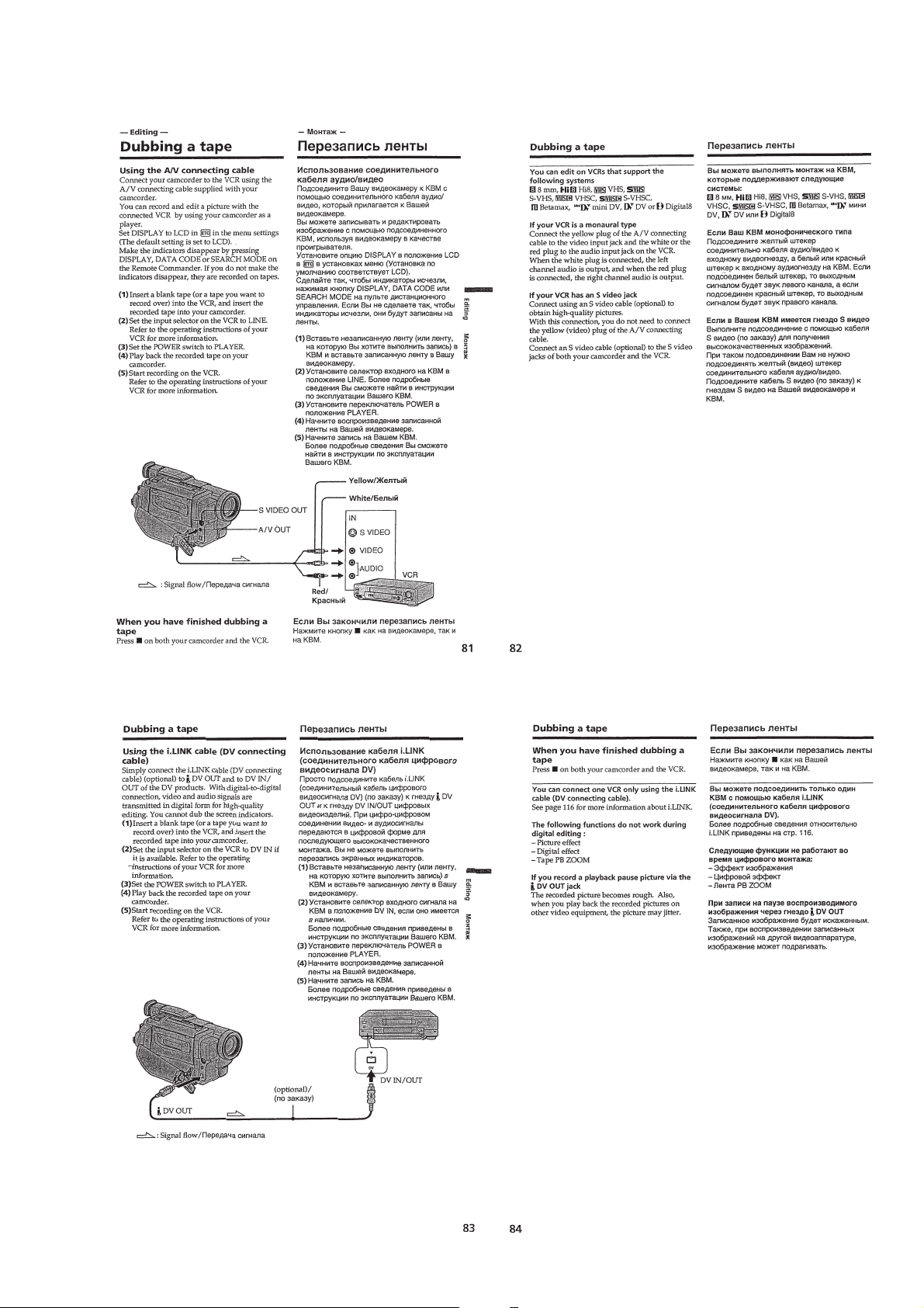
Dubbing a tape ········································································ 41
Customizing Y our Camcorder
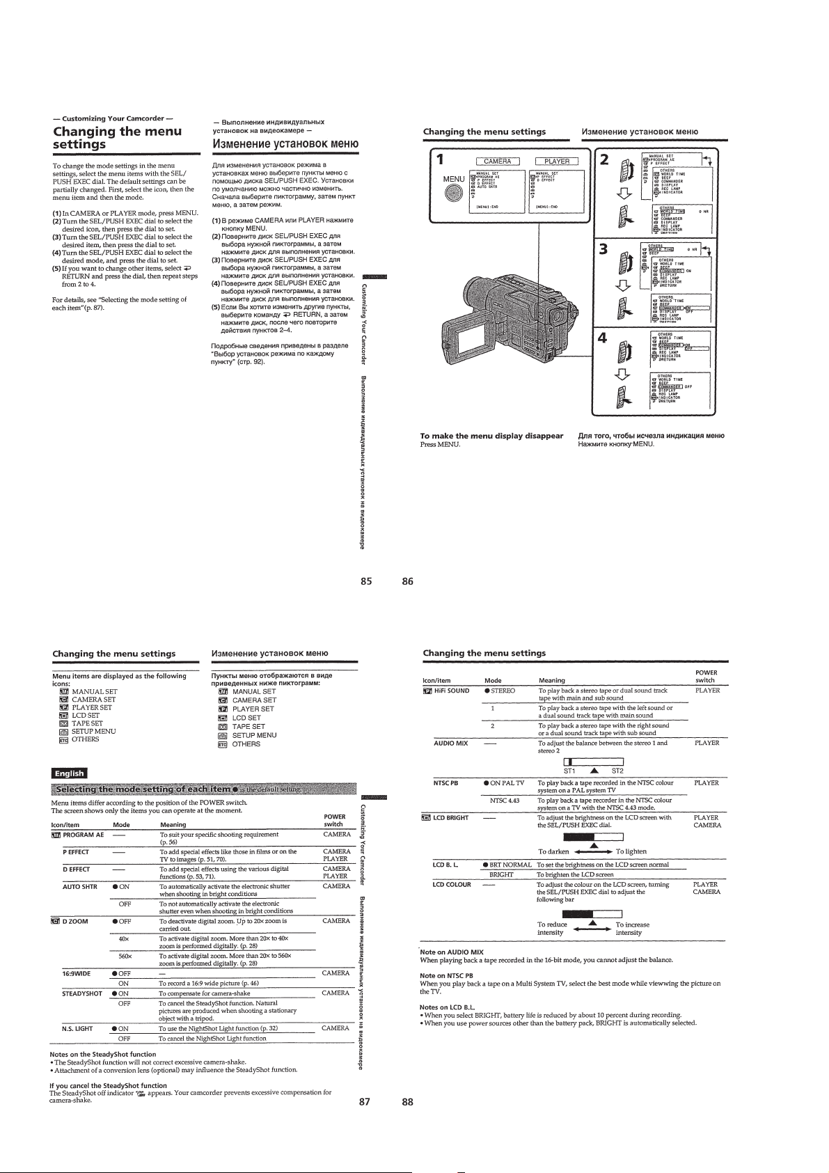
Changing the menu settings····················································42
Troubleshooting
Tupes of trouble and their solutions ······································· 43
Self-diagnosis display ····························································· 44
Warning indicators and messages ··········································· 45
Additional Information
About video cassettes ····························································· 45
About the “InfoLITHIUM” battery pack································ 46
About i.LINK·········································································· 46
Using your camcorder abroad················································· 47
Maintenance information and precautions······························ 47
Quick Reference
Identifying the parts and controls ··········································· 49
39
2. GENERAL
Checking supplied accessories ··················································· 23
Quick Start Guide ······································································· 23
Getting started
Using this manual ··································································· 23
Step 1 Preparing the power supply ········································· 24
Installing the battery pack····················································· 24
Charging the battery pack ····················································· 24
Connecting to the mains ······················································· 25
Step 2 Setting the date and time ············································· 25
Step 3 Inserting a cassette······················································· 26
Recording –Basics
Recording a picture································································· 26
Shooting backlit subjects –BACK LIGHT ··························· 28
Shooting in the dark –NightShot/Super NightShot ·············· 28
Checking the recording –END SEARCH····························· 29
Playback –Basics
Playing back a tape ································································· 29
Viewing the recording on TV ················································· 31
Advanced Recording Operations
Recording a still image on a tape –Tape Photo recording ······ 31
Using the wide mode ······························································ 32
Using the fader function ························································· 32
Using special effects –Picture effect······································· 33
Using special effects –Digital effect·······································34
Using the PROGRAM AE function ········································ 34
Adjusting the exposure manually ··········································· 35
Focusing manually··································································35
— 3 —
Page 4
SERVICE NOTE
1. POWER SUPPLY DURING REPAIRS
In this unit, about 10 seconds after power is supplied (8.4V) to the battery terminal using the service power code (J-6082-223-A), the power
is shut off so that the unit cannot operate.
These following two methods are available to prevent this. Take note of which to use during repairs.
Method 1.
Use the DC IN terminal. (Use the AC power adaptor.)
Method 2.
Connect the adjustment remote commander RM-95 (J-6082-053-B) to the LANC jack, and set the HOLD switch to the “ADJ” side.
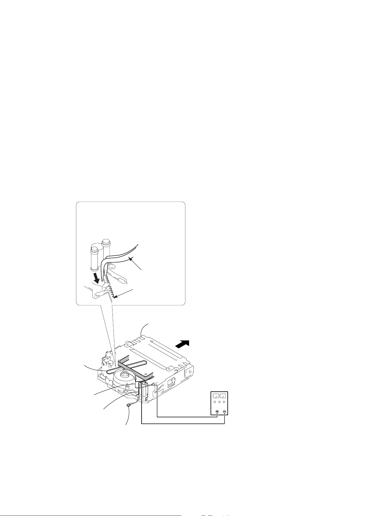
2. TO TAKE OUT A CASSETTE WHEN NOT EJECT (FORCE EJECT)
1 Refer to 2-3. to remove the front panel section.
2 Refer to 2-4. to remove the cabinet (L) section.
3 Refer to 2-5. to remove the cabinet (R) section.
4 Open the control switch block (FK-1000).
5 Disconnect CN4401 (2P) of VC-256 board.
6 Add +5V from the DC POWER SUPPLY and unload with a pressing the cassette compertment.
7
Pull the timing belt in the direction of
arrow
the cassette compartment (take care
not to damage) to adjust the bending
of a tape.
A
Timing belt
Adjust the bending
of a tape
Loading
motor
A
with a pincette while pressing
Pincette
Timing belt
Press the cassette compartment not
to rise the cassette compartment
8
Let your hold the cassette
compartment and rise the cassette
compartment to take out a cassette.
DC power supply
(+5V)
Disconnect CN4401 of
VC-256 board
— 4 —
Page 5
SELF-DIAGNOSIS FUNCTION
1. Self-diagnosis Function
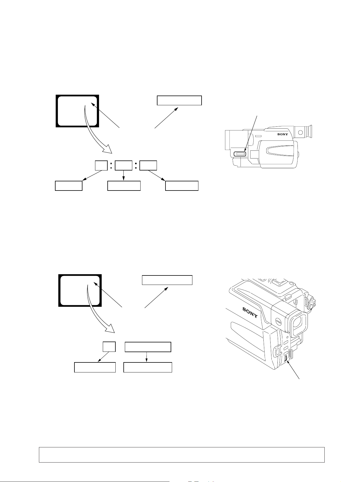
When problems occur while the unit is operating, the self-diagnosis
function starts working, and displays on the viewfinder or LCD or
Display window what to do. This function consists of two display;
self-diagnosis display and service mode display.
Details of the self-diagnosis functions are provided in the Instruction
manual.
Viewfinder or LCD Display window
C : 3 1 : 1 1
Repaired by:
C : Corrected by customer
H : Corrected by dealer
E : Corrected by service
engineer
Blinks at 3.2Hz
C
Indicates the appropriate
step to be taken.
E.g.
31 ....Reload the tape.
32 ....Tur n o n power again.
3 1
Block
1 1
C : 3 1 : 11
Detailed Code
Refer to page 6 and 7.
Self-diagnosis Code Table.
2. Self-diagnosis Display
When problems occur while the unit is operating, the counter of the
viewfinder or LCD or Display window shows a 4-digit display
consisting of an alphabet and numbers, which blinks at 3.2 Hz. This
5-character display indicates the “repaired by:”, “block” in which
the problem occurred, and “detailed code” of the problem.
Display window
3. Service Mode Display
The service mode display shows up to six self-diagnosis codes shown in the past.
3-1. Display Method
While pressing the “STOP” key, set the switch from OFF to “VCR or PLAYER”, and continue pressing the “STOP” key for 5 seconds
continuously. The service mode will be displayed, and the counter will show the backup No. and the 5-character self-diagnosis codes.
Viewfinder or LCD
[3] C : 3 1 : 1 1
Lights up
[3]
Backup No.
Order of previous errors
C : 3 1 : 1 1
Self-diagnosis Codes
3-2. Switching of Backup No.
By rotating the control dial, past self-diagnosis codes will be shown in order. The backup No. in the [] indicates the order in which the
problem occurred. (If the number of problems which occurred is less than 6, only the number of problems which occurred will be shown.)
[1] : Occurred first time [4] : Occurred fourth time
[2] : Occurred second time [5] : Occurred fifth time
[3] : Occurred third time [6] : Occurred the last time
Display window
3 C : 3 1 : 11
Control dial
3-3. End of Display
Turning OFF the power supply will end the service mode display.
Note: The “self-diagnosis display” data will be backed up by the built-in rechargeable lithium battery (CF-1000 block BT101).
When the cabinet (R) assembly is disconnected, the “self-diagnosis displa y” data will be lost by initialization.
— 5 —
Page 6

4. Self-diagnosis Code Table
Self-diagnosis Code
Function
Repaired by:
C
C
C
C
C
C
C
C
C
C
C
C
C
C
C
C
C
C
C
C
C
C
C
C
C
C
C
C
C
Block
04
21
22
31
31
31
31
31
31
31
31
31
31
31
31
31
32
32
32
32
32
32
32
32
32
32
32
32
32
Detailed
Code
00
00
00
10
11
20
21
22
23
30
31
40
41
42
43
44
10
11
20
21
22
23
30
31
40
41
42
43
44
Symptom/State
Non-standard battery is used.
Condensation.
Video head is dirty.
LOAD direction. Loading does not
complete within specified time
UNLOAD direction. Loading does not
complete within specified time
T reel side tape slacking when unloading
S reel
side tape slacking when unloading
T reel fault.
S reel fault.
FG fault when starting capstan.
FG fault during normal capstan operations.
FG fault when starting drum.
PG fault when starting drum.
FG fault during normal drum operations.
PG fault during normal drum operations.
Phase fault during normal drum operations.
LOAD direction loading motor time-
out.
UNLOAD direction loading motor
time-out.
T reel side tape slacking when
unloading.
S reel side tape slacking when
unloading.
T reel fault.
S reel fault.
FG fault when starting capstan.
FG fault during normal capstan
operations.
FG fault when starting drum.
PG fault when starting drum.
FG fault during normal drum
operations.
PG fault during normal drum
operations.
Phase fault during normal drum
operations.
Correction
Use the InfoLITHIUM battery.
Remove the cassette, and insert it again after one hour.
Clean with the optional cleaning cassette.
Load the tape again, and perform operations from the beginning.
Load the tape again, and perform operations from the beginning.
.
Load the tape again, and perform operations from the beginning.
.
Load the tape again, and perform operations from the beginning.
Load the tape again, and perform operations from the beginning.
Load the tape again, and perform operations from the beginning.
Load the tape again, and perform operations from the beginning.
Load the tape again, and perform operations from the beginning.
Load the tape again, and perform operations from the beginning.
Load the tape again, and perform operations from the beginning.
Load the tape again, and perform operations from the beginning.
Load the tape again, and perform operations from the beginning.
Load the tape again, and perform operations from the beginning.
Remove the battery or power cable, connect, and perform
operations from the beginning.
Remove the battery or power cable, connect, and perform
operations from the beginning.
Remove the battery or power cable, connect, and perform
operations from the beginning.
Remove the battery or power cable, connect, and perform
operations from the beginning.
Remove the battery or power cable, connect, and perform
operations from the beginning.
Remove the battery or power cable, connect, and perform
operations from the beginning.
Remove the battery or power cable, connect, and perform
operations from the beginning.
Remove the battery or power cable, connect, and perform
operations from the beginning.
Remove the battery or power cable, connect, and perform
operations from the beginning.
Remove the battery or power cable, connect, and perform
operations from the beginning.
Remove the battery or power cable, connect, and perform
operations from the beginning.
Remove the battery or power cable, connect, and perform
operations from the beginning.
Remove the battery or power cable, connect, and perform
operations from the beginning.
— 6 —
Page 7

Self-diagnosis Code
Function
Repaired by:
E
E
E
E
Block
61
61
62
62
Detailed
Code
00
10
00
01
Symptom/State
Difficult to adjust focus
(Cannot initialize focus.)
Zoom operations fault
(Cannot initialize zoom lens.)
Handshake correction function does not
work well. (With pitch angular velocity
sensor output stopped.)
Handshake correction function does not
work well. (With yaw angular velocity
sensor output stopped.)
Correction
Inspect the lens block focus reset sensor (Pin qs of CN1551 of
VC-256 board) when focusing is performed when the control dial
is rotated in the focus manual mode and the focus motor drive circuit
(IC1551 of VC-256 board) when the focusing is not performed.
Inspect the lens block zoom reset sensor (Pin qf of CN1551 of
VC-256 board) when zooming is performed when the zoom lens is
operated and the zoom motor drive circuit (IC1551 of VC-256
board) when zooming is not performed.
Inspect pitch angular velocity sensor (SE751 of MI-041 board)
peripheral circuits.
Inspect yaw angular velocity sensor (SE752 of MI-041 board)
peripheral circuits.
— 7 —
Page 8
DCR-TRV130E
)
1. MAIN PARTS
Note:
• Follow the disassembly procedure in the numerical order given.
• Items marked “*” are not stocked since they are seldom required for routine service.
Some delay should be anticipated when ordering these items.
• The parts numbers of such as a cabinet are also appeared in this section.
Refer to the parts number mentioned below the name of parts to order.
1. ORNAMENTAL PARTS
CPC lid
3-059-539-11
The components identified by mark 0 or
dotted line with mark 0 are critical for safety.
Replace only with part number specified.
Remote commander (RMT-814
1-475-141-61
Battery case lid
3-742-854-01
Jack cover
3-065-433-01
Video light
1-518-723-21
Lens cap assembly
X-3949-376-1
— 8 —
Page 9
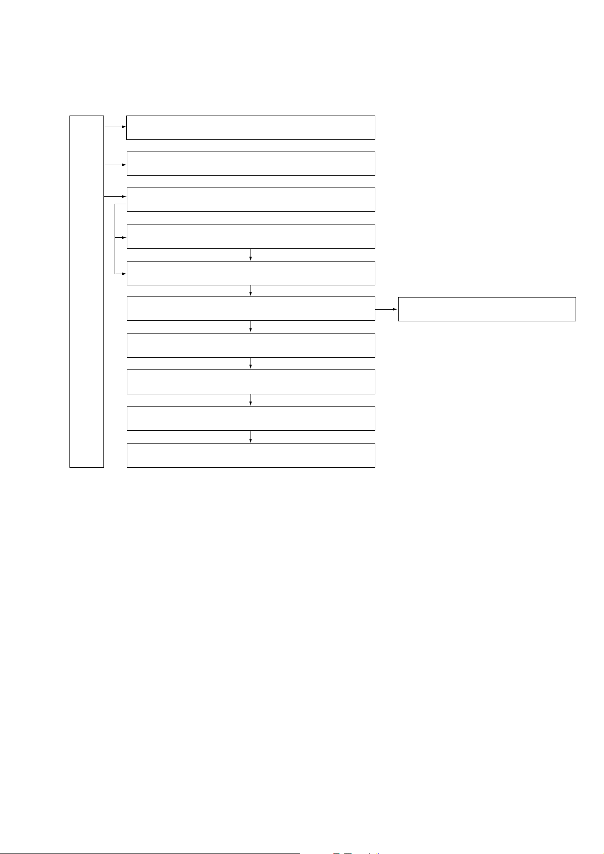
2. DISASSEMBLY
The following flow chart shows the disassembly procedure.
2-1. Video light
2-2. LCD section (PD-131 board)
2-3. Front panel section (MI-041 board)
2-4. Cabinet (L) section
2-5. Cabinet (R) section, Control switch block (CF-1000)
DCR-TRV130E
2-6. EVF section (VF-129 board)
2-7, Battery panel section (Battery terminal board)
2-8, Lens section
2-9. VC-256 board
2-10. Mechanism deck
2-11. Hinge section
— 9 —
Page 10
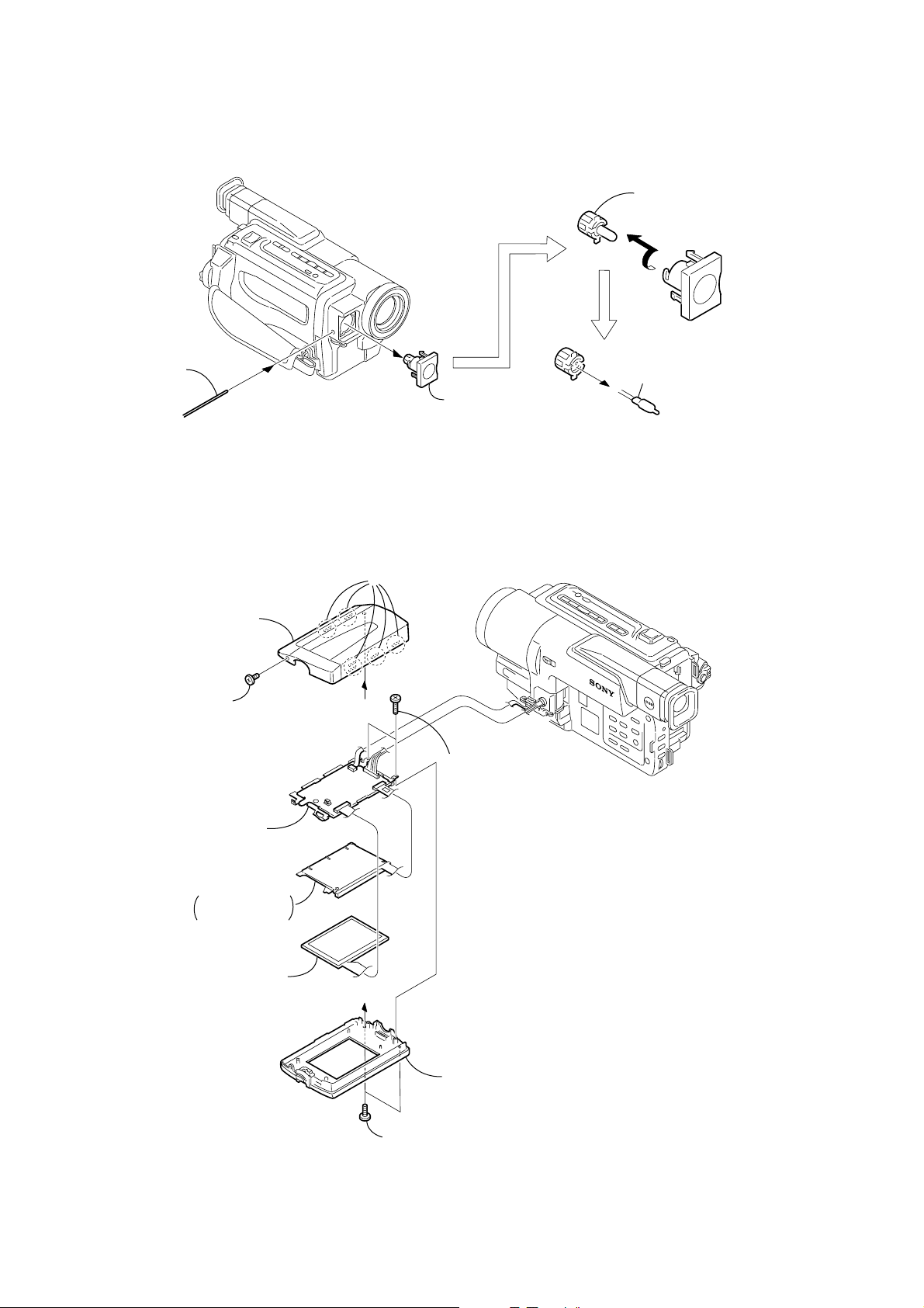
NOTE: F ollo w the disassembly procedure in the numerical order given.
n
2-1. VIDEO LIGHT
1
Push in the dent
inside hole with
wire tip.
2
Video light
2-2. LCD SECTION (PD-131 BOARD)
3
Remove in the directio
of the arrow A.
A
4
Halogen lamp
4
P cabinet C
2
MI screw
(M2
×
4) (H)
9
PD-131 board,
Panel frame
8
Back light
Cold cathode
fluorescent tube
7
Liquid crystal
indicator module
PD-131
3
A
A
Five claws
5
T wo tapping
screws (B2
×
7)
6
1
T wo tapping
screws (B2
— 10 —
P cabinet M assembly
×
5)
Page 11
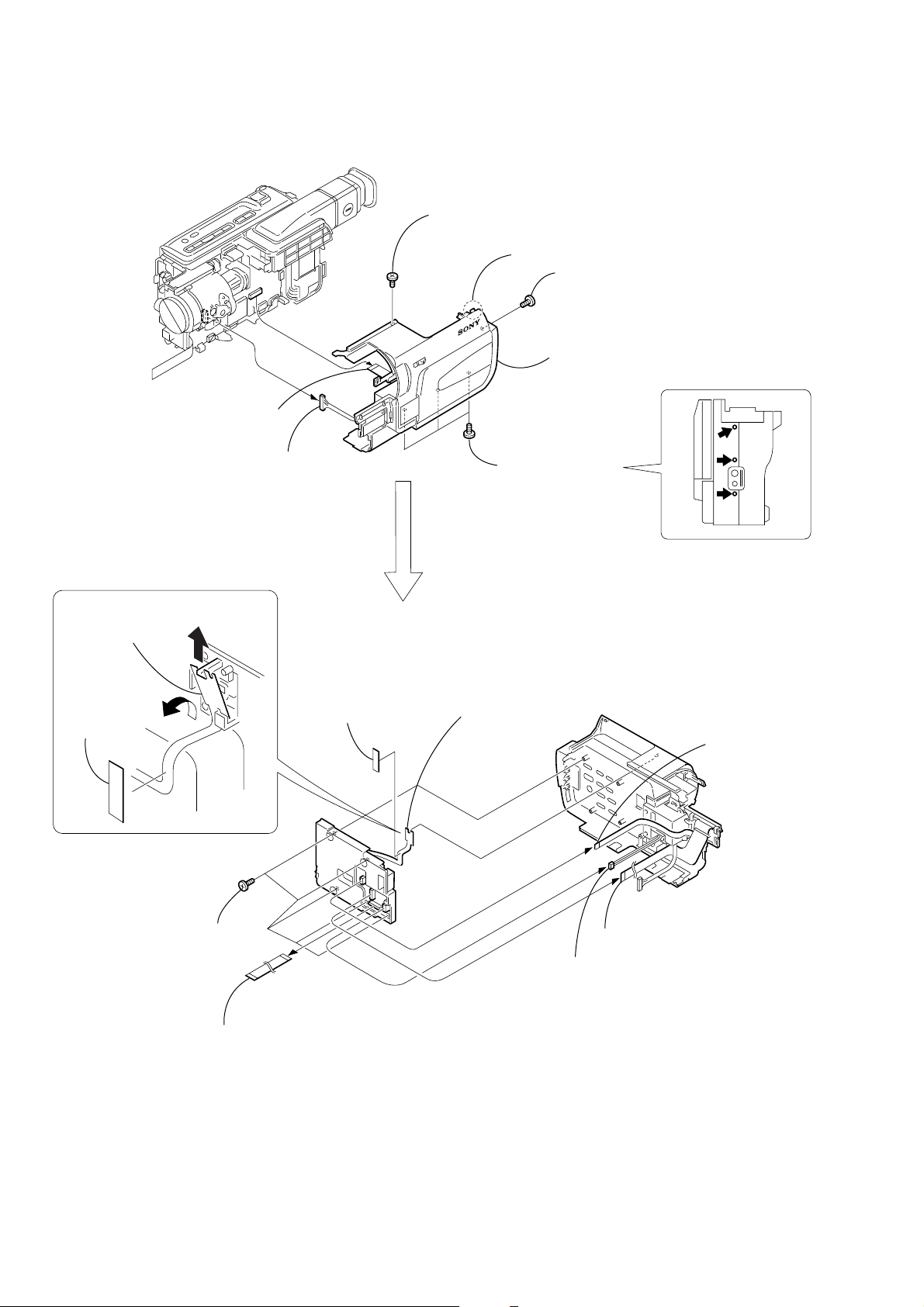
2-3. FRONT PANEL SECTION (MI-041 BOARD)
MI-041
Board
3
MI screw
(M2 × 4) (H)
1
Open the jack cover
2
Two MI screws
(M2 × 4) (H)
4
Two MI screws
(M2 × 4) (H)
5
Claw
2
Four claws
3
Microphone
retainer (rear)
4
Microphone
retainer (front)
7
Front panel section
6
FP-263 flexible
board (24P)
3
T wo tapping
screws (B2 × 5)
2
Microphone (Lch) (2P)
6
Microphone (Lch)
5
Microphone (Rch)
4
MI-041 board
1
T wo tapping
screws (B2 × 5)
1
Microphone (Rch) (2P)
2-4. CABINET (L) SECTION
6
Two MI screws
(M2
×
4) (H)
5
MI screw
(M2
1
×
4) (H)
— 11 —
4
MI screw
(M2
×
4) (H)
7
MI screw
(M2
×
4) (H)
3
2
Two MI screws
(M2
8
Cabinet (L) section
Cassette lid assembly
×
4) (H)
Page 12
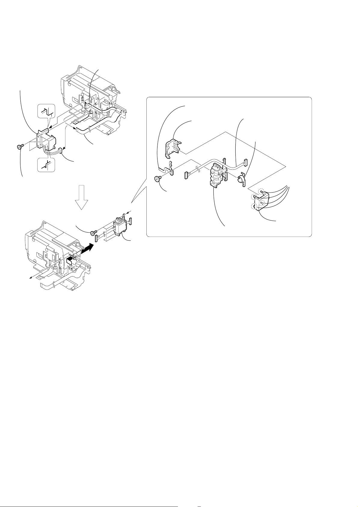
2-5. CABINET (R) SECTION, CONTROL SWITCH BLOCK (CF-1000)
1
MI screw
(M2
×
4) (H)
4
Claw
6
FFC-295 flexible
flat cable (24P)
5
Harness
(PD-110) (20P)
3
Three MI screws
(M2
2
MI screw
(M2
×
4) (H)
7
Cabinet (R) section
×
4) (H)
7
Remove the control switch block
(CF-1000) in the direction of the
arrow
Tape (A)
AB
.
B
A
5
Five tapping
screws (B2
1
×
5)
FFC-295 flexible flat cable (24P)
6
T ape (A)
8
Control switch block
(CF-1000)
2
FP-260 flexible board (16P)
4
Push switch (2P)
3
Electro luminous
element (4P)
— 12 —
Page 13
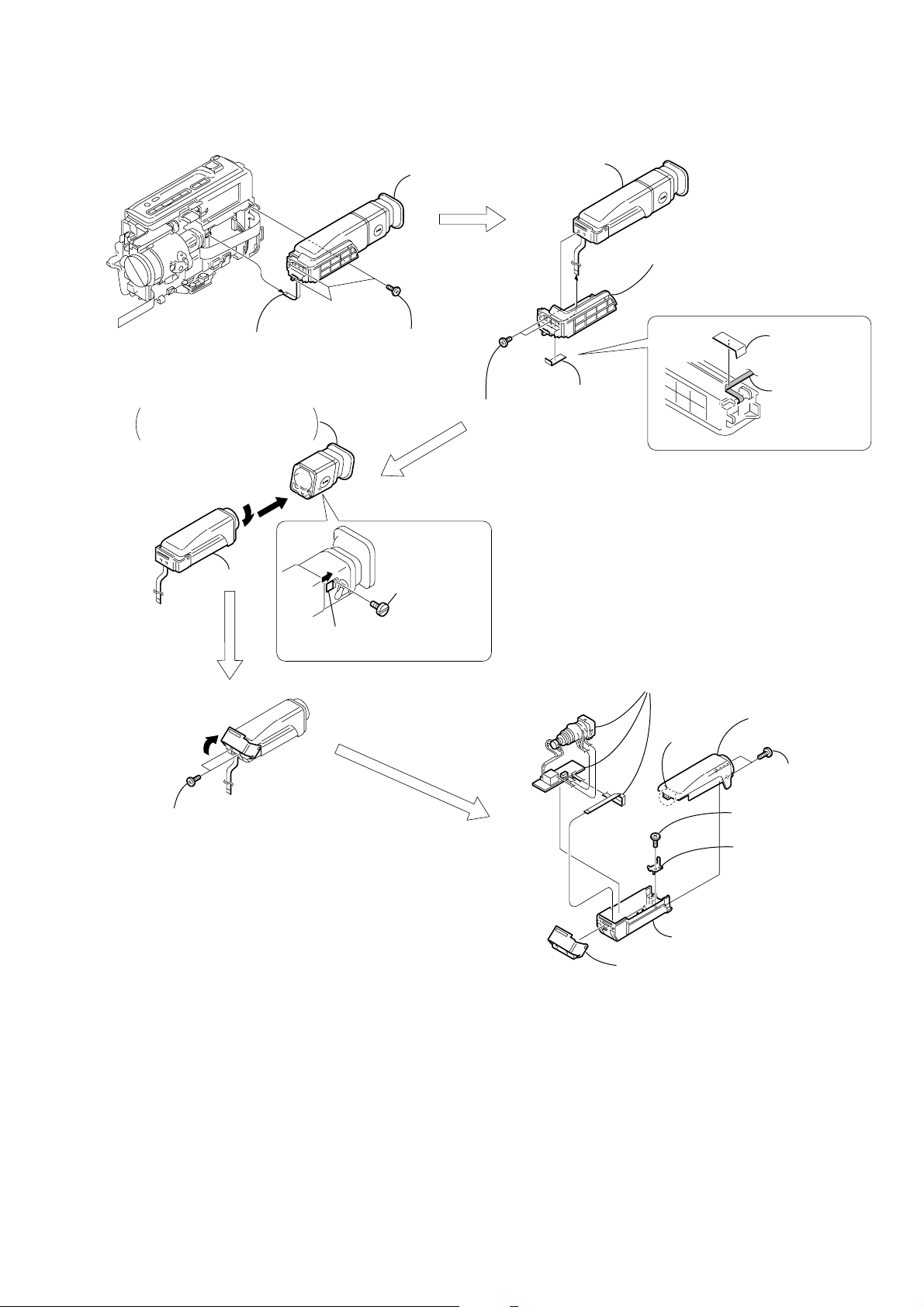
2-6. EVF SECTION (VF-129 BOARD)
1
FFC-289 flexible
flat cable (4P)
Finder (S) assembly
3
Rotate it in the direction of
the arrow B and remove it
in the direction of the arrow C.
C
B
4
2
Three tapping
screws (B2 × 5)
A
3
EVF section
1
F lock
screw (T)
2
Two loose
stopper screws
(M2 × 3)
4
1
T ape (A)
3
VF base B
PRECAUTION DURING
INSTALLATION
Tape (A)
FFC-289 flexible
flat cable
1
2
T wo tapping
screws (B2 × 5)
2
Slide the button in the
direction of the arrow A.
8
CRT assembly, VF-129 board,
FFC-289 flexible flat cable
3
Claw
5
(B2 × 5)
6
7
EVF cabinet lower B
1
VF hinge assembly
4
EVF cabinet
upper B assembly
2
T wo tapping
screws
(B2 × 5)
T apping screw
EVF tally
— 13 —
Page 14
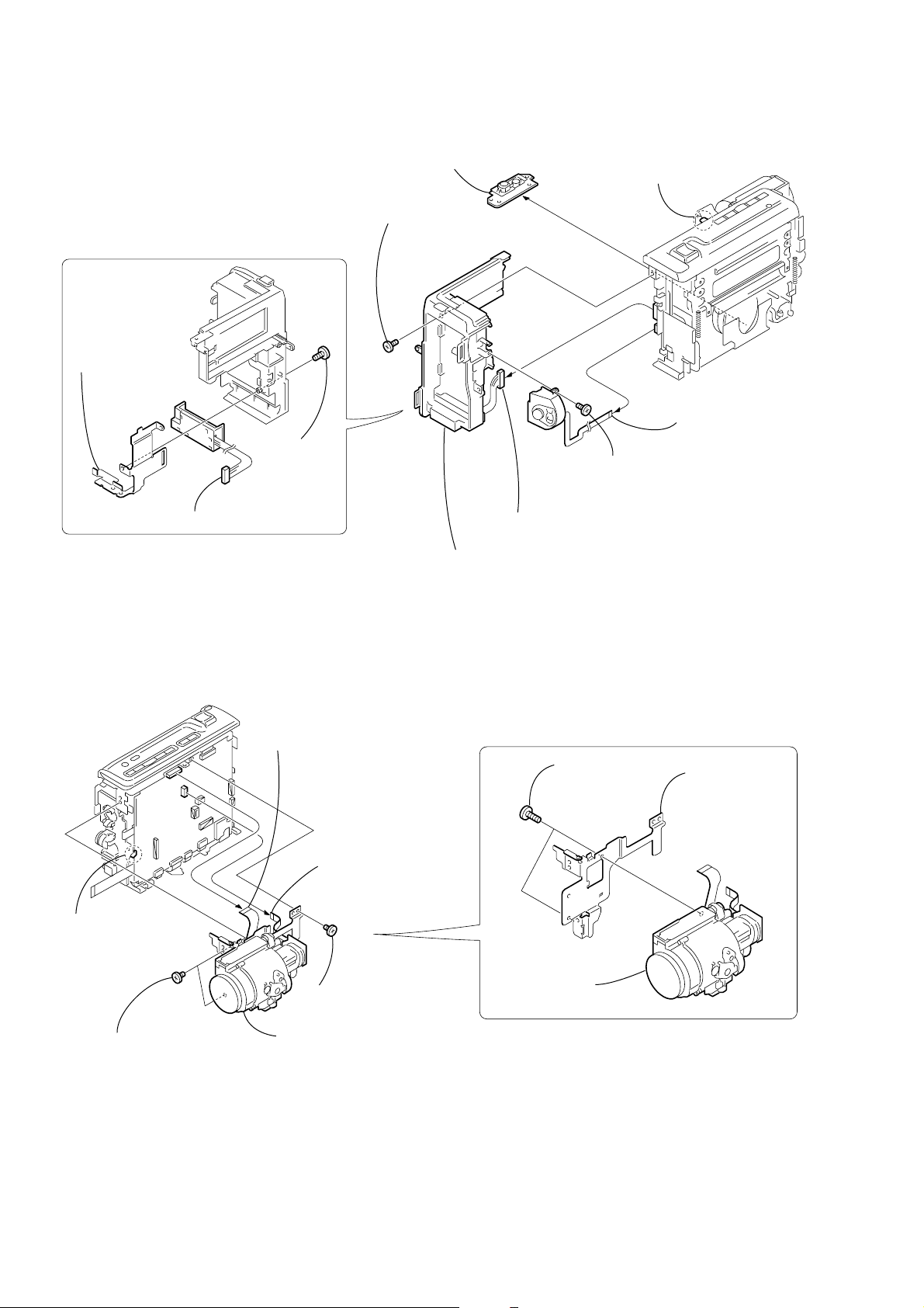
2-7. BATTERY PANEL SECTION (BATTERY TERMINAL BOARD)
1
T ripod screw
4
MI screw
(M2 × 4) (H)
2
Strap sheet
metal (lower)
1
MI screw
×
4) (H)
(M2
3
Battery terminal board
6
Battery panel section
3
MI screw
(M2 × 4) (H)
2
Battery terminal board (7P)
5
Claw
7
Control switch block
(SS-1000) (5P)
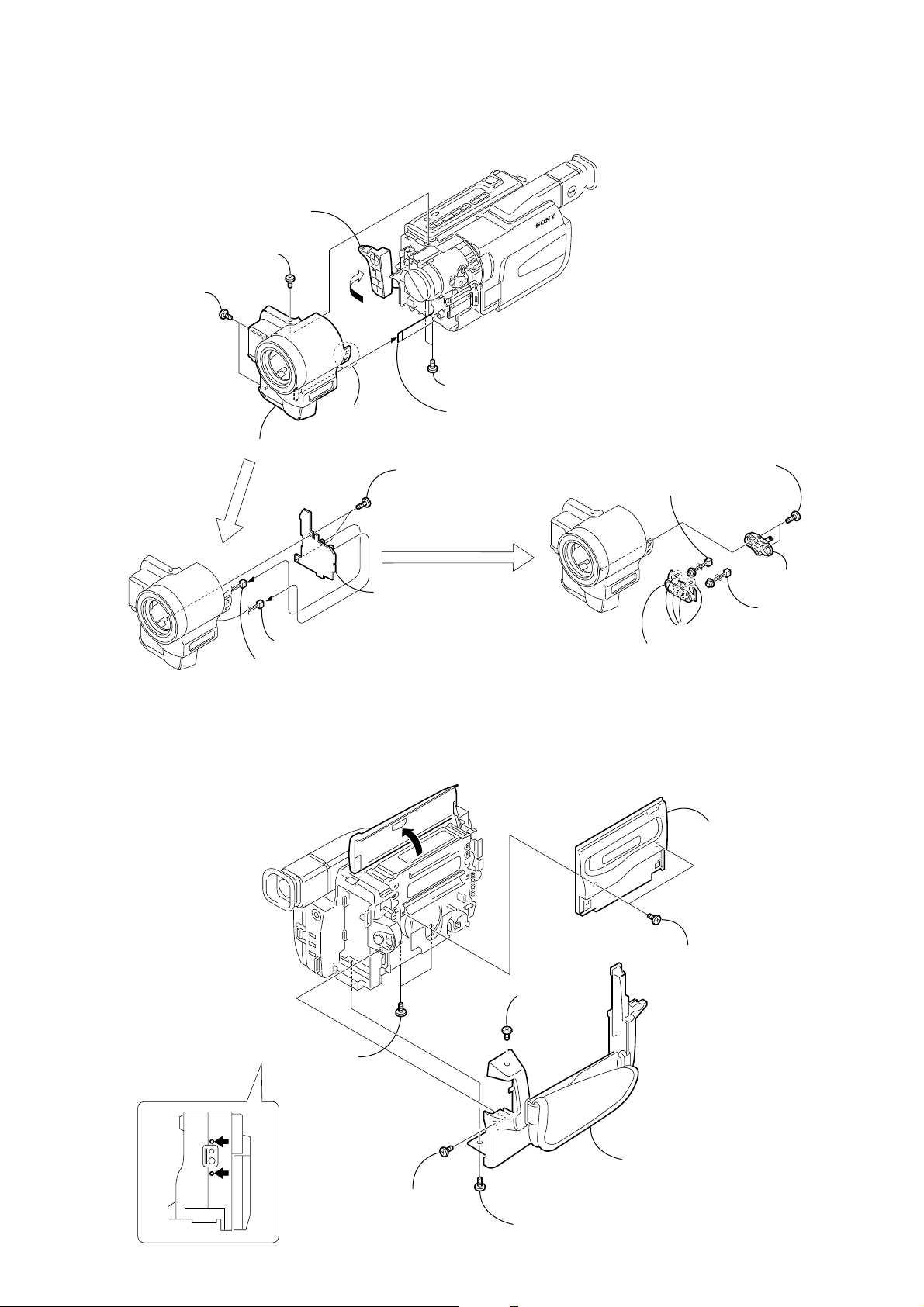
2-8. LENS SECTION
VC-256
Board
5
Claw
4
T wo screws
(M2
×
lock ace, p2
3),
2
Flexible board
(from lens block)(24P)
1
FP-259 flexible
board (14P)
3
Screw
(M2
×
lock ace, p2
6
3),
1
screws (B2
3
Lens section
T wo tapping
2
×
5)
Lens frame
— 14 —
Page 15
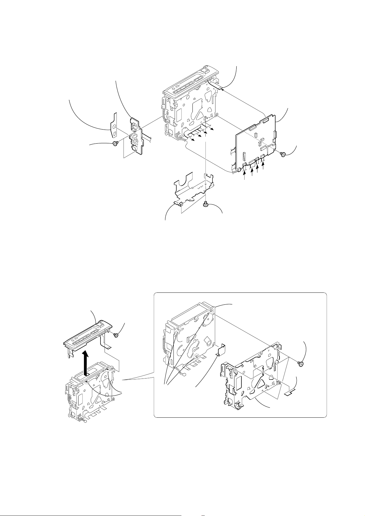
2-9. VC-256 BOARD
4
Jack cushion
3
T wo screws
(M2 × 3),
lock ace, p2
5
FP-258 flexible board
2
MD frame B
A
B
D
C
1
lock ace, p2
7
Control switch block
(FK-1000) (12P)
VC-256
Board
D
C
B
A
Two screws (M2 × 3),
8
VC-256 board
6
Screw (M2 × 3),
lock ace, p2
2-10. MECHANISM DECK
4
Control switch block
(FK-1000)
3
1
Screw
×
(M2
lock ace, p2
3),
2
Two claws
REMOVING THE MECHANISM DECK
6
Mechanism deck
3
Three
dowels
5
MD sheet
1
Three screws
(M1.7
4
MD frame A
×
2.5), p
2
absorbing
sheet
— 15 —
Page 16
2-11. HINGE SECTION
5
Hinge blind,
Push switch
2
4
Three tapping
screws (B2
×
5)
1
Four tapping
screws (B2
3
Electro luminous
element (4P)
1
FP-260 flexible
board (16P)
Push switch (2P)
×
5)
REMOVING THE HINGE ASSEMBLY
7
Control switch block
(PR-10000)
3
Hinge cover M
6
Screw
(M1.7
A
×
2.5), p
5
Harness (PD-110)
8
Hinge assembly
4
Harness clamp
2
cover C
1
claws
Hinge
Four
A
2
— 16 —
Page 17

3. REPAIR PARTS LIST
3-1. EXPLODED VIEWS
NOTE:
• -XX, -X mean standardized parts, so they may
have some differences from the original one.
• Items marked “*” are not stocked since they
are seldom required for routine service. Some
delay should be anticipated when ordering these
items.
3-1-1. OVERALL SECTION
• The mechanical parts with no reference number
in the exploded views are not supplied.
The components identified by mark 0 or
dotted line with mark 0 are critical for safety.
Replace only with part number specified.
11
A
10
9
8
LAMP, HALOGEN
XB-3D (HL6V/3W)
7
not
supplied
6
A
12
not supplied
6
5
B
14
not
supplied
1
6
13
1
19
6
Cabinet (L) section
(See page 18)
15
C
MIC901
3
MI-041
4
16
MIC902
B
Cabinet (R) section
6
(See page 21)
6
C
1
6
1
17
2
18
Ref. No. Part No. Description Remarks Ref. No. Part No. Description Remarks
1 3-948-339-61 TAPPING
2 3-065-468-01 RETAINER (REAR), MICROPHONE
3 3-065-467-01 RETAINER (FRONT), MICROPHONE
* 4 3-065-470-01 CUSHION (10), MICROPHONE
5 X-3951-220-1 PANEL (10) ASSY, F
6 3-067-347-01 MI SCREW M2 (H)
7 1-518-723-21 LIGHT, VIDEO
8 X-3949-376-1 CAP (N) ASSY, LENS
9 3-065-433-01 COVER (10), JACK
10 X-3951-194-1 CABINET L (10) ASSY
11 3-052-815-01 BELT (ES), GRIP
* 12 3-065-455-01 STOPPER (FRONT) (10), BELT
* 13 3-065-457-01 PLATE REAR (10), L GROUND
14 3-058-622-01 STOPPER (REAR), BELT
15 not supplied MI-041 (S) BOARD, COMPLETE
16 3-987-717-01 SCREW, TRIPOD
17 1-475-141-61 REMOTE COMMANDER (RMT-814)
18 3-742-854-01 LID, BATTERY CASE (FOR RMT-814)
19 3-065-464-01 WINDOW (12), LCD
MIC901 1-542-452-11 MICROPHONE (Rch)
MIC902 1-542-452-11 MICROPHONE (Lch)
— 17 —
Page 18

3-1-2. CABINET (L) SECTION
58
57
Mechanism deck
66
53
F
55
H
E
53
D
53
68
B
A
C
71
61
not
supplied
54
67
Lens section
(See page 20)
59
51
70
65
53
53
E
52
H
58
I
BT901
56
VC-256
Board
D
C
B
A
63
62
J
K
F
53
I
J
not supplied
60
EVF section
(See page 19)
G
69
58
G
58
64
66
Ref. No. Part No. Description Remarks Ref. No. Part No. Description Remarks
51 1-680-203-11 FP-263 FLEXIBLE BOARD
* 52 3-065-428-01 FRAME B (10), MD
53 3-968-729-51 SCREW (M2), LOCK ACE, P2
54 1-680-199-11 FP-258 FLEXIBLE BOARD
* 55 3-065-429-01 FRAME (10), LENS
56 4-974-725-01 SCREW (M1.7X2.5), P
57 X-3951-227-1 LID (12) ASSY, CASSETTE
58 3-067-347-01 MI SCREW M2 (H)
59 1-476-423-11 SWITCH BLOCK, CONTROL (FK-1000)
60 3-065-421-01 SHEET METAL (LOWER)(12), STRAP
61 3-066-169-01 SHEET, MD
62 1-476-424-41 SWITCH BLOCK, CONTROL (SS-1000)
63 X-3951-196-1 PANEL (12) ASSY, BATTERY
64 3-987-656-01 LID, JACK
65 not supplied VC-256 (IB-S) BOARD, COMPLETE (SERVICE)
66 3-948-339-61 TAPPING
67 1-680-200-11 FP-259 FLEXIBLE BOARD
68 3-065-662-01 LABEL, LS CAUTION
69 3-941-343-21 TAPE (A)
70 3-067-254-01 SHEET (10), ABSORBING
71 3-066-949-01 CUSHION (12), JACK
BT901 1-694-384-11 TERMINAL BOARD, BATTERY
— 18 —
Page 19

3-1-3. EVF SECTION
112
102
108
not
supplied
114
104
113
107
V901
105
111
103
109
110
103
106
103
101
Ref. No. Part No. Description Remarks Ref. No. Part No. Description Remarks
101 3-061-794-01 SCREW, LOOSE STOPPER
102 3-065-481-01 BASE B (12), VF
103 3-948-339-81 TAPPING
104 X-3950-230-1 HINGE ASSY, VF
105 3-065-480-01 CABINET LOWER B (12), EVF
106 3-053-681-01 TALLY, EVF
107 1-792-454-11 CABLE, FLEXIBLE FLAT (FFC-289)
108 not supplied VF-129 (P) BOARD, COMPLETE
109 X-3951-202-1 CABINET UPPER B (12) ASSY, EVF
110 3-975-898-01 SCREW (T), F LOCK
111 X-3949-329-1 FINDER (S) ASSY
112 3-941-343-21 TAPE (A)
113 3-709-272-01 COVER, HIGH VOLTAGE (SERVICE)
114 3-709-273-01 MASK, CRT (SERVICE)
0 V901 not supplied CRT ASSY (M01KXX90WB)
— 19 —
Note : The components identified by mark 0 or dotted
line with mark 0 are critical for safety.
Replace only with part number specified.
Page 20

3-1-4. LENS SECTION
163
161
160
162
IC191
155
154
152
159
M905
153
M906
not
supplied
158
157
155
156
154
152
153
151
Ref. No. Part No. Description Remarks Ref. No. Part No. Description Remarks
151 not supplied DEVICE, LENS LSV-630A
152 not supplied IRIS FLEXIBLE ASSY 630
153 3-713-791-41 SCREW, TAPPING (M1.7X5), P2
154 3-713-791-51 SCREW, TAPPING (M1.7X3.5), P2
155 3-056-022-01 TAPPING (B1.7X3.5), HEAD
156 3-053-827-01 LEVER, IR
157 3-053-800-01 SPRING, RETAIN
158 3-053-799-01 GEA, IR
159 not supplied ADAPTOR (FK), CCD FITTING
160 not supplied FILTER BLOCK, OPTICAL
161 not supplied RUBBER (F), SEAL
162 not supplied CD-281 (X) BOARD,COMPLETE
163 3-318-203-11 SCREW (B1.7X6), TAPPING
IC191 not supplied CCD BLOCK ASSY (CCD IMAGER)
M905 not supplied MOTOR, STEPPING F630 (FOCUS)
M906 not supplied MOTOR, STEPPING Z600 (ZOOM)
— 20 —
Page 21

3-1-5. CABINET (R) SECTION
A
A
B
C
B
C
LCD section
(See page 22)
S901
LCD902
D901
201
201
201
202
201
201
207
208
203
209
204
205
206
: BT001 (Lithium battary) CF-1000 on the mount position.
The printed wiring board of the Control switch block (CF-1000) on which lithium battery is mounted, is not shown.]
Ref. No. Part No. Description Remarks Ref. No. Part No. Description Remarks
201 3-948-339-61 TAPPING
202 3-065-436-01 BLIND (12), HINGE
203 1-476-425-21 SWITCH BLOCK, CONTROL (CF-1000)
204 X-3951-223-1 CABINET R (12) ASSY
205 3-059-539-11 LID (103P), CPC
206 3-065-451-01 HOLDER (12), LCD
207 1-680-201-11 FP-260 FLEXIBLE BOARD
208 1-757-397-21 CABLE, FLEXIBLE FLAT (FFC-295)
209 3-941-343-21 TAPE (A)
0 D901 not supplied ELEMENT, ELECTRO LUMINOUS
LCD902 not supplied DISPLAY PANEL, LIQUID CRYSTAL
S901 1-771-848-11 SWITCH, PUSH
— 21 —
Note : The components identified by mark 0 or dotted
line with mark 0 are critical for safety.
Replace only with part number specified.
Page 22

3-1-6. LCD SECTION
265
255
256
254
257
266
253
259
258
260
252
C
A
251
261
262
PD-131
Board
263
B
ND901
C
264
LCD901
B
A
Ref. No. Part No. Description Remarks Ref. No. Part No. Description Remarks
251 3-067-347-01 MI SCREW M2 (H)
252 3-065-474-01 CABINET C (12), P
* 253 3-058-672-01 CLAMP, HARNESS
254 3-948-339-31 SCREW, TAPPING
255 3-065-477-01 COVER C (12), HINGE
256 X-3951-206-1 HINGE (12) ASSY
257 1-960-975-11 HARNESS (PD-110)
258 3-065-478-01 COVER M (12), HINGE
259 4-974-725-01 SCREW (M1.7X2.5), P
— 22 —
260 1-418-802-11 SWITCH BLOCK, CONTROL (PR-10000)
261 not supplied PD-131 (XC-2.5) BOARD, COMPLETE
262 3-968-729-51 SCREW (M2), LOCK ACE, P2
263 3-065-475-01 FRAME (12), PANEL
264 X-3951-199-1 CABINET M (12) ASSY, P
265 3-948-339-81 TAPPING
266 not supplied PLATE (12), PANEL ORNAMENT
LCD901 not supplied INDICATOR MODULE LIQUID CRYST (SERVICE)
0 ND901 not supplied TUBE, FLUORESCENT, COLD CATHODE
Note : The components identified by mark 0 or dotted
line with mark 0 are critical for safety.
Replace only with part number specified.
Page 23

2. GENERAL
DCR-TRV130E
This section is extracted
from instruction manual.
— 23 —
Page 24

— 24 —
Page 25

— 25 —
Page 26

— 26 —
Page 27

— 27 —
Page 28
— 28 —
Page 29

— 29 —
Page 30

— 30 —
Page 31

— 31 —
Page 32

— 32 —
Page 33
— 33 —
Page 34

— 34 —
Page 35

— 35 —
Page 36

— 36 —
Page 37

— 37 —
Page 38

— 38 —
Page 39
— 39 —
Page 40

— 40 —
Page 41
— 41 —
Page 42
— 42 —
Page 43

— 43 —
Page 44

— 44 —
Page 45

— 45 —
Page 46

— 46 —
Page 47

— 47 —
Page 48

— 48 —
Page 49

— 49 —
Page 50

— 50 —
Page 51

— 51 —
Page 52

DCR-TRV130E
9-929-860-41
Sony Corporation
Personal VIDEO Products Company
— 52 —
2001A1600-1
©2001.1
Published by Safety & Service Engineering Dept.
Page 53

Reverse
992986041.pdf
Revision History
Ver.
1.0
Date
2000.01
History
Official Release
Contents
—
S.M. Rev.
issued
—
 Loading...