

Snorkel TL37 User Manual [en, de, es, fr, it]
TL37
Operator Manual
This rst section of the Operator manual is the English language version.
Betriebsanleitung
Im zweiten Abschnitt dieser Betriebsanleitung nden Sie die Deutsche Version.
Manuel Utilisateur
èLa troisième section de ce manuel est la version en langue Française.
Manual del Usuario
El apartado cuarto de este manual del usuario corresponde a la versión en Españo.
Manuale d’Uso
La quinta sezione di questo manuale d'uso è la versione in lingua Italiana.
(EN) Manual part number 508150-000 for serial nu mbers 7000 to current.
(DE) Bestellnummer 50 8150-000 ab Seriennummer 7000 fortlaufend.
(FR) Manuel Pièce numéro 508150-000 pour numéro série 7000 jusqu'au
numéro courant.
(ES) El número de referencia para el manual es el 508150-000 para la
números de serie del 7000 hasta el actual.
(IT) Manuale Ricambi Numero 508150-000 per Numeri di Serie da 7000
all’attuale.
Jan 08

Operation M
ANUAL
TL37
This manual covers Serial Numbers 7000 to Current
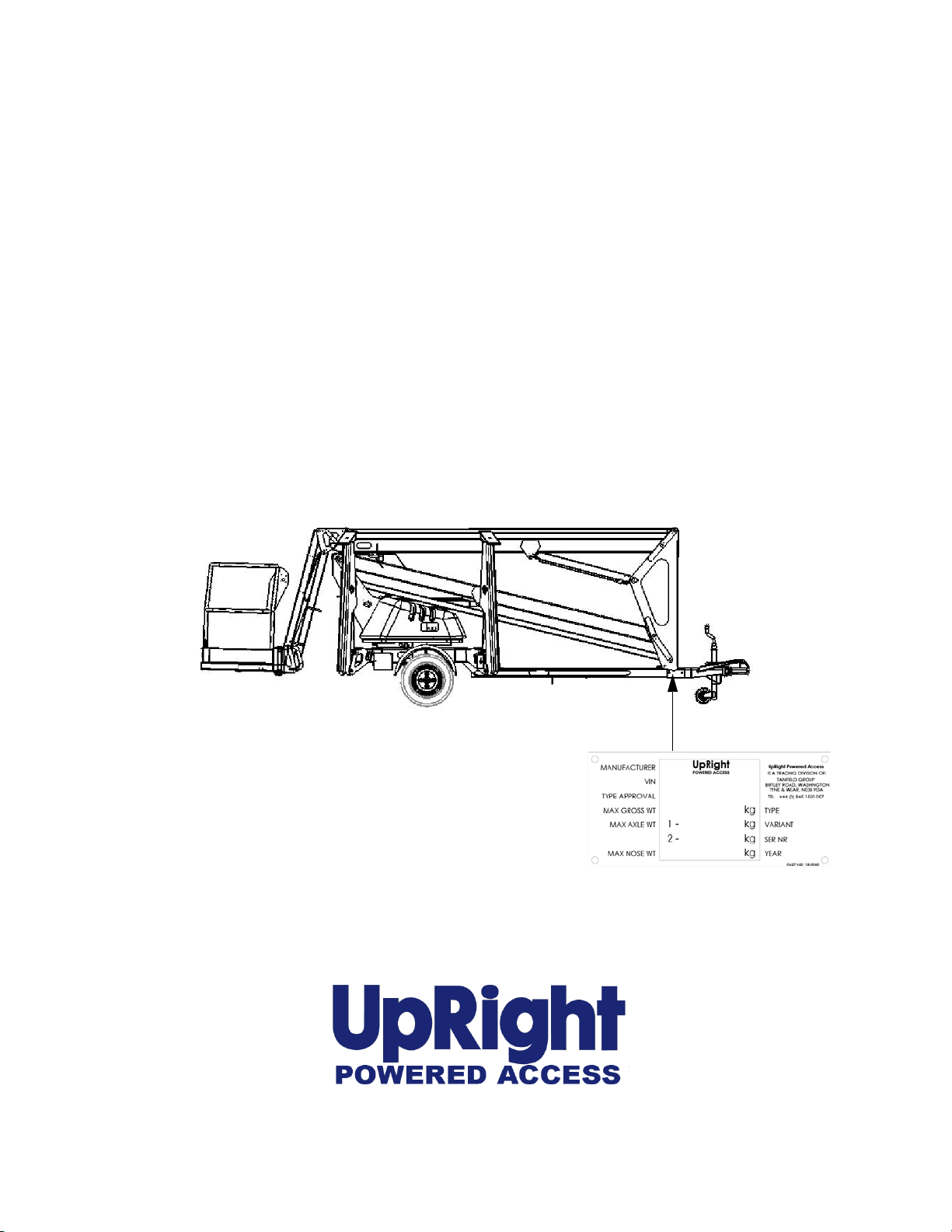
When contacting UpRight Powered Access for service orparts information, always
include the MODEL and SERIAL NUMBER from the machine namplate.
The serial number is stmped into the
chassis above the machine nameplate.
e.g. 7 # # #
www.upright.com


CONTENTS
Page
Introduction 4
Description of Equipment 5
Technical Specification 6
Working Envelope 7
Operator Requirements 8
Warning Notices 9
. Beaufort Scale 10
Towing Instructions 11
PRE-START CHECKS
Pre-Start Checks 13
Batteries, & Power Pack 15
Setting Up 16
Extending Structure 18
. Basket Controls 18
. Ground Controls 19
Safety Harness 20
Emergency Controls
. Emergency Stops 20
. Emergency Lower (Aided) 21
. Emergency Lower (Unaided) 22
. Emergency Slew 22
. Cage Overload 23
. Emergency Battery Isolation 24
Stowing the Machine 25
2

CONTENTS
Page
Maintenance
. Daily Checks 26
. Weekly and Monthly Checks 27
. Slew Drive and Limit Switches 28
Trailer lights 29
Appendices
App’1 Petrol/Bi-fuel Option. 30
App’2 Generator Option. 31
App’3 Mains connection. 32
3
INTRODUCTION
The UpRight TL37’s unique combination of strength, versatility and simplicity,
have made it an instant leader in its class.
Its exceptional working envelope, despite the low towing weight, is achieved
thanks to our innovative boom design.
The third flick boom, with 130 DEGREES working arc, guarantees access to the
most hard to reach places, while the 90 DEGREES basket rotation provides the
precision positioning that is vital for working in tight spaces.
UpRight has a global reputation for innovation and a proud heritage in the
design and manufacture of high quality powered equipment.
The company was founded in the UK more than 25 years ago, on the principle of
constantly improving service excellence for end users.
Every model in our growing range of versatile, trailer mounted units is a class
leader and together they have set new industry benchmarks.
Our commitment to research and design, plus 250,000sq ft of same site
fabrication, build and support capacity, mean UpRight can offer complete solutions to meet even the most demanding access applications.
UpRight has third party accreditation to quality standard ISO 9001 and the full
range proudly carries the CE mark, complying with or exceeding all relevant standards and EC directives.
UpRight Powered Access is a member of the IPAF
International Powered Access Federation.
To ensure you are fully aware of safety and operational
information, the following symbols are used throughout this
manual;
This type of box contains, Points of operation to NOTE.
The information contained in this type of box contains, WARNING
!
1
text. It gives Warnings about the risk of Damage to equipment,
and possibly personnel.
The information contained in this type of box contains, DANGER
text. It gives Warnings about the risk of PERSONAL INJURY to the
operator and or others.
4

DESCRIPTION OF EQUIPMENT
The UpRight TL37 is of the parallel linkage vertical boom design, mounted on
either a road towable trailer, or on industrial bogie chassis . The unique yet very
simple boom configuration gives the maximum safety and control ability combined
with a robust construction to withstand a heavy working environment.
The TL37 machine is designed for two man capacity with 215 kg S.W.L.
The machine incorporates a bottom boom with tie rod, a short vertical boom and a
top boom with tie rod. The TL37 has also an independent hydraulically operated
Flick-Out Boom and Rotating Cage for extra manoeuvrability.
The hydraulic system is of a fail-safe design throughout, with built-in hydraulic lock
valves on all the rams as a precaution against hose failure. The machine is
controlled by means of proportional manual lever operated valves. These valves are
located at both the base and in the cage, as standard.
Emergency lower valves are fitted as standard to allow the machine to be lowered
from the Base. Additionally, a hand pump is fitted in the cage for emergency
operation.
The hydraulically operated outriggers are fitted with load sensing interlocks, to
prevent the booms being raised without the outriggers being extended and under
load. An interlock prevents the hydraulic outriggers being accidentally retracted
while the booms are raised. A simple system of warning lights show the power is
on and each of the outriggers is under load.
Performance.
Maximum Working Height 13.1 m
Maximum Working Outreach 5.9 m
Capacity (2-man working) 215 kg
Slewing Arc 700°
Airborne Noise Emissions (Battery) 70 dB(A)
(Engine) 100 dB(A)
(Diesel) 103 dB(A)
Construction Standards.
The machine complies fully with the requirements of the following EEC Directives:
Directive 98/37/EC, the ‘Machinery Directive’.
Directive 89/336/EEC, as amended – the ‘Electromagnetic Compatibility Directive’.
Directive 73/23/EEC, as amended – the ‘Low Voltage Directive’.
The machine is designed and tested in accordance with all relevant B.S.I. and
European Standards including EN280.
5

TECHNICAL SPECIFICATION
Cage Dimensions
Length 1.20m
Width 0.80m
Guard-rail Height 1.10m
Toe-board Height 0.15m
Operating Dimensions
Maximum Working Height 13.10m
Maximum Cage Height 11.10m
Maximum Outreach ( From centre of rotation ) 5.90m
Travel Dimensions
Towing Length 6.43m
Closed Width 1.48m
Closed Height 1.95m
Weight (Battery Model) 1450kg (unladen)
Operating Parameters
Safe Working Load 215 kg
Maximum Horizontal Pull 400 N
Maximum Wind Speed 12.5 ms
Rotation 700°
Cage Slew 90°
Equipment
Bottom Ram Double acting: Bore Ø 60.0 mm
Rod Ø 40.0 mm
Top Ram Double acting: Bore Ø 60.0 mm
Rod Ø 40.0 mm
Flick Ram Double acting: Bore Ø 60.0 mm
Rod Ø 40.0 mm
Stabiliser Ram Double acting: Bore Ø 70.0 mm
Rod Ø 40.0 mm
Bottom & Top Ram Lock Valves Pilot operated over centre valves
Control Valve (Cage) Monoblock unit consisting of five
double acting spools
Control Valve (Ground) Monoblock unit consisting of four
double acting spools
Control Valve (Stabiliser) Monoblock unit consisting of four
double acting spools
Bushes Acetol resin polymer with sintered
bronze base (DX)
Pivot Pins Stainless Steel Bright Bar
To Grade BS970 303 S31 CW
-1
6

WORKING ENVELOPE
7

OPERATOR REQUIREMENTS
1. To operate the machine you must be medically fit and have no problems
with eyesight or hearing.
2. You must have a good head for heights.
3. Your primary concern must be the safe operation of the work platform, the
safety of the people working with you, and the safety of other persons in
your working area.
4. You must be familiar with the contents of this manual, and at no time
attempt to operate the machine beyond the recommended limits.
5. The proper care of the work platform is a major factor in ensuring the safety
of those who work with it.
6. You must not misuse the machine or ignore or interfere with the devices
that have been provided to maintain safety.
7. Operation of the machine should be restricted to personnel who have been
authorised to operate the equipment and have received proper training.
8
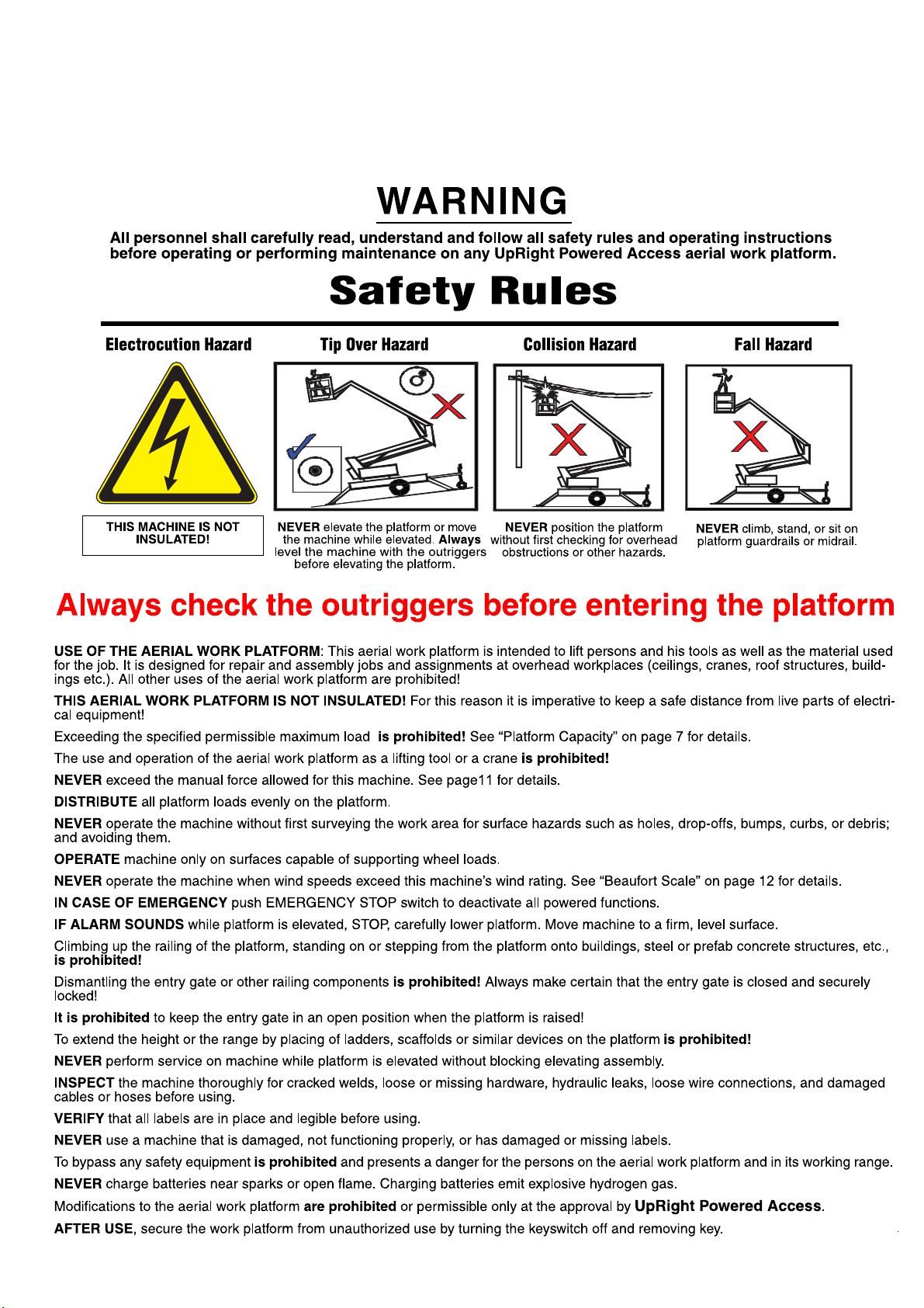
WARNING NOTICES
1. DO NOT operate this machine unless you have been fully trained in its safe
use.
2. DO NOT operate the machine on soft, slippery or sloping ground unless
adequate precautions have been taken.
The stabilisers are designed to operate on firm level ground with a minimum
bearing strength of 50N/cm
The maximum load imposed by an outrigger is 10.3kN.
Advice should be obtained from UpRight as to the type of supports and
precautions required before attempting to operate the machine outside
these parameters.
3. DO NOT use any equipment in the basket to increase the reach or working
height of the machine, e.g. ladders.
4. DO NOT fit any additional equipment to the machine that would increase
the wind loading, e.g. notice boards.
5. DO NOT use the machine for any application that may produce special loads
or forces: the manufacturer, UpRight, must be consulted for approval of
special applications prior to use.
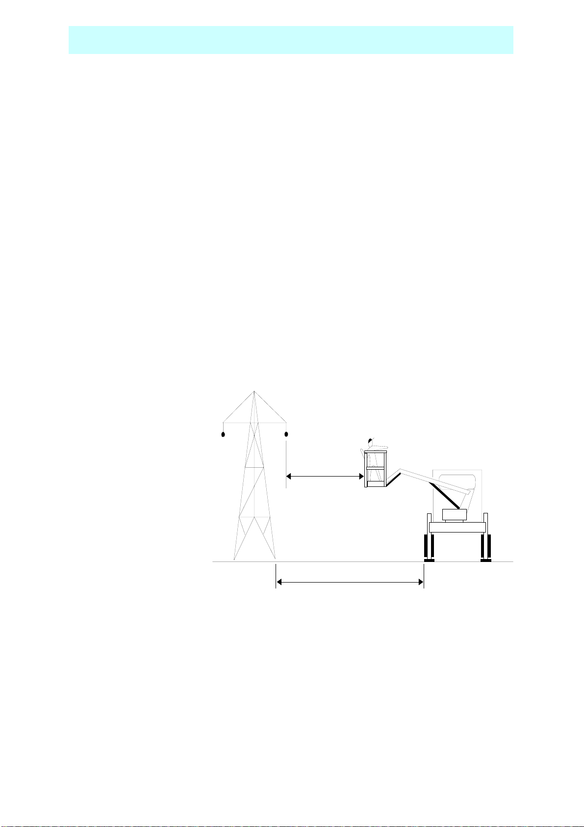
6. DO NOT use the
machine close to
live electrical
conductors. The
minimum safe
working distance
for a machine
working near
overhead power
cables is the
maximum
extended length of
the booms plus 15
metres, measured
with the booms
pointing towards
the lines, i.e. safe
working distance for the TL37 is 20 metres. It is the operator‘s responsibility
to ensure that, when working in the vicinity of live overhead high-voltage
lines, the minimum safe working distance is maintained. Erect a simple
barrier tape at the safe distance.
7. WORKING CLOSE TO POWER CABLES – if work has to be carried out at less
than the safe working distance, the operator must ensure that the
electricity supply has been switched off. Before commencing work, a
written permit to work must be obtained from the owners of the power
cables or the responsible authority.
2
.
15m
15m
20m
26m
9
WARNING NOTICES
8. DO NOT operate the machine unless all four outriggers are down and in full
contact with the ground. The machine must be level and the wheels lifted
visibly clear of the surface before the booms are raised.
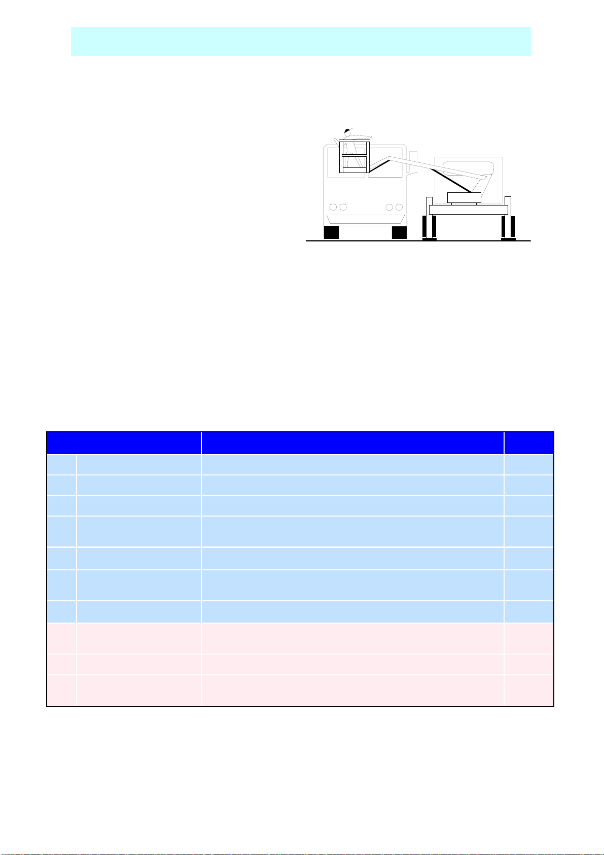
9. DO NOT move the machine with the
basket raised and never allow cage
or booms to slew into the path of
oncoming vehicles.
10. DO NOT operate the machine if the wind speed exceeds 12.5 m/s. Be aware
that, when working near high buildings or structures, shielding and
funnelling effects may cause high wind forces on days when the nominal
wind speed in the open is low. Wind speed can either be measured from
the work platform with a hand held anemometer or estimated using the
Beaufort Scale.
BEAUFORT WIND SPEED SCALE
The Beaufort Scale of wind force is accepted internationally and is used in communicating
weather conditions. It consists of numbers 0 - 12, each representing a certain strength of
velocity of wind at 10m (33ft.) above ground in t he open.
Numbers 10-12are not shown in this table.
DESCRIPTION OF WIND
0 CALM
1 LIGHT AIR
2 LIGHT BREEZE
3 GENTLE BREEZE
4 MODERATE BREEZE
5 FRESH BREEZE
6 STRONG BREEZE
7 NEAR GALE
SPECIFICATION FOR USE ON LAND M/Sec
Calm – smoke rises vertically
Direction of wind shown by smoke drift but not by wind vanes.
Wind felt on faces; leaves rustle; ordinary vanes moved by wind.
Leaves and small twigs in constant motion; wind extends light
flag.
Raises dust and loose paper; small branches are moved.
Small trees in leaf begin to sway; crested wavelets form on inland
waterways.
Large branches in motion; umbrellas used with difficulty.
Whole trees in motion; inconvenience felt when walking against
wind.
0-0.5
0.6-1.5
1.6-3.0
3.5-5
6-8
9-10
11-13
14-17
8 GALE
9 STRONG GALE
Approximate corrections for wind speeds at other heights are:
2m subtract 30%; 3m subtract 20%; 6m subtract 10%
10
Breaks twigs off trees; generally impedes progress.
Slight structural damage occurs (chimney pots and slates re-
moved)
15m add 10%; 30m add 25%
18-21
22-24
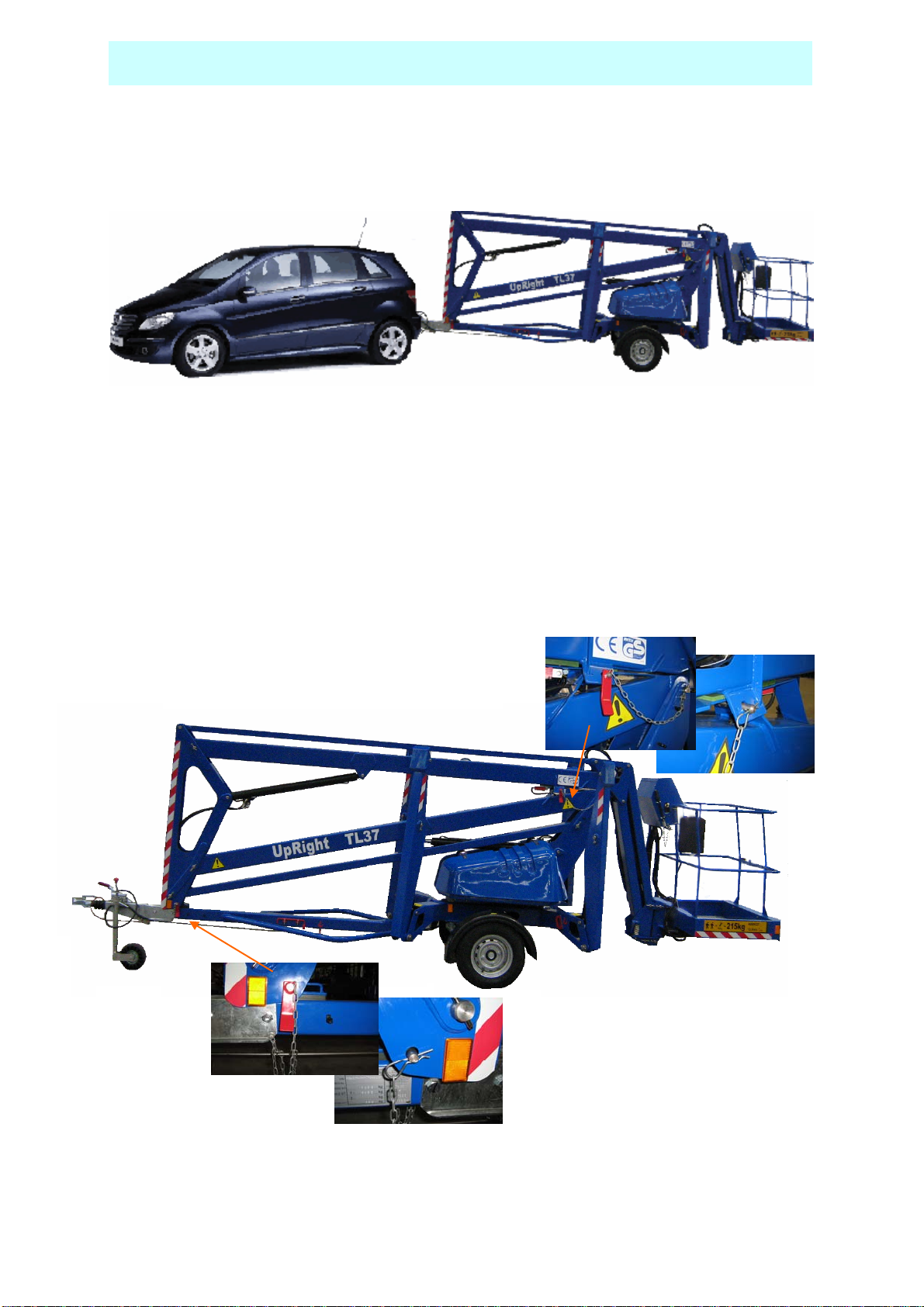
TOWING INSTRUCTIONS
Trailer mounted machines are fitted with suspension units that may be safely
towed behind a car or van at speeds of up 50mph (80km/h) where permitted.
1. Before towing, check the capacity of the vehicle being used.
(Machine weight will increase if optional extras are fitted)
2. Ensure that the road tyres and brakes are in good, serviceable condition.
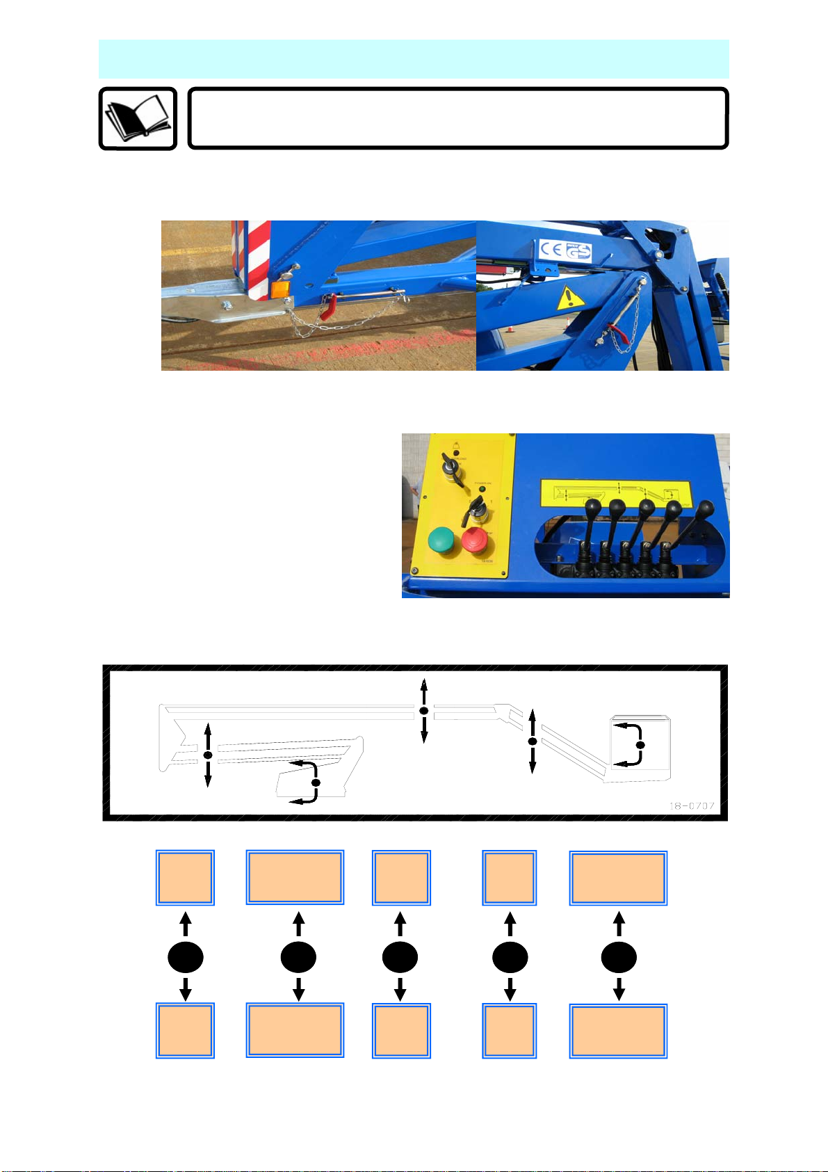
3. Ensure that all booms are fully lowered and both the transit pins are fitted
through the transit pin holes and secured with the “R” clip on the end of the
chain. (see photographs below)
11
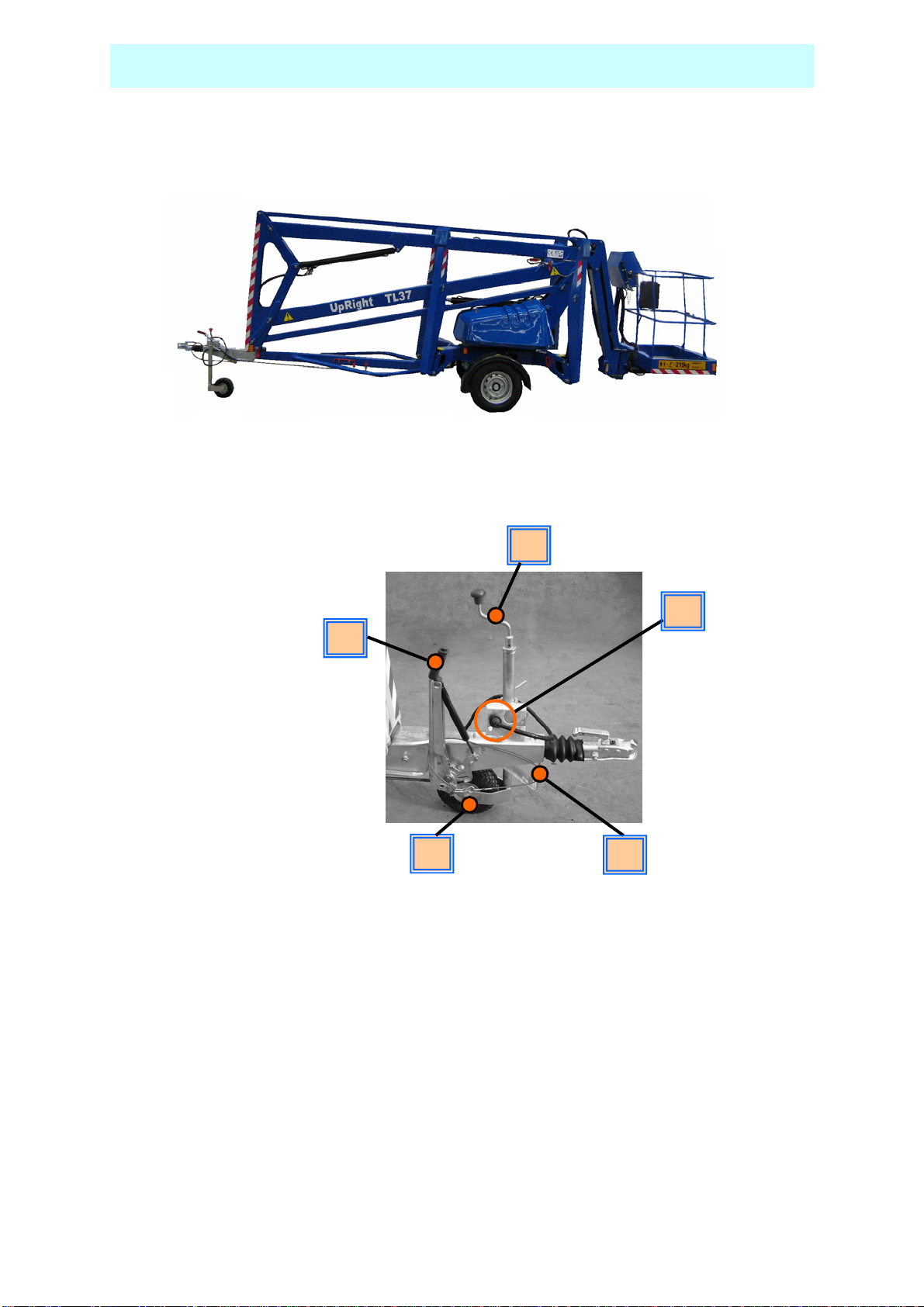
TOWING INSTRUCTIONS
4. Ensure that all outriggers are fully raised.
5. Use the Jockey Wheel to raise or lower the tow bar coupling to position the
machine above the 50mm ball hitch on the towing vehicle.
6. Apply the handbrake.
7. Lower the tow bar coupling down onto the ball hitch using the Jockey Wheel
8. Secure the breakaway cable,
(Ensure correct engagement of 50mm ball).
9. Fully raise the Jockey Wheel and lock in position.
10. Release the Handbrake.
11. Plug in the trailer lights (7 pin plug) and check that both vehicle and trailer
lights are working correctly.
6
9
7
11
8
12
PRE-START CHECKS
The following Pre-Start Checks should be carried out before taking the
machine to the place of work.
1. Damaged or Loose Fittings.
Visually Inspect the machine for signs of wear and tear, damage, loose or
missing parts.
2. Wheels. (For towing only)
Check tyres are at the correct pressure, 55 psi (3.8 bar) and that the
wheel nuts are tightened using the correct torque setting (100Nm).
3. Hydraulic fluid.
The hydraulic oil tank is located underneath the slew cover on the left
hand side of the machine (looking from the cage end).
With the booms and outriggers in the transport position, the hydraulic oil
level should be visible between the upper and lower marks of the dipstick.
Do Not Overfill the Hydraulic Tank
Serious injury or even death may result by not carrying out the
following checks of the interlock system before the platform is
1
Top up with ISO Grade 22 hydraulic oil if necessary.
4. Safety Switches.
Visually check the cage overload switch is free from damage.
Check all limit switch arms are free from damage and move easily .
With outriggers in transport position, it must not be possible to operate the
extending structure.
With outriggers deployed, under load and top or bottom boom raised
used!
The flick boom is not interlocked with the outriggers.
approximately 50mm, it must NOT be possible to operate the outrigger
controls.
5. Emergency Stop Switches.
Emergency stop switches must operate correctly. Check that each stops the
machine’s controls and that restarting is prevented until all stop switches
are unlatched.
13

PRE-START CHECKS
6. Emergency Lower/Slew.
With the top and bottom booms raised approximately 500mm each and the
unit switched off, check:
The emergency slew can be operated with the slew handle provided.
The emergency lower valves located on the lift cylinders lower the boom
when pushed in a slow and controlled manner and that the boom movement
is stopped on releasing the valve
To Reset the hydraulic system after checks;
Fully slew the Basket to the right, so that he ram is fully extended.
Fully extend the Outriggers while still maintaining Level. (check the bubble)
Using the ground controls, fully extend both Top and Bottom Booms.
Fully extend the Flick Out Boom.
All rams must be fully extended at the same time before returning them to
their transit position.
7. Emergency Hand Pump.
With the unit set up for working (i.e. outriggers down, under load and the
machine level with wheels clear of ground) it is possible to lower the cage
using the emergency hand pump.
If the Emergency Lower is used during normal operation, DO NOT
use the machine, Contact your local UpRight representative.
8. Battery Power (Where applicable)
Check batteries are fully charged and topped up with distilled water
(these.are fitted under the slew cover on both sides of the platform) and that
the Battery Isolating Plug is securely connected.
Hydrometer reading should be 1280-1320sg.
With machine level, the distilled water should cover the plates by
approximately 6mm.
9. Mains Power (Where applicable)
Connect the mains supply, either 110V or 220/240V A.C., depending upon
the motor specification. Check the motor is running when the key is turned to
the ON position.
Check that the voltage and frequency of the power input matches that of the
motor. All extensions must be a minimum of 2.5mm², and no longer than
10m due to possible voltage drop.
10. Petrol Power (Where applicable)
Check the fuel and oil levels of the engine. Switch on the ignition using the
key switch on the slew mounted legend panel. Check the engine runs using
the start and stop buttons in the basket. Check that there is sufficient oil and
fuel to complete a full working shift.
14
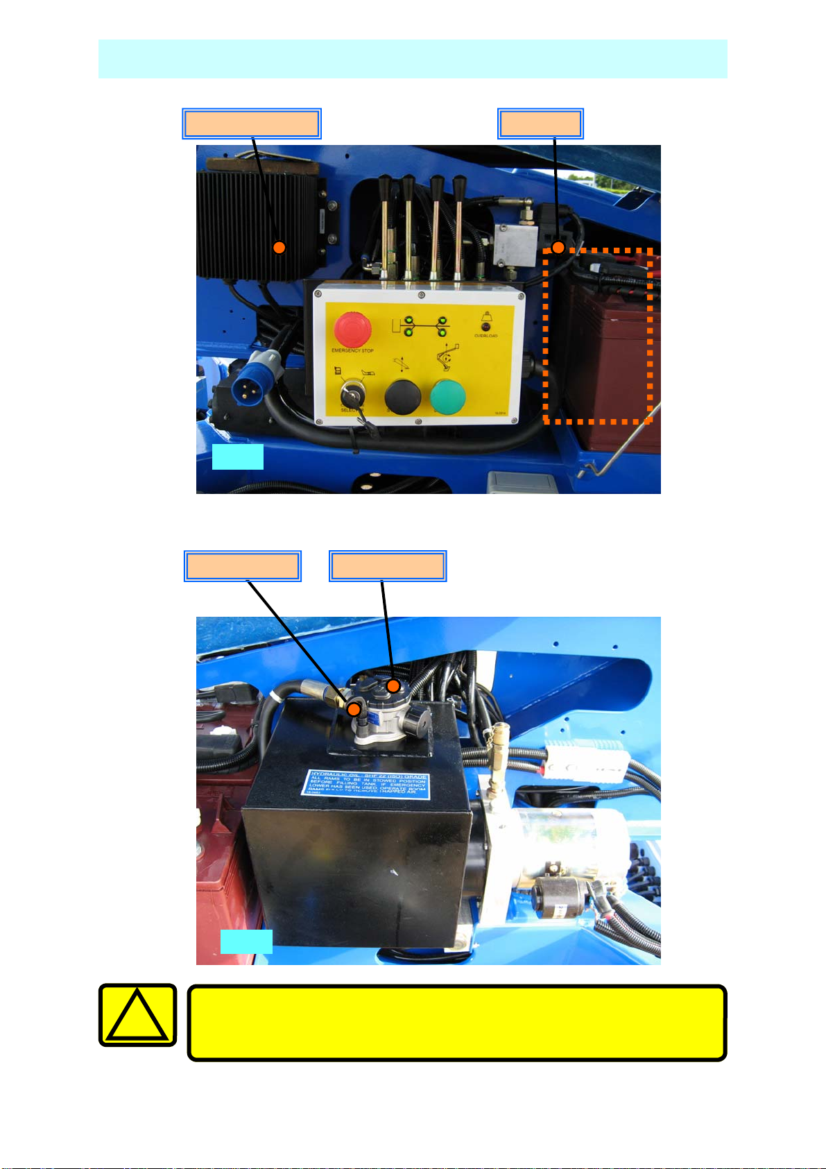
BATTERIES & POWER PACK
Batteries Battery Charger
Fig. 1
Dipstick
Oil Filler
!
Fig. 2
All extensions must be a minimum of 2.5mm², and no longer than
10m, due to possible voltage drop, which will damage the motor.
15
SETTING UP
1. Park the unit in an appropriate location at the workplace.
2. Apply the handbrake on the trailer and remove from the towing vehicle.
Do not attempt to set up the machine on steep slopes, ramps or
1
soft ground.
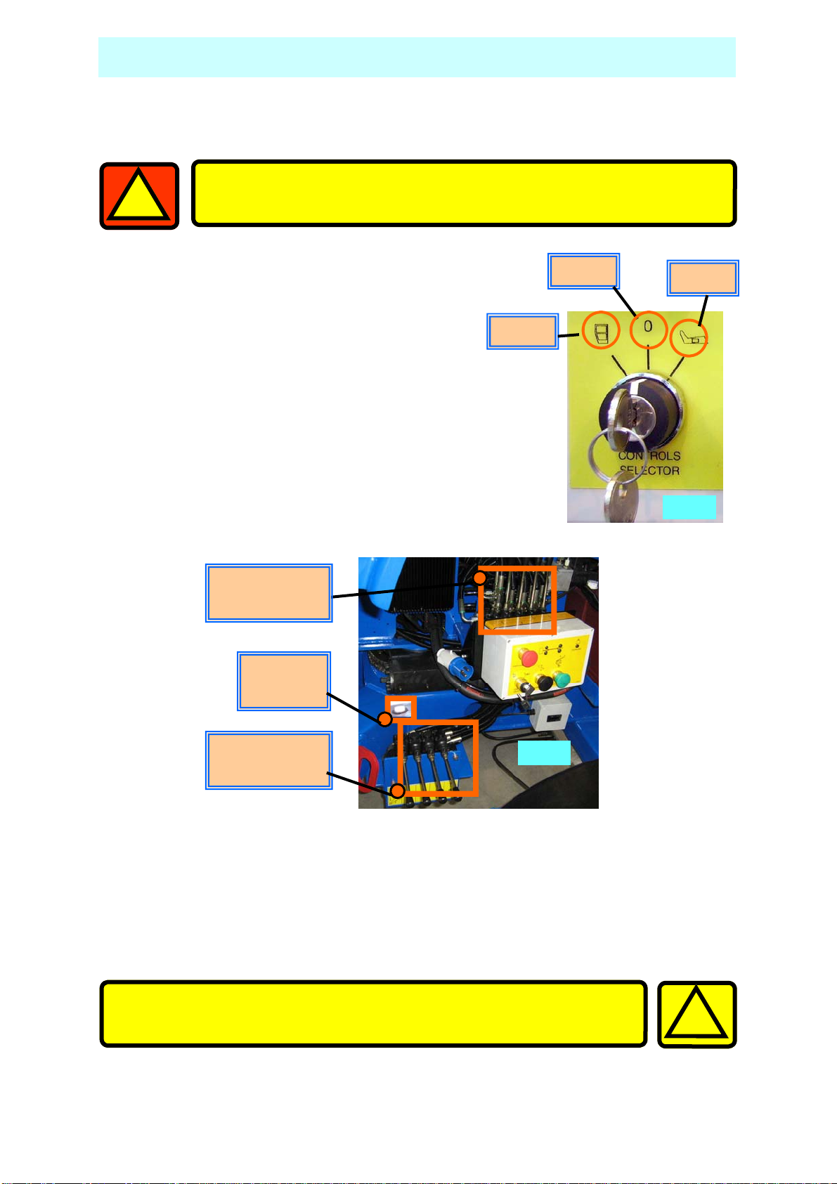
3. With platform key switch set to ’Ground’ (Fig 3)
lower the outriggers by keeping the
‘Outrigger Motor Run’ button (Fig 5) pushed
in, operate the appropriate
‘Outrigger control lever’ (Fig 4), until all
four are 25mm to 50mm from the ground.
Control Levers
Ground
Level
indicator
Basket
OFF
Ground
Fig. 3
Control Levers
Outriggers
4. Lower the Outriggers two at a time starting at the tow bar end (No’s 3&4) until
the jockey wheel just clears the ground.
5. Lower Outriggers 1&2 until the green LED display indicates that they are
under load. (Fig 6)
6. Repeat this sequence for Outriggers 3&4.
Take EXTREME care NOT to ground either the Basket, or the
Jockey Wheel during the next step.
Fig. 4
!
16
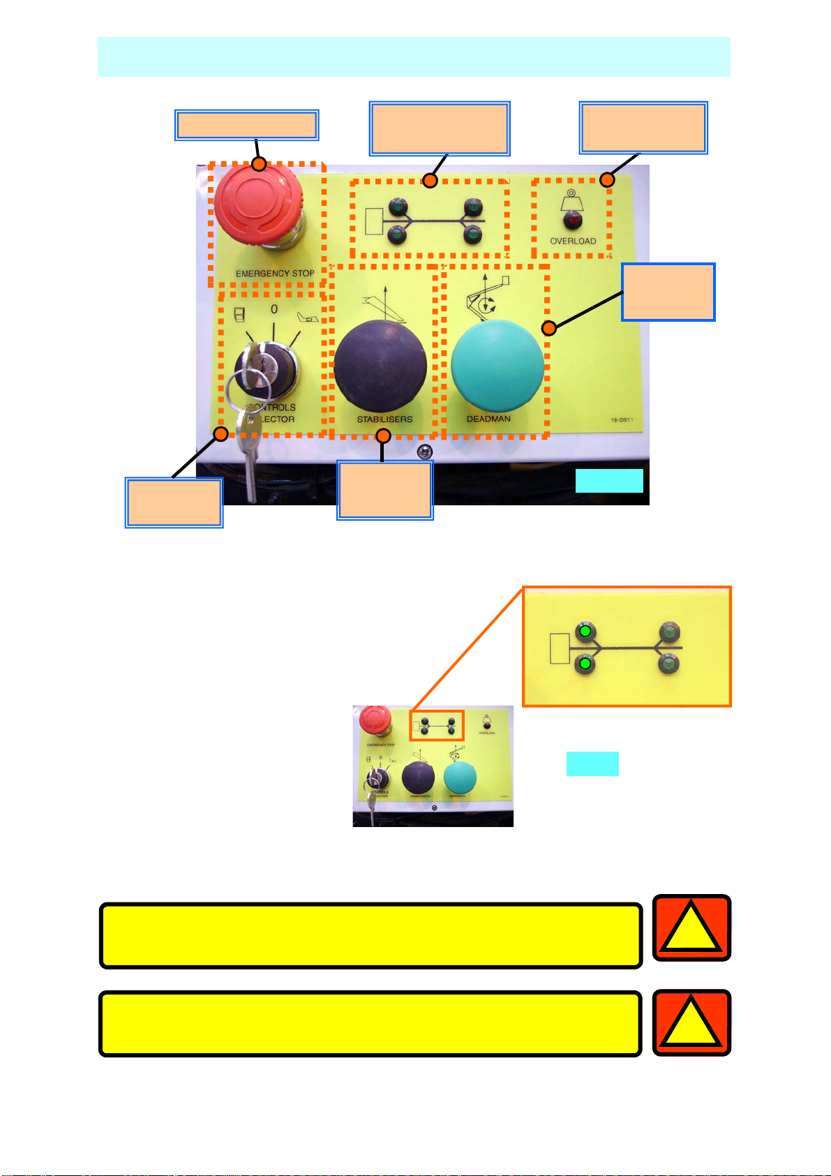
SETTING UP
Emergency Stop
Control
Selector
Fig. 5
Outrigger Load
Indicators
Motor Run
Outriggers
Cage Overload
Indicator
Motor Run
Booms
Fig. 5
7. By alternating from 1&2 to
3&4, carefully inch down
each pair of Outriggers
until all four Outriggers
are fully deployed, and the
wheels are well clear of the
ground.
8. Now, by using the Level
indicator (Fig.4), raise
opposite Outriggers until
the bubble and indicator
ring are concentric (i.e.,
the bubble rests in the
centre).
9. Check that each LED on the Ground Control panel is still illuminated. This in-
dicates that each foot is in firm contact with the supporting surface.
The unit is designed to operate on a supporting surface of
minimum bearing strength of 50N/cm
2
.
Fig. 6
1
The maximum outrigger load is 10.3kN.
1
17
EXTENDING STRUCTURE
The SET-UP section of this manual MUST be completed before
extending the structure.
1. Remove and correctly stow the Transit Pins, from both the Upper and Lower
Booms.
2. At the Ground Control Station, turn the key to ‘Basket’ (See point #6.)
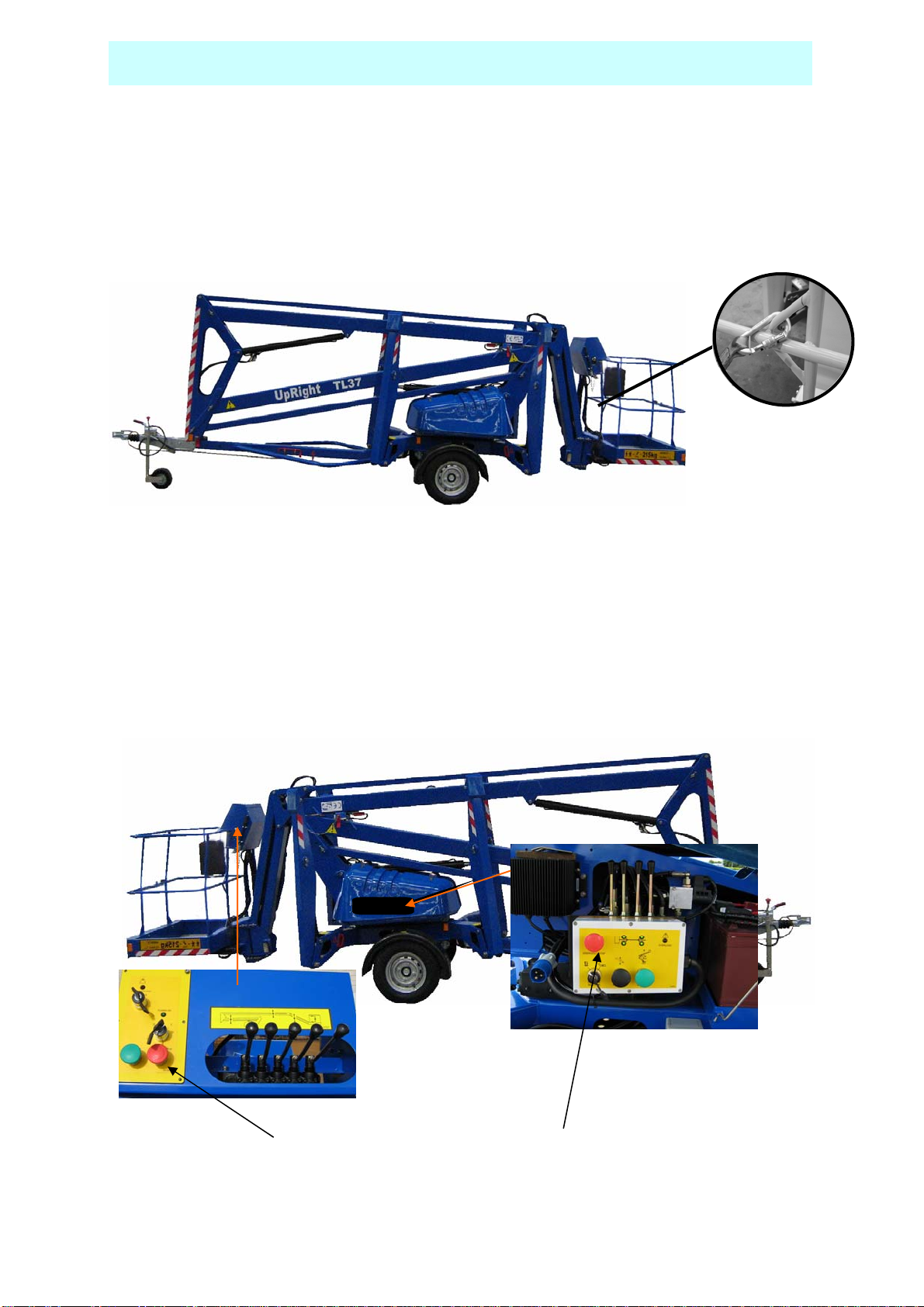
3. Climb into the basket. Check
that all Emergency Stop Switches
are released (twisting release).
The platform may now be raised,
lowered or slewed in any
direction by operating the
control levers at the basket,
whilst depressing the motor run
button (DEADMAN).
4. Explanation of the Basket Control Station, Directional Control Levers
18
Raise
Lower
Lower
Lower
Slew
Turret
Slew
Turret
Raise
Upper
Lower
Upper
Raise
Flick
Lower
Flick
Slew
Basket
Slew
Basket
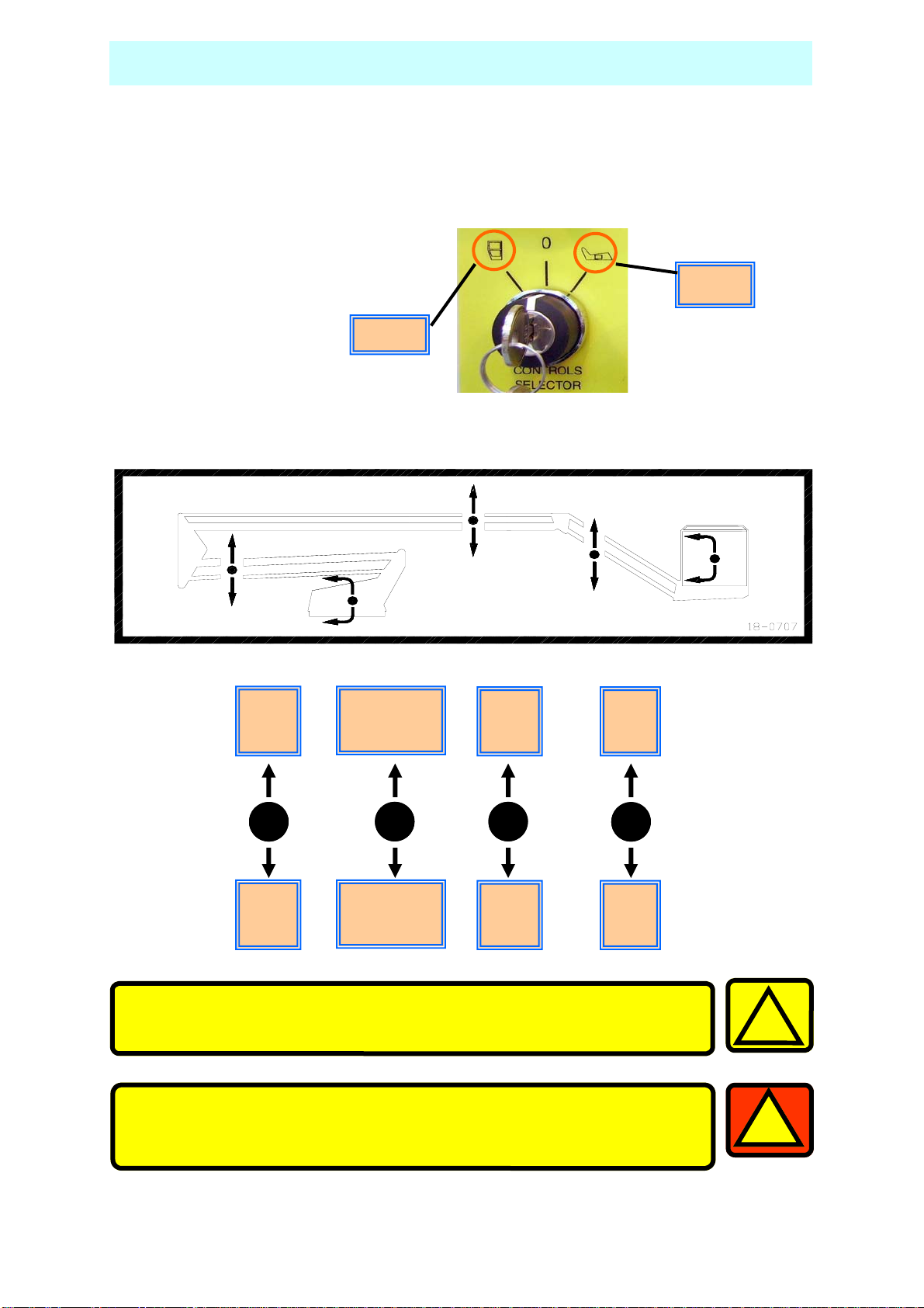
EXTENDING STRUCTURE
5. A duplicate set of controls (excluding Slew Basket) is mounted on the Slew
Turret under the right hand side cover, which allows the platform to be
operated from the Ground.
6. At the Ground Control Station, turn the key to ‘Ground’.
Basket
7. Explanation of the Ground Control Station, Directional Control Levers
Ground
Raise
Lower
Boom
Lower
Lower
Boom
Slew
Turret
Anticlockwise
Slew
Turret
Clockwise
Raise
Upper
Boom
Lower
Upper
Boom
Raise
Flick
Boom
Lower
Flick
Boom
Take EXTREME care when slewing both basket and turret, at
low levels.
Before raising, ensure there are no overhead obstructions or
power cables and the outriggers are properly extended and
secure.
!
1
19
SAFETY HARNESS & EMERGENCY CONTROLS
1. In accordance with IPAF recommendations, UpRight recommend the use of a
Full Body Harness with an adjustable lanyard is used when operation from
the basket.
2. The lanyard length should be as short as possible.
3. A permanent anchoring attachment point is provided in the basket for fixing
the harness.
EMERGENCY CONTROLS
1. Emergency Stop
Emergency Stop buttons are fitted on the machine to stop the motor in an
emergency.
There are 2 Emergency Stop Buttons, one in the basket, and one on the
ground control panel.
20
The emergency stops are ‘Reset’ by twisting.
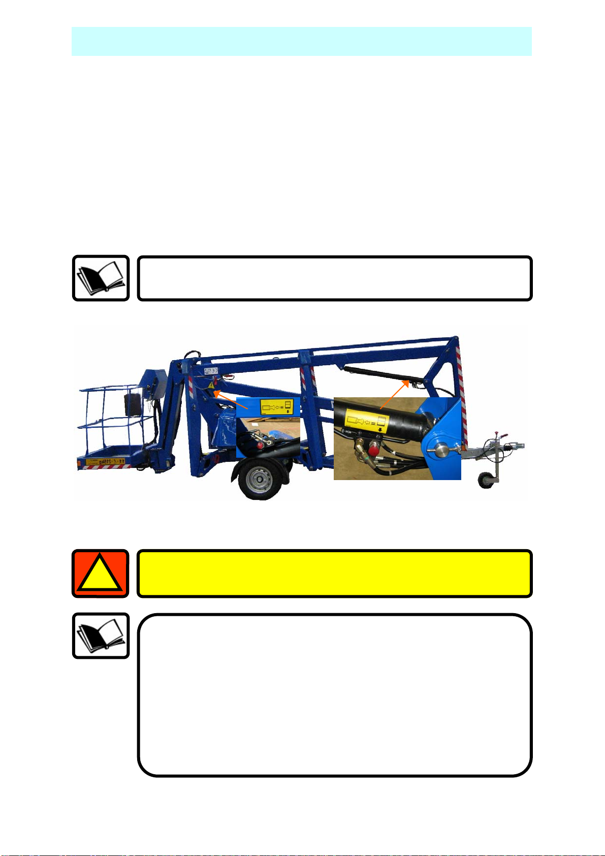
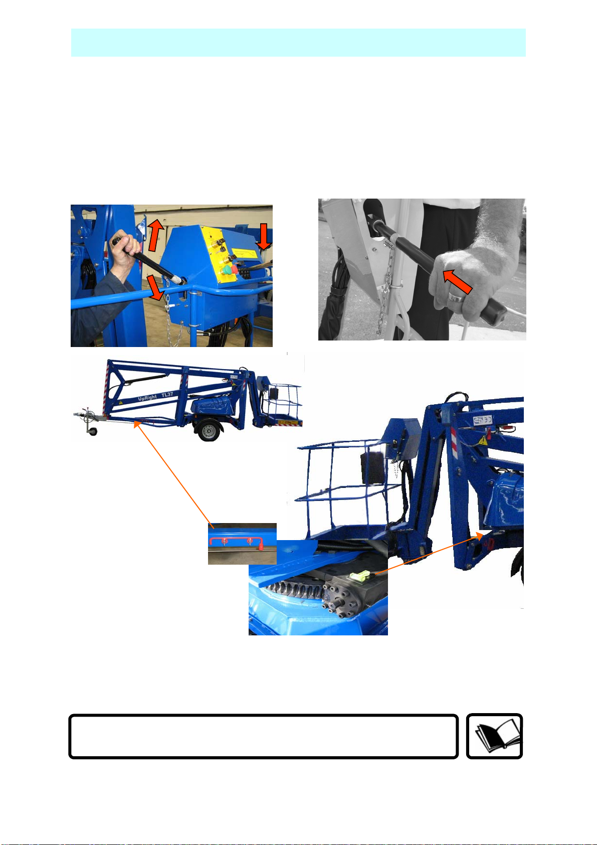
2. Emergency Lower.
In the event of a power failure, There are two ways of Safely lowering the
basket.
Emergency Lowering, method one
If you are able to get assistance from the ground they can lower both booms
by pressing the Emergency Lower Valve on the ram.
Open the Lower Ram valve first to facilitate access to the Top Ram valve.
Each emergency lower valve will automatically close when the
handle is released.
EMERGENCY CONTROLS
1
If the Emergency Lower is used due to a machine defect, DO NOT use
the machine, Contact your local UpRight representative.
If the Emergency Lower is used, The TOP and BOTTOM BOOMS must
be fully extended then fully lowered before work can continue.
After Emergency lowering, any further POWERED lowering could
cause an AIRLOCK in the hydraulic system.
This could cause the Hydraulic operations to Fail.
ALL BOOMS MUST BE FULLY EXTENDED/RAISED, THEN LOWERED
BEFORE WORK CAN RECOMMENCE.
21
EMERGENCY CONTROLS
Emergency Lowering, method two.
You can operate the hand pump in the cage and operate the lowering boom
functions.
To operate the hand pump, simply insert the lever into the pump shaft,
move a control lever to the required direction of movement, and operate
the hand pump. When the machine starts to lower, continue depressing the
control lever.
3. EMERGENCY SLEW.
In the event of a power failure, the machine may be manually slewed by
moving the base control slew lever in the desired direction and manually
indexing the Slew Platform by means of ratchet on the shaft of the Slew
Gearbox.
Vigorous pumping is required to lower and operate the slew.
22
EMERGENCY CONTROLS
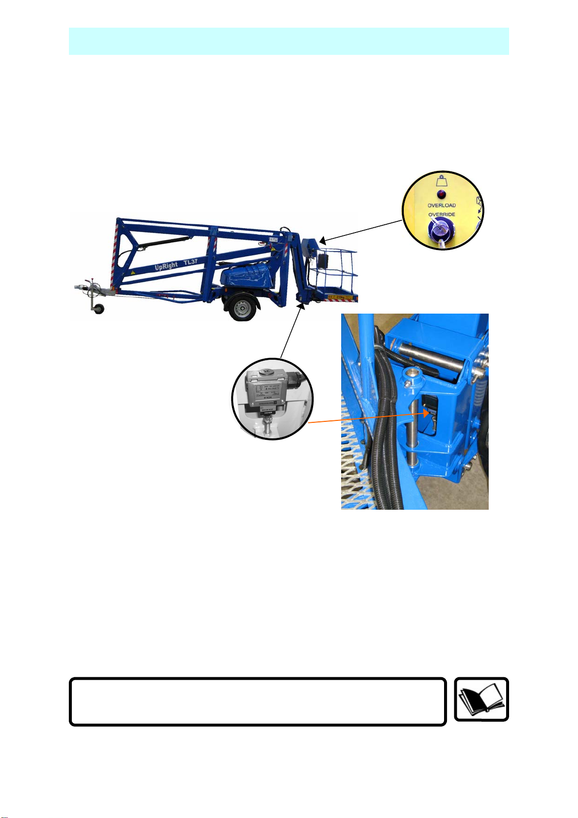
4. CAGE OVERLOAD.
In the event of the cage being overloaded, an audible alarm will sound and
the cage controls will cut out.
To re-start, enough load must be removed from the cage so that the
alarm stops sounding.
In cases where the overload can not be immediatley removed or the cage
has fouled, then the overload override selector switch can be used to move
the platform to a safe position so that the overload can safely removed.
The Key, Motor Run/Deadman and a Control Lever must be
operated at the same time to effect this action
23
EMERGENCY CONTROLS
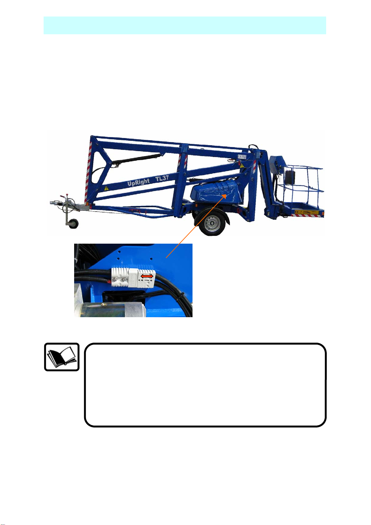
4. EMERGENCY BATTERY ISOLATING PLUG
Disconnecting this plug will isolate the batteries from the powerpack
and operating circuits.
24
Before operating this machine, it is important that both the
Operator and another responsible person on site, is aware of the
position and function of the following:
A) Emergency Stop Buttons.
B) Emergency Lowering Buttons.
C) Emergency Slew Drive Shaft.
D) Battery Isolating Plug.
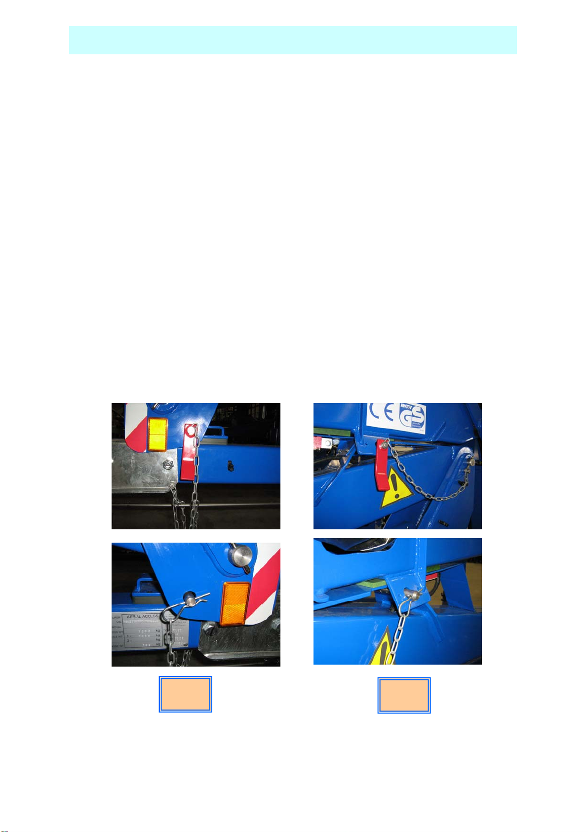
STOWING THE MACHINE
1. Fully lower all the booms.
2. Engage the Transit Pins, and lock in place using ‘R’ clip.
3. With platform keyswitch set to ‘Ground’:
Raise the outriggers by simultaneously depressing the ‘MOTOR RUN
Outrigger’ button and using the appropriate control levers, two at a time,
alternating between the cage and tow bar end until the road wheels are in
contact with the ground.
Only when the road wheels are in contact with the ground should the unit be
lowered further until the jockey wheel makes contact with the supporting
surface.
Now fully raise the outriggers until they are in the stowed position.
Switch off the platform and ensure all loose items/covers are secure before
towing the unit.
The machine is now ready for transportation.
TRANSPORT PIN LOCATIONS – SHOWN READY FOR TRANSPORT
Lower
Boom
Upper
Boom
25
MAINTENANCE
The unit must have a thorough inspection carried out every 6
months in accordance with LOLER Regulations 1998 and a
1
!
Daily Checks.
1. Damaged or Loose Fittings.
Visually Inspect the machine for signs of wear and tear, damage, loose or
missing parts.
2. Wheels.
Check tyres are at the correct pressure, 55 psi (3.8 bar) and that the
wheel nuts are tightened using the correct torque setting (100Nm).
3. Hydraulic fluid.
The hydraulic oil tank is located underneath the slew cover on the left
hand side of the machine (looking from the cage end) .With the booms and
outriggers in the transport position, the hydraulic oil level should be visible
between the upper and lower marks of the dipstick.
Top up with ISO Grade 22 hydraulic oil if necessary.
Certificate of Thorough Inspection produced by a competent
person.
Always ensure the machine structure is in good, sound,
undamaged condition. Any inspection procedure is always aided
by keeping the machine clean.
NB. Do not steam clean the battery charger or electrical
components.
Do Not Overfill the Tank
4. Safety Switches.
Check all limit switch arms are free from damage and move easily.
With outriggers in transport position, it must not be possible to operate the
extending structure.
With outriggers deployed, under load and top or bottom boom raised
approximately 50mm, it must NOT be possible to operate the outrigger
controls.
The flick boom is not interlocked with the outriggers.
5. Emergency Stop Switches.
Emergency stop switches must operate correctly. Check that each stops the
machine’s controls and that restarting is prevented until all stop switches
are unlatched.
26
 Loading...