

Page 1

Operator’s
Manual
P/N 0172094
February,2001
Page 2
DANGER
The aerial platform is not electrically insulated. Death or serious injury can result
from contact with,or inadequate clearance from,an energized conductor.
Do not go closer than the minimum safe approach distance as defined by the Mini
mum Safe Approach Distance section in Chapter 3–Safety.
Regard all conductors as energized.
Allow for electrical wire sag and aerial platform sway.
If the platform, booms, or any part of the aerial platform contacts a high-voltage electrical
conductor, the entire machine can become electrically charged.
Ifthathappens,remain onthe machineand donot contactanyotherstructure orobject.This
includestheground, adjacentbuildings,poles,andany otherobjectsthat are notpartofthe
aerial platform.
Such contact could make your body a conductor to the other object, creating an electrical
shock hazard resulting in death or serious injury.
If an aerial platform is in contact with an energized conductor the platform operator must
warn groundpersonnelinthevicinityto stay away.Theirbodies can conduct electricity creating an electrical shock hazard resulting in death or serious injury.
Do not approach or leave the aerial platform until the electricity has been turned off.
Donot attempttooperatethe lowercontrolswhentheplatform,booms,oranypartof theae
rial platform isincontactwitha high-voltage electrical conductor or ifthereisanimmediate
danger of such contact.
Personnel on or near an aerial platform must be continuously aware of electrical hazards,
recognizingthat deathor seriousinjurycanresultfromcontactwithanenergizedconductor.
-
-
Battery posts, terminals and related accessories contain
lead and lead components, chemicals knownto the State
of California to cause cancer and birthdefects or other
reproductive harm. Wash hands after handling.
TB37 – 0172094
Page 3

Table of Contents
Chapter 1. Introduction
Aerial Platform Features. . . . . . . . . . . . . . . . . . . . . 1-1
Options . . . . . . . . . . . . . . . . . . . . . . . . . . . . . . . . . . 1-1
Operator’s Manual . . . . . . . . . . . . . . . . . . . . . . . . . 1-1
Safety Alerts . . . . . . . . . . . . . . . . . . . . . . . . . . . 1-1
Notes . . . . . . . . . . . . . . . . . . . . . . . . . . . . . . . . . 1-2
Operation . . . . . . . . . . . . . . . . . . . . . . . . . . . . . . . . 1-2
Maintenance. . . . . . . . . . . . . . . . . . . . . . . . . . . . . . 1-2
Manual of Responsibilities . . . . . . . . . . . . . . . . . . . 1-2
Additional Information. . . . . . . . . . . . . . . . . . . . . . . 1-2
Chapter 2. Specifications
Component Identification . . . . . . . . . . . . . . . . . . . . 2-1
Working Envelope. . . . . . . . . . . . . . . . . . . . . . . . . . 2-2
General Specifications . . . . . . . . . . . . . . . . . . . . . . 2-3
Engine Specifications . . . . . . . . . . . . . . . . . . . . . . . 2-4
Engine Oil Viscosity. . . . . . . . . . . . . . . . . . . . . . 2-4
Chapter 3. Safety
Electrocution Hazards . . . . . . . . . . . . . . . . . . . . . . 3-1
Minimum Safe Approach Distance . . . . . . . . . . 3-1
Prestart Inspection . . . . . . . . . . . . . . . . . . . . . . . . . 3-2
Work Place
Inspection and Practices . . . . . . . . . . . . . . . . . . . . 3-2
Operation . . . . . . . . . . . . . . . . . . . . . . . . . . . . . . . . 3-2
Tip-Over and Falling Hazards. . . . . . . . . . . . . . . . . 3-2
Electrical System . . . . . . . . . . . . . . . . . . . . . . . . . . 3-3
Hydraulic System . . . . . . . . . . . . . . . . . . . . . . . . . . 3-3
Engine and Fuel
Handling Precautions . . . . . . . . . . . . . . . . . . . . . . . 3-3
Placards and Decals. . . . . . . . . . . . . . . . . . . . . . . . 3-4
Chapter 4. Safety Devices
Emergency Stop Controls. . . . . . . . . . . . . . . . . . . . 4-1
Emergency Power System . . . . . . . . . . . . . . . . . . . 4-1
Emergency Lowering Knob . . . . . . . . . . . . . . . . . . 4-1
Ground Controls Switch . . . . . . . . . . . . . . . . . . . . . 4-2
Platform Foot Switch. . . . . . . . . . . . . . . . . . . . . . . . 4-2
Guardrails. . . . . . . . . . . . . . . . . . . . . . . . . . . . . . . . 4-2
Lanyard Anchors. . . . . . . . . . . . . . . . . . . . . . . . . . . 4-2
Ground Fault Circuit Interrupter . . . . . . . . . . . . . . . 4-2
Tilt Alarm . . . . . . . . . . . . . . . . . . . . . . . . . . . . . . . . 4-2
Engine Protection Systems . . . . . . . . . . . . . . . . . . 4-2
High Engine Temperature Alarm . . . . . . . . . . . . 4-3
Low Oil Pressure Alarm. . . . . . . . . . . . . . . . . . . 4-3
Horn . . . . . . . . . . . . . . . . . . . . . . . . . . . . . . . . . . . . 4-3
Drive Motion Alarm. . . . . . . . . . . . . . . . . . . . . . . . . 4-3
Flashing Light . . . . . . . . . . . . . . . . . . . . . . . . . . . . . 4-3
Driving Lights . . . . . . . . . . . . . . . . . . . . . . . . . . . . . 4-3
Platform Work Lights . . . . . . . . . . . . . . . . . . . . . . . 4-3
Chapter 5. Gauges and Displays
Hour Meter . . . . . . . . . . . . . . . . . . . . . . . . . . . . . . . 5-1
Engine Temperature Gauge. . . . . . . . . . . . . . . . . . 5-1
Ammeter. . . . . . . . . . . . . . . . . . . . . . . . . . . . . . . . . 5-1
Engine Air Filter Gauge . . . . . . . . . . . . . . . . . . . . . 5-1
Fuel. . . . . . . . . . . . . . . . . . . . . . . . . . . . . . . . . . . . . 5-1
Engine Oil . . . . . . . . . . . . . . . . . . . . . . . . . . . . . . . . 5-2
Hydraulic Fluid Filter Gauge. . . . . . . . . . . . . . . . . . 5-2
Fluid Level and
Temperature Gauge . . . . . . . . . . . . . . . . . . . . . . . . 5-2
Chapter 6. Controls
Battery Disconnect Switch . . . . . . . . . . . . . . . . . . . 6-1
Lower Controls . . . . . . . . . . . . . . . . . . . . . . . . . . . . 6-1
Start Switch . . . . . . . . . . . . . . . . . . . . . . . . . . . . 6-1
Emergency Stop Switch . . . . . . . . . . . . . . . . . . 6-1
Controls Switch . . . . . . . . . . . . . . . . . . . . . . . . . 6-1
Ground Controls Switch. . . . . . . . . . . . . . . . . . . 6-1
Rotation Switch . . . . . . . . . . . . . . . . . . . . . . . . . 6-2
Boom Elevation Switch . . . . . . . . . . . . . . . . . . . 6-2
Boom Switch . . . . . . . . . . . . . . . . . . . . . . . . . . . 6-2
Platform Level Switch . . . . . . . . . . . . . . . . . . . . 6-2
Platform Rotator Switch. . . . . . . . . . . . . . . . . . . 6-2
Engine/Emergency Power Switch . . . . . . . . . . . 6-2
Throttle Switch. . . . . . . . . . . . . . . . . . . . . . . . . . 6-2
Fuel Switch . . . . . . . . . . . . . . . . . . . . . . . . . . . . 6-2
Circuit Breaker Reset Buttons . . . . . . . . . . . . . . . . 6-2
Upper Controls . . . . . . . . . . . . . . . . . . . . . . . . . . . . 6-3
Anti-Restart Master Switch . . . . . . . . . . . . . . . . 6-3
Emergency Stop Button. . . . . . . . . . . . . . . . . . . 6-3
Speed Knob. . . . . . . . . . . . . . . . . . . . . . . . . . . . 6-3
Swing Switch . . . . . . . . . . . . . . . . . . . . . . . . . . . 6-3
Boom Up/Down Switch . . . . . . . . . . . . . . . . . . . 6-3
Boom Extend/Retract Switch. . . . . . . . . . . . . . . 6-4
Level Switch. . . . . . . . . . . . . . . . . . . . . . . . . . . . 6-4
Steer Switch. . . . . . . . . . . . . . . . . . . . . . . . . . . . 6-4
Drive Joystick. . . . . . . . . . . . . . . . . . . . . . . . . . . 6-4
Drive Range Switch. . . . . . . . . . . . . . . . . . . . . . 6-4
Engine/Emergency Power Switch . . . . . . . . . . . 6-4
Throttle Switch. . . . . . . . . . . . . . . . . . . . . . . . . . 6-4
Platform Rotator Switch. . . . . . . . . . . . . . . . . . . 6-4
Horn Button . . . . . . . . . . . . . . . . . . . . . . . . . . . . 6-4
Platform Foot Switch. . . . . . . . . . . . . . . . . . . . . . . . 6-4
Machine/Generator Switch . . . . . . . . . . . . . . . . . . . 6-5
Dual Fuel . . . . . . . . . . . . . . . . . . . . . . . . . . . . . . . . 6-5
Driving and Platform Work Lights. . . . . . . . . . . . . . 6-5
Chapter 7. Prestart Inspection
Operator’s Manual . . . . . . . . . . . . . . . . . . . . . . . . . 7-1
Engine. . . . . . . . . . . . . . . . . . . . . . . . . . . . . . . . . . . 7-1
Oil Level. . . . . . . . . . . . . . . . . . . . . . . . . . . . . . . 7-1
Coolant . . . . . . . . . . . . . . . . . . . . . . . . . . . . . . . 7-1
Radiator . . . . . . . . . . . . . . . . . . . . . . . . . . . . . . . 7-1
Fuel Tank. . . . . . . . . . . . . . . . . . . . . . . . . . . . . . 7-2
Fuel Line . . . . . . . . . . . . . . . . . . . . . . . . . . . . . . 7-2
Air Filter . . . . . . . . . . . . . . . . . . . . . . . . . . . . . . . 7-2
Charging System . . . . . . . . . . . . . . . . . . . . . . . 7-2
Cold Weather Start Kit—Block Heater . . . . . . . 7-3
TB37 – 0172094
Page 4

Table of Contents
Electrical System . . . . . . . . . . . . . . . . . . . . . . . . . . 7-3
Emergency Power Battery. . . . . . . . . . . . . . . . . 7-3
Battery Fluid Level. . . . . . . . . . . . . . . . . . . . . . . 7-3
Battery Terminals. . . . . . . . . . . . . . . . . . . . . . . . 7-3
Cables and Wiring Harness. . . . . . . . . . . . . . . . 7-3
Hydraulic System . . . . . . . . . . . . . . . . . . . . . . . . . . 7-4
Fluid Level . . . . . . . . . . . . . . . . . . . . . . . . . . . . . 7-4
Fluid Filter . . . . . . . . . . . . . . . . . . . . . . . . . . . . . 7-4
Hoses, Tubes, and Fittings . . . . . . . . . . . . . . . . 7-4
Tires and Wheels . . . . . . . . . . . . . . . . . . . . . . . . . . 7-4
Air Filled. . . . . . . . . . . . . . . . . . . . . . . . . . . . . . . 7-5
Foam Filled . . . . . . . . . . . . . . . . . . . . . . . . . . . . 7-5
Lower Control Station. . . . . . . . . . . . . . . . . . . . . . . 7-5
Operating Controls. . . . . . . . . . . . . . . . . . . . . . . 7-5
Emergency Stop . . . . . . . . . . . . . . . . . . . . . . . . 7-5
Emergency Power . . . . . . . . . . . . . . . . . . . . . . . 7-5
Emergency Lowering . . . . . . . . . . . . . . . . . . . . . . . 7-6
Level Sensor. . . . . . . . . . . . . . . . . . . . . . . . . . . . . . 7-6
Flashing Light . . . . . . . . . . . . . . . . . . . . . . . . . . . . . 7-6
Sandblast Protection Kit. . . . . . . . . . . . . . . . . . . . . 7-6
Structures . . . . . . . . . . . . . . . . . . . . . . . . . . . . . . . . 7-7
Weldments. . . . . . . . . . . . . . . . . . . . . . . . . . . . . 7-7
Slide Pads . . . . . . . . . . . . . . . . . . . . . . . . . . . . . 7-7
Fasteners. . . . . . . . . . . . . . . . . . . . . . . . . . . . . . 7-7
Upper Control Station. . . . . . . . . . . . . . . . . . . . . . . 7-7
Guardrail System. . . . . . . . . . . . . . . . . . . . . . . . 7-7
Lanyard Anchors . . . . . . . . . . . . . . . . . . . . . . . . 7-8
Operating Controls. . . . . . . . . . . . . . . . . . . . . . . 7-8
Emergency Stop . . . . . . . . . . . . . . . . . . . . . . . . 7-8
Emergency Power . . . . . . . . . . . . . . . . . . . . . . . 7-8
Horn. . . . . . . . . . . . . . . . . . . . . . . . . . . . . . . . . . 7-8
Electrical Power Outlet . . . . . . . . . . . . . . . . . . . 7-8
Drive Motion Alarm . . . . . . . . . . . . . . . . . . . . . . 7-9
Driving and Work Lights . . . . . . . . . . . . . . . . . . 7-9
Platform Control Cover . . . . . . . . . . . . . . . . . . . 7-9
Tow Kit . . . . . . . . . . . . . . . . . . . . . . . . . . . . . . . . . . 7-9
Placards and Decals. . . . . . . . . . . . . . . . . . . . . . . . 7-9
Prestart Inspection Check List . . . . . . . . . . . . . . . 7-13
Chapter 8. Operation
Cold Weather Start-Up. . . . . . . . . . . . . . . . . . . . . . 8-1
Engine Cold Weather Start Kit . . . . . . . . . . . . . 8-1
Ford—Block Heater . . . . . . . . . . . . . . . . . . . 8-1
Deutz—Manifold Preheater . . . . . . . . . . . . . 8-1
Hydraulic System
Cold Weather Warm-Up . . . . . . . . . . . . . . . . . . 8-1
Preparing for Operation . . . . . . . . . . . . . . . . . . . . . 8-2
Lower Controls . . . . . . . . . . . . . . . . . . . . . . . . . . . . 8-2
Upper Controls . . . . . . . . . . . . . . . . . . . . . . . . . . . . 8-2
Boom Operation. . . . . . . . . . . . . . . . . . . . . . . . . 8-2
Driving and Steering . . . . . . . . . . . . . . . . . . . . . 8-3
Drive Speeds . . . . . . . . . . . . . . . . . . . . . . . . 8-3
Four-Wheel Drive . . . . . . . . . . . . . . . . . . . . . . . . . . 8-4
Electrical Power Outlet . . . . . . . . . . . . . . . . . . . . . . 8-4
AC Generator . . . . . . . . . . . . . . . . . . . . . . . . . . . . . 8-4
Dual Fuel . . . . . . . . . . . . . . . . . . . . . . . . . . . . . . . . 8-4
Driving Lights . . . . . . . . . . . . . . . . . . . . . . . . . . . . . 8-4
Platform Work Lights . . . . . . . . . . . . . . . . . . . . . . . 8-5
Chapter 9. Stowing and Transporting
Stowing. . . . . . . . . . . . . . . . . . . . . . . . . . . . . . . . . . 9-1
Transporting . . . . . . . . . . . . . . . . . . . . . . . . . . . . . . 9-1
Driving . . . . . . . . . . . . . . . . . . . . . . . . . . . . . . . . 9-1
Winching . . . . . . . . . . . . . . . . . . . . . . . . . . . . . . 9-2
Hoisting . . . . . . . . . . . . . . . . . . . . . . . . . . . . . . . 9-2
Securing for Transport. . . . . . . . . . . . . . . . . . . . 9-3
Chapter 10. Emergency Operation
Emergency Power System . . . . . . . . . . . . . . . . . . 10-1
Lower Controls. . . . . . . . . . . . . . . . . . . . . . . . . 10-1
Upper Controls. . . . . . . . . . . . . . . . . . . . . . . . . 10-1
Emergency Lowering . . . . . . . . . . . . . . . . . . . . . . 10-2
Towing. . . . . . . . . . . . . . . . . . . . . . . . . . . . . . . . . . 10-2
Chapter 11. Troubleshooting
Troubleshooting Chart . . . . . . . . . . . . . . . . . . . . . 11-1
Appendix A. Glossary
TB37 – 0172094
Page 5

Chapter 1. Introduction
Aerial Platform Features
The aerial platform is a boom-supported elevating work
platform used to raise personnel, their tools, and mate
rial to the workstation. The booms are raised and low
ered with hydraulic cylinders. Hydraulic motors on the
drivewheels providepowerto movetheaerialplatform.
The standard machine includes the following features.
●
Proportional drive control
●
Pneumatic tires
●
Gasoline liquid cooled engine
●
High engine temperature shut down
●
Low oil pressure shut down
●
Hour meter
●
Ammeter
●
Coolant temperature gauge
●
Hydraulic oil level and temperature gauges
●
Battery operated emergency power system
●
Manual lowering valve
●
Tilt alar m
●
360° continuous turntable rotation
●
Tie-down lugs
●
Lifting lugs
●
AC electrical outlet with GFCI at platform
●
5′ steel 600 lb capacity platform
●
Gravity gate
●
Five year warranty
The aerial platform has been manufacturedtoconform
toallapplicablerequirements of the followingorganiza
tions.
●
Occupational Safety and Health Administration
(OSHA)
●
American National Standards Institute (ANSI)
●
Canadian Standards Association (CSA)
Options
Thefollowingoptionsmaybeprovidedonthe machine.
●
Four-wheel drive
●
Road tread tires
●
Foam filled tires
●
Drive motion alarm
●
Diesel air cooled engine
●
Dual fuel with 12 gallon gasoline tank
●
Dual fuel with 20 gallon gasoline tank
●
Flashing light
●
-
-
Driving lights
●
Platform work lights-flood or halogen
●
Horn
●
Platform control cover
●
Swinging platform gate
●
8′ aluminum 600 lb capacity platform
●
8′ aluminum 600 lb capacity platform with
guardrails
●
8′ steel 500 lb capacity platform
●
5′ aluminum 650 lb platform
●
5′ steel 600 lb platform
●
Sandblast protection kit
●
Cold weather start kit
●
Tow kit
●
AC generator
Operator’s Manual
This manual provides information for safe and proper
operationofthe aerial platform.Because it coversmore
than one model,somefiguresmayonly represent what
isactuallyon themachine.Readand understandtheinformation in this Operator’s Manual before operating
the aerial platform on the job.
Additional copies of this manual may be ordered from
Snorkel. Supply the model and manual part number
from the front cover to assure that the correct manual
will be supplied.
All information in this manual is based on the latest
-
product information at the time of publication. Snorkel
reserves the right to makeproductchangesat any time
without obligation.
Safety Alerts
A safetyalert symbol is used throughout this manual to
indicate danger and caution instructions.Follow these
instructions to reduce the likelihood of personal injury
andpropertydamage.Thetermsdanger andcaution in
dicate varying degrees of personal injury or property
damagethat canresult iftheinstructionis notfollowed.
DANGER
Indicates asituationwhich if not avoided canresult
in death or serious injury.
CAUTION
Indicates asituationwhich if not avoided canresult
in minor injury or property damage.
-
TB37 – 0172094 page 1 - 1
Page 6

Chapter 1. Introduction
Notes
Notes are used to provide special information or helpful
hints to assist in aerial platform operation, but do not indi
cate a hazardous situation.
Operation
The aerial platform has built-in safety featuresand has
beenfactorytested forcompliancewith Snorkel specifi
cations and industr y standards. However, any person
nellifting aerialplatformcanbepotentiallydangerousin
the hands of untrained or careless operators.
DANGER
The potential for an accident increases when the
aerial platform is operated by personnel who are
not trained and authorized. Death or serious injury
can result from such accidents. Read and under
stand the information in this manual and on the
placards and decals on the machine before operat
ing the aerial platform on the job.
Training is essentialandmustbe performed by a quali
fiedperson.Becomeproficientin knowledgeandactual
operation before using the aerial platform on the job.
Youmustbetrainedandauthorizedtoperformanyfunctions of the aer ial platform. Operation of the aerial platform must be within the scope of the machine
specifications.
The operator bears ultimate responsibility for following
all manufacturer’s instructions and warnings, regulationsandsafetyrulesoftheir employerand/orany state
or federal law.
Maintenance
Every person who maintains, inspects,tests,orrepairs
the aerial platform must be qualified to do so.Following
the daily prestart inspection in this Operator’s Manual
will help keep the aerial platform in optimum working
condition. Other maintenance functions must be per
formed by maintenance personnel who are qualified to
work on the aerial platform.
Do not modify this aerial platform without prior written
consent of the Snorkel Engineering Department.Modi
ficationmayvoid thewarranty, adverselyaffectstability,
or affect the operational characteristics of the aerial
platform.
-
-
Manual of Responsibilities
All owners and users of the aerial platform must read,
understand, and comply with all applicable regulations.
Ultimate compliance to OSHA regulations is the re
sponsibility of the user and their employer.
ANSI publications clearly identify the responsibilities of
all personnel who may be involved with the aerial plat
form. A reprint of the “Manual of Responsibilities for
-
Dealers, Owners, Users, Operators, Lessors and Les
sees of ANSI/SIA A92.5-1992 Boom-Supported Ele
-
vating Work Platforms” is available from Snor kel
dealers or from the factory upon request.
Copies are also available from:
Scaffold Industry Association
20335 Ventura Blvd. Suite 310
Woodland Hills, CA 91364-2471 USA
Additional Information
For additional information contact your local dealer or
Snorkel at:
Snorkel Inter national, Inc.
P.O.Box 1160
St. Joseph, MO 64502-1160 USA
816-364-0317
http://www.snorkelusa.com
-
-
-
-
-
-
page 1 - 2 TB37 – 0172094
Page 7
Chapter 2. Specifications
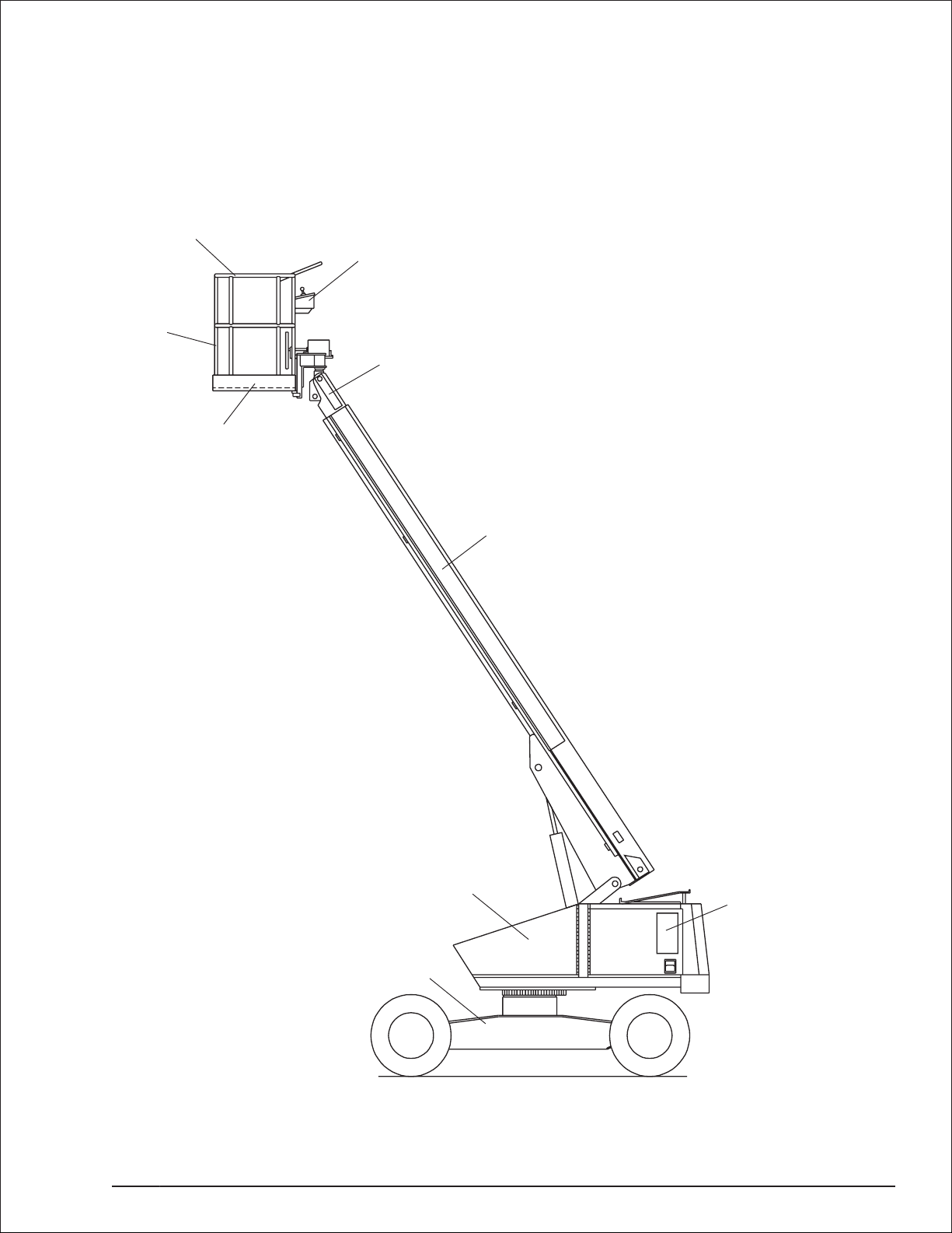
Component Identification
Guardrails
Upper Controls
latform
Toeboards
Tip Boom
Main Boom
Turntable
Chassis
Rear
TB37 – 0172094 page 2 - 1
Front (Steer)
Lower Controls
Page 8
Chapter 2. Specifications
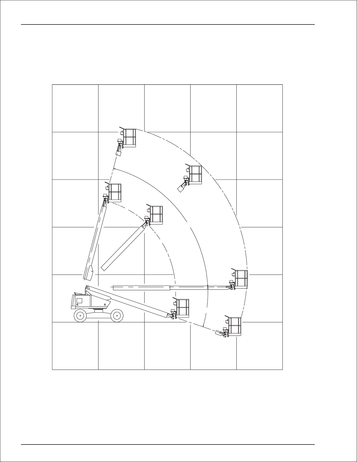
Working Envelope
50
(15.2)
40
(12.2)
30
(9.1)
20
(6.1)
10
(3.0)
0
10
(3.0)
010
(3.0)
75°
20
(6.1)
18°
30
(9.1)
Feet
(Meters)
page 2 - 2 TB37 – 0172094
Page 9

General Specifications
Chapter 2. Specifications
Aerial Platform
Working height 43′ (13.1 m)
Maximum platform height 37′ (11.3 m)
Horizontal reach 32′ (9.8 m)
Main boom
Articulation -18° to +75°
Extension 12′ (3.6 m)
Turntable rotation 360° continuous
Turning radius, inside 5′ 2″ (1.6 m)
Wheelbase 8′ (2.4 m)
Ground clearance 10″ (25 cm)
Maximum wheel load 5,500 lbs (2,495 kg)
Maximum ground pressure 54 psi (3.8 kg/cm²)
Weight, GVW
Approximate 10,500 lbs (4,763 kg)
Stowed width 7′ 11.5″ (2.4 m)
Stowed length 26′ 2″ (8 m)
Stowed height 7′ 6″ (2.3 m)
Platform
Dimensions
Standard 30″ x60″ (76 cm x 152 cm)
Optional 30″ x96″ (76 cm x 244 cm)
Guardrail height 30″ x96″
Rated work load
Standard 600 lb (272 kg)
Optional 500 lb (227 kg)
Optional 650 lb (295 kg)
Rotation 180°
Maximum number of occupants 2 people
Optional AC generator 120 V, 17.4 amp
Function Speed
Turntable rotation 90 to 100 seconds
Main boom
Up 40 to 45 seconds
Down 40 to 45 seconds
Extend 35 to 45 seconds
Retract 30 to 40 seconds
Platform rotation 16 to 20 seconds
Drive
High, booms stowed 3.0 mph (4.8 km/h)
Low, booms elevated 1.0 mph (1.6 km/h)
Drive System
Standard 2-wheel dr ive
Optional 4-wheel dr ive
Gradeability 25%
Tires, 10 ply
Pneumatic 12″ x 16.5″ (30 cm x 42 cm)
Flotation 15″ x 19.5″ (38 cm x 50 cm)
Foam filled Pneumatic or Flotation
Electrical System
Voltage 12 V DC negative chassis ground
Source
Gas engine 1 -12 V 600 CCA battery
Diesel engine 2 - 12 V 600 CCA batteries
Fluid recommended distilled water
Hydraulic System
Maximum pressure 2,500 psi (17,237 kPa)
Reservoir capacity 16.5 US gal (62.4 l)
System capacity 20 US gal (75.7 l)
Maximum operating temperature 200°F (93°C)
Hydraulic fluid recommended
Above 10°F (-13°C) Mobil DTE-13M
(ISO VG32)
Below 10°F (-13°C) Mobil DTE-11M
(ISO VG15)
Engine
Gasoline and/or LPG Ford VSG-413
Diesel Deutz F3L-1011
Fuel Tank Capacity
Gasoline or diesel 20 US gal (75.7 l)
LPG 43.5 lbs (19.7 kg)
Dual fuel gasoline 20 US gal (75.7 l)
12 US gal (45.4 l)
Ambient Air Temperature Operating Range
Fahrenheit 0°F to 110°F
Celsius -18°C to 43°C
Maximum Wind Speed
Gust or steady 28 mph (45 km/h)
TB37 – 0172094 page 2 - 3
Page 10
Chapter 2. Specifications
Engine Specifications
Ford VSG-413
Ford VSG-413
Fuel type Gasoline LPG Diesel
Deutz F3l-1011
Deutz F3l-1011
Fuel grade Unleaded gasoline 87
octane
Do not use gasoline
blends with more than 5%
methanol by volume, or
blends that do not contain
cosolvents and corrosion
inhibitors.
Commercial LP gas
DIN 51 601 (February 1986)
•
BS 2869: A1 and A2 (with A2
•
refer to Deutz manual about
sulfur content)
ASTM D 975-88: 1-D and 2-D
•
CEN EN 590 or DIN EN 590
•
NATO Code F-54 and F-75
•
For operating temperatures
•
below 32°F (0°C) use winter
grade diesel.
Displacement 79.3 cu. in.(1,300 cc) 125 cu. in. (2,049 cc)
Coolant 50% water/50% anti-freeze (ethelene glycol) Air
Operating temperature 160°F (71°C) to 190°F (88°C) 172°F (78°C) to 203°F (95°C)
Oil capacity 3.5 qt USA (3.25 l) 1.59 U.S. gal.(6.0 l)
Oil grade API: SG, SG/CC or SG/CD API: CD grades or higher
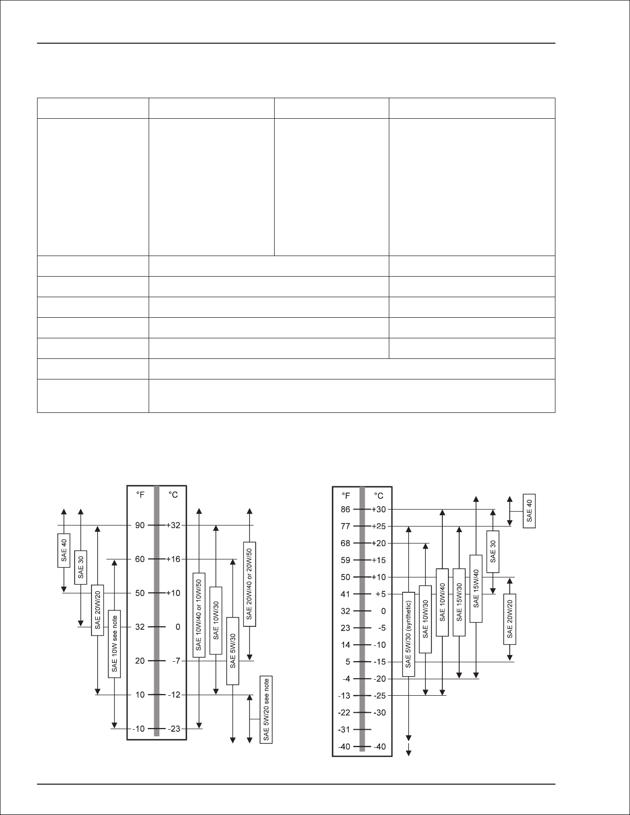
Oil viscosity See Engine Oil Viscosity
Running time One full tank of gas, diesel, or LPG will last for eight hours under normal working
conditions.
Engine Oil Viscosity
Ford VSG-413
Deutz F3l-1011
Single Viscosity Multi Viscosity
Note:
Not recommended for severe service, including high
RPM operation.
page 2 - 4 TB37 – 0172094
Only with engine oil preheating.
Page 11
Chapter 3. Safety
Knowledgeoftheinformationinthismanual,andproper
training, provide a basis for safely operating the aerial
platform.Know the location of all controls and howthey
operatetoactquicklyandresponsiblyin anemergency.
Safety devices reduce the likelihood of an accident.
Never disable, modify, or ignore any safety device.
Safety alerts in this manual indicate situations where
accidents may occur.
If any malfunction, hazard or potentially unsafe condi
tionrelatingtocapacity,intended use, orsafeoperation
is suspected, stop aerial platform operation and seek
assistance.
The operator bears ultimate responsibility for following
all manufacturer’s instructions and warnings, regula
tionsandsafetyrulesoftheir employerand/orany state
or federal law.
Electrocution Hazards
Theaerialplatform ismadeof metalcomponentsand is
not insulated. Regard all conductors as energized. Do
not operate outside during a thunderstorm.
Minimum Safe Approach Distance
Minimum safe approach distances to energized power
linesandtheir associatedpartsmustbeobservedwhile
operating the aerial platform.
DANGER
The aerial platform is not electrically insulated.
Deathor seriousinjurycan resultfromcontactwith,
or inadequate clearance from, an energized con
ductor.Do not go closer than the minimumsafeap
proach distance as defined by ANSI.
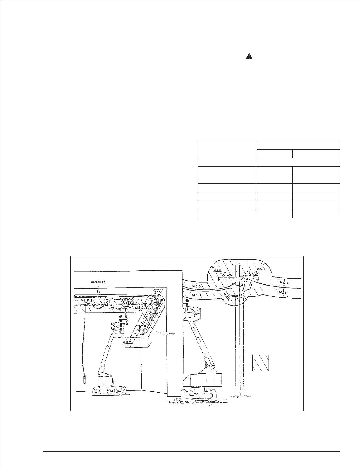
ANSI publications define minimum distances that must
be observed when working near bus bars and ener
gized power lines. Table 1 and Figure 3 are reprinted
courtesy of Scaffold Industry Association, ANSI/SIA
A92.5, page 23.
-
Voltage range
(phase to phase)
0 to 300V
Over 300V to 50kV
Over 50kV to 200kV
Over 200kV to 350kV
Over 350kV to 500kV
Over 500kV to 750kV
Over 750kV to 1000kV
Table 1—Minimum Safe Approach Distance
Minimum safe approach distance
(Feet) (Meters)
Avoid contact
10
15
20
25
35
45
-
-
-
3.05
4.60
6.10
7.62
10.67
13.72
Denotes
prohibited
zone
Figure 3—Minimum Safe Approach Distance
TB37 – 0172094 page 3 - 1
Page 12

Chapter 3. Safety
Prestart Inspection
Perform a prestart inspection before each shift as de
scribed in Chapter 7. Do not use the aerial platform on
thejob unlessyouaretrainedandauthorizedto doso.
Work Place
Inspection and Practices
Do not use the aerial platform as a ground connection
when welding. The welding ground clamp must be at
tachedtothe same structure thatisbeing welded.Elec
trical current flowcan be very intense, causingserious
internal damage to some components.
Inspect the area beforeand during aerial platform use.
Thefollowingaresomepotentialhazards thatmaybein
the work place.
●
Debris
●
Slopes
●
Drop-offs or holes
●
Bumps and floor obstructions
●
Overhead obstructions
●
Unauthorized persons
●
High voltage conductors
●
Wind and weather conditions
●
Inadequate surface and support to withstand load
forcesappliedby theaerialplatformin all operating
configurations
Beforeusing the aerial platforminany hazardous (classified) location, make certain it is approved and of the
typerequiredbyANSI/NFPA 505foruse in thatparticu
lar location.
Know and understand the job site traffic-flow patterns and
obey the flagmen, road signs, and signals.
While operatingtheaerialplatform,agoodsafety prac
ticeistohavequalifiedpersonnelinthe immediatewor k
area to:
●
Help in case of an emergency
●
Operate emergency controls as required
●
Watch for loss of control by platform operator
●
Warn the operator of any obstructions or hazards
that may not be obvious to them
●
Watch for soft terrain, sloping surfaces, drop-offs,
etc. where stability could be jeopardized
●
Watchfor bystandersandnever allowanyonetobe
under, or to reach through the booms while
operating the aerial platform
-
Pinch points may exist between moving compo
DANGER
nents. Death or serious injury can result from be
coming trapped between components, buildings,
structures, or other obstacles. Make sure there is
sufficient clearance around the machine before
moving thechassis,booms, or platform.Allow suffi
cient roomandtimetostop movement to avoidcon
-
tact with structures or other hazards.
Always look in the direction of movement. Drive with
careandat speeds compatiblewith the workplacecon
ditions.Usecautionwhendrivingoverrough ground,on
slopes,andwhenturning.Do not engage inanyform of
horseplay or permit riders any place other than in the
platform.
Secureallaccessories,containers,tools,and otherma
terials in the platform to preventthemfromaccidentally
falling or being kicked off the platform. Remove all ob
jects that do not belong in or on the aerial platform.
Never steady the platform by positioning it against an
other platform.Do not use boards, or other temporary
means to support or level the aerial platform.
Donotoperate the aerialplatformif it isdamagedor not
functioning properly. Qualified maintenance personnel
must correct the problembeforeputting the aerial platform back into service.
Operation
Usethreepoints of support whenenteringorexitingthe
platform. For example, use two hands and one foot
-
when climbing into the platform.
Never cover the platform floor grating or otherwise ob
struct your view below. Make sure the area below the
platform is free of personnel before lowering.
-
Keep both feet positioned firmly on the platform floor.
Operate the controls slowly and deliberately to avoid
jerky and erratic operation. Always stop the controls in
neutral before going in the opposite direction.
Donotdismount while theaerialplatformis in motionor
jump off the platform.
Properly stow the aerial platform and secure it against
unauthorizedoperationat theendof eachworkday,be
fore transporting, or if it is left unattended.
Tip-Over and Falling Hazards
Operatetheaer ial platform onlyona firm, flat, level sur
facecapableof withstanding all load forcesimposedby
the aerial platform in all operatingconditions.Raise the
boomsonly whenthe aerialplatform isonlevelground.
-
-
-
-
-
-
-
-
-
-
-
page 3 - 2 TB37 – 0172094
Page 13

Chapter 3. Safety
DANGER
The aerial platformcan tip over if it becomesunstable.
Death or serious injury can result from a tip-overacci
dent.Donotdriveorpositiontheaerialplatf ormforele
vateduse nearan ydrop-off,hole,slope,softor uneven
ground, or other tip-over hazard.
Allplatf ormoccupantsmustwearafallrestraintdevicecon
nected to a lanyard anchor point.
It isbestnotto transfer fromtheplatformtoanother struc
tureorfrom the structuretotheplatform, unlessthatis the
safest way to do the job.Judge each situation separately
takingthe workenvironment intoaccount.If itisnecessary
to transf er from the platform to another structure the fol
lowing guidelines apply:
1. Where possible, place the platform over a roof or
walking structure to do the transfer.
2. Transfer your anchorage from one structure to the
other before stepping across.
3. Remember that you might be transf erring to a struc
ture where
4. Use the platform entrance, do not climb over the
guardrails.
personal fall arrest
is required.
Electrical System
Charge the batteries in a well-ventilated area free of
flame, sparks, or other hazards that might cause fire or
-
explosion.
-
Donotoperateanyoftheaerialplatform functionswhile
the battery charger is plugged in.
-
Batteries give off hydrogen and oxygen that can
combineexplosively.Deathor seriousinjury canre
-
sult from a chemical explosion. Do not smoke or
permit open flames or sparks when checking the
batteries.
-
Battery acidcan damage theskinand eyes.Serious
infection orreactioncan result if medical treatment
is not given immediately. Wearfaceandeye protec
tion when working near the batteries.
Batteries contain sulfuric acid that can damage your
eyes or skin on contact. Wear a face shield, rubber
gloves, and protective clothing when wor king around
batteries. If acid contacts your eyes, flush immediately
with clear water and get medical attention. If acid contacts your skin, wash off immediately with clear water.
DANGER
-
-
Donotoperatetheaerial platforminwindyorgusty conditions. Do not add anything to the aerial platform that
will increase the wind loading such as billboards, banners, flags, etc.
Never operate the aerial platform without all parts of the
guardrail system in place and the gate closed.Makesure
that all protective guards, cowlings, and doors are securely fastened.
Donotexceed theplatformcapacity as indicatedonthe
platform rating placard on the platform. Do not carry
loads that extend beyond the platform guardrails without
prior written consent from Snorkel.
Do not operate the aerial platform from trucks, trailers,
railway cars, floating vessels, scaffolds, or similar
equipment unless the application is approvedinwriting
by Snorkel.
Do not usetheaerialplatformasacrane, hoist, jack,or
for anypurpose other than to position personnel, tools,
and materials.
Donotclimb ontheguardrails oruseladders, planks,or
other devices to extend or increase the work position
from the platform.
Take caretopre v entrope, electrical cords,andhoses, etc.,
from becoming caught in or on the aerial platform. If the
platform or booms becomes caught on an adjacent struc
tureorotherobstacleandispreventedfrom normalmotion,
reverse the control to free the platform. If control reversal
doesnotfreethe platform,ev acuatethe platform beforeat
tempting to free it.
Hydraulic System
The hydraulic system contains hoses with hydraulic
fluid under pressure.
DANGER
Hydraulic fluid escaping under pressure can have
enough force to inject fluid into the flesh. Serious
infection orreactioncan result if medical treatment
is notgivenimmediately.In caseofinjuryby escap
inghydraulic fluid,seekmedical attentionat once.
Do not place yourhandoranypart of yourbodyinfront
of escaping hydraulicfluid.Use a piece of cardboard or
wood to search for hydraulic leaks.
Engine and Fuel
Handling Precautions
Refer to the engine manufacturer’s Operator’s Manual
for complete information on safe engine operation,
maintenance, and specifications.
DANGER
Engine exhaust contains carbon monoxide, a poi
sonous gas that is invisible and odorless.
Breathing engine exhaust fumes can cause death
or serious illness. Do not run the engine in an en
-
closed area or indoors without adequate ventila
tion.
-
Operate dual fuel machines on LPG fuel when indoors
to reduce exhaust fumes and carbon monoxide.
-
-
-
-
TB37 – 0172094 page 3 - 3
Page 14

Chapter 3. Safety
Be careful not to run the diesel fuel tank empty. Bleed
the fuel system if air enters the lines between the tank
and the injection pump.
Allowtheengine to return to idle beforeshutting the en
gine off.
Do not smoke or permit open flames while fueling or
near fueling operations.
Never removethe fuel cap or fill the fuel tank while the
engine is running orhot.Never allow fuel to spillon hot
machine components.
Maintain control of the fuel filler nozzle when filling the
tank. Spilled fuel is a potential fire hazard.
Donotfillthefueltankto capacity.Allow roomforexpan
sion.
Clean up spilled fuel immediately.
Tighten the fueltankcapsecurely.Ifthefuelcap is lost,
replace it with an approved cap from Snorkel.Use of a
non-approved cap without proper venting may result in
pressurization of the tank.
Never use fuel for cleaning pur poses.
Fordiesel engines,use thecorrectfuel gradefor theop
erating season.
CAUTION
Enginecoolantescaping underpressure cancause
serious burns.Shut theengine off and letitcool be
fore removing the radiator cap.
Letthe engineand radiatorcoolbeforeaddingcoolant.
-
Placards and Decals
The aerial platform is equipped with placards and de
cals that provide instruction for operation and accident
prevention. Do not operate the aerial platform if any
placards or decals are missing or not legible.
-
-
-
page 3 - 4 TB37 – 0172094
Page 15
Chapter 4. Safety Devices
This aerial platform is manufactured with safety de
vices, placards, and decals to reduce the likelihood of
an accident. For the safety of all personnel, do not dis
able,modify,orignoreanysafetydevice.Safetydevices
are included in the daily prestart inspection.
DANGER
Thepotentialfor anaccidentincreases whensafety
devices do not function properly. Death or serious
injury can result from such accidents. Do not alter,
disable, or override any safety device.
If any safety devices are defective, remove the aerial
platform from service until qualified maintenance per
sonnel can make repairs.
Emergency Stop Controls
Thereisan emergencystopcontrol atthelowerandup
per controls.
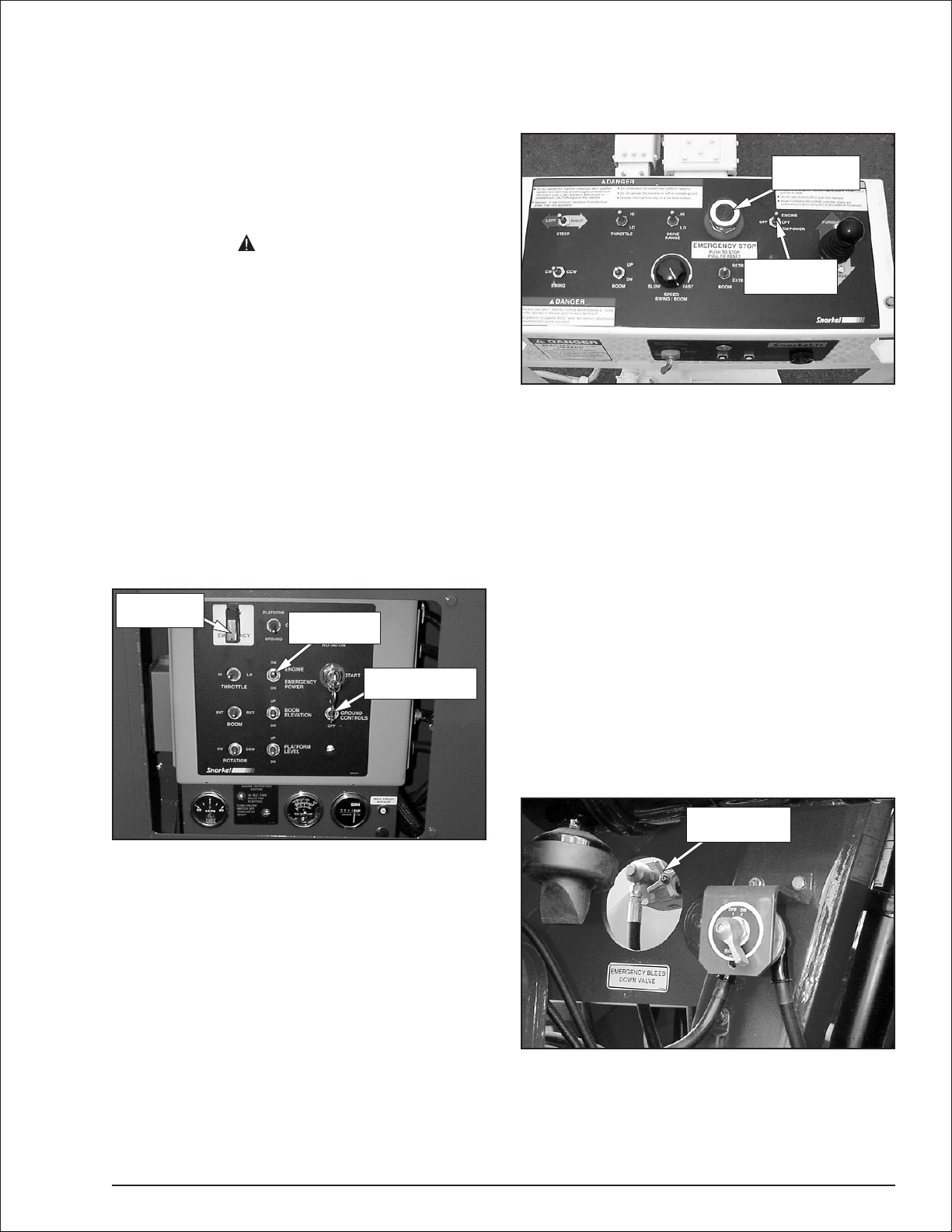
At the lower controls, the emergency stop is a
two-positiontoggleswitch with aredsafety guard (refer
to Figure 4.1). Push the guard down over the toggle
switchtodisconnect power toallcontrolcircuits.Lift the
guard and push the toggle switch up to restore power.
Emergency
Stop Switch
Emergency
Power Switch
Ground Controls
Switch
-
-
-
Figure 4.2—Upper Controls
Emergency
Stop Button
Emergency
Power Switch
Emergency Power System
-
The emergency power system includes a back-up
pump, motor, and battery. Use this system to operate
theboomand turntablefunctionsto lowertheplatform if
the main powersystemfails due to engineorpumpfailure.
Hold the emergency power switch (refer to Figure 4.1
and4.2) downtoactivatetheemergency powersystem.
The length of time the pump can be operated depends
on the capacity of the battery.
Emergency Lowering Knob
Theemergencyloweringknobmaybeusedtolowerthe
booms if the engine will not start and the emergency
powersystem willnot work.Theknobis onthe baseend
of the main boom lift cylinder and can be accessed
through the hole to the left of the battery disconnect
switch (refer to Figure 4.3).
Emergency
Lowering Knob
Figure 4.1—Lower Controls
Note
The lower controls override the upper controls. If the
upper control emergency stop button is engaged, the
lower controls can still be used to operate the aerial
platform.
At the upper controls, the emergency stop is a
two-position push button (refer to Figure 4.2).
Pushtheemergency stopbuttonin todisconnectpower
toall controlcircuits.Pullthebuttonouttorestorepower.
Figure 4.3—Emergency Lowering Knob
The knob may be turned to open the cylinder bleed
down valve for emergency lowering.
TB37 – 0172094 page 4 - 1
Page 16
Chapter 4. Safety Devices
Ground Controls Switch
The ground controls switch (refer to Figure 4.1) pre
vents boom and platform movement if a control switch
on the lower control panel is accidentally moved.
Holdtheswitchinthe controlson positiontooperate the
machine from the lower controls.
Platform Foot Switch
The platform foot switch (refer to Figure 4.4) prevents
boom and platform movement if a control on the upper
control panel is accidentally moved.
Top Rail
Lanyard Anchor
Platform
Foot Switch
T oeboar d
Gravity Gate
Figure 4.4—Platform
Step down on the platform foot switch to activate the
boom and platform controls.
Mid Rail
Guardrails
The guardrail system includes a top rail, mid rail, and
toeboardsaroundthesides of theplatform(refer toFig
ure 4.4).
Agravitygate oranoptionalswinginggateallowsforac
cesstotheplatform.The gatesclose automaticallyafter
entering or exiting the platform. The gate is part of the
guardrail system and must be securely fastened after
entering the platform.
Lanyard Anchors
Two lanyardanchorsforfallrestraintanchoragearepro
vided below the upper controls at the front of the plat
form (refer to Figure 4.4).
Note
The lanyard anchors are not for lifting or tying the
machine down.
All personnel in the platform must connect their fall re
straintdevicetoalanyardanchorbeforeraisingtheplat
form. Do not use the aerial platform for
arrest
-
anchorage.
Ground Fault Circuit Interrupter
The electrical power outlet (refer to Figure 4.5), at the
platform contains a ground fault circuit interrupter
(GFCI)to helppreventaccidental conductorgrounding.
Upper Control Panel
Electrical Power
Outlet
Figure 4.5—Electrical Power Outlet
Tilt Alarm
If the aerial platform chassis is out of level more than
fivedegrees whenthe mainboomisraisedorextended,
an alar m will sound.
DANGER
The aerialplatformcan tip over ifitbecomesunstable. Death or serious injury can result from a
tip-overaccident.Do notdriveor position the aerial
-
platform for elevated use near any drop-off, hole,
slope, soft or uneven ground,or other tip-over haz
ard.
Completely lower and retract the main boom and then
drive to a level surface when the tilt alarm sounds.
Thetiltalarm isforaddedprotection anddoesnotjustify
operating on anything other than firm, flat, level sur
faces.
-
Engine Protection Systems
-
A constant tone alarm will sound to warn against high
engine temperature or low oil pressure.
The engine will shut-down if the operatingtemperature
exceedsa preset levelor if theoilpressure is toolowfor
safe operation. An engine temperature gauge is below
-
the lower control panel (refer to Figure 4.6).
-
personal fall
-
-
page 4 - 2 TB37 – 0172094
Page 17
Chapter 4. Safety Devices
Drive Motion Alarm
An optional drive motion alarm may be provided on the
machine. When the drive/steer control is moved out of
neutral,thealarm sounds towarn personnelinthe work
area to stand clear.
Tem perature
Gauge
Figure 4.6—Engine Gauges
High Engine Temperature Alarm
If the coolant in a Ford engine exceeds 220°F (140°C)
an alar m will sound and the engine will shut off.
If the oil in a Deutz engine exceeds 230°F (110°C) an
alarm will sound and the engine will shut off. Any time
there is no alternator current being produced, an alar m
will sound and the engine will shut off. This prevents
high engine temperature if the fan belt breaks.
Donotrestarttheengine until theconditionthatcaused
the overheating has been corrected.
Low Oil Pressure Alarm
The low oil pressure alarm sounds when the engine oil
pressure is near the lower limit for safe engine operation. If the alarm sounds, lower the platform to the
ground and then turn the engine off. Do not restart the
engine until the condition that caused the low oil pres
sure has been corrected.
If the engine oil pressure falls below a safe operating
value the engine will shut off. The engine can be re
started with low oil pressure, but it will only run a few
seconds before it shuts off again.
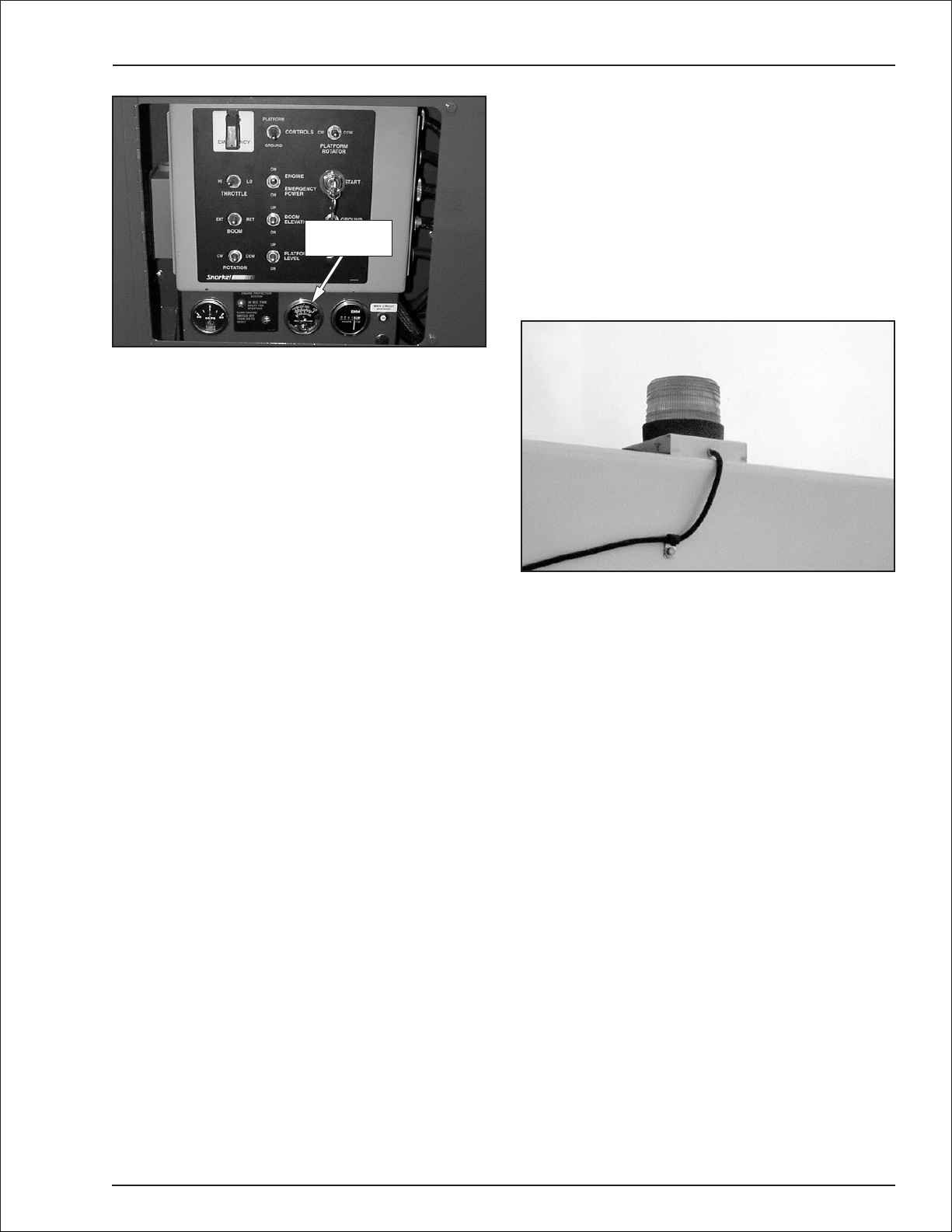
Flashing Light
An optional red or amber flashing light may be located
onthetop oftheboom (refertoFigure 4.7).The flashing
light warns personnel that the aerial platform is in the
area.
Figure 4.7—Flashing Light
The light flashes at about one flash per second when
the engine is running.
Driving Lights
Optional headlights and blinking tail lights may be installed on the machine. The headlights are located on
-
the top of the front cowling. The tail lights are mounted
on the sides of the rear cowling.
Drivinglightshelp improvevisibility whiledrivingthe ae
-
rial platformandhelp othersseeit too.Driving lightsare
not for driving on public roadways.
-
Horn
The optional horn may be used to warn personnel on
the ground. The horn is operational when the machine
is set up for operation from the upper controls.
TB37 – 0172094 page 4 - 3
Optional platformworklightsmaybe located on the top
railof theplatform, oneon eachside ofthe uppercontrol
panel.
Use the platform lights to improve visibility while work
ing aloft in dimly lit areas.Do not use theplatform work
lights to drive on public roadways.
Platform Work Lights
-
Page 18
Chapter 5. Gauges and Displays
The aerial platform is equipped with several gauges to
monitor the condition of the machine before and during
operation.
Hour Meter
The hour meter is located below the lower controls (re
fer to Figure 5.1).It measures the accumulated engine
operating time.
Tem perature Gauge
Ammeter Hour Meter
Figure 5.1—Lower Controls
Engine Temperature Gauge
The temperaturegaugeislocatedbelow the lower control panel (refer to Figure 5.1).
On liquid cooled engines it shows the temperature of
the water and antifreeze mixture in the engine block.
The gauge on air cooled engines shows the temperature of the engine oil as the oil leaves the filter.
Air Filter Gauge
-
Figure 5.2—Air Filter Gauge
Whentheareainsidethe clearsection oftheindicatoris
red, it’s time to change the filter element.
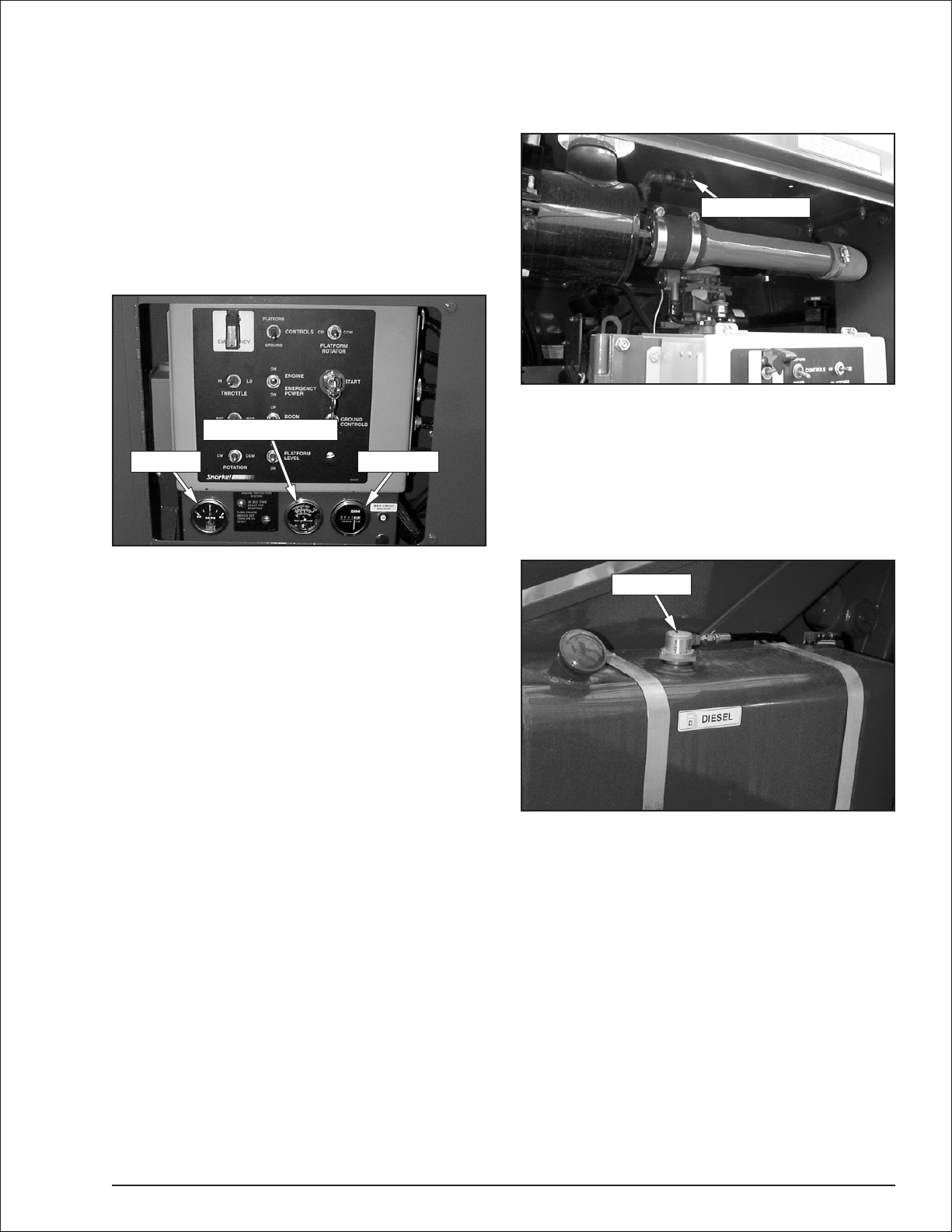
Fuel
Thefuelgauge islocatedon topofthe tank(refertoFig
ure 5.3). The gauge indicates the fluid level in fractions-of-a-full-tank.
Fuel Gauge
-
Ammeter
The ammeter is located below the lower control panel
(refer to Figure 5.1).The ammeter displays the level of
current flow from the alternator to the batteries.
Aftertheenginehas been running fora fewminutesun
dernormaloperatingconditions,theammetergaugein
dicator should read “0.”
-
-
Engine Air Filter Gauge
Theairfilter gauge (referto Figure 5.2)islocated above
the lower control panel on the air cleaner. The gauge
measures theairpressurebetweenthe intake manifold
and the air filter.
TB37 – 0172094 page 5 - 1
Figure 5.3—Gasoline or Diesel Fuel Tank
Note
Do not r un a diesel fuel tank empty. Air in the fuel line
makes the engine hard to start.
LPG tanks have a fuel gauge that has two scales.One
scalemeasuresthefuel levelwhenthe tank is mounted
vertical and theotherisusedwhenthe tank is mounted
horizontal (refer to Figure 5.4).
Page 19

Chapter 5. Gauges and Displays
Horizontal Scale
Figure 5.4—LPG Fuel Gauge
The LPG tank is mounted horizontally at the rear of the
turntable. Read the horizontal scale to determine the
fuel level.
Engine Oil
The engineoillevelismeasured with a dipstick(referto
Figure 5.5).Oil sump and filter capacities inthe engine
specificationchartsareapproximate.Thedipstickis the
only way to accurately determine the engine oil level.
The engine oil level should always be between the add
and full marks on the dipstick.
Dipstick
Hydraulic Fluid Filter Gauge
The fluid filter gauge (refer to Figure 5.6) is located on
thereturnlinefilteron top the reservoir.Thereservoiris
behind the door on the right side of the turntable.The
gauge indicates the condition of the filter. When the
needle on the gauge is in the red zone, it is time to
change the filter.
Filter Gauge
Figure 5.6—Fluid Filter Gauge
Fluid Level and
Temperature Gauge
A gauge on the end of the reservoir displays the level
and temperature of the hydraulic fluid (refer to Figure
5.7).
Figure 5.5—Engine Oil Dipstick
The dipstick is visible behind the lower control panel.
Level andTemperature Gauge
Figure 5.7—Hydraulic Reservoir
If the temperature rises above 200°F (93°C) stop ma
chine operation and let the fluid cool before resuming
operation.
-
page 5 - 2 TB37 – 0172094
Page 20

Chapter 6. Controls
Controlstoposition the platformarelocatedon the lower
control panel on the turntable and on the upper control
panel in the platform. Drive controls are located on the
upper control panel only.
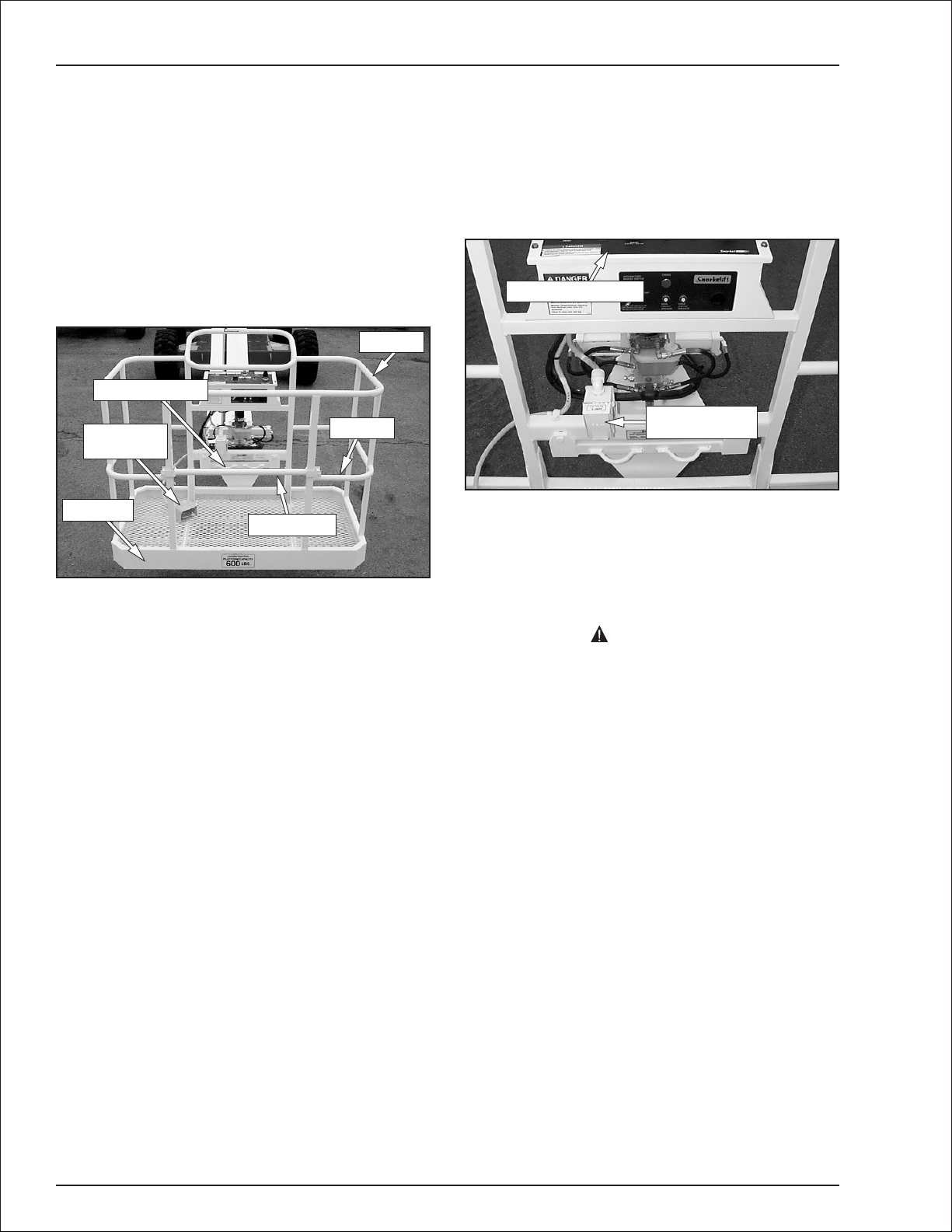
Battery Disconnect Switch
The battery disconnect is located behind the door on
the right side oftheturntableabove the battery (referto
Figure 6.1).
Figure 6.1—Battery Disconnect Switch
The battery disconnect removes electrical power from
all electrically controlled functionswhen in the off position. Place the switch in the on position to electr ically
connect the battery to the electrical system.
CAUTION
Only authorized personnel should operate the
aerial platform. Unqualified personnel may cause
injury to coworkers or property damage. Lock the
battery disconnect switchintheoffpositionbefore
leaving the aerial platform unattended.
Turn the batter y disconnect switch off to prevent unau
thorized use of the aerial platform.
●
Platform level switch
●
Platform rotator switch
●
Engine/emergency power switch
●
Throttle switch
●
Fuel switch
Figure 6.2—Lower Controls
Start Switch
The start switch works like an automobile ignition
switch. Hold it at start until the engine starts, then release it to on.If the engine dies, the key mustbeturned
to off before it will go back to start.
An alarm sounds when the switch is turned on to warn
others that the machine engine is being started.
Emergency Stop Switch
Theemergencystopisa two-positiontoggle switchwith
aredsafetyguard.Pushthered safetyguard downover
the toggle switch to disconnect power to all control cir
cuits.Lift theguardandpush the toggle switchupto the
on position to restore power.
-
Lower Controls
The lower controls (refer to Figure 6.2) are located on
the left side of the turntable. Boom and platform func
tions can be operated from the lower controls.The fol
lowing are located on the lower control panel.
●
Start switch
●
Emergency stop switch
●
Controls switch
●
Ground controls switch
●
Rotation switch
●
Boom elevation switch
●
Top boom switch
●
Boom switch
TB37 – 0172094 page 6 - 1
Controls Switch
Use the controls switch to select between lowercontrol
andupper controloperation.Place theswitchintheplat
formpositiontooperate the aerial platform fromtheup
percontrols andin thegroundpositionforlowercontrols
operation.
Ground Controls Switch
Hold the switch in the on position to operate the ma
chine from the lower controls.
This switch is spring returned to the off position.
-
-
-
Page 21

Chapter 6. Controls
Rotation Switch
The rotation switch is used to rotate the turntable in a
clockwise or counterclockwise direction. The switch is
spring returned to the center off position.
Hold the switchtotheright to rotate the turntable coun
terclockwise. Hold the switch to the left to rotate the
turntable clockwise.
Boom Elevation Switch
The boom elevation switchis used to raise or lower the
main boom. The switch is spring returned to the center
off position.
Hold the switch up to raise the main boom. Hold the
switch down to lower the main boom.
Boom Switch
The boom switch is used to extend or retract the tip
boom.The switchis springreturnedtothe centeroffpo
sition.
Hold the switch to the left to extend the tip boom.Hold
the switch to the right to retract the tip boom.
Place the switch in the low position fornormal machine
operationand inthe highposition forengineorhydraulic
system warm-up.
Fuel Switch
Engines on machines with the dual fuel option can be
operated using gasoline or liquefied petroleum gas
(LPG).Dual fuel machines haveagasolinetank behind
the door on the right side of the turntable and an LPG
tank at the rear of the turntable.
The fuel switch (refer to Figure 6.2) may be used to se
lect between gasoline and LPG operation.
Place the switchuptooperateon LPG and down to op
erate the engine using gasoline.
Circuit Breaker Reset Buttons
The lower control panel electrical system has a circuit
breakerfor themain, throttle,andrun circuits.Thereisa
reset button for each circuit breaker below the lower
control panel (refer to Figure 6.3).
-
-
Platform Level Switch
The platform level switch is used to level the platform
floor withrespecttotheground.Theswitch is spring returned to the center off position.
Hold the switch up to tilt the platform floor upward or
away from the ground. Hold the switch down to tilt the
platform floor downward or toward the ground.
Platform Rotator Switch
Theplatformrotatorswitchisused torotate theplatform
relative to the end of the tip boom. The switch is spring
returned to the center off position.
Hold the switch to the right to rotate the platform coun
terclockwise.Holdthe switchtothelefttorotate theplat
form clockwise.
Engine/Emergency Power Switch
Hold the emergency power switch down to operate ae
rial platform functions using the emergency power sys
tem. Release the switch to disengage the emergency
power system.
Note
The emergency power system is for lowering the
platform during an emergency and is not intended for
normal machine operation.
If the engine is running, it will stop when the switch is
placed in the emergency power position.
Main
Throttle
Run
Figure 6.3—Lower Control Gauge Panel
The upper control panel has a circuit breaker for the
-
main and drive circuits.The circuit breakers are on the
-
front of the upper control panel (refer to Figure 6.4).
-
-
Anti-Restart
Master Switch
Main Drive
Throttle Switch
Figure 6.4—Upper Control Panel Front
The throttle switch is used to set the engine throttle
speed to either low or high idle.
page 6 - 2 TB37 – 0172094
Page 22

Chapter 6. Controls
The circuit breakers protect the electrical wiring and
components from electrical overload in case of a short
circuit or other fault.
CAUTION
A tripped circuit breaker indicates a malfunction in
the electrical system. Component damage can re
sult ifthecause of the malfunctionisnot corrected.
Do not operate the aerial platform if the circuit
breaker trips repeatedly.
Push the button to reset the circuit breaker.
Upper Controls
The upper controls (refer to Figure 6.5) are located on
the control panel at the platform. Boom, platform, and
drivefunctions canbeoperatedfrom theuppercontrols.
The following controls are located on the upper control
panel.
●
Anti-restart master switch
●
Emergency stop button
●
Speed knob
●
Swing switch
●
Boom up/down switch
●
Boom extend/retract switch
●
Level switch
●
Steer switch
●
Drive joystick
●
Drive range switch
●
Engine/emergency power switch
●
Throttle switch
●
Platform rotator switch
This switch is similar to an automobile ignition switch.
Turn the switch to start until the engine starts, then re
lease it to on. If the engine dies, the switch must be
turned to off before it can be turned back to start.
An alarm sounds when the switch is turned on to warn
others that the machine engine is being started.
-
Note
Onsomemachines itmaybe necessary topauseabout
threesecondsinthe on positionbeforegoing to start so
the starter can engage.
Turnthe switchtooff to turn theengineoff and savefuel
iftheplatform is tostay inaparticularpositionfor a long
time.
Emergency Stop Button
The emergency stop is a two-position, red push button
onthetopof the upper control panel.Push the buttonin
to disconnect power to all control circuits at the upper
controls.Pull the button out to restore power.
Note
The lower controls override the upper controls. If the
upper control emergency stop button is engaged the
lower controls can still be used to operate the aerial
platform.
Pushtheemergencystopbuttoninwhentheuppercontrolsarenotinuse toprotectagainstunintentionaloperation.
Speed Knob
Use the boom speed control knob to control the speed
of the following boom functions.
●
Turntable swing clockwise/counterclockwise
●
Main boom raise/lower
Set the knob to slow when beginning a boom move
ment. The speed may be increased by slowly rotating
the knob toward fast. For smooth operation, rotate the
knob to slow when ending boom movement.
-
-
Swing Switch
The swing switch is used to rotate the turntable in a
clockwise or counterclockwise direction. The switch is
spring returned to the center off position.
Hold the switchtotheright to rotate the turntable coun
terclockwise. Hold the switch to the left to rotate the
turntable clockwise.
Figure 6.5—Upper Control Panel
Anti-Restart Master Switch
The machine engine can be started from the platform
using the anti-restart master switch on thefrontoftheup
per control panel (refer to Figure 6.4).
TB37 – 0172094 page 6 - 3
Boom Up/Down Switch
The boom up/down switchis used to raiseor lower the
main boom. The switch is spring returned to the center
off position.
Hold the switch up to raise the main boom. Hold the
switch down to lower the main boom.
-
Page 23

Chapter 6. Controls
Boom Extend/Retract Switch
The boom extend/retractswitch is used to extendorre
tract the tip boom. The switch is spring returned to the
center off position.
Hold the switch down to extend the tip boom. Hold the
switch up to retract the tip boom.
Level Switch
Thelevelswitchis usedtoleveltheplatform floorwithre
spect to the ground. The switch is spring returned to the
center off position.
Hold theswitchup to tilt theplatformfloorupward or awa y
from the ground.Hold the switch down to tilt the platform
floor downward or toward the ground.
Steer Switch
The steer switch is used to steer right and left. The
switch is spring returned to the center off position.The
steering and drive functions may be operated simulta
neously.
Note
The steering wheels are not self-centering. Set the
steeringwheelsstraightaheadaftercompleting aturn.
Hold the switchtothe right to turnrightandtotheleft to
turn left as indicated by the directional arrows on the
chassis.
powersystem.Place theswitchintheoff positiontodis
engage the emergency power system.
-
Note
The emergency power system is for lowering the
platform during an emergency and is not intended for
normal machine operation.
If the engine is running, it will stop when the switch is
placed in the emergency power position.
-
Throttle Switch
The throttle switch is used to set the engine throttle
speed to either low or high idle.
Place the switch in the low position fornormal machine
operation and in high to drive at maximum speed.
Platform Rotator Switch
The platform rotator switch (refer to Figure 6.6)is used
to rotatetheplatform relative totheendofthe tip boom.
Theswitchisspringreturnedto thecenteroffposition.
-
-
Drive Joystick
Thedrivejoystickisusedto controlforwardandreverse
motion of the aerial platform.
Holdthejoystickforwardtomovetheaerialplatform for
ward and backward to move in reverse as indicated by
the directional arrows on the chassis.
Drive Range Switch
The driverangeswitch has twopositionstoselectdrive
wheel operation:
●
HI—high speed and low torque operation.
●
LO—low speed and high torque operation.
Engine/Emergency Power Switch
Place the switch in the engine position for aerial plat
form engine operation.
Placetheswitchinthe emergencypowerposition toop
erate aerial platform functions using the emergency
-
Figure 6.6—Upper Control Panel Side
Hold the switch to the right to rotate the platform coun
terclockwise.Holdthe switchtothelefttorotate theplat
form clockwise.
Horn Button
Theoptionalhorn buttonison therightside oftheupper
control panel. Press the button to sound the horn.
Platform Foot Switch
-
The upper controls are interlocked through the platform
footswitch(refertoFigure6.7).Step downon andholdthe
platform foot switch to activate the drive and boom func
tions from the upper controls.
-
-
-
page 6 - 4 TB37 – 0172094
Page 24

Platform
Foot Switch
Figure 6.7—Platform
Machine/Generator Switch
The switch for the optional generator is located on the
upper front of the control panel (refer to Figure 6.8).
Chapter 6. Controls
Machine functions willnotoperatewhiletheswitch is in
the generator position.
Dual Fuel
Engines on machines with the dual fuel option can be
operated using gasoline or liquefied petroleum gas
(LPG).Dual fuel machineshave agasolineandan LPG
tank on the left side of the chassis.
The switch to select between gasoline and LPG opera
tion is on the lower control panel (refer to Figure 6.9).
-
Machine/Generator Switch
Figure 6.8—Upper Control Panel Front
Withtheengine running, placetheswitchinthe genera
tor position to provide electrical power to the electrical
outlet at the platform.
Dual Fuel
Switch
Figure 6.9—Lower Controls
Place the switchuptooperateon LPG and down to operate the engine using gasoline.
Driving and Platform Work Lights
The control for the optional driving lights is on the back
ofeachlight.Placetheswitch intheonposition to operate the driving lights.
Thecontrolfortheoptionalplatformwork lightsison the
-
back of each light.
TB37 – 0172094 page 6 - 5
Page 25

Chapter 7. Prestar t Inspection
Potentialservice and safetyproblemsmay be detected
byinspectingtheaerialplatform. This chapter includes
information on properly inspecting the aerial platform
and includes a prestart inspection checklist at the end
of the chapter to ensure that no areas are overlooked.
DANGER
The potential for an accident increases when oper
atinganaerial platformthat is damagedor malfunc
tioning. Death or serious injury can result from
suchaccidents.Donot operate theaerial platformif
it is damaged or malfunctioning.
Perform a prestart inspection at the beginning of each
shift, beforeusingtheaerialplatform on the job.The in
spection site must have a smooth and level surface.
Operator’s Manual
The manual holder is located in the engine compart
ment(refertoFigure7.2)on theleftsideofthe machine.
Make cer tain it is securely fastened in place.
Coolant
Fordenginesareliquid cooled.Whenthe engineis cold,
there should be about 1″(2.5 cm) of coolant in thebot
tom of the reservoir (refer to Figure 7.2).
CAUTION
Enginecoolantescaping underpressure cancause
-
serious burns.Shut theengine off and letitcool be
-
fore removing the radiator cap.
Add coolant, if necessary, when the engine is cold and
notrunning.Whenrunning atoperatingtemperaturethe
coolant should be at the Hot level.
Deutzenginesare air cooled.Visually inspecttheairin
-
takeand fan(refertoFigure 7.3)tobe suretheyare free
of obstructions thatcouldstopor slow the flowofair.In
spect the fan belt to see that it is in place and not
cracked.
-
Fan
-
-
-
-
Coolant
Reservoir
Figure 7.2—Operator’s Manual Holder
Checkto see thattheproper Operator’sManualis inthe
holder.The manual should be complete with all pages
intact and in readable condition.
Manual Holder
Engine
Open the engine compartment doors on both sides of
the machine and visually inspect the engine and its
components with the engine off.
Oil Level
Check the engine oil level before starting the engine so
the oilhasdrainedtothe pan. Theproperoillevel isbe
tween the add and full marks on the dipstick.
The distance between the top and bottom dipstick
marks corresponds toabout 1 quar t US (1 l). Add oil, if
necessary, before starting the engine.
Fan Belt
Figure 7.3—Deutz Air Intake
Radiator
Inspect the radiator hoses and clamps for wear, leak
age, or damage (refer to Figure 7.4). Make sure the
hoses are not hardened, cracked, or feelspongy. Make
sure the cap is in place and tight.
Hose
-
Figure 7.4—Radiator
-
Cover
Cap
TB37 – 0172094 page 7 - 1
Page 26

Chapter 7. Prestar t Inspection
Coolant leaks are easily visible on the ground. Check
under the chassis for coolant that has leaked.
Makesure theradiatorcoreandventilationopeningson
the cover are free of bugs, dirt, or foreign material that
might restrict airflow.
Fuel Tank
Check the fuel level (refer to Figure 7.5)and add fuel if
necessary. Make sure the cap is securely fastened on
gasoline or diesel tanks.
Cap
Fuel Line
Fuel Gauge
Fuel Line
Fuel Gauge
7. Connect the fuel line and open the shutoff valve.
Fuel Line
Visuallyinspecttheentire length ofthefuel line.Startat
thefueltankandtrace theline (referto Figure7.5)tothe
engine inspecting for leaks and damage.
Air Filter
Theairfiltergauge (refer toFigure7.7)has an indicator
to show when the filter needs replaced.
Air Filter Gauge
Figure 7.5—Gasoline or Diesel Tank
Use the following procedure to change the LPG tank.
1. Close the shutoff valve (refer to Figure 7.6).
Shutoff Valve
Latch
Quick Disconnect
Fitting
Slot
Pin
Figure 7.6—LPG Tank
2. Remove the fuel line from the tank using the quick
disconnect fitting.
3. Pulluponeachlatchtoreleasethestraps from the
tank.
4. Carefully lift the tank from the cradle.
5. Placea fulltankin thecradlemakingsurethe slotin
the tank aligns with the pin.
6. Latch both straps to secure the tank.
Figure 7.7—Air Filter
To inspect the air filter:
1. Turn thebatterydisconnectswitch onandclose the
cowling door.
2. On dual fuel machines, set the fuel switchtoeither
LPG or gasoline.
3. At the lower controls, place the emergency stop
switch in the on position.
4. Insert the key into the master switch and turn the
engine on.
5. Checktheclearzoneafter runningtheenginefor30
seconds.
●
If the indicator is red, replace the filter.
●
If the indicator is clear, the filter is OK.
6. Shut off the engine.
Charging System
When the engine is running, the ammeter needle (refer
to Figure 7.8) should be to the right of “0.” Left of the “0”
is discharging.
page 7 - 2 TB37 – 0172094
Page 27

Chapter 7. Prestar t Inspection
Ammeter
Tem perature Gauge
Figure 7.8—Ammeter
Hour Meter
Cold Weather Start Kit—Block Heater
Ifthemachineisequipped withan optionalengineblock
heater, visually inspect the heater and power cord. In
spectforleaks around theheaterand fordamagetothe
power cord.
Electrical System
Electrical powerissupplied from either oneortwo, 335
amp, 12 volt batteries. These batteries supply 12 volt
DC electrical power to operate the aerial platform electrical and electrohydraulic components.
Machines with gasoline engines have one battery and
machines with diesel engines have two batteries.
DANGER
Batteries give off hydrogen and oxygen that can
combineexplosively.Deathor seriousinjury canre
sult from a chemical explosion. Do not smoke or
permit open flames or sparks when checking the
batteries.
CAUTION
Even with low voltage electrical systems, severe
arcing can occur. Electrical shock or component
damage can result from contact with energized
conductors. Use caution when working with any
electrical device.
Thebatteriesarebehindthe dooron therightsideofthe
turntable.
Caps
Terminals
Figure 7.9—Emergency Power Battery
Include the emergency power battery when inspecting
and servicing the electrical system.
-
Battery Fluid Level
Remove the caps from each batter y (refer to Figure
7.9).Visually check the battery fluid level. If the level is
not within
side each hole,add distilled water.
Replace the caps on the batteries.The caps must be in
place and tight during machine operation.
1
/4″ (6 mm) of the bottom of the filler neck in
Battery Terminals
Check the top of the batteries, the terminals,andcable
ends(refertoFigure7.9).Theyshouldbecleanandfree
of corrosion and dirt. Clean the top of the batteries if
necessary. Clean the terminals and cable ends with a
wirebrushor terminal cleaningtool.Allcable endsmust
-
be securely fastened to the terminals.
Cables and Wiring Harness
Inspect all cables and wiring for wear and/or physical
damage such as loose connections, broken wires, and
frayed insulation. Check the wiring in areas where a
change in routing direction maycausethemtobecome
pinched(refertoFigure7.10).Makesurethecablesand
wires are properly routed to avoid sharp edges, pinch
ing, and scuffing.
-
-
Emergency Power Battery
Theemergency powerbattery (refertoFigure7.9)isbe
hind the door on the right side of the chassis. The bat
tery is automatically charged when the engine is
running.
TB37 – 0172094 page 7 - 3
-
-
Page 28

Chapter 7. Prestar t Inspection
Figure 7.10—Cables and Wiring Harness
Hydraulic System
Hydraulic powerissuppliedfrom an engine dr iven vari
able displacement piston pump.
CAUTION
Not all hydraulic fluid is suitable to use in the hy
draulicsystem.Somehave poorlubricating charac
teristics and can increase component wear. Only
use hydraulic fluid as recommended.
If necessary, remove the filler cap and add fluid of the
proper type.Referto Chapter 2 for the proper type and
gradeof hydraulicfluidtouse.Theneedtoregularlyadd
fluid indicates a leak that should be corrected.
The sight glass on the reservoir has an internal ther
mometertomeasurethefluid temperature.Thetemper
ature should be less than 200°F (93°C).
Fluid Filter
Checkingtheconditionof the hydraulicfluidfilter is par t
of the machine maintenance schedule and should not
be performed by the operator.
-
-
-
-
DANGER
Hydraulic fluid escaping under pressure can have
enough force to inject fluid into the flesh. Serious
infection orreactioncan result if medical treatment
is notgivenimmediately.In caseofinjuryby escapinghydraulic fluid,seekmedical attentionat once.
The hydraulic reservoir is behind the door on the left
side of the turntable.The pump is mounted on the engine.
Fluid Level
Check the hydraulic reservoir fluid level with the aerial
platform stowed on a level surface.Thefluid levelmust
be between the full and add marks as viewed on the
sight glass (refer to Figure 7.11).
Full
Add
Figure 7.11—Fluid Level Indicator
Hoses, Tubes, and Fittings
Inspect all hydraulic hoses, tubes, and fittings for wear,
leakage, or damage (refer to Figure 7.12). Make sure
the hoses are properly routed to avoid sharp edges,
kinking, and scuffing. Inspect the tubes for dents or
other damage that may restrict fluid flow.Makesure all
hoses and tubes are held firmly in their support brackets.
Figure 7.12—Hose, Tubes, and Fittings
Hydraulic fluid leaks are easily visible on the ground.
Check under the chassis for fluid that has leaked.
Tires and Wheels
Visually inspect the tires and wheels (refer to Figure
7.13) to make sure theyare suitable for service.Check
the wheel lug nuts to see that none are missing, dam
aged, or loose.
-
page 7 - 4 TB37 – 0172094
Page 29

Chapter 7. Prestar t Inspection
Emergency
Stop Switch
Emergency
Power Switch
Ground Controls
Switch
Figure 7.13—Tires and Wheels
The aerial platform may have air or foam filled tires.Air
filled tires have a tire pressure decal near the valve
stem.The valvestem also hasavalve corelikean auto
mobile tire.Foam filled tires do not have a pressure de
cal oravalvecore.Differenttypesof tires havedifferent
inspection requirements.
Air Filled
Checkairfilledtires verycarefullyfor wear,cuts, punctures, or imbedded objects.
DANGER
The aerialplatformcan tip over ifitbecomesunstable. Death or serious injury can result from a
tip-overaccident. Donotoperate theaerialplatform
if a tire is leaking air or is in poor condition where a
blow out could occur.
Test the air pressure with a pressure gauge to make
sure the tires are proper ly inflated.Check the tires sev
eral times throughout the daytoseethattheyareprop
erly inflated.
Foam Filled
Inspectforlargeholes or cutswherefoamiscoming out
ofthetire.Lookforlarge imbedded objects,suchas an
gle iron, that can rip a tire open.
Punctures caused by bolts, screws, or nails are not a
problem for foam filled tires.
Lower Control Station
With no personnel in the platform, test theoperation of
each control from the lower controls (refer to Figure
7.14).
Figure 7.14—Lower Controls
Operating Controls
-
Use the following procedure to operate the machine
-
from the lower controls.
1. Turn the battery disconnect switch on.
2. Atthelower controls,lifttheemergencystop safety
guard up, and push the toggle switch up to the on
position.
3. Insert the key into the master switch and turn the
switch to start until the engine starts, then release
it.
4. Let the engine warm to operating temperature.
5. Hold the ground controls switch in the on position.
DANGER
Pinch points may exist between moving components. Death or serious injury can result from be
coming trapped between components, buildings,
-
structures, or other obstacles. Make sure all per
-
sonnel stand clear of the aerial platform while per
forming the prestart inspection.
6. Test the operation of each function in both direc
tions.
-
Note
When checking the turntable rotation function in the
clockwisedirection,thetur ntablewillrotatetowardyou.
Emergency Stop
Push the emergency stop safety guard down to turn off
theengine.Thelower controlfunctionsshould notoper
ate with the emergency stop in this position.
Emergency Power
Place the battery disconnect switch, the emergency
stop switch, and the master switch in the on position.
Hold the engine/emergency power switch in the emer
gency powerposition and the ground controls switchin
the on position to operate the aerial platform from the
lower controls using the emergency power system.
-
-
-
-
-
-
TB37 – 0172094 page 7 - 5
Page 30

Chapter 7. Prestar t Inspection
Emergency Lowering
The main boom can be loweredinanemergencyusing
theemergencyloweringknob.Theemergencylowering
knob is at the base of the main boom lift cylinder.
Use the followingprocedure to test the emergency low
ering system.
1. Use the lower controls to raise the main boom
boom until the emergency lower knob is visible in
the access hole as shown in Figure 7.15.
Emergency
Lowering Knob
Main Boom
-
Switch Arm
Figure 7.16—Boom Switch
4. Openthe door ontheleft side oftheturntableto ac
cess the level sensor (refer to Figure 7.17).
-
Figure 7.15—Emergency Lowering Knob
2. Turn the engine off.
DANGER
Pinch points may exist between moving components. Death or serious injury can result from becoming trapped between components. Stand clear
ofmovingcomponents whiletestoperating the machine.
3. Slowlyturn the knob to open the bleed down valve.
The boom should slowly lower by gravity.
DANGER
Thepotentialfor anaccidentincreases whensafety
devices do not function properly. Death or serious
injury can result from such accidents. Fully close
the emergency lowering knob before operating the
aerial platform.
4. Turn the knob to close the cylinder bleed down
valve.
Level Sensor
Use the following procedure to test the level sensor.
1. Position the aerial platform on a smooth, flat, level
surface.
2. Remove all persons and materials from the plat
form.
3.
Start theengine and raise the main boom about 8′
(2.4 m) so the boom switch arm on the right side of
the turntable no longer contacts the boom (refer to
Figure 7.16).
Level Sensor
Figure 7.17—Level Sensor
5. Pullthe levelsensorto thesideas faraspossible to
activate the tilt alarm.
DANGER
Thepotentialfor anaccidentincreases whensafety
devices do not function properly. Death or serious
injury can result from such accidents. Do not alter,
disable, or override any safety device.
6. If the alarm does not sound, remove the machine
from service until the problem is corrected.
7. Lower the main boom.
Flashing Light
If the machine is equipped with an optional flashing
light, visually check to see that it flashes. The light
should flash when the engine is r unning.
Sandblast Protection Kit
The optional sandblast protection kit protects the cylin
ders from abrasion while sandblasting or from paint
overspray.Rubbercoversprotect eachcylinderrod as it
extends and retracts. The covers prevent sand and
paint from damaging the cylinder seals and rod.
-
page 7 - 6 TB37 – 0172094
Page 31

Chapter 7. Prestar t Inspection
Inspect the covers while operating the machine to en
sure they are securely fastened and completely cover
the cylinder rod. Make sure there are no holes in the
covers.
Structures
Visuallyinspectallweldmentsand relatedcomponents.
It is important to inspect the fasteners that connect the
components.
Weldments
Visuallyinspectallweldments forabnormalwear,abra
sion, or deformation that could cause interference be
tween moving parts.
Inspect the welds on the structural components. Pay
particular attention to boom welds. The area to be in
spected should be clean and free of dirt and grease.
Lookforvisiblecracksin theweldand atthe weldtopar
ent material joint.A bright light may be used to provide
adequate visibility of the inspection area.
Slide Pads
Themainboom hasslidepads (referto Figure7.18)between the main and tip boom sections.
Raise the main boom to access the rotation bearing
bolts in the turntable (refer to Figure 7.19).
Rotation BearingBolts
-
-
Inspect the rotation bearing bolts to ensure that none
-
are missing, damaged, or loose.
Figure 7.19—Rotation Bearing Bolts
Upper Control Station
Inspect the platform and upper controls only if all func
tions operated properly from the lower controls.
Guardrail System
The guardrailsystem(refer toFigure7.20)includesthe
toprail,midrail,toeboardsandagravitygate oroptional
swinging gate.
-
Slide Pads
Figure 7.18—Slide Pads
Use the lower controls to raisethemain boom about 6′
(1.8 m). Extend the tip boom about 1′ (30 cm).Visually
inspect the slide pads to make sure they are in place
and are not obviously loose.
Inspect the surface where the pads contact the inter
mediate and tip booms.The paint must be in place with
no signs of bare metal.
Fasteners
Visually inspect allfastenersto see that none are miss
ing or loose.
Pay par ticular attentionto all of the bolts, nuts, rollpins,
collars,andsnapringsthatconnect the booms and cyl
inders.They should all be present, tight, and not dam
aged in any way.
Lanyard Anchor
Platform
Foot Switch
T oeboar d
Figure 7.20—Guardrail System
Inspect all components of the guardrail system. The
-
rails and toeboards must all be in placeand free of any
damage or deformation. Visually check the rail and
toeboard welds for cracks. All bolts and nuts fastening
the platforminplacemust be present andnotshowany
signs of looseness.
-
Inspect the gravity gate to be sure it is present, is not
damaged, and moves freely.
Inspect the optional swinging gate tosee that it swings
-
freely, closes firmly, and is not deformed in any way.
-
Makesure thespringcloses andsecuresthe gatewhen
the gate is closed.
Gravity Gate
Mid Rail
Top Rail
TB37 – 0172094 page 7 - 7
Page 32

Chapter 7. Prestar t Inspection
Lanyard Anchors
There are two lanyard anchors below the upper control
panel (refer to Figure 7.20).
Visually inspect the lanyard anchors to makesurethey
are in place, are not deformed and are securely fas
tened to the platform.
Operating Controls
Use the following procedure to operate the machine
from the upper controls.
1. Turn the battery disconnect switch on.
2. At the lower controls, place the emergency stop
switch and the master switch in the on position.
Place the control switch in the platform position.
3. Attheuppercontrols (refertoFigure7.21),pullthe
emergency stop button out.
Emergency
Stop Button
8. Thedrive rangeswitchandmaximumtravelspeeds
are interlocked through a limit switchon the turnta
ble that senses the main boom position.When the
main boom is raised approximately 8′ (2.4 m) the
machineshouldtravelinlow speedonly.Tooperate
-
in high speed the booms must be stowed.
Emergency Stop
Push the emergency stop button in to turn off the en
gine. The upper control functions should not operate
with the emergency stop in this position.
Emergency Power
Pull the emergency stop button up and place the
anti-restart master switch in the on position.
Hold the engine/emergency power switch in the emer
gency power position and step on the platform foot
switchtooperatetheaerialplatform fromthe uppercon
trols using the emergency power system.
Horn
Press the horn button to ensure that it sounds to warn
personnel in the area.
-
-
-
-
Figure 7.21—Upper Controls
4. Turn the anti-restart master switch to start until the
engine starts, then release it.
5. Let the engine warm to operating temperature.
DANGER
Pinch points may exist between moving compo
nents. Death or serious injury can result from be
coming trapped between components, buildings,
structures, or other obstacles. Make sure all per
sonnel stand clear of the aerial platform while per
forming the prestart inspection.
6. Test the platform foot switch by moving a boom
function switch without stepping on the foot switch.
If movement occurs the interlock is not functioning
properly.Do notoperatethe machineuntilthe prob
lem is corrected.
7. Test theoperationof each control inbothdirections
from the upper controls.
Electrical Power Outlet
Connect a source of 125 volt AC power to the
power-inputconnectorontheleftsideofthe lowercontrol panel (refer to Figure 7.22).
Power-Input
Connector
-
-
-
-
Some machines may have an electrical outlet at the
platform, but no power-input connector. In that case,
powerissuppliedbyanoptionalACgenerator.Anexter
nal power source is not required.
With the engine running, place the machine/generator
control(referto Figure 7.23)inthe generator positionto
provide electrical power to the two electrical outlets at
theplatform andto theoutlet onthe endof thegenerator
housing.
Figure 7.22—Power-Input Connector
-
page 7 - 8 TB37 – 0172094
Page 33

Machine/Generator Switch
Figure 7.23—Upper Control Panel Front
Pluganelectrical tool intothereceptacle attheplatform
and at thegeneratorandtrytooperatethetoolto verify
proper operation of the outlet.
The outlet is equipped with a ground fault circuit inter
rupter (GFCI). Use the following procedure to test the
GFCI.
1. Push the black test button (refer to Figure 7.24).
Chapter 7. Prestar t Inspection
Drive Motion Alarm
The machine may be equipped with an optional drive
motion alarm. Drive in both the forward and reverse di
rections to ensure that the alarm sounds to war n per
sonnel in the area that the aer ial platform is in motion.
Driving and Work Lights
Themachine maybeequippedwith drivinglightsand/or
platform working lights.Turn the engine on and use the
switchon thebackofeachlight tomomentarilyturnit on
to see that it works.
Platform Control Cover
The machine may be equipped with an optional plat
form control cover. Inspect the cover to ensure it fits
properly over the control panel.
Tow Kit
The machine may be equipped with an optional tow kit.
Inspect the tow bar and steering arm to verify the com
ponents are present and in working condition.
-
-
-
-
Reset Button
Figure 7.24—Electrical Power Outlet
2. Plug an electrical tool into the outlet and verify the
power is off.
●
If the power was off, push the reset button to
restore power.
●
If the power was on, repair or replace the
receptacle.
Test Button
Placards and Decals
Inspect all safety and operational placards and decals.
Make certain they are in place, in good condition, and
are legible.
Theplacardsand decalsmaybe cleanedwithsoap and
water,and asoftcloth if thewordsor pictures cannotbe
seen.
CAUTION
Solvents may contain hazardous ingredients. Fol
lowthemanufacturer’slabel forproperuse anddis
posal. Wear protective gloves and splash-proof
safety glasses when using solvents.
Wet paint overspray may be removed using a natural
biodegradable solvent and a soft cloth.
Replace any missing or illegible placardsor decals be
foreoperatingtheaerial platform.Placardand decalkits
are available from Snorkel dealers.
The safety related placards and decals are illustrated
on the following pages.
-
-
-
TB37 – 0172094 page 7 - 9
Page 34

Chapter 7. Prestar t Inspection
0074311
(One per Cylinder)
0074311
0323896
Right Side
0323896
0323896
0070901
0323897
0070901
Lower Control Door
0323897
page 7 - 10 TB37 – 0172094
Page 35

0074316
(Gasoline Engines Only)
0081441
(Dual Fuel Engines Only)
Chapter 7. Prestar t Inspection
0074316
0074210
Lower Control Door (Open)
0074210
Rear of Turntable
0081441
(LPG Engines Only)
0323896
Right Side of Turntable
Rear View
0082203
(Tow Option Only)
0081441
0082203
0323896
0151410
(Gasoline Engines Only)
0151410
TopViewofRadiator
TB37 – 0172094 page 7 - 11
Page 36

Chapter 7. Prestar t Inspection
0323899
0323899
0323896
0082160
(Tow Option Only)
0072531
Left Side
0082160
0323896
0082164
(Tow Option Only)
0072531
0082164
Platform
0170311
0323899
0170311
Upper Control Panel
0323899
page 7 - 12 TB37 – 0172094
Page 37

Chapter 7. Prestar t Inspection
Prestart Inspection Check List
Item Inspect for Ok
Operator’s manual
Engine
Oil level
Coolant
Radiator
Fuel tank and line
Air filter
Charging system
Cold weather start kit
Electrical system
Emergency power battery
Battery fluid level and terminals
Cables and wiring harness
Hydraulic system
Fluid level
Fluid filter
Hoses, tubes, and fittings
Cold weather warm-up kit
Tires and wheels
Air filled
Foam filled
In manual holder
Between full and add marks
Liquid cooled engines-proper fluid level
Air cooled engines-air intake and fan free of
obstructions/belt in good condition
Cap tight, good condition and clean
Tank full, cap in place and tight/no leaks
Green indicator
Proper operation
No damage or deformation
Condition and charged for proper operation
Proper level/clean, connectors tight
No wear or physical damage
Between full and add marks
Verify operation in the green zone
No leaks
Proper operation
Good condition, proper inflation
Good condition
Lower control station
Operating controls
Emergency stop and emergency power
Emergency lowering
Level sensor
Flashing light
Sandblast protection kit
Structures
Weldments
Slide pads
Fasteners
Upper control station
Guardrail system and lanyard anchors
Operating controls
Emergency stop and emergency power
Horn
Electrical power outlet
Drive motion alarm
Driving and work lights
Platform control cover
Tow kit
Proper operation
Shuts off lower controls/proper operation
Proper operation
Sounds tilt alarm
Proper operation
In place and proper operation
Welds intact, no damage or deformation
In place, no damage or deformation
In place and tight
No damage or deformation
Proper operation
Shuts off upper controls/proper operation
Sounds when activated
Proper operation
Sounds when aerial platform moves
Proper operation
In place and proper operation
In place, no damage or deformation
Placards and decals
TB37 – 0172094 page 7 - 13
In place and readable
Page 38

Chapter 8. Operation
The aerial platform may be operated from either the
lower or upper controls.
DANGER
The aerial platform is not electrically insulated.
Deathor seriousinjurycan resultfromcontactwith,
or inadequate clearance from, an energized con
ductor.Do not go closer than the minimumsafeap
proach distance as defined by ANSI.
Pinch points may exist between moving compo
nents. Death or serious injury can result from be
coming trapped between components, buildings,
structures, or other obstacles. Make sure there is
sufficient clearance around the machine before
moving thechassis,booms, or platform.Allow suffi
cient roomandtimetostop movement to avoidcon
tact with structures or other hazards.
The aerialplatformcan tip over ifitbecomesunsta
ble. Death or serious injury can result from a
tip-over accident. Operate the aerial platform on a
firm, flat, level surface. Avoid travel speeds and/or
rough terrain that could cause sudden changes in
platform position.
The platform rated work load is the total weight of the
personnel and equipment thatmaybe lifted in the platform. The work loads are stated on the platform rating
placardmountedon thetoeboardatthefront oftheplatform.
DANGER
The aerialplatformcan tip over ifitbecomesunsta
ble. Death or serious injury can result from a
tip-over accident. Do not exceed the capacity val
ues indicated on the platform rating placard.
Capacity values indicate the rated lifting capacity and
do not indicate aerial platform stability.
The operator bears ultimate responsibility for ensuring
thattheaerialplatform is properly setupfor theparticu
lar conditions encountered.
Cold Weather Start-Up
If the ambient temperature is 32°F (0°C) or below, the
engineand hydraulicsystemoilmayneedtobewarmed
before operation. Do not operate the engine at more
thanafastidleuntil theengineand hydraulicoil hashad
achanceto warm.The enginemaybeequipped withan
optional cold weather start kit.
Cold, thick hydraulic oil does not flow well and may
cause delay in response to control movement and low
voltage output of the AC generator. Cold hydraulic oil
may also cause cavitation and pump damage. The hy
draulic system may be equipped with an optional cold
weather warm-up kit.
Engine Cold Weather Start Kit
Theoptionalenginecoldweatherstartkitmaybe anen
gine blockheater or a manifoldair pre-heater.The type
of starting assist system depends on the engine manu
facturer.
Thelast twolettersofthemodelnumberstampedonthe
-
serial number placard indicates the engine manufac
-
turer (refer to Figure 8.1).The serial number placard is
mounted on the front of the turntable.
-
Last Two Letters
-
of Model Number
FO Ford Engine block heater
DZ Deutz Manifold air
-
-
-
-
-
-
Figure 8.1—Engine Manufacturer/Start System
Refer to the engine manufacturer below f or specific cold
weather start-up information for that particular engine
type and cold weather start system.
Ford—Block Heater
Plugtheheater cordintoa 125 VoltAC,600watt source
eight hours before starting the engine. The heater will
warm the engine block to make cold weather starting
easier.
Unplug the power cord before starting the engine.
Deutz—Manifold Preheater
Atthelowercontrols,hold themanifold heaterswitchon
for about a minute before turning the master switch to
start the engine. A glow plug in the manifold preheats
the air to help start the engine. Continue to hold the
switch while starting the engine. Do not release the
switch until the engine starts.
If theenginedoesnotstartwithin20seconds,continue
to hold the manifold heater switch and turn the master
switch off.Wait for one minute beforetrying to start the
engine again.
Engine
Manufacturer
Type of Cold Weather
Start System
pre-heater
Hydraulic System
Cold Weather Warm-Up
The hydraulic oil may be warmed by bottoming out the
mainboom cylinder.Operate themain boomdownfunc
tion while the machine is stowed.With the cylinder bot
tomed out the oil flow will produce heat to warm the
hydraulic oil.
CAUTION
Not all hydraulic fluid is suitable to use in the hy
draulicsystem.Somehave poorlubricating charac
teristics and can increase component wear. Only
-
use hydraulic fluid as recommended.
-
-
-
-
-
-
-
TB37 – 0172094 page 8 - 1
Page 39

Chapter 8. Operation
Use cold weather hydraulic oil as recommended in the
machine General Specifications in temperatures of
10°F (0°C) or below.
Preparing for Operation
Use the following procedure to prepare the aerial plat
form for operation.
1. Perform a prestar t inspection as described in
Chapter 7.
2. Place the battery disconnect switch in the on posi
tion.
3. Close and latch the doors.
4. Before painting or sandblasting make sure the
sandblast protection kit and the platform control
cover are proper ly installed. These options, when
used properly will protect the control placards and
cylinder rods from paint overspray and abrasion
while sandblasting.
Lower Controls
The lower controls override the upper controls. This
meansthatthelowercontrolscanalwaysbe usedtooperate the platform regardless of the position of the upper control emergency stop button.
Boom, turntable, and platform functions may be operated fromthelower controls.The lowercontrolsmay be
used for initial set up of the aerial platform and raising
and lowering the platform while testing or inspection.
Usethe followingproceduretooperateboom,turntable,
or platform functions using the lower controls.
1. On dual fuel machines, set the fuel switchtoeither
LPG or gasoline.
2. Open the shut-off valve on the tank if using LPG.
3. Place the emergency stop switch (refer to Figure
8.2)intheon position and placethecontrolsswitch
in the ground position.
Emergency
Stop Switch
Controls Switch
4. Turn the start switch to start, then release it to on.
The enginewillnotstartiftheswitch is left intheon
positionfor30seconds or longerbeforeturningitto
start. The switch must be turned back to off before
the engine will star t.
-
-
5. Let the engine warm to operating temperature.
6. Hold the ground controls switch in the on position.
This switch must be held up while operating the
control toggle switches.
7. Holdthe appropriatetoggleswitchinthe desireddi
rection.
8. Release the function toggle switch to stop move
ment.
9. Place the ground controls switch in the off position
when no functions are being operated.
Upper Controls
The upper controls may be used for driving the aerial
platform and positioning the booms and platform while
on the job.
Use the following procedure to operate machine func
tions using the upper controls.
1. At the lower controls, place the emergency stop
switchintheonpositionandturnthe startswitchon.
Place the controls switch in the platform position.
2. On dual fuel machines, set the fuel switchtoeither
LPG or gasoline.
3. Open the shut-off valve on the tank if using LPG.
4. Enter the platform and securely close the gate.
5. Attachthefall restraint lanyardto one of the anchor
points.
6. Pull the emergency stop button out (refer to Figure
8.3).
7. Turn the anti-restart master switch to start, then
releaseittoon.Theengine willnot start ifthe switch
isleftin the onpositionfor 30secondsor longerbe
fore turning it to start. The switch must be turned
back to off before the engine will start.
8. Let the engine warm to operating temperature.
-
-
-
-
Start Switch
Figure 8.2—Lower Controls
page 8 - 2 TB37 – 0172094
Boom Operation
Use the following procedure to operate the turntable,
boom, or platform functions.
1. Turn the boom speed knob to slow.
2. Step down on the platform foot switch.This switch
must be held down to operate the upper controls.
3. Holdthe appropriatetoggleswitchinthe desireddi
rection. Always look in the direction of movement.
4. Gradually turn the boom speedknob to control the
turntable and boom function speed.
5. Releasethefootswitchorthefunctiontoggleswitch
to stop movement.
-
Page 40

Emergency Stop Button
Chapter 8. Operation
Machine/Generator Switch
Anti-Restart
Master Switch
Top
Figure 8.3—Upper Controls
Driving and Steering
DANGER
The aerialplatformcan tip over ifitbecomesunsta
ble. Death or serious injury can result from a
tip-over accident. Do not drive an elevated aerial
platform on soft, uneven, or sloping surfaces. Do
not drive a fully stowed machine on grades that exceed 25 percent.
A fully stowed machine may be operated on grades up
to 25 percent. A grade of 25 percent is a 30″ (7.62 m)
vertical rise in 10′ (3.05 m) horizontal length.
DANGER
Death or serious injury can result from improperly
driving or steering the aerial platform.Read and un
derstand the information in this manual and on the
placards and decals on the machine before operat
ing the aerial platform on the job.
The blue and yellow arrows on the chassis indicate the
direction the chassis will move when the drive or steer
control is moved toward the corresponding color.
When the machine is in the stowed position, with the
booms centeredbetweenthe rear wheels, the direction
of drive and steer control movement corresponds with
the direction of chassis movement.
When the turntable is rotated from the stowed position,
withthebooms toeither sideofor infrontofthechassis,
the direction of control movement does not correspond
with the direction of chassis movement.
To avoid confusion, always drive to the work area or
movebetweenworkareaswiththeturntableandbooms
in the stowed position. After arriving at the work area,
the booms may be positioned to the side or the front of
thechassis forfinalpositioning.Alwayslookin thedirec
tion ofmovementas indicated by the directional arrows
on the chassis.
Front
Use the following procedure to operate the drive and
steer functions.
-
-
-
1. Determine the desired drive range for the specific
driving conditions.
●
Use high range when traveling across firm, flat,
levelsurfaces.High range can only be activated
when the booms are stowed. High range is for
high speed, low torque operation.
●
Use low range for dr iving on loading ramps or
other steep grades and when safety considerations demand slow deliberate machine movement. Low range is for low speed, high torque
operation.
2. Step down on the platform foot switch.
3. Pushthedrivejoystick forwardto move thechassis
forward,the direction of the bluearrow.Pullthejoy
stick backward to move the chassis backward, the
directionof theyellowarrow.Thedr ivespeedis pro
portional to the joystick position.
4. To stop drive motion, return the joystick to neutral.
5. Place the steer switch in the color-coded direction
necessary toturnleftor right asindicatedby thear
rows on the chassis.
Note
The steering wheels are not self-centering. Set the
steeringwheelsstraightaheadaftercompleting aturn.
6. Afterdriving tothedesiredlocation,releasethefoot
switch,orpushthe emergency stop button toapply
the parking brakes.
Drive Speeds
The drive speed is proportional to the joystick position.
The farther the joystick is moved, the faster the travel
speed.
-
Always slow down and shift the drive system to low
range before traveling overrough terrain or any sloped
surface.
-
-
-
TB37 – 0172094 page 8 - 3
Page 41

Chapter 8. Operation
Drive speed ranges are interlocked through a limit
switch that senses the main boom position. When the
boomiselevated,onlythe slowestdr ive speedwillwork
regardlessofthedriverange switchposition.Toavoid a
sudden speed change from high to low elevated boom
speed, always bring the machine to a stop before rais
ing the booms from the stowed position.
DANGER
Thepotentialfor anaccidentincreases whensafety
devices do not function properly. Death or serious
injury can result from such accidents. Do not alter,
disable, or override any safety device.
Do not use the aerial platform if it drivesfaster than 1.0
miles per hour(44′in30seconds)whentheboomsare
elevated from the stowed position.
Four-Wheel Drive
The machine maybe equipped with a four-wheel drive
system.Thissystem operates full time and requires no
action by the operator.
Four-wheeldrivemachineshavea “4x4”decal on each
side of the chassis and all four of the wheel hubs are
drive hubs and look the same.
Usethe followingproceduretosupplypowertotheelec
trical power outlet if the machine is equipped with the
optional generator.
1. Plug the generator cord into the outlet on the left
-
side of the lower control panel.
2. Start the engine and place the machine/generator
selectorswitch(refertoFigure 8.3) inthegenerator
position.
The engine will run at high idle while the generator
is operating.The generator will continue tooperate
aslongasthe engine isrunningandtheswitch isin
the generator position.
Dual Fuel
The dual fuel switchis located on the front of the lower
control panel (refer to Figure 8.4).
-
Electrical Power Outlet
The electrical outlet at the platform has 2, 3-prong, 125
volt AC electrical connectors. Their combined output is
limited by a 15 amp circuit breaker.
Power may be supplied to the outlet using an external
powersourceorbyoperating theoptionalACgenerator.
To use the outlet, plug a source of power into the
power-inputconnectorontheleftsideofthe lowercon
trol panel. Unplug the source of power before moving
the aerial platform.
AC Generator
The generatorcanbeusedto supply power to theelec
tricaloutletonly whentheengineisrunningand thema
chine is stationar y. The machine functions will not
operate when the machine/generator selector switchis
in the generator position.
CAUTION
Cold hydraulic oil does not flow well and may pro
duce low generator output voltage. Lowoutletvolt
age can damage some electrical power tools and
equipment.Warmthehydraulic oilbeforeoperating
the generator.
Do not operate the generator unless the hydraulic oil
temperature is at least 100°F (38°C). Refer to Cold
Weather Start-Up for a hydraulic oil warm-up proce
dure.
Dual Fuel
Switch
Figure 8.4—Lower Controls
Before starting the engine, place the fuel switch in the
gasolineortheLPGposition.Open theshut-offvalveon
-
the LPG gas tank if using LPG. Always keep the LPG
tank shut-off valv e closed when not using LPG.
To switch from gasolinetoLPGwiththeenginerunning:
1. Open the shut-off valve on the LPG tank.
-
-
-
-
-
2. Placethe fuel switchin the off position until the en
gine starts to die.
3. Place the fuel switch in the LPG position.
To switch from LPGtogasolinewiththeenginerunning:
1. Place the fuel switch in the gasoline position.
2. Close the shut-off valve on the LPG tank.
Driving Lights
The optional driving lights are for use in dimly lit areas
and are not intended for driving on public roadways.
There are twoheadlightsatthefrontofthechassisand
two blinking taillights at the rear of the chassis.
The lights are operationalwhen the battery disconnect
switch and the master switch are turned on.
-
page 8 - 4 TB37 – 0172094
Page 42

Note
Working with the driving or platform work lights on,
while the engine is off, can discharge the batteries
enough that the engine will not start or the emergency
power system will not operate.If the engine cannot be
left running while the lights are on, start and run the
engine for at least 15 minutes each hour.
Platform Work Lights
The optional platformworklightsarelocatedonthetop
rail of the platform. The direction a light points can be
adjustedbyusing two
below the light.
The lights are operational when the upper controls
emergency stop button is pulled up and the anti-restar t
master switch is turned on.
The engine speed increases to high idle when the plat
form work lights are turned on.
1
/2″ wrenchestoloosen the clamp
Chapter 8. Operation
-
TB37 – 0172094 page 8 - 5
Page 43

Chapter 9. Stowing and Transporting
To prevent unauthorized use and damage, properly
stow the aerial platform at the end of each work day. It
must also be properly stowed while transporting.
Stowing
The properly stowed position is shown in Figure 9.1.
Figure 9.1—Stowed TB 37
Use the following procedure to properly stowthe aerial
platform.
1. Rotatetheplatform so itisperpendiculartothe end
of the boom.
2. Fully retract and lower the main boom.
3. Center the booms between the rear wheels.
4. If the engine has just been under load and is hot, set
the throttle switch to low and let the engine idle for
five minutes.
5. Turn the anti-restart switch off and place the plat
form control box cover over the upper controls if the
machine is equipped with that option.
6. Turn the lower controls emergency stop and the
master switch off and remove the key.
7. Turn the battery disconnect switch off.
8. On dual fuel machines, close the shut-off valve on
the LPG tank.
9. Close and latch the cowling doors.
Transpor ting
The aerial platform may be moved on a transport vehi
cle. Depending on the particular situation, the aerial
platformmay bedr iven, winched,or hoistedontoavehi
cle such as a truck or trailer. Driving is the preferred
method.
DANGER
The aerialplatformcan tip over ifitbecomesunsta
ble. Death or serious injury can result from a
tip-over accident. Do not drive on ramps that ex
ceed 25 percent grade, or where conditions of the
ramp could cause driving to be hazardous.
Drivetheaer ial platform ontothetransportvehicle ifthe
ramp incline is within the 25 percent grade capability of
the aerial platform.
A 25 percent grade is a 30″ (7.62 m) vertical rise in 10′
(3.05 m) horizontal length.
Use a winch to load and unload the aerial platform on
ramps that exceed 25 percent grade.A winch may also
be used when conditions of therampcould cause driv
ing to be hazardous.
The equipment used to load,unload, and transport the
aerial platform must have adequate capacity. Refer to
Chapter 2 to determine the approximate weight of the
aerial platform.
The user assumes all responsibility for choosing the
proper method of transportation, and the proper selection and use of transportation and tie-down devices,
making suretheequipmentusedis capable of supporting the weight of the aerial platform and that all manufacturer’s instructions and warnings, regulations and
safetyrulesoftheir employer,theDOT and/oranyother
state or federal law are followed.
Driving
Use the followingprocedureto drive the aerial platform
-
onto the transport vehicle.
1. Locatethetransportvehicleso it is inastraightline
with the loading ramp.
2. Chock the vehicle wheels so it cannot roll away
from the ramp while the machine is loaded.
3. Remove anyunnecessarytools, materials,orother
loose objects from the platform.
4. Drive the machine to the foot of the loading ramp
with the front wheels nearest the ramp. Make sure
themachineiscenteredwiththerampsandthat the
steering wheels are straight.
-
-
5. Rotate the platform so it is perpendicular to the
boom.
6. Retractthe tip boom and raise the main boomso it
is horizontal.
7. Rotate the turntable slightly to the side so youcan
see the front wheels.
8. Verifythatthe machine wheels,loading ramps,and
transport vehicle are aligned.
-
-
-
TB37 – 0172094 page 9 - 1
Page 44

Chapter 9. Stowing and Transporting
DANGER
The aerialplatformcan tip over ifitbecomesunsta
ble. Death or serious injury can result from a
tip-over accident. Set the drive range to low before
driving up or down a grade.
9. Place the drive range switch in the low position.
10. Drive the aerial platform onto the transport vehicle
in a straight line through the grade transitions with
minimal tur ning.
11. Rotate the turntable to align the main boom be
tween the rear wheels.
12. When driving down the ramp, always back the ma
chine with the platform on the downhill side only.
Winching
Usethefollowingprocedureto winchthe aerial platform
onto the transport vehicle.
1. Locate the transport vehicle so the aerial platform
will not roll forward after it is loaded.
2. Remove anyunnecessarytools, materials,orother
loose objects from the platform.
3. Drive the machine to the foot of the loading ramp
with the front wheels nearest the ramp. Make sure
themachineiscenteredwiththerampsandthat the
steering wheels are straight.
4. Properly stow the aerial platform.
5. Attach the winch to the tie-down lugs (refer to Figure 9.2) on the front of the chassis.
-
-
-
Bolt
Disconnect Plate
Figure 9.3—Drive Wheel
7. Usethewinchtopositiontheaerial platformonthe
transport vehicle.
DANGER
The aerial platform is free to move when the drive
hubs are disabled. Death or serious injury can re
sult. Re-enable the drive hubs before operating the
aerial platform.
8. At each drive wheel, remove the two bolts and returntheplate toits originalpositionas shownin Figure 9.3.
9. Starttheengine andoperatethedrive controlinforwardandreverse several timestoengagethe drive
hubs.
Hoisting
Usea fourpoint slingarrangementattachedto thelifting
lugs when hoisting the aerial platform. Machine dam
agecanoccur ifthesling isattachedto thebooms,turn
table, or platform.
-
-
-
DANGER
The potential for an accident increases when the
aerial platform is lifted using improper equipment
and/or lifting techniques. Death or serious injury
Tie-Down Lugs
Figure 9.2—Tie-Down Lugs
6. Ateach drive wheel, removethetwobolts from the
disconnectplate(refer toFigure9.3).Turn theplate
over so the nipple points inward.Reinstall the two
bolts.
page 9 - 2 TB37 – 0172094
can result from such accidents. Use proper equip
ment and lifting techniques when lifting the aerial
platform.
Know the weightof the aerial platform and the capacity
of the lifting devices before hoisting. Lifting devices in
clude the hoist or crane, chains, straps, cables, hooks,
sheaves,shackles,slings, and other hardwareused to
support the machine. The gross vehicle weight is
stamped on the serial number placard and is listed in
Chapter 2.
-
-
Page 45

Chapter 9. Stowing and Transporting
The userassumesallresponsibility for making surethe
equipment used is capable of supporting the weight of
the aerial platform and that all manufacturer’s instruc
tionsandwarnings, regulationsandsafety rulesoftheir
employerand/oranystateorfederallawarefollowed.
Use the following procedure to hoist the aerial platform
onto the transport vehicle.
1. Properly stow the aerial platform.
Note
The lifting lugs at the rear of the chassis are farther
apart thanthoseatthefront.Rotating theturntable180°
will place the counterweight at the rear of the chassis.
Thiswillreduce thenumberof spreaderbarsneeded by
one and sometimes two.
2. Inspect the lifting lugs (refer to Figure 9.4) to make
sure they are free of cracks, rust, and are in good
condition.Haveany damagerepairedby aqualified
service technician before attempting to hoist the
machine.
Lifting Lugs
6. Adjustthelengthof eachchain orstrap sothe aerial
platformremains levelwhenraisedoff theground.
-
7. Usethehoistorcranetocarefullyraiseandposition
the aerial platform onto the transport vehicle.
Securing for Transport
Use the following procedure to secure the aerial plat
form on the transport vehicle.
1. Chock the wheels.
2.
Raise the main boom about 1′ (0.3m).
3. Place a large wood block under the rotator pylon.
Lower the rotator pylon onto the wood block.
4. Remove all personnel, tools, mater ials, or other
loose objects from the platform.
5. Turn the anti-restart switch off and place the plat
formcontrolbox coverovertheuppercontrols if the
machine is equipped with that option.
6. Place the lower controls emergency stop switch in
the off position. Turn the master switch off and re
move the key.
7. Turn the battery disconnect switch off.
8. Closetheshut-offvalveontheLPGtankonLPG.
9. Close and latch the cowling doors.
10. Use a rubber strap (refer to Figure 9.5) to prevent
the doors from coming open while the machine is
transported.
-
-
-
Figure 9.4—Lifting Lugs
3. Remove all personnel, tools, mater ials, or other
loose objects from the platform.
4. Connectthe chainsorstrapstotheliftinglugs using
bolted shackles. Hooks that fit properly in the lugs
andthat havelatchingmechanismstopreventthem
from falling out under a slack line condition may
also be used.
Do not run the sling cable through the lifting lugs.
Cabledamage and/orfailurecanresultfrom theca
blecontactingthe sharp corners ofthelug.Thereis
no effectiveway of putting a corner protectorinthe
hole of the lifting lug.
5. Use spreader bars of sufficient length to keep the
chains,straps,orcables fromcontactingtheturnta
ble or booms. When using cables, use rigid corner
protectors at any point where the cable contacts
sharpcornersto preventdamagingthe cable.Care
ful rigging of the spreaders is required to prevent
machine damage.
-
11. Use wire-ties to fasten the platform gate to the
-
12. Determine if the platform is made of steel or alumi
-
Figure 9.5—Securing Cowling Doors
guardrails to prevent the gate from bouncing. Also,
usewire-ties tofastentheplatformfootswitchto the
platform floor.
num. Steel platforms have toeboards with rolled
edges an aluminum platforms havetoeboards with
straight edges.
-
TB37 – 0172094 page 9 - 3
Page 46

Chapter 9. Stowing and Transporting
CAUTION
Aluminum toeboards are not strong enough to use
whensecuring theplatform tothe transportvehicle.
Damage to the platformwilloccurifthenylon strap
is placed over the toeboards. Thread the strap
through the platform mounting bracket or over the
mid rail when securing an aluminum platform.
13. Use a nylon strap to securely fasten the platform
against the wood block.On steel platforms, thread
thestrapoverthetoeboard asshowninFigure9.6.
14. On aluminum platforms, thread the strap over the
platform mounting bracket or the mid rail as shown
in Figure 9.6.
CAUTION
Ratchets, winches, and come-alongs can produce
enough force to damage machine components. Do
notovertighten thestrapsor chainswhen securing
the aerial platform to the transport vehicle.
15. Use chains or straps to securely fasten the aerial
platform to the transport vehicle usingthetie-down
lugs as attachment points. Proper tie-down and
hauling are the responsibility of the carr ier.
Steel
Aluminum
Figure 9.6—Platform
page 9 - 4 TB37 – 0172094
Page 47

Chapter 10. Emergency Operation
If the main hydraulic system fails, the aerial platform
may be lowered and stowed using the emergency
power system. The main boom may be lowered using
the emergency lowering knob. The machine may be
towed if the drive system fails. Refer to Emergency
Power System, Emergency Lowering, or Towing for the
appropriate procedure.
Emergency Power System
The emergency power system can be used to operate
the machine from the lower or upper controls.
CAUTION
The emergency power system is for emergency
lowering and stowing only. The length of time the
pump can be operated depends on the capacity of
the battery.Do not use this system fornormal oper
ation.
Only use the emergency power system if the main
power system fails.
Lower Controls
Usethefollowing proceduretooperate themachineusing the emergency power system from the lower controls.
1. Place the battery disconnect switch in the on position (refer to Figure 10.1).
Emergency
Stop Switch
Figure 10.2—Lower Controls
3. Placetheemergencystopswitchintheon position.
-
4. Place the controls switch in the ground position.
5. Hold the ground controls switch in the on position
while holding the engine/emergency power switch
in the emergency power position.
6. Hold the appropriate function toggle switch in the
desired direction.
Upper Controls
For the upper controls to be operational:
●
the battery disconnect switch must be in the on
position.
●
the master switch at the lower controls must be
turned on.
●
the emergency stop button at the lower controls
must be in the on position.
●
the controls switch at the lower controls mustbe in
the platform position.
Controls Switch
Emergency
Power Switch
Start Switch
Ground Controls
Switch
Usethefollowing proceduretooperate themachineus
ing the emergency power system from the upper con
trols.
1. Pull the emergency stop button out (refer to Figure
10.3).
2. Turn the anti-restar t switch on.
Figure 10.1—Battery Disconnect Switch
2. Place the key in the master switch (refer to Figure
3. Step down on the platform foot switch (referto Fig
ure 10.4).
10.2) and turn the start switch on.
TB37 – 0172094 page 10 - 1
-
-
-
Page 48

Chapter 10. Emergency Operation
Emergency Stop Button
Emergency
Power Switch
Anti-Restart
Master Switch
Top
Figure 10.3—Upper Controls
Platform
Foot Switch
Figure 10.4—Platform Foot Switch
4. Hold the engine/emergency power switch in the
emergency power position.
5. Hold the appropriate function toggle switch in the
desired direction.
Emergency Lowering
The main boom can be loweredinanemergencyusing
theemergency loweringknob atthe baseof thelift cylin
der. The emergency lowering knob allows the main
boomtobe loweredonly.Only usethismethod iftheen
gine willnotstart andtheemergencypower system will
not work.
DANGER
Pinch points exist between boom components and
between theboomsand turntable. Death orserious
injury can result if the booms or platform lowers
ontopersonnel.Make sureall personnelstand clear
while lowering the booms.
Front
Usethefollowingprocedureto manually lowerthe main
boom.
1. Slowly turn the knob (refer to Figure 10.5) to open
thebleeddownvalve.Controltherateofdescent by
turning the knob.
Emergency
Lowering Knob
Figure 10.5—Emergency Lowering Knob
DANGER
-
Thepotentialfor anaccidentincreases whensafety
devices do not function properly. Death or serious
-
injury can result from such accidents. Fully close
the emergency lowering knob before operating the
aerial platform.
2. Turn the knob to close the cylinder bleed down
valve.
Towing
The aerial platform maybetowedat slow speeds using
theoptionaltowkit.Thetowvehiclemusthavesufficient
capacity tosafelytow and stop itselfandtheaerialplat
formonthe steepestgradeandtype ofsurfacethat may
beencountered.RefertoChapter2forthegrossvehicle
weight of the aerial platform.
-
page 10 - 2 TB37 – 0172094
Page 49

DANGER
The aerial platform is free to move when the drive
hubs are disabled. Death or serious injury can re
sult. Securely fasten the tow vehicle to the aerial
platform before disabling the drive hubs.
Use thefollowing procedure tomanuallydisengagethe
drive hubs and tow the machine.
1. With the machine in the stowed position, remove
the tow bar from the storage cradles at the rear of
the chassis and laythetoe bar near the front of the
chassis.
Chapter 10. Emergency Operation
-
Bolt
Disconnect Plate
DANGER
Pinch points may exist between machine compo
nents. Death or serious injury can result from be
coming trapped between components. Do not
attach the tow bar to the tow vehicleuntil the coun
terweight is to the side of the chassis.
2. Rotate the turntable, until the counterweight is to
the side of the chassis, to allow room to attach the
tow bar.
3. Attachthe towbarto thefrontsteeringarm withthe
tow pin and snap pin.
4. Attach the towbar to the tow vehicle.
5. Rotatethe turntablesothe counterweightisbackat
the front of thechassis.Raise the platform about 3′
(1 m) above the ground.
6. Shuttheengineoffandturnthebattery disconnect
switch off.
7. Ateach drive wheel, removethetwobolts from the
disconnect plate (refer to Figure 10.6). Turn the
plate oversothe nipple points inward.Reinstallthe
two bolts.
-
-
-
8. Pullthesteeringfloat valveknobout.Theknobislo
cated behind the rear door on the right side of the
turntable next to the fuel tank.
9. Do not exceed 10 mile per hour (16 km/h) when
towing.Use cautionwhen traveling around a curve
orwhenturningacor ner.If the towbarcontacts the
chassis the steering mechanism might be dam
aged or the tow vehicle and the aerial platform
could jackknife.
Figure 10.6—Drive Wheel
DANGER
The aerial platform is free to move when the drive
hubs are disabled. Death or serious injury can result. Re-enable the drive hubs before operating the
aerial platform.
10. Push the steering float valve knob in.
11. At each drive wheel, remove the two bolts and returntheplate toits originalpositionas shownin Fig
ure 10.6.
12. Unfastenthe tow vehiclefrom the machine and re
place the tow bar on the storage cradles.
13. Verify that the drive system operates properly.
-
-
-
-
TB37 – 0172094 page 10 - 3
Page 50

Chapter 11. Troubleshooting
The troubleshooting chart may be used to locate and
eliminate situations where machine operation may be
interrupted.Iftheproblemcannotbecorrectedwiththe
action listed, stow the machine andremoveit from ser
vice. Repairs must be made by qualified maintenance
personnel.
Troubleshooting Chart
Symptom Possible Cause Corrective Action
Engine will not start from
lower or upper controls.
Engine will not start from
lower controls.
Out of fuel.
Engine is cold.
High engine temperature.
Low oil pressure.
Selector switch is in the platform
position.
Add correct type of fuel.
Gasoline engine—plug the block heater
into a 125 Volt AC, 600 watt source
eight hours before starting the engine.
Diesel engine—hold the manifold
heater switch on for about a minute
before starting the engine. Hold the
switch on until the engine starts.
Let engine cool. Do not restart the
engine until the cause of overheating
has been corrected.
Do not try to start the engine until the
cause of low oil pressure has been
corrected. The engine can be restarted
with low oil pressure, but it will only run
a few seconds before it shuts off again.
Place the switch in the ground position.
-
Engine will not start from
upper controls.
Engine dies when the
controls switch at the
lower controls is placed in
the platform position.
The start switch was left in the on
position for 30 seconds or longer before
turning it to start.
Selector switch is in the ground
position.
Platform foot switch is activated
The anti-restart master switch was left
in the on position for 30 seconds or
longer before turning it to star t.
Upper controls are not set-up properly. At the upper controls, pull the
Turn the start switch back to off, then to
start within 30 seconds.
Place the switch in the platform
position.
Do not step on foot switch while starting
the engine.
Turn the anti-restart switch back to off,
then to start within 30 seconds.
emergency stop button upward and turn
the anti-restart master switch on.
TB37 – 0172094 page 11 - 1
Page 51

Chapter 11. Troubleshooting
Symptom Possible Cause Corrective Action
Constant tone alarm
sounds while the engine
is r unning.
High engine temperature.
Lower the platform and reduce the
engine speed to idle for five minutes.
Turn the engine off and let it cool.Do
not restart the engine until the cause of
overheating has been corrected.
Constant tone alarm
sounds and engine
shuts off.
All functions stop
working.
Low oil pressure.
No alternator current/broken fan belt.
High engine temperature.
Low oil pressure.
Low fluid level in reservoir.
Engine or pump failure.
Lower the platform and turn the engine
off.Do not restart the engine until the
cause of low oil pressure has been
corrected.
Turn the engine off.Do not restart the
engine until the cause of no alternator
current has been corrected or the fan
belt is replaced.
Let the engine cool. Do not restart the
engine until the cause of overheating
has been corrected.
Do not restart the engine until the
cause of low oil pressure has been
corrected. The engine can be restarted
with low oil pressure, but it will only run
a few seconds before it shuts off again.
Check fluid level. Add correct type of
fluid if necessary.
Manually stow the machine using the
emergency power system or the
emergency lowering knob.
Lower controls do
not work.
Upper controls do
not work.
Circuit breaker is tripped.
Electrical system malfunction.
Battery disconnect switch turned off.
Emergency stop switch at lower
controls is pushed down to the off
position.
Controls switch is in the platform
position.
Ground controls switch not held in the
on position.
Battery disconnect switch turned off.
Emergency stop switch at lower and
upper controls is in the off position.
Control switch at lower controls is in the
ground position.
Platform foot switch not engaged.
Push circuit breaker button in to reset.
Manually lower the boom using the
emergency lowering knob.
Place switch in the on position.
Push emergency stop switch upward to
the on position.
Place the switch in the ground postion.
Hold the ground controls switch in the
on position while operating the control
toggle switches.
Place switch in the on position.
Place the emergency stop in the on
position.
Place switch in the platform position.
Step down on platform foot switch while
operating controls.
page 11 - 2 TB37 – 0172094
Page 52

Chapter 11. Troubleshooting
Symptom Possible Cause Corrective Action
Boom and drive functions
seem sluggish.
Turntable and main boom
functions do not work
from upper controls.
Booms dr ift down. Hydraulic system malfunction. Stow the machine and do not operate
Drive functions do
not work.
Hydraulic oil is cold and thick. Use cold weather hydraulic oil as
recommended for weather conditions.
Warm oil before operating the machine.
Boom speed knob set too slow. Turn knob toward fast.
until repairs are made.
Load capacity exceeded.
Remove load from platform. Refer to
platform capacity placard for maximum
capacity.
Machine on too steep a grade.
Drive hubs are disengaged.
Low hydraulic system pressure.
Wheels will not turn when
winching.
Only slow drive speed
works.
Steer wheels do not
work.
Tilt alarm does not work. Booms are stowed. Normal operation.The tilt alarm is not
Circuit breaker will
not reset.
Electrical outlet does
not work.
Drive hubs are engaged. Turn drive wheel disconnect plates
The booms are elevated.
High range not selected.
Optional tow kit steering float valve is
open.
Electrical circuit has not had time to
cool.
Electrical system malfunction.
Power supply not plugged in.
Lower the booms and drive to a level
surface.
Turn drive wheel disconnect plates
around so nipples point outward.
Stow the machine and do not operate
until repairs are made.
around so nipples point inward.
Completely lower the booms.
Place the drive range switch in the high
position.
Push the steering float valve knob in.
active until the booms are elevated.
Wait a minute or two for circuit to cool,
then push circuit breaker button in to
reset.
Do not operate machine until repairs
are made.
Plug a source of power into the
power-input connector at rear of
chassis.
GFCI is tripped.
Machine/generator switch not in the
generator position.
Power cord to platform is not plugged
into the AC generator.
Low AC generator output
voltage.
TB37 – 0172094 page 11 - 3
Hydraulic oil is cold and thick. Use cold weather hydraulic oil as
Push reset button on outlet.
With engine running, place the
machine/generator switch in the
generator position.
Plug power cord into the outlet on the
left side of the lower control panel.
recommended for weather conditions.
Warm oil before operating the machine.
Page 53

Chapter 11. Troubleshooting
Symptom Possible Cause Corrective Action
Hydraulic fluid
temperature 200°F
(93°C) or more.
Prolonged dr iving or boom operation.
High pressure fluid return to reservoir
caused by kinked or twisted hose.
Stop operation until fluid cools.
Remove the kink or twist from the hose.
Let fluid cool before resuming operation.
Hydraulic system component failure.
Severe hydraulic leak. Failure of hose, tube, fitting, seal, etc. Do not operate machine until repairs
Stow the machine and do not operate
until repairs are made.
are made.
page 11 - 4 TB37 – 0172094
Page 54

Appendix A. Glossary
aerialplatform—a mobiledevicethat hasan adjustableposi
tion platform, supported from ground level by a structure.
authorized personnel—personnel approvedasassignedto
perform specific duties at a specific location.
base—the relevant contact points of the aerial platform that
form the stability support (e.g. wheels, casters, outriggers,
stabilizers).
boom—a movable cantilever beam which supports the plat
form.
center of gravity—the point in the aerial platform around
which its weight is evenly balanced.
chassis—theintegralpart of theaerial platform thatprovides
mobility and support for the booms.
fallrestraint—a systemthat isused whileworkingon aboom
lift within the boundaries of platform guardrails to providere
straint from being projected upward from the platform. This
system includesaharnessorbelt, lanyard, andalanyard an
chor.FederalOSHA,ANSI, andSnor kel requirethe useof ad
ditionalfallprotectionbeyondtheplatform guardrailsonboom
supported aerial platforms.
floor or ground pressure—the maximum pressure, expressed in pounds per square inch, a single wheel concentrates on the floor or ground.
gradeability—the maximum slope that the aerial platform is
capable of travel.
ground fault circuit interrupter—a fast-acting circuit
breaker that opens to stop electrical circuit flow if it senses a
very small current leakage to ground. Also called GFCI.The
GFCI is used to protect personnel against a potential shock
hazard from defective electrical tools or wiring.
guardrail system—a vertical barrier around the platform to
prevent personnel from falling.
hazardous location—any location that contains, or has the
potentialto contain,anexplosiveorflammableatmosphereas
defined by ANSI/NFPA 505.
lowercontrols—thecontrolslocatedatgroundlevelfor oper
ating some or all of the functions of the aerial platform.
main boom—a boom assembly located between the turnta
ble and the platform.
maximum travel height—the maximum platform height or
the most adverse configuration(s) with respect to stability in
which travel is per mitted by the manufacturer.
maximum wheelload—the load or weightthatcan be trans
mitted through a single wheel to the floor or ground.
Minimum SafeApproach Distance—theminimumsafe dis
tancethat electricalconductorsmaybe approachedwhen us
ing the aerial platform. Also called M.S.A.D.
operation—the performance ofanyaerial platform functions
within the scope of its specifications and in accordance with
the manufacturer’sinstructions, the users work rules, and all
applicable governmental regulations.
personal fall arrestsystem—a fall protection system that is
used while working on an unprotected edge (such as a roof
top with no guardrail). This system includes a harness, lan
yard orother connecting device, afall arrestor,an energy ab
sorber ordecelerator, ananchorageconnector, and asecure
anchorage such as a building beam, girders or columns. An
aerial platform is not a fall arrest anchorage.
platform—theportionofan aerialplatform intended tobe oc
-
cupied by personnel with their tools and materials.
platform height—the vertical distance measured from the
floor of the platform to the surface upon which the chassis is
being suppor ted.
qualified person—a person, who by reason of knowledge,
experience,ortraining is familiarwith the operationto be performed and the hazards involved.
rated work load—the designed carrying capacity of the aerial platform as specified by the manufacturer.
stow—to placeacomponent, such as the platform,inits rest
position.
tip boom—a telescopic boom section that extends and re
tracts from within the main boom.
turntable—the structure above the rotation bearing which
supports themain boom.The turntablerotatesabout thecen
terline of rotation.
unrestricted rated workload—the maximum designed car
rying capacity of the aerial platform allowed by the manufac
turer in all operating configurations.
upper controls—the controls located on or beside the plat
form usedforoperating some or allofthe functions of the ae
rial platform.
working envelope—the area defined by the horizontal and
vertical limits of boom travel that the platform may be posi
tioned in.
-
-
-
-
-
-
-
-
-
-
-
-
-
TB37 – 0172094
Page 55

Index
A
additional information, 1-2
ambient air temperature operating range, 2-3
American National Standards Institute
(ANSI), 1-1, 3-1
ammeter, 5-1, 7-2
ANSI/NFPA 505, 3-2
B
batteries, 2-3, 7-3
cable ends, 7-3
charging, 3-3, 7-2
disconnect switch, 6-1, 7-5, 8-2, 9-1, 10-1
distilled water, 7-3
terminals, 7-3
water level, 7-3
boom elevation switch, 6-2
boom extend/retract switch, 6-4
boom speed control knob, 6-3
boom switch, 6-2
boom up/down switch, 6-3
C
cables and wiring harness, 7-3
Canadian Standards Association
(CSA), 1-1
cold weather start kit, 7-3, 8-1
Deutz—manifold preheater, 8-1
Ford—block heater, 8-1
cold weather start-up
engine, 8-1
hydraulic system, 8-1
component identification, 2-1
control selector switch, 6-1, 8-2
D
drive motion alarm, 4-3, 7-9
drive range switch, 6-4
drive speed, 2-3, 8-3
drive system, 2-3
driving, 8-3
directional arrows on the chassis, 8-3
drive joystick, 6-4
driving lights, 6-5, 8-4
dual fuel, 6-5, 8-4
dual fuel switch, 6-2
E
electrical hazard
see inside front cover
electrical power outlet, 4-2, 6-5, 7-8, 8-4
AC generator, 6-5, 7-8, 8-4
accidental conductor grounding, 4-2
ground fault circuit interrupter, 4-2, 7-9
power-input connector, 7-8, 8-4
electrical system, 2-3, 3-3, 7-3
battery fluid level, 7-3
battery terminals, 7-3
cables and wiring harness, 7-3
emergency power battery, 7-3
electrocution hazards, 3-1
minimum safe approach distance, 3-1
emergency lowering, 7-6
emergency lowering knob, 7-6
testing, 7-6
emergency lowering knob, 4-1
emergency operation, 10-1
emergency lowering, 10-2
emergency power system, 10-1
towing, 10-2
emergency power system, 4-1, 10-1
emergency power battery, 4-1, 7-3
emergency power switch, 4-1, 6-2, 6-4
emergency stop controls, 4-1
lower controls, 4-1, 6-1, 7-5, 8-2
upper controls, 4-1, 6-3, 7-8, 8-2
engine, 2-3, 7-1
air filter, 7-2
charging system, 7-2
cold weather start kit, 7-3, 8-1
cold weather start-up, 8-1
coolant, 7-1
fuel line, 7-2
fuel tank, 7-2
lower controls start switch, 6-1, 8-2
oil level, 7-1
radiator, 7-1
upper controls anti-restart master switch, 6-3, 8-2
engine air filter gauge, 5-1
engine and fuel handling precautions, 3-3
diesel fuel tank, 3-4
dual fuel machines, 3-3
engine block heater
cold weather start kit, 7-3
engine oil dipstick, 5-2
engine oil viscosity, 2-4
Deutz, 2-4
Ford, 2-4
engine protection systems, 4-2
high engine temperature alarm, 4-3
low oil pressure alarm, 4-3
engine specifications, 2-4
engine temperature gauge, 5-1
F
fall restraint device, 3-3, 4-2, 8-2
lanyard anchor, 3-3, 4-2, 8-2
fasteners, 7-7
rotation bear ing bolts, 7-7
flashing light, 4-3, 7-6
fluid level and temperature gauge, 5-2
four-wheel drive, 8-4
fuel tank capacity, 2-3
function speed, 2-3
G
general specifications, 2-3
TB37 – 0172094
Page 56

Index
ground controls switch, 6-1, 8-2
ground fault circuit interrupter, 7-9
reset button, 7-9
test button, 7-9
guardrail system, 4-2, 7-7
gravity gate, 4-2, 7-7
mid rail, 4-2, 7-7
swinging gate, 4-2, 7-7
toeboards, 4-2, 7-7
top rail, 4-2, 7-7
H
hazardous (classified) location, 3-2
ANSI/NFPA 505, 3-2
hoisting, 9-2
lifting devices, 9-2
lifting lugs, 9-2
sling cable, 9-3
spreader bars, 9-3
user responsibility, 9-3
horn, 4-3, 6-4, 7-8
hour meter, 5-1
hydraulic fluid filter gauge, 5-2
hydraulic system, 2-3, 3-3
fluid filter, 7-4
fluid level, 7-4
hoses, tubes, and fittings, 7-4
hydraulic system cold weather warm-up, 8-1
hydraulic system failure, 10-1
J
joystick, 6-4
L
lanyard anchor, 3-3, 4-2, 7-8, 8-2
level sensor, 7-6
testing, 7-6
level switch, 6-4
lifting lugs, 9-3
lower control station, 7-5
lower controls, 6-1, 7-5, 8-2, 10-1
M
maintenance, 1-2
manual of responsibilities, 1-2
copies, 1-2
employer, 1-2
owners, 1-2
users, 1-2
maximum wind speed, 2-3
minimum safe approach distance, 3-1
see inside front cover
N
notes, 1-2
O
Occupational Safety and Health Administration
(OSHA), 1-1
operation, 1-2, 3-2, 8-1
AC generator, 8-4
boom operation, 8-2
cold weather start-up, 8-1
driving, 8-3
driving lights, 8-4
dual fuel, 8-4
electrical power outlet, 8-4
emergency power, 10-1
four-wheel drive, 8-4
lower controls, 8-2
platform work lights, 8-5
preparing for operation, 8-2
steering, 8-3
upper controls, 8-2
operator’s manual, 1-1, 3-1, 7-1
manual holder, 7-1
notes, 1-2
part number, 1-1
safety alerts, 1-1
operators, 1-2
responsibility, 1-2, 3-1, 8-1
training, 1-2
options, 1-1
AC generator, 6-5, 7-8, 8-4
cold weather start kit, 7-3, 8-1
diesel air cooled engine, 2-4, 7-1
drive motion alarm, 7-9
driving lights, 4-3, 6-5, 7-9, 8-4
dual fuel, 6-5, 8-2
flashing light, 4-3, 7-6
flotation tires, 2-3, 7-5
foam filled tires, 2-3, 7-5
four-wheel drive, 8-4
gasoline engine, 2-4, 7-1
horn, 4-3, 7-8
LPG engine, 2-4, 7-1
platform, 2-3
platform control cover, 7-9
platform work lights, 4-3, 6-5, 7-9, 8-5
swinging platform gate, 4-2, 7-7
tow kit, 7-9, 10-2
P
personal fall arrest, 3-3
placards and decals, 3-4, 7-9
cleaning, 7-9
safety related, 7-9
platform, 2-3, 3-2, 3-3, 7-7, 8-2, 9-1
capacity, 3-3, 8-1
foot switch, 4-2, 6-4, 7-8, 8-2
guardrail height, 2-3
guardrail system, 4-2
gravity gate, 4-2, 7-7
mid rail, 4-2, 7-7
swinging gate, 4-2, 7-7
toeboards, 4-2, 7-7
top rail, 4-2, 7-7
guardrails, 3-3, 7-7
maximum number of occupants, 2-3
occupants, 3-3
rated work load, 2-3, 8-1
rotation, 2-3, 6-4
TB37 – 0172094
Page 57

Index
transfer from, 3-3
platform control cover, 7-9
platform level switch, 6-2
platform rotator switch, 6-2, 6-4
platform work lights, 4-3, 8-5
prestart inspection, 1-2, 3-2, 7-1, 8-2
check list, 7-13
R
radiator, 7-1
airflow, 7-2
cap, 7-1
reservoir, 7-4
filler cap, 7-4
fluid level, 7-4
sight glass, 7-4
thermometer, 7-4
rotation switch, 6-2
S
safety alerts, 1-1, 3-1
caution, 1-1
danger, 1-1
safety alert symbol, 1-1
safety devices, 3-1, 4-1
defective, 4-1
safety related placards and decals, 7-9
sandblast protection kit, 7-6, 8-2
Scaffold Industry Association, 1-2, 3-1
ANSI/SIA A92.5, 3-1
steer switch, 6-4
steering, 6-4, 8-3
directional arrows on the chasis, 8-3
stowed length, 2-3
stowed width, 2-3
stowing, 9-1
structures, 7-7
fasteners, 7-7
slide pads, 7-7
weldments, 7-7
swing switch, 6-3
swinging platform gate, 4-2, 7-7
T
throttle switch, 6-2, 6-4
tie-down lugs, 9-2
tilt alarm, 4-2, 7-6
tip-over and falling hazards, 3-2
tires
air filled, 7-5
foam filled, 7-5
tow kit, 7-9, 10-2
transporting, 9-1
driving, 9-1
hoisting, 9-2
securing, 9-3
user responsibility, 9-1
winching, 9-2
turntable rotation, 2-3
U
upper control station, 7-7
upper controls, 6-3, 7-8, 8-2, 10-1
W
warranty
see inside back cover
wheelbase, 2-3
wheels, 7-4
lug nuts, 7-4
windy or gusty conditions, 3-3
work place inspection and practices, 3-2
working envelope, 2-2
TB37 – 0172094
Page 58

LIMITED WARRANTY
Snorkel warrantseachnew machine manufactured andsoldby it to be free fromdefects in material and workmanshipfora
periodof one(1)yearfrom dateofdelivery toaCustomer orforone yearafterthe machinehasbeen placedinfirstserviceina
Dealerrental fleet,whichevercomes first.Anypart orpartswhich, uponexaminationby theSnorkelServiceDepartment,are
foundto be defective,will bereplacedor repaired, atthe sole discretionofSnorkel, through itslocal AuthorizedDealerat no
charge.
Snorkelfurtherwarrants thestructural components;specifically,the mainframechassis, turntable,booms andscissor arms,
of eachnew machinemanufactured byit to befree from defectsin material andworkmanship foranadditional period offour
(4) years.Anysuch part or parts which,uponexamination bythe Snorkel Service Department, arefoundto be defective will
bereplaced orrepairedbySnorkelthroughits localAuthorizedDealer atnocharge;however,any laborchargesincurredasa
result of such replacement or repair will be the responsibility of the Customer or Dealer.
The SnorkelService Department mustbenotified within forty-eight (48) hours ofany possiblewarrantysituation during the
applicable warranty period.Personnel performing warranty repair or replacement must obtain specificapproval by Snorkel
Service Department prior to performing any warranty repair or replacement.
Customer and Dealer shall not be entitled to the benefits of thiswarrantyandSnorkelshall have no obligations hereunder
unless the “Pre-Deliver y and Inspection Report” has been properly completed and returned to the Snorkel Service
Department within ten (10) days afterdelivery of the Snorkel product to Customer orDealer’s rental fleet. Snorkel must be
notified, in writing, within ten (10) days, of any machine sold to a Customer from a Dealer’s rental fleet during the warranty
period.
At the direction of the Snorkel Service Department, any component part(s) of Snorkel products to be replaced or repaired
underthiswarrantyprogram mustbe returned freightprepaid tothe SnorkelServiceDepartmentfor inspection. All warranty
replacement partswillbe shipped freightprepaid (standard ground)from the SnorkelServiceDepartmentorfrom Snorkel’s
Vendor to Dealer or Customer.
REPLACEMENT PARTS WARRANTY
Any replacement or service part made or sold by Snorkel is not subject to the preceding Limited Warranty beyond the
normal warranty period of the machine upon which the part was installed.
THIS WARRANTY EXCLUDES AND SNORKEL DOES NOT WARRANT:
1. Engines, motors, tires and batteries which are manufactured by suppliers to Snorkel, who furnish their own warranty.
Snorkel will, however, to the extent permitted, pass through any such warranty protection to the Customer or Dealer.
2. Any Snorkel productwhichhas been modified or altered outside Snorkel’s factory without Snorkel’s written approval,if
such modification or alteration, in the sole judgment of Snorkel’s Engineering and/or Service Departments, adversely
affects the stability, reliability or service life of the Snorkel product or any component thereof.
3. Any Snorkelproduct which hasbeensubject to misuse,improper maintenance or accident.“Misuse”includes but isnot
limited to operation beyond the factory-rated load capacity and speeds. “Improper maintenance” includes but is not
limitedto failuretofollowthe recommendationscontainedin theSnorkelOperation, Maintenance,RepairParts Manuals.
Snorkel is not responsiblefor normal maintenance, service adjustments and replacements, including but notlimitedto
hydraulic fluid, filters and lubrication.
4. Normal wear of anySnorkelcomponent part(s). Normal wear ofcomponent partsmay vary withthetype application or
type of environment in which the machine may be used;such as, but not limited to sandblasting applications.
5. Any Snorkel product that has come in direct contact with any chemical or abrasive material.
6. Incidental or consequential expenses, losses, or damages related to any part or equipment failure, including but not
limited to freight cost to transport the machine to a repair facility, downtime of the machine, lost time for workers, lost
orders, lost rental revenue, lost profits or increased cost.
This warrantyisexpresslyinlieu ofall otherwarranties, representationsor liabilitiesofSnorkel, eitherexpressed orimplied,
unless otherwise amended in writing by Snorkel’s President, Vice President-Engineering, Vice President-Sales or Vice
President-Marketing.
SNORKEL MAKESNOWARRANTIES WHICHEXTEND BEYOND THEDESCRIPTION OF THIS LIMITEDWARRANTY.
SNORKEL MAKES NO IMPLIED WARRANTY OF MERCHANTABILITY OR FITNESS FOR APARTICULARPURPOSE
AND DISCLAIMS ALL LIABILITY FOR INCIDENTAL OR CONSEQUENTIAL DAMAGES, INCLUDING BUT NOT
LIMITED TO INJURY TO PERSONS OR PROPERTY.
The Customershallmake all warrantyclaimsthrough its local AuthorizedDealer and should contact theDealerfrom whom
the Snorkel product was purchased for warranty service. Or, if unable to contact the Dealer, contact the Snorkel Service
Department for further assistance.
Effective July 1995
© Snorkel – all rights reserved
Printed in USA
 Loading...