

Page 1
0
Operator’s
Manual
267
Engine Powered
Diesel
Gasoline
P/N 11360A
July 1999
LPG Fuel
Page 2

LIMITED WARRANTY
Snorkel warrantseachnew machine manufactured and sold by it to be free from defects in mater ial and workmanship for a
periodofone(1)yearfromdateofdeliver y to a Customerorforone yearafterthemachinehas been placed infirstservice ina
Dealerrentalfleet,whichevercomesfirst.Any par t or partswhich,uponexaminationby the Snorkel Ser vice Department,are
foundto be defective,will be replaced or repaired, at the sole discretion of Snorkel, through its local Authorized Dealer at no
charge.
Snorkelfurther warrants the structural components;specifically, the mainframe chassis, tur ntable, booms and scissor arms,
of each new machine manufactured by it to be free from defects in material and workmanship for an additional per iod of four
(4) years.Any such part or parts which, upon examinationby the SnorkelService Department, are found to be defective will
bereplacedor repaired bySnorkelthroughitslocalAuthorized Dealeratnocharge;however,anylabor charges incurred asa
result of such replacement or repair will be the responsibility of the Customer or Dealer.
The Snorkel Service Department must be notified within forty-eight (48) hours of any possible warranty situation during the
applicable warranty period. Personnel performing warranty repair or replacement must obtain specific approval by Snorkel
Service Department prior to performing any warranty repair or replacement.
Customer and Dealer shall not be entitled to the benefits of this warranty and Snor kel shall have no obligations hereunder
unless the “Pre-Delivery and Inspection Report” has been properly completed and returned to the Snorkel Service
Department within t en (10) days after delivery of the Sorkel product to Customer or Dealer’s rental fleet. Snorkel must be
notified, in writing, within ten (10) days, of any machine sold to a Customer from a Dealer’s rental fleet during the warranty
period.
At the direction of the Snorkel Service Department, any component part(s) of Snorkel products to be replaced or repaired
underthiswarrantyprogrammustbe returned freightprepaid to the Snor kel ServiceDepartment for inspection. All warranty
replacement parts will be shipped freight prepaid (standard ground) from the Snorkel Service Department or from Snorkel’s
Vendor to Dealer or Customer.
REPLACEMENT PARTS WARRANTY
Any replacement or service part made or sold by Snorkel is not subject to the preceding Limited Warranty beyond the
normal warranty period of the machine upon which the part was installed.
THIS WARRANTY EXCLUDES AND SNORKEL DOES NOT WARRANT:
1. Engines, motors, tires and batteries which are manufactured by suppliers to Snorkel,who furnish their own warranty.
Snorkelwill, however,to the extentpermitted,passthrough anysuchwarrantyprotection totheCustomerorDealer.
2. AnySnorkelproduct which has been modified or altered outside Snorkel’sfactory without Snorkel’swrittenapproval,if
suchmodification or alteration, in thesole judgment of Snorkel’sEngineering and/or Service Departments, adversely
affects the stability, reliability or service life of the Snorkel product or any component thereof.
3. AnySnorkel productwhichhasbeensubject to misuse,impropermaintenance or accident.“Misuse”includesbut isnot
limited to operation beyond the factory-rated load capacity and speeds. “Improper maintenance” includes but is not
limited to failure to follow the recommendations contained in the Snorkel Operation, Maintenance, Repair Parts
Manuals.Snorkelisnotresponsiblefornormal maintenance, service adjustments and replacements, including but not
limited to hydraulic fluid, filters and lubrication.
4. NormalwearofanySnorkelcomponentpart(s).Normalwearofcomponentparts mayvarywiththetypeapplicationor
type of environment in which the machine may be used;such as, but not limited to sandblasting applications.
5. Any Snorkel product that has come in direct contact with any chemical or abrasive material.
6. Incidental or consequential expenses, losses, or damages related to any part or equipment failure, including but not
limited to freight cost to transport the machine to a repair facility,downtime of the machine, lost time for workers, lost
orders, lost rental revenue, lost profits or increased cost.
This warranty is expresslyinlieu of all other warranties,representations or liabilities of Snorkel, either expressed or implied,
unless otherwise amended in writing by Snor kel’s President, Vice President-Engineer ing, Vice President-Sales or Vice
President-Marketing.
SNORKEL MAKES NO WARRANTIES WHICH EXTEND BEYOND THE DESCRIPTION OF THIS LIMITED WARRANTY.
SNORKEL MAKES NO IMPLIED WARRANTY OF MERCHANTABILITYOR FITNESS FOR A PARTICULAR PURPOSE
AND DISCLAIMS ALL LIABILITY FOR INCIDENTAL OR CONSEQUENTIAL DAMAGES, INCLUDING BUT NOT
LIMITED TO INJURY TO PERSONS OR PROPERTY.
The Customer shall make all warranty claims through its local Authorized Dealer and should contact the Dealer from whom
the Snorkel product was purchased for warranty service. Or, if unable to contact the Dealer, contact the Snorkel Ser vice
Department for further assistance.
Effective July 1995
Page 3
■
Electrical Hazard Warning
SRT ELEVATING WORK WORK PLATFORMS
ARE NOT ELECTRICALLY INSULATED.
Electrical Hazard
DANGER
Electrical Hazard
Iftheplatform, scissorsarmassembly,or anyotherconductivepartof anSRTcontactsa high-voltageelec
trical conductor, the result can be SERIOUS INJURY or DEATH for persons on or near the machine.
GO NO CLOSER THAN THE MINIMUM SAFE APPROACH DISTANCES
(M.S.A.D) - AS OUTLINED IN TABLE 1. AND FIGURE 3.,
ON THE NEXT PAGE.
Be sure to allow for sag and sway in the wires and the work platform.
If an SRT comes in contact with a live electrical conductor, the entire machine can be charged.
If that happens, you should remain on the machine and not contact any other structure or object within
reach. That includes the ground, adjacent buildings, poles, and any object not a part of the SRT.
Suchcontactcould makeyour body a conductor to the other object creating an electrical shock hazard re
sulting in SERIOUS INJURY or DEATH.
DO NOT attempt to enter or leave the SRT until you are sure the electricity has been tur ned off.
IfanSRTisincontactwithaliveconductor,theplatformoperatorMUST warnotherson thegroundinthe vi
cinity of the SRTto STAY AWAY from the machine, since their bodies can also form a path for electricity to
ground thus creating an electr ical shock hazard with possible ELECTROCUTION and DEATH.
-
-
-
DO NOT attempt to operate SRTground controls when the platform, scissors arm assembly, or any other
conductingpartof the SRTis in contactwith electr ical wires or ifthereis an immediatedangerof such con
tact.
Regard all conductors as energized.
Personnelworking on or near an SRT must be continuously awareof electrical hazards, recognizing that
SERIOUS INJURY or DEATH can result if contact with an electrical wire does occur.
SRT2670 – 11360A page - i
-
Page 4
Electrical Hazard
p
■
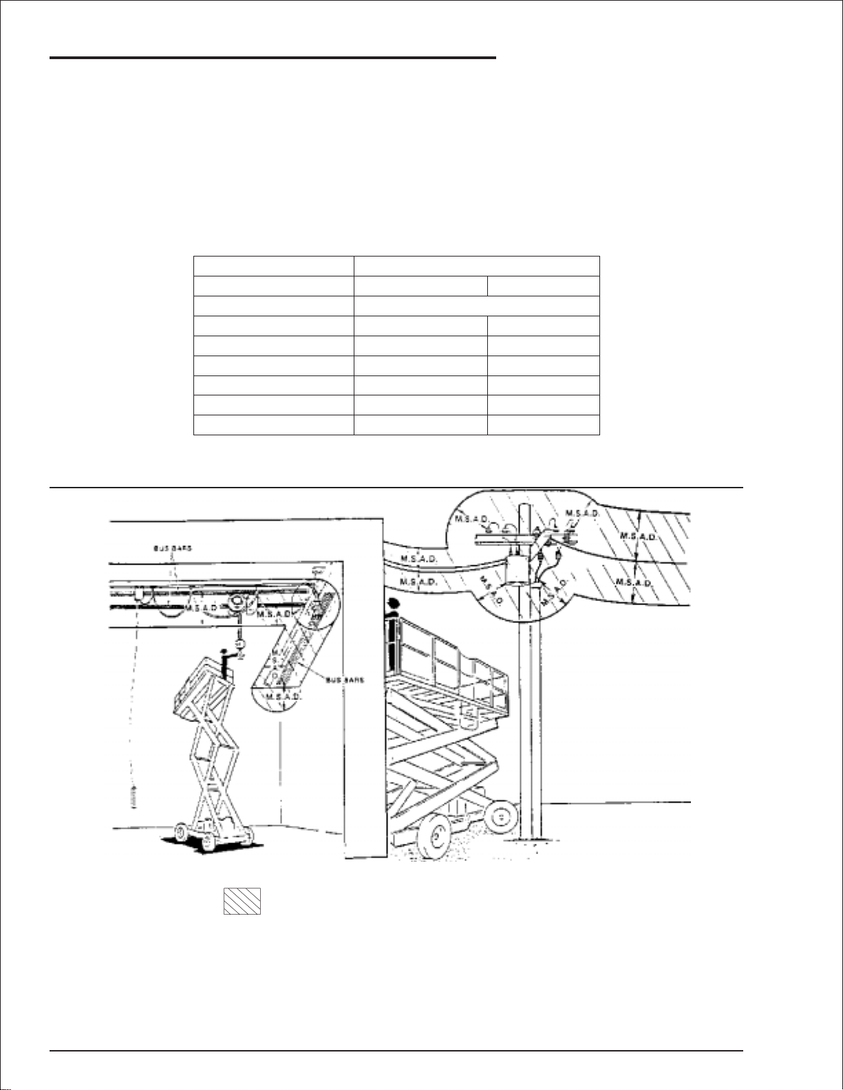
Minimum Safe Approach Distance
An SRT is an all metal NOT ELECTRICALLY INSULATED, aerial work platform. DO NOT operate it near
ELECTRICAL conductors.Regard all conductors as being energized.Use the tableand illustration below
to determine safe clearance from electrical conductors. (Table 1 and Figure 3, below, are from ANSI/SIA
A92.6–1990 Standard, reprinted with permission of Scaffold Industry Association.)
Table 1 - (M.S.A.D.)
❑
Minimum Safe Approach Distance
to energized (exposed or insulated power lines)
Voltage range Minimum safe approach distance
(phase to phase)
0 to 300V
over 300v to 50kv
over 50kv to 200kv
over 200kv to 350kv
over 350kv to 500kv
over 500kv to 750kv
over 750kv to 1000kv
(Feet) (Meters)
Avoid contact
10
15
20
25
35
45
3.05
4.60
6.10
7.62
10.67
13.72
Figure 3 - (M.S.A.D.)
❑
Denotes prohibited zone
Danger:
Caution:
- Do not allow machine personnel or conductive
materials inside prohibited zone.
- Maintain M.S.A.D. From all energised lines and parts
as well as those shown.
- Assume all electrical parts and wires are energised
unless known otherwise.
- Diagrams shown are only for purposes of illustrating
M.S.A.D. Work
ositions, not all workpositions.
page - ii SRT2670 – 11360A
Page 5
Introduction
The most important chapter in this manual is
"Safety" chapter 1. Take time, now, to study it
closely. The information in chapter 1, might save
your life or prevent serious injury.
■
Signs
The following three conventions are used through
out this manual.
1. Danger sign
DANGER
means: Attention! Become alert! Your safety is
involved.
2. Caution sign
CAUTION
means one of two things: (1) an action, about
to be performed, is potentially hazardous and
might result in minor personal injury if not
done correctly, or (2) an action, about to be
performed, can harm the SRT if not done
correctly.
3. Note sign
■
Operation rules
The following rules will help ensure the safety of
personnelandhelp preventneedlessdowntimebe
cause of damaged equipment.
1. Only TRAINED and AUTHORIZED
operators shall be permitted to operate
-
the equipment.
2. All manufacturer’s operating instructions
and safety rules and all employers’ safety
rules and all OSHA and other government
safety rules must be str ictly adhered to.
3. Repairs and adjustments shall be made
only by QUALIFIED TRAINED
maintenance personnel.
4. No modification shall be made to the
equipment without prior written consent of
the Snorkel Engineering Department.
5. You must make a pre-star t inspection of
the SRT at the beginning of each shift. A
malfunctioning machine must not be
used.
6. You must make an inspection of the work
place to locate possible hazards before
operating the SRT.
-
means: The information following is to assist
you in either the proper steps to take for an
action or as addition information concerning
your present situation, but does not indicate a
dangerous condition to either you or the SRT
unit.
■
Qualified operators
SRT aerial platforms have built in safety features
and have been factory tested for compliance with
Snorkel specifications and industry standards.
However,anypersonnelliftingdevicecanbe poten
tially dangerous in the hands of untrained or care
less operators.
Training is vitally important and MUST be done un
derthe direction of a QUALIFIEDperson.You must
displayproficiency in knowledge and actual opera
tion of the SRT.
Beforeoperation of the SRTyou must read and un
derstand the operating instructions in this manual
aswell asthe decals,warnings, andinstructionson
the machine itself.
Before operating an SRT you must be
AUTHORIZED by the person in charge to do so.
DANGER
DO NOT operate this equipment unless you
are TRAINED and AUTHORIZED and have
read and thoroughly understand all of the
information given in this Operator’s Manual
and on all DANGER and CAUTION signs on
the machine.Misuse of this machine can
result in DEATH or SERIOUS INJURY.
■
Maintenance
Every person who maintains, inspects, tests, or re
pairs these machines, and every person supervis
ing any of these functions, MUST be properly
trained.
This Operator’sManual provides a daily inspection
procedure that will help youkeep your SRTin good
operating condition. DO NOT perform other main
tenance unless you are a TRAINED mechanic,
QUALIFIED to work on the SRT. Call QUALIFIED
maintenancepersonnelifyoufind problemsormal
-
functions.
DO NOT modify this machine without written ap
proval from the Engineering Department of Snor
kel.
-
-
-
-
-
-
SRT2670 – 11360A page - iii
Page 6

Introduction
Informationcontained inthis manualconcernsonly
current SRT's, and the right is reserved to make
changes at any time without obligation.
■
Responsibilities of parties
Itis imperativethat all ownersand users oftheSRT
read, understand, and conform to all applicable
regulations.Ultimate compliance to OSHA regula
tions is the responsibility of the employer using the
equipment.
■
Additional information
For additional information, contact your local
dealer.
Snorkel
2/26 Redfern Street
Wetherill Park NSW 2164
Australia
DANGER
ANSI Standard A92.6-1990 clearly identifies
requirements of all parties who might be
involved with Self Propelled Elevating Work
Platforms.
AUSTRALIAN / NZ STANDARD AS2550-10
1994 Also identifies the requirements of all
parties who might be involved with Self
Propelled Elevating Work Platforms.
A reprint of the “Manual of Responsibilities for
Dealers, Owners, Users, Operators, Lessors
and Lessees of ANSI/SIA A92.6-1990 Self
Propelled Elevating Work Platforms” is
available from Snorkel dealers or from the
factory upon request.
Copies are also available from the Scaffold
Industry Association, Inc., 14039 Sherman
Way, Van Nuys, CA 91405-2599.
■
Options
The use of optional equipment is discussed in the
“Options” chapter 11.
Snorkel
PO Box 1041
Levin 5500
New Zealand
The options you will find discussed there are:
1. Operator Horn.
2. Outriggers.
3. RCD / ELCB Outlet.
4. Flashing Light.
5. Electrical Outlet.
6. Swinging Gate.
7. Spark Arrestor.
8. Lanyard Anchor Points.
page - iv SRT2670 – 11360A
Page 7

Table of Contents
Electrical Hazard
Electrical Hazard Warning . . . . . . . . . . . . . . . . . . i
Minimum Safe Approach Distance . . . . . . . . . . . ii
Table 1 - (M.S.A.D.). . . . . . . . . . . . . . . . . . . . . . ii
Figure 3 - (M.S.A.D.). . . . . . . . . . . . . . . . . . . . . ii
Introduction
Signs. . . . . . . . . . . . . . . . . . . . . . . . . . . . . . . . . . iii
Qualified operators. . . . . . . . . . . . . . . . . . . . . . . iii
Operation rules. . . . . . . . . . . . . . . . . . . . . . . . . . iii
Maintenance. . . . . . . . . . . . . . . . . . . . . . . . . . . . iii
Responsibilities of parties . . . . . . . . . . . . . . . . . iv
Options. . . . . . . . . . . . . . . . . . . . . . . . . . . . . . . . iv
Additional information. . . . . . . . . . . . . . . . . . . . . iv
1. Safety
Safe Operation. . . . . . . . . . . . . . . . . . . . . . . . . 1-1
Pre-start Inspection. . . . . . . . . . . . . . . . . . . . 1-1
Work Place Inspection and Practices . . . . . . 1-1
Electrocution . . . . . . . . . . . . . . . . . . . . . . . . . 1-2
Tipover and Falling Hazards . . . . . . . . . . . . . 1-2
Crushing . . . . . . . . . . . . . . . . . . . . . . . . . . . . 1-2
General Safety Precautions. . . . . . . . . . . . . . . 1-2
Personnel Precautions . . . . . . . . . . . . . . . . . 1-2
Operator General Precautions . . . . . . . . . . . 1-2
Mounting and Dismounting Precautions . . . . 1-3
Starting and Stopping Precautions . . . . . . . . 1-3
Operating Precautions . . . . . . . . . . . . . . . . . 1-3
Operator Maintenance Precautions . . . . . . . 1-3
Fuel Handling Precautions . . . . . . . . . . . . . . 1-3
Safety Decals and Placards . . . . . . . . . . . . . . 1-3
Safety Placards and Decals Location . . . . . . . 1-4
2. Safety Devices
Safety Device Information . . . . . . . . . . . . . . . . 2-1
Emergency Stop Switches. . . . . . . . . . . . . . . . 2-1
At platform control box . . . . . . . . . . . . . . . . . 2-1
At ground control box . . . . . . . . . . . . . . . . . . 2-1
Alarms . . . . . . . . . . . . . . . . . . . . . . . . . . . . . . . 2-1
Platform control box . . . . . . . . . . . . . . . . . . . 2-1
Ground control box . . . . . . . . . . . . . . . . . . . . 2-2
Level sensor . . . . . . . . . . . . . . . . . . . . . . . . . 2-2
Lowering . . . . . . . . . . . . . . . . . . . . . . . . . . . . 2-2
High temperature . . . . . . . . . . . . . . . . . . . . . 2-2
Low oil pressure . . . . . . . . . . . . . . . . . . . . . . 2-2
Drive (reverse) . . . . . . . . . . . . . . . . . . . . . . . 2-2
Drive (forward). . . . . . . . . . . . . . . . . . . . . . . . 2-2
Guardrails . . . . . . . . . . . . . . . . . . . . . . . . . . . . 2-3
Safety Prop . . . . . . . . . . . . . . . . . . . . . . . . . . . 2-3
Swinging Gate (option) . . . . . . . . . . . . . . . . . . 2-3
Safety Control . . . . . . . . . . . . . . . . . . . . . . . . . 2-3
Bubble Level (outrigger machines only) . . . . . 2-4
Operator Horn (option) . . . . . . . . . . . . . . . . . . 2-4
Outriggers (option). . . . . . . . . . . . . . . . . . . . . . 2-4
RCD/ELCB AC Outlet (option). . . . . . . . . . . . . 2-4
Flashing Light (option). . . . . . . . . . . . . . . . . . . 2-5
Lanyard Anchor Points (option) . . . . . . . . . . . 2-5
3. Specifications
General Specifications, Standard Machines . . 3-1
Engine Data. . . . . . . . . . . . . . . . . . . . . . . . . . . 3-2
Engine Oil Charts . . . . . . . . . . . . . . . . . . . . . . 3-2
WG750-G . . . . . . . . . . . . . . . . . . . . . . . . . . . 3-2
D905-B . . . . . . . . . . . . . . . . . . . . . . . . . . . . . 3-2
Nomenclature and Serial Numbers . . . . . . . . . 3-3
SRT2670 – 11360A
4. Gauges
Water. . . . . . . . . . . . . . . . . . . . . . . . . . . . . . . . 4-1
Air Filter . . . . . . . . . . . . . . . . . . . . . . . . . . . . . . 4-1
Amps . . . . . . . . . . . . . . . . . . . . . . . . . . . . . . . . 4-1
Engine Oil . . . . . . . . . . . . . . . . . . . . . . . . . . . . 4-2
Hours. . . . . . . . . . . . . . . . . . . . . . . . . . . . . . . . 4-2
Fuel Level (option). . . . . . . . . . . . . . . . . . . . . . 4-2
Hydraulic Oil Level. . . . . . . . . . . . . . . . . . . . . . 4-2
Bubble Level (outrigger machines only) . . . . . 4-3
Coolant . . . . . . . . . . . . . . . . . . . . . . . . . . . . . . 4-3
Page 8

Table of Contents
5. Automatic Shut-offs and Circuit Breakers
Automatic Shut-offs . . . . . . . . . . . . . . . . . . . . 5-1
Level sensor . . . . . . . . . . . . . . . . . . . . . . . . . 5-1
Engine temperature. . . . . . . . . . . . . . . . . . . . 5-1
Engine oil pressure . . . . . . . . . . . . . . . . . . . . 5-1
Platform height vs.drive speed. . . . . . . . . . . 5-1
Parking brakes . . . . . . . . . . . . . . . . . . . . . . . 5-1
Dynamic brakes. . . . . . . . . . . . . . . . . . . . . . . 5-1
Alternator not charging . . . . . . . . . . . . . . . . . 5-2
Outriggers (option) . . . . . . . . . . . . . . . . . . . . 5-2
Circuit Breakers . . . . . . . . . . . . . . . . . . . . . . . 5-2
Main breaker . . . . . . . . . . . . . . . . . . . . . . . . . 5-2
RCD / ELCB outlet (option). . . . . . . . . . . . . . 5-2
6. Controls
Controls . . . . . . . . . . . . . . . . . . . . . . . . . . . . . . 6-1
Hydraulic Compartment. . . . . . . . . . . . . . . . . . 6-2
Ground Control Box. . . . . . . . . . . . . . . . . . . . . 6-2
Ground control box controls . . . . . . . . . . . . . 6-3
Platform Control Box . . . . . . . . . . . . . . . . . . . . 6-4
Platform control box controls. . . . . . . . . . . . . 6-5
7. Daily Inspection and Maintenance
Daily Inspection and Maintenance Table. . . . . 7-1
Fuel level . . . . . . . . . . . . . . . . . . . . . . . . . . . . . 7-2
(Option - LPG) . . . . . . . . . . . . . . . . . . . . . . . 7-2
Fuel filter (diesel engines only) . . . . . . . . . . . . 7-2
Fuel leaks . . . . . . . . . . . . . . . . . . . . . . . . . . . . 7-2
Engine oil. . . . . . . . . . . . . . . . . . . . . . . . . . . . . 7-3
Engine coolant. . . . . . . . . . . . . . . . . . . . . . . . . 7-3
Radiator cap . . . . . . . . . . . . . . . . . . . . . . . . . . 7-3
Swinging gate (option). . . . . . . . . . . . . . . . . . . 7-3
Wiring harnesses and connectors. . . . . . . . . . 7-4
Battery terminals . . . . . . . . . . . . . . . . . . . . . . . 7-4
Hydraulic tank cap. . . . . . . . . . . . . . . . . . . . . . 7-4
Hydraulic oil level. . . . . . . . . . . . . . . . . . . . . . . 7-4
Hydraulic oil leaks . . . . . . . . . . . . . . . . . . . . . . 7-5
Tires and wheels . . . . . . . . . . . . . . . . . . . . . . . 7-5
Bolts and fasteners . . . . . . . . . . . . . . . . . . . . . 7-6
Structural damage & welds . . . . . . . . . . . . . . . 7-6
Guardrails . . . . . . . . . . . . . . . . . . . . . . . . . . . . 7-6
Lanyard anchorages (option) . . . . . . . . . . . . . 7-6
Bubble level (machines with outriggers) . . . . . 7-7
Guides, rollers, and slides . . . . . . . . . . . . . . . . 7-7
Charging system . . . . . . . . . . . . . . . . . . . . . . . 7-7
Level sensor . . . . . . . . . . . . . . . . . . . . . . . . . . 7-7
Ground controls. . . . . . . . . . . . . . . . . . . . . . . . 7-8
Emergency lowering . . . . . . . . . . . . . . . . . . . . 7-8
Platform controls . . . . . . . . . . . . . . . . . . . . . . . 7-8
Flashing light (option) . . . . . . . . . . . . . . . . . . . 7-8
RCD / ELCB (option). . . . . . . . . . . . . . . . . . . . 7-9
Air filter . . . . . . . . . . . . . . . . . . . . . . . . . . . . . . 7-9
Safety prop . . . . . . . . . . . . . . . . . . . . . . . . . . . 7-9
Parking brakes. . . . . . . . . . . . . . . . . . . . . . . . . 7-9
Placards and decals . . . . . . . . . . . . . . . . . . . 7-10
Standard placards and decals. . . . . . . . . . . 7-10
Inspection drawing . . . . . . . . . . . . . . . . . . . 7-11
8. Operation
Operating Procedures . . . . . . . . . . . . . . . . . . . 8-1
Control Stations. . . . . . . . . . . . . . . . . . . . . . . . 8-1
Emergency Stopping. . . . . . . . . . . . . . . . . . . . 8-1
Operation Considerations . . . . . . . . . . . . . . . . 8-2
Fuel type . . . . . . . . . . . . . . . . . . . . . . . . . . . . 8-2
Operating From The Ground Control Box . . . . 8-2
Raising the platform . . . . . . . . . . . . . . . . . . . 8-4
Warming the hydraulic oil . . . . . . . . . . . . . . . 8-4
Operating From The Platform Control Box . . . 8-5
Driving . . . . . . . . . . . . . . . . . . . . . . . . . . . . . 8-7
Raising the Platform . . . . . . . . . . . . . . . . . . . 8-8
Outriggers . . . . . . . . . . . . . . . . . . . . . . . . . . . . 8-8
Setting the outriggers . . . . . . . . . . . . . . . . . . 8-8
To raise the outriggers: . . . . . . . . . . . . . . . . . 8-9
Extending The Multi-Position Platform . . . . . 8-10
page - vi SRT2670 – 11360A
Page 9

9. Emergency Operation
Emergency Operation Procedures . . . . . . . . . 9-1
Emergency Stop . . . . . . . . . . . . . . . . . . . . . . . 9-1
Emergency Bleed-Down . . . . . . . . . . . . . . . . . 9-1
Pushing . . . . . . . . . . . . . . . . . . . . . . . . . . . . . . 9-3
10. Stowing and Transporting
Stowing . . . . . . . . . . . . . . . . . . . . . . . . . . . . . 10-1
Transporting . . . . . . . . . . . . . . . . . . . . . . . . . 10-2
Trailering . . . . . . . . . . . . . . . . . . . . . . . . . . . 10-2
Securing to a Transport Vehicle . . . . . . . . . 10-3
Towing . . . . . . . . . . . . . . . . . . . . . . . . . . . . 10-4
Lifting . . . . . . . . . . . . . . . . . . . . . . . . . . . . . 10-4
Pushing . . . . . . . . . . . . . . . . . . . . . . . . . . . 10-4
Winching Procedure . . . . . . . . . . . . . . . . . . 10-4
11. Options
Operator Horn . . . . . . . . . . . . . . . . . . . . . . . . 11-1
Outriggers . . . . . . . . . . . . . . . . . . . . . . . . . . . 11-1
RCD / ELCB Outlet . . . . . . . . . . . . . . . . . . . . 11-1
Flashing Light . . . . . . . . . . . . . . . . . . . . . . . . 11-1
Electrical Outlet . . . . . . . . . . . . . . . . . . . . . . . 11-2
Swinging Gate. . . . . . . . . . . . . . . . . . . . . . . . 11-2
Spark Arrestor . . . . . . . . . . . . . . . . . . . . . . . . 11-2
Lanyard Anchor Points . . . . . . . . . . . . . . . . . 11-2
Table of Contents
12. Fire Fighting and Chemical Containment
Hazardous Components . . . . . . . . . . . . . . . . 12-1
Antifreeze (UN 1993) . . . . . . . . . . . . . . . . . 12-1
Battery, Lead/Acid (UN 2794) . . . . . . . . . . . 12-1
Diesel Fuel (NA 1993). . . . . . . . . . . . . . . . . 12-1
Foam In Tires . . . . . . . . . . . . . . . . . . . . . . . 12-2
Gasoline (UN 1203) . . . . . . . . . . . . . . . . . . 12-3
Hydraulic Oil (UN 1270) . . . . . . . . . . . . . . . 12-3
Liquefied Petroleum Gas (UN 1075). . . . . . 12-4
Motor Oil (UN 1270) . . . . . . . . . . . . . . . . . . 12-4
13. Operator's Troubleshooting
Troubleshooting . . . . . . . . . . . . . . . . . . . . . . . 13-1
Operator Troubleshooting Chart . . . . . . . . . 13-1
SRT2670 – 11360A
Page 10

Table of Contents
page - viii SRT2670 – 11360A
Page 11

■
Safe Operation
The followingsafetyinformation is vitally important
forsafeoperation ofthe SRT.Failuretofollowthese
instructionscanresult inpersonalinjuryorDEATH.
1. Safety
A recommended safety practice is to have person
nel that are trained in the operation of the emer
gencycontrolsworking intheimmediate areaofthe
SRT to assist the platform operator in the event of
an emergency.
-
-
Pre-start Inspection
❑
At the start of each work shift, the SRT shall be
givena visual inspection and function test.See the
“Daily Inspection and Maintenance” chapter 7, in
this manual for a list of items to inspect and test.
CAUTION
DO NOT operate the SRT unless you are
trained and authorized, understand the
operation characteristics of the SRT, and have
inspected and tested all functions to be sure
they are in proper working order.
Work Place Inspection and Practices
❑
Do not use the SRT as a ground for welding.
Ground to the work piece.
Before the SRT is used, and during use, check the
area in which the SRT is to be used for possible
hazards such as, but not limited to:
1. Drop-offs or holes.
2. Side slopes.
3. Bumps and floor obstructions.
4. Debris.
5. Overhead obstructions and electrical
conductors.
6. Hazardous locations.
7. Inadequate surface and support to
withstand all load forces imposed by the
aerial platform in all operating
configurations.
8. Wind and weather conditions.
9. Presence of unauthorized persons.
10. Other possible unsafe conditions.
Before the SRT is used, determine the hazard clas
sification of any particular atmosphere or location
according to ANSI/NFPA 505-1987.
AnySRT operatedinahazardous location must be
approved and of the type required by ANSI/NFPA
505-1987.
When moving the platform, check the clearance
around the SRT to avoid contact with structures or
other hazards. Always look in the direction of mo
tion.
Keep ground personnel from under the platform
when the platform is raised.
Secureallaccessories,containers,tools,andother
materials in the platform to preventthem from acci
dentally falling or being kicked off the platform.
DONOTengageinany formof“horseplay”or“stunt
driving” while operating the SRT.
DO NOT permit riders on the machine anyplace
other than on the platform.
Remove all loose objects stored in or on the machine, particularly in the platform. Remove all objects which do not belong in or on the machine.
When other moving equipment is in the area, take
special precautions to comply with local regulations regarding warnings.
Never steady the platform by positioning it against
another platform.
DO NOT operate an SRT that is not functioning
properly, or has been damaged, until the machine
has been repaired by a qualified maintenance per
son.
DO NOT operate a SRT that does not have all its
decals and placards attached and legible.
Drivethemachine withcare andatspeedscompat
iblewith conditions.Use extracaution when driving
over rough ground, on slopes, and when turning.
Know and understand the job site traffic-flow pat
terns and obey the flagmen, road signs, and sig
nals.
Watchforbystanders and neverallowanyone tobe
under, or to reach through, the machine and its
equipment while operating.
Use the recommended transport device when
loading the machine.
-
-
-
-
-
-
SRT2670 – 11360A page 1 - 1
Page 12

1. Safety
Electrocution
❑
The SRT is an all metal, NON-INSULATED, aerial
work platform.
DO NOToperate it near ELECTRICAL conductors.
Regard all conductors as being energized.
DO NOT operate outside during a thunderstorm.
Tipover and Falling Hazards
❑
On scissor lifts, like the SRT, personal fall protec
tion is not required by ANSI, Fedral OSHA,
AS1418-10-1996, NZ Code of Practice for Ele
vating Work Platforms, nor Snorkel. However, fall
restraint might be required by work regulations. If
so,theuser isresponsible forfitnessand method of
use.
DONOToperatethe SRTfroma positionontrucks,
trailers, railway cars, floating vessels, scaffolds, or
similar equipment unless the application is ap
proved in writing by Snorkel.
If the platform or elevating assembly becomes
caught,snagged, or otherwise preventedfrom normalmotion by anadjacentstructureor other obstacles such that control reversal does not free the
platform, remove all personnel from the platform
beforeattemptsare madeto freethe platformusing
ground controls.
Under normal working conditions it is best not to
transfer from the platform to another structure or
vice versa, unless that is the safest way to do the
job.Each situation must be judged separately taking the work environment into account. The following guidelines apply:
1. Where possible, place the work platform
next to a roof or walking structure to do
the transfer.
2. Transfer your anchorage from one
structure to another before you step
across.
3. Remember, you might be departing the
work platform to a structure where fall
arrest is required.
4.
DO NOT climb the rails. Use the entrance.
DO NOTexceed the platform capacity nor the plat
form-extensioncapacity asindicated on the capac
ity placards located at the entrance to the platform
and on the toeboard of the platform extension.
Care shall be taken to preventrope, electric cords,
and hoses, etc., from becoming entangled in the
aerial platform.
Maintain a fir m footing on the platform floor.
Climbing on the guardrails is prohibited.
DO NOT use ladders, planks, or other devices to
extendorincrease yourworkposition fromthe plat
form.
-
DO NOTjerk the controls.Movethe controlsslowly
and deliberately to avoid jerky and erratic opera
-
tion.Alwaysstop the controls in theneutral, off, po
sition before going in the opposite direction.
DO NOT use the platform for any purpose other
than to position personnel, their tools, and materi
als.
DO NOT use the SRT as a crane, hoist, or jack.
-
DONOToperatetheSRTinwinds,orwind gusts,of
28 mph 12.5 m/s) or more.
DO NOTadd anything to the SRT that will increase
the wind loading (banners, flags, etc.).
Crushing
❑
Always look in the direction of travel. Avoid overhead obstructions.
Nevercover the floor grating or otherwise obstruct
your view below.
Make sure the area below the platform is free of
personnel before lowering.
■
General Safety Precautions
❑
Personnel Precautions
If you encounter any suspected malfunction of the
aerial platform, or any hazard or potentially unsafe
condition relating to capacity,intended use, or safe
operation, cease operation and seek assistance
from management.
❑
Operator General Precautions
Makesure that all protective guards, cowlings,and
doors are in place and secure.
-
-
Be sure the guardrail system, including the gate, is
in place and secure.
-
-
-
-
DO NOT raise the platform if the SRT is on soft
ground.Operate the platform only onafirmsurface
capable of withstanding all load forces imposed by
the aerial platform in all operating conditions.
Do Not carry loads from any point outside of the
platform.
page 1 - 2 SRT2670 – 11360A
Page 13

1. Safety
Mounting and Dismounting Precautions
❑
Use three points of support when getting on or off
theplatform(two handsandone footora similarset
of points). Keep the platform clean.
DO NOT jump off the machine.
DONOTdismountwhilethemachineisinmotion.
Starting and Stopping Precautions
❑
DO NOT start until all personnel are clearly away
from the machine.
Beforeleavingtheoperator’sstation, place the ma
chine in the stowed position.
When leaving the machine parked or unattended,
removethe starter keyfrom the Key switchand set
the Battery switch to off.
Operating Precautions
❑
DO NOT modify the SRT in any way.
Whenpartsorcomponentsare replaced,theyshall
be identical or equivalent to original Snorkel parts
or components.
DO NOT override any of the safety features of the
SRT.
❑
Operator Maintenance Precautions
DO NOTfill the fuel tank tocapacity.Allow room for
expansion.
Clean up spilled fuel immediately.
Tighten the fuel tank cap securely. If the fuel cap is
lost, replace it with an approved cap from Snorkel.
Use of a non-approved cap without proper venting
may result in pressurization of the tank.
Never use fuel for cleaning purposes.
For diesel engines, use the correct fuel grade for
the operating season.
-
■
Safety Decals and Placards
There are several safety decals and placards on
the SRT. Their locations and descriptions are
shown in this section. Take time to study them.
CAUTION
Be sure that all the safety decals and placards
on the SRT are legible. Clean or replace them
if you cannot read the words or see the
pictures.Clean with soap & water and a soft
cloth. Do not use solvents.
You MUST replace a decal or placard if it is
damaged, missing, or cannot be read. If it is
on a part that is replaced, make sure a new
decal or placard is installed on the replaced
part. See your Snorkel dealer for new decals
and placards.
CAUTION
DO NOT use your hand to search for hydraulic
oil leaks.High pressure hydraulic oil can easily
cut and penetrate your skin—averyserious
injury that requires immediate attention by a
medical specialist trained in that type of injury.
Use a piece of cardboard or wood to search
for hydraulic oil leaks.
DO NOT attempt repairs unless you are
trained.Refer to manuals and experienced
repair personnel for help.
❑
Fuel Handling Precautions
DONOTsmokeorpermitopenflames whilefueling
or near fueling operations.
Neverremove the fuel cap or refuel a gasoline en
gine while the engine is runningor hot.Neverallow
fuel to spill on hot machine components.
Maintain control of the fuel filler nozzle when filling
the tank.
Refer to Placards and Decals Inspection Chart
and Drawing in the “Daily Inspection and
Maintenance” chapter 7, for part numbers,
location, and required quantities of all placards
and decals.
-
SRT2670 – 11360A page 1 - 3
Page 14
1. Safety
■
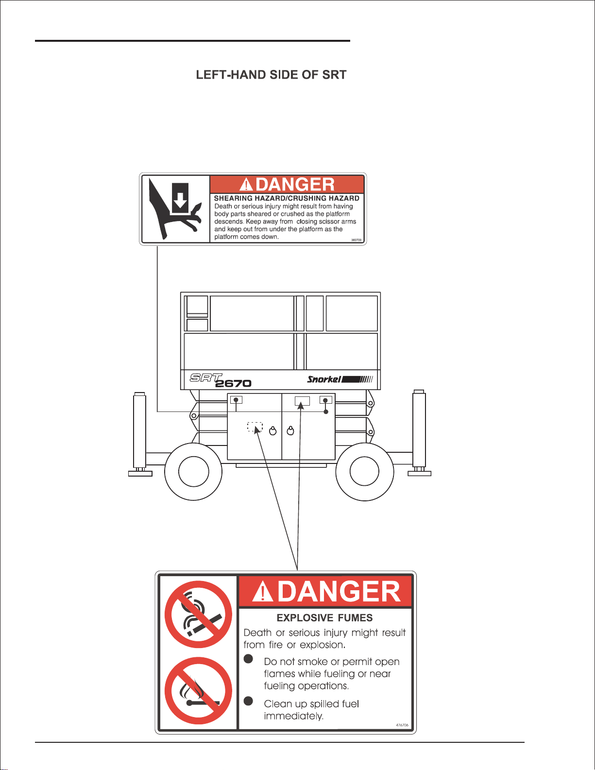
Safety Placards and Decals Location
page 1 - 4 SRT2670 – 11360A
Page 15
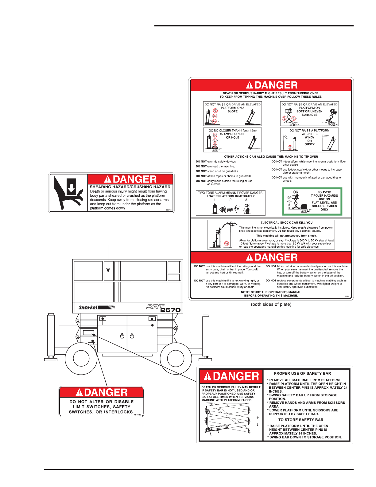
RIGHT-HAND SIDE OF SRT
1. Safety
SAFETY BAR
STORAGE POSITION
PROPER POSITION FOR USE
24”
SRT2670 – 11360A page 1 - 5
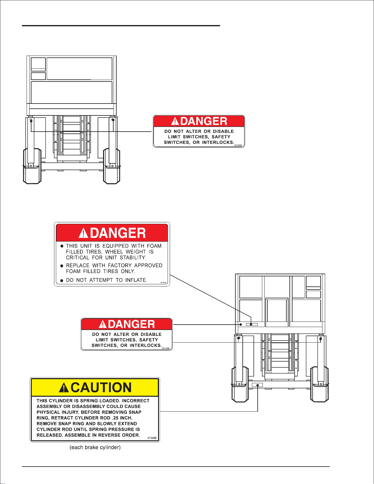
Page 16
1. Safety
FRONT END
REAR END
page 1 - 6 SRT2670 – 11360A
Page 17
2. Safety Devices
■
Safety Device Information
For emergency operation controls and procedures
see the “Emergency Operation” chapter 9, in this
manual.
The devices listed in this chapter are safety de
vices.
They are on an SRT to increase safety in the work
place for both the operator and other people near
the machine.
CAUTION
Do not by-pass, disable, modify, or ignore any
of these devices.Check them carefully at the
start of each work shift to see that they are in
working order (see “Daily Inspection &
Maintenance” chapter7). If any is found to be
defective, remove the SRT from service
immediately until a qualified service technician
can make repairs.
■
Emergency Stop Switches
❑
At platform control box
At ground control box
❑
-
Press the red EMERGENCY STOP switch cover
down, at any time, under any conditions, and the
entire machine stops, the engine turns off, and
nothing moves. the EMERGENCY STOP switch
must be up for anything on the SRT to work.
Press the large red EMERGENCY STOP button in
and the entire machine stops, the engine turns off,
and nothing moves.This switchmust be out (on) to
control the SRT from the platform (turn the switch
clockwise and it will pop out.
■
Alarms
❑
Platform control box
There are two alarms on an SRT.One is located in
the platform control box, the other is located in the
ground control box.
SRT2670 – 11360A page 2 - 1
Page 18
2. Safety Devices
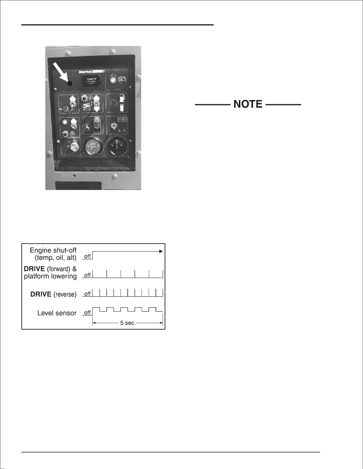
Ground control box
❑
The alarms are connected in parallel, they both
emit the same pattern of sound at the same time.
The different alarm sound patterns are shown in
the table immediately below and discussed below
the table.
Level sensor
❑
The level sensor alarm warns the SRT operator
that the SRT is not level. If the tilt continues to in
crease, the SRT will eventually tip over. When you
hear this alarm, immediately lower the platform
completely down. When the platform is completely
down, determine and correct the cause of the tilt
before raising the platform again.
While the alarm is sounding it is not possible
to drive the SRT nor raise the platform
Lowering
❑
Thelowering alarm warns people near an SRTthat
the platform is coming down and the scissor arm
assembly is closing.
High temperature
❑
Thehigh-temperature alarm warns youthat the engine is overheating. When the alarm sounds you
should immediately lower the platform completely
downthenturn theengineoff untilthecondition that
caused the overheating has been corrected. (See
“AutomaticShut-Offs & Circuit Breakers”chapter 5
for more information.)
-
The high-temperature, low oil-pressure, and alter
nator not-charging alar ms are each a continuous
tone.
The DRIVE (forward) and the platform-lowering
alarms beep at one beep per second. DRIVE (re
verse) beeps at two beeps per second. The level
sensor alarm is a high-low warbling sound.
❑
Low oil pressure
The low pressure alarm warns you that the engine
oilpressure isnear the lowerlimitfor safeoperation
of the engine. When the alarm sounds you should
immediately lower the platform completely down
then turn the engine off until the condition that
caused the low oil pressure has been corrected.
(See “Automatic Shut-Offs & Circuit Breakers”
chapter 5 for more information.)
❑
Drive (reverse)
The DRIVE (reverse) alarm alerts people that the
SRT is traveling backward along the ground. This
-
alarm beeps twice as fast as the DRIVE (forward)
alarm.
❑
Drive (forward)
-
The DRIVE (forward) alarm alerts people that the
SRT is traveling forward along the ground. This
alarm beeps half as fast as the DRIVE (reverse)
alarm.
page 2 - 2 SRT2670 – 11360A
Page 19
2. Safety Devices
■
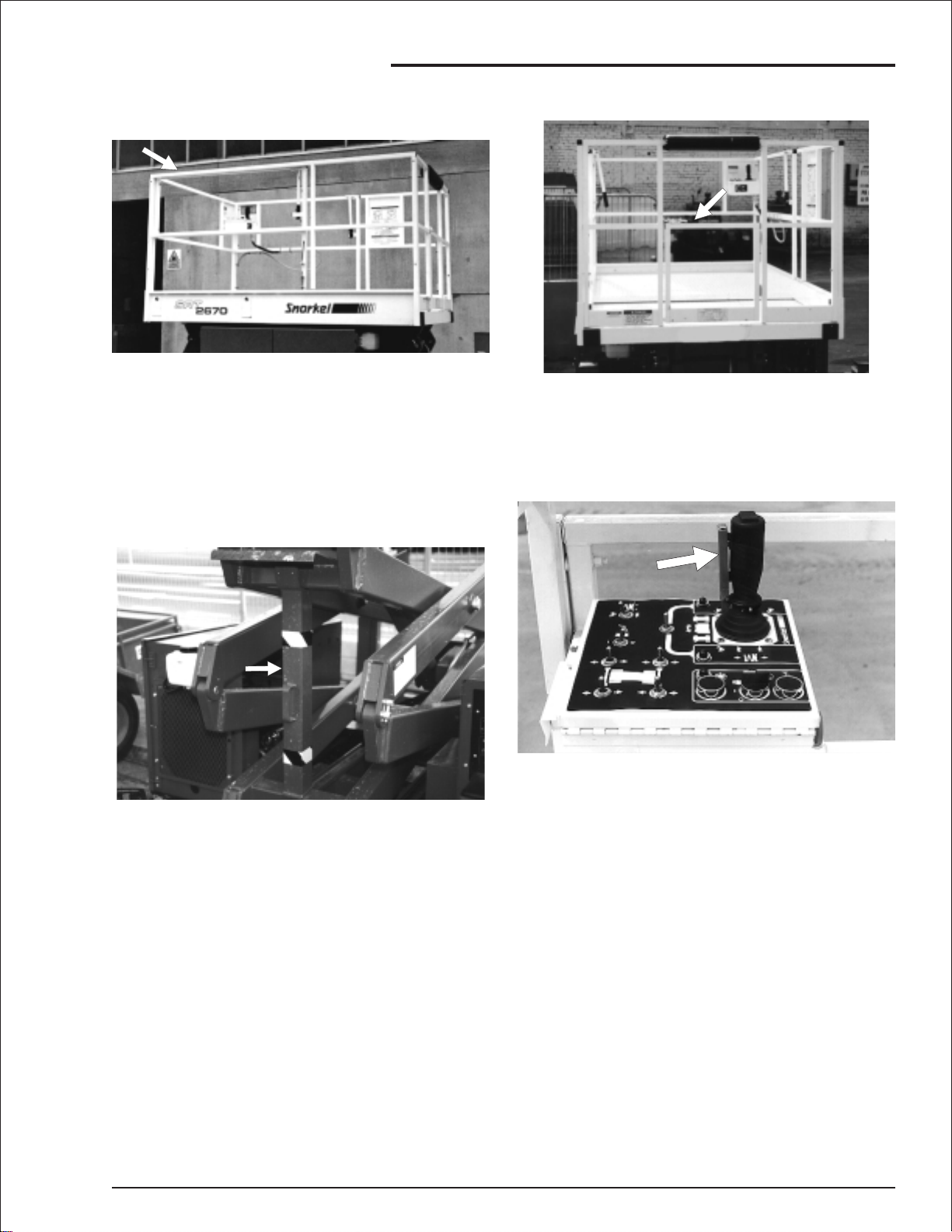
Guardrails
The guardrails help protect you from falling off the
platform. Be sure the guardrails are properly in
stalled and that the safety chain (or gate) and fas
teners are in place.
■
Safety Prop
■
Swinging Gate (option)
The swinginggate should be closed atall timesex
cept when someone is entering or leaving the plat
form.
-
■
Safety Control
-
-
The safety control must be squeezed and held to
activatethejoystick.Thesafetycontrolpreventsthe
joystickfrom movingtheplatform ifsomethingacci
Always raise the safety prop then lower the scis
sor-arm assembly onto the safety prop before
reachingintothe scissor-arm assemblyforanyrea
son.The safety chain should be closed at all times
except when someone is entering or leaving the
platform.
SRT2670 – 11360A page 2 - 3
-
dentally pushes the joystick. Do not disable the
safety control in any way.
-
-
Page 20
2. Safety Devices
■
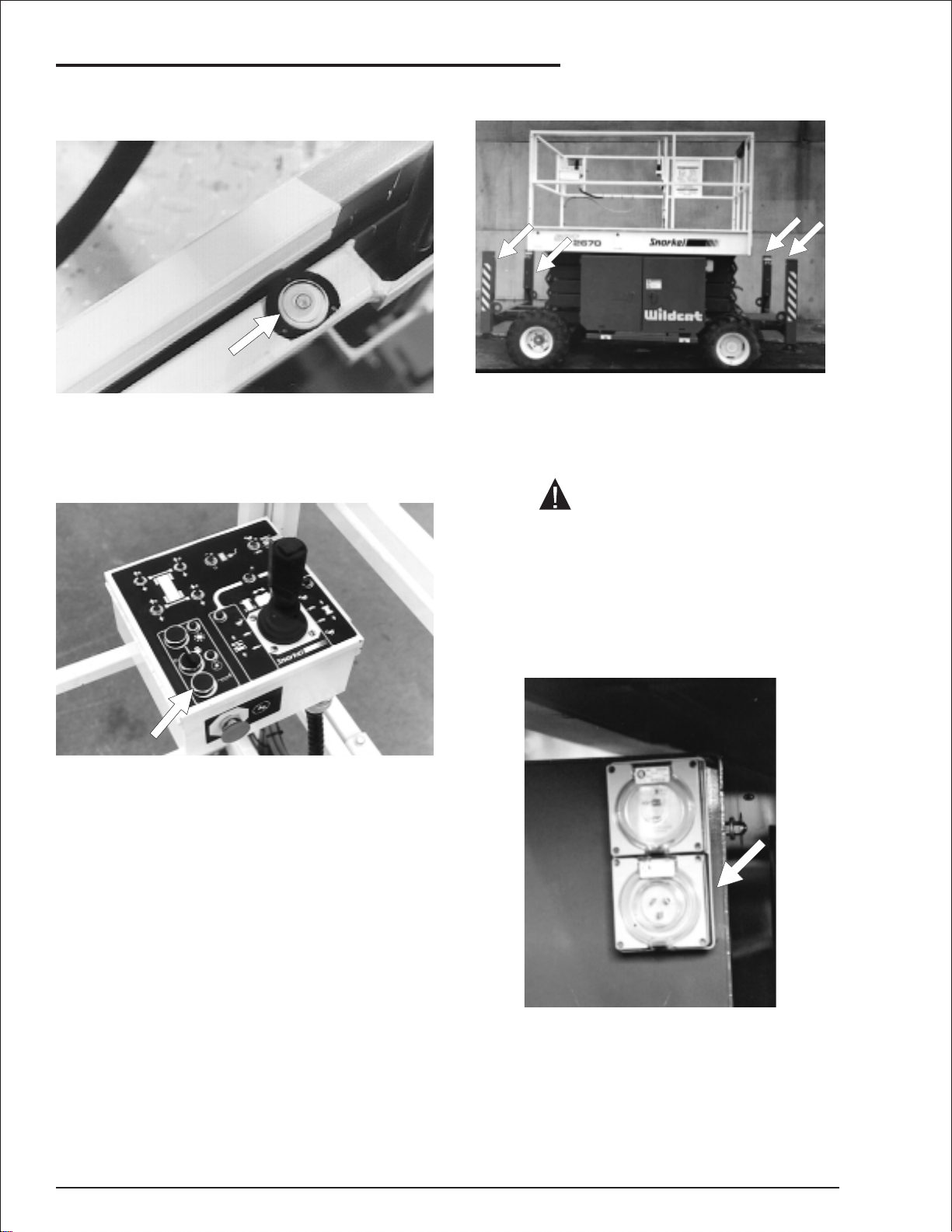
Bubble Level (outrigger machines
only)
See the “Gauges”chapter 4 for a discussion of the
bubble level.
■
Operator Horn (option)
■
Outriggers (option)
The outr igger controls are on the upper left side of
theplatform control box.The outriggers are usedto
leveltheSRT(forcomplete outriggeroperatingpro
cedures see the “Operation” chapter 8).
CAUTION
The SRT must be on a firm surface capable of
withstanding all load forces imposed by the
aerial platform in all operation conditions
before the outriggers are used.
-
Theoperatorhornisused primarily toget theatten
tion of people on the ground when you are working
aloft.Forthe horn towork thefollowingswitches,on
the ground control box, must be set as indicated:
MAIN POWER........................ON
EMERGENCY STOP..............on (up)
SELECTOR............................PLATFORM
■
RCD/ELCB AC Outlet (option)
-
page 2 - 4 SRT2670 – 11360A
Page 21
The RCD (Residual Current Device) is located at
the ground and will protect against short circuits to
earth. When there is a short circuit the RCD will
shutdownthe 230vACpowerto theplatform outlet.
To reset the outlet disconnect the power tool lead
from the platform box and reset the RCD at the
ground.Ifthe problempersistscalla trainedservice
technician.
■
Flashing Light (option)
2. Safety Devices
The flashing light alerts people that the SRT is
present and that the SRT is moving. The light
flashes at about one flash per second any time the
SRTengine is running.There is no ON/OFF switch
for the flashing light, it cannot be turned off while
the SRT is running.
■
Lanyard Anchor Points (option)
There are four anchors on the floor of the platform,
one at the front of the roll-out deck, one at the back
of the platform, and one on each side of the plat
form.
These anchors are not for lifting or tying down
the machine.
Youshouldattachyourfallprotectionto theanchors
if work rules require it.
-
SRT2670 – 11360A page 2 - 5
Page 22

2. Safety Devices
page 2 - 6 SRT2670 – 11360A
Page 23

3. Specifications
3. Specifications
The SRT2670 series machines are scissor-supported elevatingwork platforms built to conform to the fol
lowing standards.
OSHA Paragraph1910.67 Title 29, C.F.R.,Vehicle-MountedElevating and Rotating Work Platforms - La
bour.
OSHA Paragraph 1926.556 Title 29, C.F.R., Aerial Lifts - Construction.
Australian Standard AS1418-10 1996 Elevating Work Platforms.
■
General Specifications, Standard Machines
SPECIFICATIONS SRT 2670
Nominal working height
Maximum height to basket floor
Maximum outreach 1220mm with roll out deck
Speed (when raised)
Speed (maximum drive)
Maximum width of base
Safe working load (main deck)
9.9m 31’10”
7.9m 25’11”
0.72kph 0.45mph
6.2kph 3.9mph
1.8m 5’11”
390kg 858lbs
-
-
Safe working load (roll out deck)
Standard colour White platform. Orange scissors and base
Platform size*
Collapsed height
Overall length (without stabilizers)
Overall length (with stabilizers)
Gradeability
Lift time
Lower time
Turning radius (inner)
Turning radius (outer)
Insulation rating
Overall weight
Ground clearance
120kg 264lbs
1655 x 2200mm 5’5” x 7’ 4”
2525mm 8’1”
2680mm 8’ 10”
3325mm 10’10”
30%
22 seconds
45 seconds
2.56m 8’3”
4.3m 14’1”
Nil
2560kg 5632lbs
361mm 14.2”
* Four foot (1.2m) platfrom-extenuation retracted
SRT2670 – 11360A page 3 - 1
Page 24
3. Specifications
■
Engine Data
Engine Make Kubota
Model WG750-G D905-B
Fuel gasoline LPG Diesel number 2-D
Fuel grade Unleaded
HD5
ASTM number 2-D
85 octane
(motor method
Gas Processors
ASTM D975
Association
Do not use
gasoline blended
with methyl
alcohol.
Standard 2140
Category: special
duty propane
Centane number >44
(For operating temp. Below 32
use “winterized” number 2-D.)
Coolant 50% water + 50% ethylene glycol
Operating
180oF - 205oF (82oC-96oC)
temperature
Oil Capacity 3.5 qt USA
(3.25 liters)
5.2 qt USA
(5.1 liters)
Oil grade API: SF, SF/CD API: CC/CD/CE
Oil weight See chart below
Running time
(one tank of fuel)
A full tank of gasoline, or diesel, will last an entire eight hour shift, under normal
working conditions.It normally takes two tanks of LPG per eight hour shift.
4.2 qt USA
(4.0 liters)
o
F(0oC)
■
Engine Oil Charts
❑
WG750-G
Ambient temperature Engine oil weight
Above 77
o
32
Fto77oF
o
(0
C) to (25oC)
o
0
Fto32oF
(-17
o
F (25oC) SAE30 or 10W30
SAE20 or 10W30
o
C) to (0oC)
SAE10W or 10W30
❑
D905-B
Ambient temperature Engine oil weight
Above 77
o
F (25oC) SAE30 or 10W30
10W40
o
Fto77oF
32
o
(0
C) to (25oC)
Below 32
o
F(0oC) SAE10W or 10W30
SAE20 or 10W30
10W40
10W40
page 3 - 2 SRT2670 – 11360A
Page 25

■
Nomenclature and Serial Numbers
3. Specifications
SRT2670 – 11360A page 3 - 3
Page 26

3. Specifications
page 3 - 4 SRT2670 – 11360A
Page 27

■
Water
4. Gauges
Theindicator stays at its highestsetting, it does not
go to the bottom of the gauge when the engine is
turned off or the filter changed. After the filter is
changed, press the small reset button to reset the
indicator to the bottom of the gauge.
■
Amps
The water gauge is located on the ground control
box. It shows the temperature of the water-antifreezemixture in the engine block.The typical operating-temperature range for Kubota
enginesis 180°F to205°F (82°C to96°C), both diesel and gasoline.(See the “Automatic Shut-Offs &
Circuit Breakers ” chapter 5 for more information.)
■
Air Filter
The AMPS gauge shows the electric current from
the alternator to the battery. When the engine is
running, the needle in the AMPS gauge should not
be to the left of “0.” Under normal operating conditions, after the engine has been running for a few
minutes, the AMPS gauge should read “0.”
The air filter gauge is located between the air filter
and the intake manifold.The gauge measures the
vacuum(air pressure) between the intake manifold
and the air filter. As the filter clogs, the vacuum in
creases (pressure drops). As the vacuum in
creases, a red indicator raises toward the clear
area of the gauge.When you can see the indicator
inthecleararea ofthegauge,it’stimetochange the
air filter.
SRT2670 – 11360A page 4 - 1
-
-
Page 28

4. Gauges
■
Engine Oil
Engine oil levelis measured with a dipstick. Oil ca
pacities given in the “Specifications” chapter 3 are
approximate.True values will vary from machine to
machine due to slight variations or modifications
during production.
The oil dipstick is the only way to accurately
gauge if the engine oil level is correct.
Engine oil level should always be between the
lines on the dipstick - never above the top line
or below the bottom line.
Gasoline Diesel
The HOURS gauge is basically an electric clock.It
accumulates time only when the engine is running.
The HOURS gauge cannot be reset. An
SRT-qualifiedservicetechnician usesitto tellwhen
it is time for the periodic maintenance listed in the
Maintenance Manual.
■
Fuel Level (option)
LPGtanks havetwo fuel gauges (1) (2) ontop.One
measures correctly when the tank is standing on
end (VERTICAL) the other measures correctly
whenthe tank is layingdown (HORIZONTAL).Both
read in fractions-of-a-full-tank. SRT tanks are
mounted vertically. Therefore, you should read the
VERTICAL (1) scale.
■
Hours
■
Hydraulic Oil Level
The hydraulic-oil level gauge is on the side of the
hydraulic oil tank. It shows the actual level of oil in
side the tank. Read it only when the platform is
completely down. Otherwise, the lift cylinders be
come large reservoirs for hydraulic oil and the oil
level in the tank will be low.The oil level should be
within ( 0.25 inches (( 6.4 mm) of the line.
-
-
page 4 - 2 SRT2670 – 11360A
Page 29

■
Bubble Level (outrigger machines
only)
A bubble level is located on the platform side rail,
below the platform control box. Watch the bubble
levelwhile you set the outriggers.Lower the outrig
gers,oneata time,justenough tocenter thebubble
inthe circle ontop of thegauge.When thebubbleis
centered the platform is level and can safely be
raised.
4. Gauges
-
■
Coolant
The engine coolant reservoir is mounted on the
front of the engine tray.When the engine is at oper
atingtemperaturethe coolantshouldbe atthe HOT
line.When the engine is cold there should beabout
one inch (2.54 cm) of coolant in the bottom of the
reservoir.
-
SRT2670 – 11360A page 4 - 3
Page 30

4. Gauges
page 4 - 4 SRT2670 – 11360A
Page 31

5. Automatic Shut-offs and Circuit Breakers
■
Automatic Shut-offs
Level sensor
❑
When the levelsensor alarmsounds, automatic in
terlocksmakeitimpossibletodrivethe SRTorraise
the platform. For more complete information see
the “Level Sensor” subsection of the “Safety De
vices ” chapter.2
Engine temperature
❑
There is an oil pressure sensor in the engine. It
measures the engine oil pressure at the oil filter.If
the pressure falls below a safe operating value the
engine shuts off. The engine will restart with low
-
pressure but it will only run a few seconds before it
automatically shuts off again.
-
Platform height vs. drive speed
❑
When the platform is over 1.7m (5’ 6") above the
ground the drive speed is limited to its slowest
speed and the engine revs are also automatically
lowered.
Parking brakes
❑
Thereisatemperaturesensorinthe engine.Itmeasures the temperature of the antifreeze-water mixtureasthemixture leavesthetop oftheradiatorand
enters the top of the engine. If the temperature
reaches 210(F (99(C) an alarm sounds.If the temperature continues to rise, the engine shuts off
when the temperature reaches 230(F (110(C). The
engine will not restart until the temperature drops
below 210(F (99(C).
❑
Engine oil pressure
Whenthe JOYSTICKCONTROLLER is in the neutral position the SRT parking brakes are automatically set. The brakes automatically release when
youmovetheJOYSTICKCONTROLLERto drive.
❑
Dynamic brakes
When you drive an SRT down a slope, if the SRT
begins to coast (outrun the drive motors) the hy
draulicsystem“senses”thecoastingcondition.The
hydraulic drive motors then become hydraulic
brakesand the SRTis slowed.Thisaction prevents
SRTs from speeding down grades.
-
SRT2670 – 11360A page 5 - 1
Page 32

5. Automatic Shut-offs and Circuit Breakers
Alternator not charging
❑
When the fan belt breaks, or the alternator output
fallsbelowasafelevelforotherreasons,the engine
automatically shuts off and an alarm sounds. As
long as the SRT battery is charged you can lower
the platform, in the usual way, from the platform
control box or the ground control box without the
engine running.
Outriggers (option)
❑
The SRT cannot be driven unless the outriggers
arecompletely up.If youhavejustraised the outriggers but the SRT will not drive, double check to be
sure all four outriggers are completely up.
RCD / ELCB outlet (option)
❑
RESET
BUTTON
The RCD (Residual Current Device) is located at
the ground and will protect against short circuits to
earth. When there is a short circuit the RCD will
shutdownthe 230vACpowerto theplatform outlet.
To reset the outlet disconnect the power tool lead
from the platform box and reset the RCD at the
ground.
If the problempersists call a trained service technician.
■
Circuit Breakers
❑
Main breaker
There is only one circuit breaker, on a standard
SRT, that is accessible to the operator.Its purpose
is to protect the electrical circuits from electrical
overloads.Whenthe circuit breakertrips(pops out)
push it back in then attempt to use the SRT. If the
circuitbreakertrips asecondtime,takethe SRTout
of service and refer the problem to a qualified
trained service technician for repair.
page 5 - 2 SRT2670 – 11360A
Page 33

■
Controls
This chapter explains what each control does.
6. Controls
This chapter does not explain how to use the con
trolstoproduceuseful work,refertothe“Operation”
chapter8forthat,afteryouhavereadthischapter.
Foroptional-equipment controls, see the “Options”
chapter 11 .
The only optional-equipment controls discussed in
this chapter are the controls for: diesel engines,
dual-fuelengines,LP-onlyengines,andoutriggers.
See the “Emergency Operation” chapter 9 for the
location of the emergency bleed down control and
for correct emergency bleed down procedures.
The main operating functions of an SRT can be
controlled from the ground control box (1) or the
platform control box (2).
-
SRT2670 – 11360A page 6 - 1
Page 34

6. Controls
■
Hydraulic Compar tment
1.
Battery Switch: This must be ON for the
engine to start. When the battery switch is
OFF the positive side of the SRT battery
is disconnected from the electrical
system. Lock this switch OFF when the
SRT is left unattended.
■
Ground Control Box
Controls for operating an SRT from the ground are
located on the right side ofthe machine on the rear
of the hydraulic compar tment.
The number of each control below
corresponds to the control’s call-out on the
next page.
1.
Emergency Stop: Press the red
switch-cover down, at any time, under any
conditions, and the entire machine stops the engine turns off and nothing moves.
This switch must be up for anything on
the machine to work.
2.
Key Switch: This switch works like an
automobile ignition switch.Hold the key at
the start symbol (extreme clockwise
position) until the engine starts then
release it to the on position (bar
symbol).Turn the key to off (O) if the
platform is to stay in one position for a
long time.That will turn the engine off and
save fuel.
3.
Choke Indicator Light (gasoline engines
only): This light will be lit while you choke
the engine (see CHOKE below).
3.
Glow-Plug Indicator Light (diesel
engines only): This light will be on while
the glow plugs are on. Wait, about 30
seconds for the light to go out before you
try to start a diesel.
4.
Choke (gasoline engines only): Hold the
choke switch up anytime you start a
gasoline engine that is at ambient air
temperature (a “cold” engine).
4.
Glow Plug (diesel engines only): This is a
momentary contact switch. Press it up
then release it just before you start a
diesel engine that is at ambient air
temperature (a “cold” engine). This action
automatically causes glow plugs to come
on for 30 seconds to warm the inside top
of each cylinder, thus aiding combustion.
5.
Hydraulic Oil Warm-Up:When the
ambient air temperature is below 50°F
(10°C) and SRT movement is sluggish
because of cold hydraulic oil, turn the
warm-up switch on (up) for 5 to 10
minutes or until the hydraulic oil tank is
warm to the touch then turn the switch off
(down).For the warm-up system to work,
the engine must be running.
While the warm-up system is on, do not
attempt to move the SRT in any way.
6.
Lift Indicator Light: The platform can be
raised only when this light is lit. When this
light is not lit the platform will not rise
because: the platform is not level, or the
outriggers are not properly set.
7.
Platform Lift/Lower: Holding this switch
up causes the platform to rise. Pushing
this switch down causes the platform to
lower.
8.
Fuel (option): Before starting a dual-fuel
engine set the FUEL switch to gasoline
(up) or LP gas (down) depending on
which you want to use. If you select LP
gas, be sure to open the valve on top the
LP gas tank.
9.
Ground/Platform Selector: Must be
down for the ground control box to work.
Must be up for the platform control box to
work.
page 6 - 2 SRT2670 – 11360A
Page 35

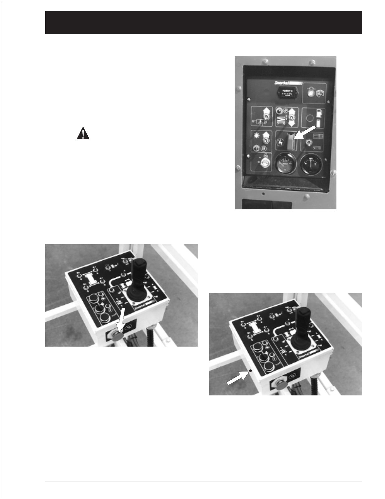
Ground control box controls
❑
6
6. Controls
7
5
4
3
8
9
1
2
SRT2670 – 11360A page 6 - 3
Page 36

6. Controls
■
Platform Control Box
Controlsforoperatingan SRTfromthe platformare
located on the platform control box.
The number of each control below
corresponds to the control’s call-out on the
next page.
1.
Emergency Stop: Press the red button in
at any time, under any conditions, and the
entire machine stops - the engine turns
off and nothing moves. This switch must
be out (on) to start and run the SRT from
the platform control box, turn the switch
clockwise and it will pop out (on). Press
the switch in (off) if the platform is to stay
in one position for a long time. That will
turn the engine off and save fuel.
5.
Safety Control The SAFETY CONTROL
must be squeezed against the JOYSTICK
CONTROLLER to activate the joystick
controller.If the safety control is not
squeezed the joystick controller is
inoperative.
6.
Joystick Controller If the LIFT/DRIVE
SELECTOR is set to the left (lift function),
pushing the joystick controller forward
causes the platform to rise, pulling the
joystick controller backward causes the
platform to lower. If the LIFT/DRIVE
SELECTOR is set to the right (drive
function), pushing the joystick controller
forward causes the SRT to move forward,
pulling the joystick controller backward
causes the SRT to move backward.The
further you push or pull the controller the
faster the motion (except lowering-it
occurs at one speed only).
The EMERGENCY STOP switch on the
ground control box overrides the one on the
platform control box.If the one on the ground
control box is off the SRT will not start or run,
it does not make any difference whether the
one on the platform control box is on or off.
2.
Start Press and hold the switch in to start
the engine.As soon as the engine starts,
release the switch.
3.
Choke (gasoline engines only): Press
and hold the switch in anytime you start a
gasoline engine that is at ambient air
temperature (a “cold” engine).
3.
Glow-Plug (diesel engines only): This is a
momentary contact switch. Press it up
then release it just before you start a
diesel engine that is at ambient air
temperature (a “cold” engine). This action
automatically causes glow plugs to come
on for 30 seconds to warm the inside top
of each cylinder, thus aiding combustion.
4.
Choke Indicator Light (gasoline engines
only): This light will be lit while you choke
the engine.
4.
Glow-Plug Indicator Light (diesel
engines only): This light will be on while
the glow plugs are on. Wait for the light to
go out before you try to start a diesel.
Squeeze the SAFETY CONTROL anytime you
use the JOYSTICK CONTROLLER.
7.
Steering The rocker switch on top of the
JOYSTICK CONTROLLER turns the front
wheels left or right depending upon which
side of the switch you press.
The wheels do not return to straight ahead,
after a turn, the way automobile wheels do.
You must use the STEERING switch to
straighten the wheels after a turn.
8.
Lift/Drive Selector When this switch is
set to the left the JOYSTICK
CONTROLLER becomes a lift/lower
controller to raise or lower the platform.
When this switch is set to the right the
JOYSTICK CONTROLLER becomes a
drive controller to drive the SRT forward
or backward.The SRT will not drive and
lift at the same time.
9.
Speed Set the switch to turtle (slow)
when you are working in close quarters or
if you are new to the machine. Setting the
switch to rabbit (fast) doubles the top
speed of the SRT.
10.
AC Outlet Switch (option): This is an
on/off switch for the 230 V ac hydraulically
powered generator.When the switch is
on, the outlet box at the platform is
energized.
page 6 - 4 SRT2670 – 11360A
Page 37

6. Controls
11.
Lift Indicator Light The platform can be
raised only when this light is lit. When this
light is not lit the platform will not rise
because: the platform is not level, or the
outriggers are not properly set.
12.
Outriggers Each switch corresponds to
one of the outriggers. Pull a switch
backward to lower an outrigger, push it
forward to raise the outrigger.
Platform control box controls
❑
13.
Drive Indicator Light The platform can be
driven when this light is lit. When it is not lit
the platform will not drive because with the
platform raised the base is not level or with
the platform raised the axle switches are not
set.
SRT2670 – 11360A page 6 - 5
Page 38

6. Controls
page 6 - 6 SRT2670 – 11360A
Page 39

7. Daily Inspection and Maintenance
At the start of each work day (or 8 hour shift), an
SRT qualified operator must perform the Daily In
spection and Maintenance as listed in the table be
Defective par ts and/or equipment malfunctions
jeopardizethe safety of the operator and other per
sonnel, and can cause damage to the machine.
-
low.
The purpose of the Daily Inspection and Mainte
nance is to keep the SRT in proper working condi
tion and to detect signs of malfunction at the
earliest possible time.
Set the Key Switch set to OFF before you begin
this inspection.
■
Daily Inspection and Maintenance Table
-
-
DO NOT operate an SRT that is known to be
damaged or malfunctioning.
Repair all equipment damage or malfunctions,
before placing the SRT into service.
DANGER
Item Service Required
Fuel level Visually inspect
Fuel filter (diesel engines only) Visually inspect (condition)
Fuel leaks Visually inspect (hoses and connections etc)
Engine oil Check oil level (between dipstick lines)
Engine coolant Check fluid level and radiator hoses
Radiator cap Visually inspect installation)
Platform safety chain Visually inspect (operation)
Swinging gate Visually inspect (installation, operation)
Wiring harnesses and connectors Visually inspect (installation, operation)
Battery terminals Visually inspect (no corrosion)
Hydraulic tank cap Visually inspect installation)
Hydraulic oil level Check fluid level (at line on side of tank)
Hydraulic oil leaks Visually inspect (hoses,tubes)
Tires and wheels Visually inspect (condition)
Bolts and fasteners Visually inspect (looseness)
Structural damage and welds Visually inspect (welds, cracks, dents)
Guardrails Visually inspect (condition)
Lanyard anchorages (option) Visually inspect (condition)
Bubble level on platform (outrigger machines) Visually inspect (condition)
Guides, rollers and slides Visually inspect (condition)
START THE ENGINE FROM THE GROUND CONTROL BOX
Charging system Check condition (gauge)
Level sensor Check operation
Ground controls Actuate and visually inspect for operation
Emergency lowering Check operation (causes correct motion)
Platform controls Actuate and visually inspect for operation
Flashing light (option) Visually check (operation)
RCD / ELCB (option) Check operation
Air filter Check condition (gauge)
Safety prop Check operation
Parking brakes Check operation
Placards, decals, and Operators Manual Visually inspect (installation and condition)
-
SRT2670 – 11360A page 7 - 1
Page 40

7. Daily Inspection and Maintenance
The rest of this chapter shows how to perform the
inspectionand maintenance required for each item
in the daily inspection and maintenance table.
■
Fuel level
■
Fuel filter (diesel engines only)
Visually check to see that there is no water in the
bottom of the filter.
Remove the fuel tank cap. Visually Check to see
that the gasoline or diesel tank is full.
Replace the tank cap and tighten.
❑
(Option - LPG)
To check the fuel read the fuel meter (4) on top.
■
Fuel leaks
To replace an LPG tank: Close the valve (1).
Manually disconnect the fuel hose at the knurled
ring (2). Manually lift the tank (3) out.
page 7 - 2 SRT2670 – 11360A
Page 41

7. Daily Inspection and Maintenance
Visually inspect the entire length of the fuel line,
from the engine to the fuel tank, for leaks.
■
Engine oil
Keepthe oillevelbetweenthe markson thedipstick
(1).
The distance between the top and bottom dipstick
markscorresponds toabout1qt.(one liter).Add oil,
if needed at the cap (2) on top of the engine.
Turn the engine OFF at the ground control box box
KEYSWITCH.Removethecap(2) fromthecoolant
reservoir.Add coolant and replace cap.
■
Radiator cap
Visually check to see that the cap is in place and
tight.
■
Swinging gate (option)
See the “Specifications” chapter 3 for the
correct engine oil grade and weight.
■
Engine coolant
The Kubota engine is liquid cooled. At operating
temperatures the coolant should be at the HOT
level(1).When cold there should be approximately
1inch (2.5cm) of coolantin the bottomof the reser
voir.
Inspect the gate to see that it swingsfreely,latches
securely, and is not deformed in any way.
-
Thecoolantishalf waterandhalfethyleneglycol.
To add coolant:
SRT2670 – 11360A page 7 - 3
Page 42

7. Daily Inspection and Maintenance
■
Wiring harnesses and connectors
Inspect all the wiring harnesses, on the machine,
for loose connections, broken wires, and frayedin
sulation.
■
Battery terminals
Batteryterminalsshould beclean andfreeofcorro
sion — none of that greenish-white fuzzy stuff.
-
■
Hydraulic tank cap
-
Check to see that the cap is in place and is tight.
■
Hydraulic oil level
To check the hydraulic oil level:
Payparticular attentiontothe wiringharnessesthat
are attached to the scissor stack.
page 7 - 4 SRT2670 – 11360A
Completely lower the platform.
Page 43

The hydraulic oil level should be at the full level. If
necessary, add hydraulic oil at the Hydraulic oil
tankcap.Seethe “Specifications”chapter3fortype
and grade of hydraulic oil.
■
Hydraulic oil leaks
DANGER
Leaking hydraulic oil can cause burns, fires,
falls (slipping), cuts, and puncture wounds (if
under high pressure). Do not tolerate hydraulic
oil leaks.They are dangerous.
Hydraulic oil leaks are easily visible and can show
up anyplace.
Visuallyinspect the entire machinefor hydraulicoil.
Checkthegroundunderthemachine forleakedoil.
7. Daily Inspection and Maintenance
Check for loose fittings at the valve.
Pay particular attention to the cylinders, check to
see that there is no oil leaking from the seal, also
check all hoses that run to the cylinders.
■
Tires and wheels
SRT tires are foam filled. Punctures of the type
causedby bolts, screws,or nails are not a problem.
Look for large holes or long cuts completely
through the tire body: holes or cuts where foam is
being forced or eroded out of the tire.Also look for
large imbedded objects, such as angle iron, that
can rip a tire body open under some conditions.
SRT2670 – 11360A page 7 - 5
Page 44

7. Daily Inspection and Maintenance
■
Bolts and fasteners
Visually inspect all fasteners to see that none are
missing or obviously loose.
Visually inspect all welds for cracks, all structural
members for deformity, and all sheet metal for
dents that could interfere with machine operation.
■
Guardrails
Pay particular attention to all of the wheel nuts.
None should be visibly loose, missing, or de
formed.
■
Structural damage & welds
Payparticular attentiontothe guardrails.Makesure
theguardrails areproperly installed, thatall the fas
teners are in place,and that the swinging gate is in
place and works properly.
■
Lanyard anchorages (option)
Check all four lanyard anchorages on the floor of
the platform to see that they are present, not de
formed, that they movefreely,and that they are se
curely attached to the platform.
-
-
-
page 7 - 6 SRT2670 – 11360A
Page 45

7. Daily Inspection and Maintenance
■
Bubble level (machines with
outriggers)
Visually check to see that the bubble level is not
damaged, that it is full of fluid, that the bubble does
not exceed the diameter of the center black circle,
and the surface on which the bubble level is
mounted is not deformed or bent out of level.
■
Guides, rollers, and slides
Visually check slides (1), and rollers (3) forwear or
damage.Be sure that the guides (2) are free of de
bris and allow the slides and rollers to move
smoothly.
■
Charging system
-
With the engine idling, the needle in the AMPS
gauge should not be to the left of “0" (left of ”0" is
discharging).
2
1
Leave the engine running for the next step
■
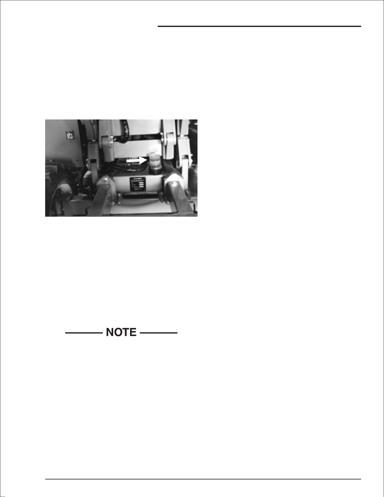
Level sensor
With the SRT engine running and scissors raised,
push the levelsensor to the side as faras possible.
The level sensor alarm should sound.
SRT2670 – 11360A page 7 - 7
Page 46

7. Daily Inspection and Maintenance
■
Ground controls
Checkthe Platform Lift/Lower switch(1) to see that
it is functioning properly by holding the switch up to
rise platform and pushing the switchdown to lower
the platform.
In cold temperatures (below 50(F/10(C ) check to
see that the Hydraulic Oil Warm-Up switch (2) is
functioning properly by turning the switch on (up)
for 5 to 10 minutes or until the hydraulic oil tank is
warmtothetouchthenturn theswitchoff(down).
Pay particular attention to the Emergency Stop
switch (3) to see that it turns the SRT engine off
when struck.
■
Emergency lowering
Then open the emergency bleed-downvalve(1) by
followingthe instructions on the emergency lower
ing decal (2). Screw the emergency bleed-down
valve (1) completely in after the platform is down.
■
Platform controls
Check all of the lift (1), drive (2), steer (3), and outrigger (4, if present) functions from the platform
control boxto see that theycause the SRT to move
the wayit should.(for correct operating procedures
see the “Operation” chapter 8).
Listen for the lowering alarm while the platform is
going down. Listen for the motion alarm while the
SRTis being drivenforward.Listen forthe back-up
alarm while the SRT is backing up.
Press the operator horn (5) to see that it works.
Pay particular attention to the Emergency Stop
switch (6) to see that it turns the engine off when
struck.
Payparticularattention to theSafety Control(7) to
see that it deactivates the Joystick Controller (8)
when the safety control (7) is released.
-
■
Flashing light (option)
To check the emergency lowering: Raise the plat
formand turnthe engine OFF at the ground control
box KEY SWITCH.
page 7 - 8 SRT2670 – 11360A
-
Page 47

7. Daily Inspection and Maintenance
Check to see that the light flashes approximately
once a second when the SRT engine is running.
■
RCD / ELCB (option)
The RCD (Residual Current Device) is located at
the ground and will protect against short circuits to
earth. When there is a short circuit the RCD will
shutdownthe230vACpowertotheplatformoutlet.
To reset the outlet disconnect the power tool lead
from the platform box and reset the RCD at the
ground.
■
Safety prop
Inspect the safety prop(s) to see that it is present
and moves freely.
■
Parking brakes
If the problempersists call a trained service technician.
■
Air filter
Visually check the viewing area (1) on the air
cleaner service indicator (2) to see that it is clear.If
itis red, change the air filter andpushthe reset but
ton on top of the air cleaner service indicator.
Visually check to see that the pin (2) is engaging
and that there is enough surface (1) to hold the pin
whenit engages.Also checkthe brakerelease cam
(3) to see that it moves freely.
-
SRT2670 – 11360A page 7 - 9
Page 48

7. Daily Inspection and Maintenance
■
Placards and decals
Looktoseethat allplacardsanddecals areinplace andlegible.Replaceanymissingorillegibleplacardsor
decals before placing the SRT into service for the daily work shift.
Decal and placard kits for the SRT are available from Snorkel dealers.
Standard placards and decals
❑
●
Seepage7-11forthefollowing items:
No Part No Description Req
1 1843
2 9428
3 9208
4 96924-9
5 9728
6 9751
7 11345
8 11346
9 0073298
10 300700
11 459616
12 302559
13 451776
14 451986
15 475596
16 476706
Decal - Warning, NZ only
Decal - Electrical hazard, Australia only
Decal - Water
Decal - Warning stripes yellow/black
Decal - Serial number
Decal - NZ made
Decal - SRT2670
Decal - Rated load
Decal - Foam tyres
Decal - Beware descending platform
Decal - Wildcat
Decal - Warning pinch points
Decal - Hydraulic fluid
Decal - Interlocks
Decal - Cylinder disassembly
Decal - Explosive fumes
1
1
2
5m
1
1
2
1
1
4
2
2
1
7
2
1
17 480658
18 560239
19 560240
20 560241
21 560272
22 605726
23 007-0420
24 45178-6
25 56244-6
26 58365-6
27 9223-3
28 300699
29 0323897
30 621486
page 7 - 10 SRT2670 – 11360A
Placard - Danger with alarm
Decal - Snorkel logo
Decal - Lower control box
Decal - Upper control box
Decal - Emergency stop upper box
Decal - Diesel fuel
Placard - Emergency bleed down
Decal - Emergency lower
Decal - Free wheel valve
Decal - Safety bar
Decal - Chevron
Decal - Operators checklist
Decal - Must not operate
Decal - Forklift
2
3
1
1
1
1
1
1
1
1
4
1
2
4
Page 49

Inspection drawing
❑
7. Daily Inspection and Maintenance
27
14
(BOTH SIDES)
17
RIGHT-HAND SIDE
18
7
18
10
29
4
14
27
(ALL STABILIZERS)
5
27
14
26
30
11
30
10
13
25
7
10
22
LEFT-HAND SIDE
30
23
16
11
30
18
(TOP OF CABINET
12
BOTH SIDES)
10
16
14
14
1,2,29
REAR END
20,21
9
3
8
14
28,6
19
24
15
SRT2670 – 11360A page 7 - 11
Page 50

7. Daily Inspection and Maintenance
page 7 - 12 SRT2670 – 11360A
Page 51

8. Operation
■
Operating Procedures
This chapter explains how to start and run an SRT
that has either a gasoline or diesel engine.Starting
a gasoline engine that is set up to burn LP-only or
dual-fuel is also discussed in this chapter. Read
and understand all the previous chapters before
you begin to operate an SRT
■
Control Stations
An SRT can be started and operated from the
groundcontrolboxorfromtheplatformcontrolbox.
The ground control box can override the
platform control box at any time. If a person
operating the machine from the platform
becomes incapacitated, a person on the
ground can always take over machine control.
DANGER
The SRT is not Electrically insulated.
■
Emergency Stopping
To stop an SRT, push either Emergency Stop
switch,at any time on either the groundcontrol box
or the platform control box and the entire machine
stops and nothing moves.
Death or Serious Injury to operating
personnel, can occur if the machine should
come into contact with energized electrical
wires during operation.
DO NOT attempt to operate the SRT ground
controls if the platform, scissor assembly or
any other conducting part of an SRT is in
contact with energized electrical wires or if
there is an immediate danger of such contact.
See the “Electrical Hazard” section, in this
manual for a complete explanation of the
hazards concerning electricity.
Ground control box Emergency Stop switch location.
Platformcontrol boxEmergency Stop switchloca
tion.
-
For a complete discussion of the Emergency Stop
switches, see , “Controls” chapter 6, and “Emer
gency Operation” chapter 9, in this manual.
SRT2670 – 11360A page 8 - 1
-
Page 52

8. Operation
■
Operation Considerations
To use this chapter, first decide whether you will be
starting and operating the SRT from the ground
control box or the platform control box.
Begin at the section entitled “Operating From The
Ground control Box” if you intend to start and run
the SRT from the ground control box.
Begin at the section entitled “Operating From The
Platform Control Box”if you intend to start and run
the SRT from the platform.
Fuel type
❑
After you have made the “ground control / platform
control” decision you need to know whether the
SRThasagasoline ordiesel engine.Ifit hasa “gas
oline”engine you further need to know whether it is
setup tobur n LP-only,or dual-fuel(LP or gasoline).
If it is set up to burn dual-fuel you have to decide
whetherto burn gasoline orLP.Thesimplest wayto
tell what kind of engine set up you haveis to look in
the fuel compartment on the left side of the SRT —
open both fuel compartment doors.
●
If the only fuel source you see there is a
tank labeled GASOLINE FUEL, the SRT
has a gasoline engine set up to burn
gasoline.
To start agasoline,LP-only,or dual-fuel (LP & gas
oline)enginefrom theground controlboxdo thefol
lowing:
1
-
1.
Set the Battery switch (1) to on.
-
-
●
If the only fuel source you see is a tank
labeled DIESEL FUEL, the SRT has a
diesel engine.
●
If the only fuel source you see is one or
more LP tanks, the SRT has a special
gasoline engine set up to burn LP-only.
●
If you see a GASOLINE FUEL tank and
one or more LP tanks, the SRT has a
special gasoline engine set up to burn
either gasoline or LP.
Once you have determined the type of engine in
stalled and the type of fuel you will burn youshould
go to the corresponding subsection that explains
how to start that type engine. Read the “Table Of
Contents”at the front of this manual to seehow the
different sections and subsections of this chapter
are arranged.
■
Operating From The Ground Control
Box
Before you begin to operate the SRT from the
ground control box, a qualified operator must per
formthe “DailyInspection and Maintenance”asde
scribed in chapter 7, of this manual
-
2.
Set the Emergency Stop switch (2) to on
(up).
3.
Set the Ground/Platform Selector switch
(3) to ground (down).
-
-
●
Starting a gasoline, LP-only, or dual-fuel
engine
page 8 - 2 SRT2670 – 11360A
Page 53

8. Operation
7. Turn the key (8) to start and hold it there
until the engine starts or for 20 seconds,
whichever comes first. When the engine
starts, release both the key (8) and the
choke switch (7).
4
4.
For LP operation:
Completely open the valve (4) on top of
the LP tank (unscrew counterclockwise
until it stops).
CAUTION
If the engine does not start in 20 seconds, turn
the key (8) to off and release the Choke
switch (7) then wait 60 seconds before trying
to start the engine again.
●
Starting a diesel engine
Tostarta diesel enginefrom the groundcontrol box
do the following:
1
5.
For a dual-fuel engine:
Set the Fuel switch (9) to LP fuel (5) or
gasoline fuel (6), depending on which you
want to use.
6. If the engine is cold, press and hold the
Choke switch (7) during the next step.
1.
Set the Battery switch (1) to on.
2.
Set the Emergency Stop switch (2) to on
(up).
SRT2670 – 11360A page 8 - 3
Page 54

8. Operation
3.
Set the Ground/Platform Selector switch
(3) to ground.
4. Turn the key (4) to on — do not turn the
key (4) to start.
5. If the engine is at ambient temperature,
momentarily press the Glow-Plug switch
(5). This action will automatically turn the
glow-plugs, in the engine, on for 10
seconds.A light (6) will automatically
come on to indicate that the glow-plugs
are on.
CAUTION
If the engine does not start in 20 seconds, turn
the key (4) to off then wait 60 seconds before
trying to start the engine again with the
Glow-Plug switch (5) and key (6).
6. When the light (6) goes out, turn the key
(4) to start and hold it there until the
engine starts or for 20 seconds,
whichever comes first. When the engine
starts, release the key (4).
If the indicator light (2) is not lit, the platform
will not rise because: the chassis is not level,
the outriggers (if present) are not properly set.
Correct the problem then continue.
3. To lower the platform, press and hold the
Platform Lift/Lower switch (3) down.
Warming the hydraulic oil
❑
When SRT movement is sluggish due to low ambi
ent temperature — below about 50(F (10(C) — do
the following:
-
Raising the platform
❑
To raise the platform from the ground control box,
do the following:
1. The engine must be running. If not, start it
from the ground control box as described
above.
1. Start the motor from the ground control
box.
2.
Set the Hydraulic Oil Warm-Up switch
(1) to on (up).
3.
Leave the Hydraulic Oil Warm-Up switch
(1) on for 5 to 10 minutes, or until the
hydraulic oil tank feels warm to the touch,
then turn the switch off (down) and use
the SRT in the normal way.
The SRT should respond more quickly than
when it was cold.
2. To raise the platform, press and hold the
Platform Lift/Lower switch (1) up.
page 8 - 4 SRT2670 – 11360A
Page 55

■
Operating From The Platform Control
Box
Beforeyou begin to operate the SRT from the plat
form control box,a qualified operatormustperform
the “Daily Inspection and Maintenance” as de
scribed in chapter 7, of this manual
●
Starting a gasoline, LP-only, or dual-fuel
engine
8. Operation
-
-
4
To start agasoline,LP-only,or dual-fuel (LP & gas
oline) engine from the platform control box do the
following:
1
1.
Set the Battery switch (1) to on.
-
4.
For LP operation:
Completely open the valve (4) on top of
the LP tank (unscrew counterclockwise
until it stops).
5.
For a dual-fuel engine:
Set the FUEL switch (5) to gasoline (6) or
LP gas (7), depending on which you want
to use.
2.
Set the Emergency Stop switch (2) to on
(up).
3.
Set the Ground/Platform Selector switch
(3) to platform (up).
SRT2670 – 11360A page 8 - 5
Page 56

8. Operation
1
6. Enter the platform and close the gate (8).
7.
Turn the Emergency Stop switch (9)
clockwise and it will pop out (on).
8. If the engine is cold, press and hold the
Choke switch (10) during the next step.
9.
Turn and hold the Start switch (11)
clockwise (to the start position) until the
engine starts or for 20 seconds,
whichever comes first. When the engine
starts, release both the start switch (11)
and the choke switch (10).
CAUTION
If the engine does not start in 20 seconds,
release the start switch (11) and release the
Choke switch (10) then wait 60 seconds
before trying to start the engine again.
1.
Set the Battery switch (1) to on.
2.
Set the Emergency Stop switch (2) to on
(up).
3.
Set the Ground/Platform Selector switch
(3) to platform (up).
4. Turn the key (4) to on — do not turn the
key (4) to start.
●
Starting a diesel engine
To start a diesel engine from the platform control
box do the following:
page 8 - 6 SRT2670 – 11360A
Page 57

5. Enter the platform (5) and close the gate
(6).
8. Operation
Driving
❑
1. The engine should be running. If not, start
it from the platform control box as
described above.
2.
Set the Speed switch (1) to turtle (slow) if
you are going to be dr iving close to other
objects or need to move the SRT very
slowly for other reasons.
6.
Turn the Emergency Stop switch (7)
clockwise and it will pop out (on).
7. If the engine is at ambient temperature,
momentarily press the GLOW-PLUG
switch (8). This action will automatically
turn the glow-plugs, in the engine, on for
10 seconds.A light (9) will automatically
come on to indicate that the glow-plugs
are on.
8. When the light (9) goes out, press and
hold the START switch (10) until the
engine starts or for 20 seconds,
whichever comes first. When the engine
starts, release the START switch (10).
CAUTION
If the engine does not start in 20 seconds,
release the START switch (10) then wait 60
seconds before trying to start the engine again
with the GLOW-PLUG (8) and START
switches (10).
Setting the SPEED to rabbit doubles the travel
speed. (See the “Specifications” chapter 1 for
speeds of different models.)
3.
Set the Lift/Drive Selector switch (2) to
drive (right).
CAUTION
The SRT is about to move.If you have to make
an emergency stop, release the Joystick
Controller (3) and sharply strike the
Emergency Stop switch (4) straight in.
To make a normal stop, slowly move the
Joystick Controller (3) to its “centered”
neutral position then release it.
4.
Squeeze and hold the Safety Control (5)
against the Joystick Controller (3).
5.
Push the Joystick Controller (3) slowly
forward or pull it slowly backward,
depending on which way you want to go.
The further you move the joystick the
faster the SRT moves.
6. To make a right or left turn, press and
hold the Steering rocker-switch (6) on top
of the Joystick Controller (3).
SRT2670 – 11360A page 8 - 7
Page 58

8. Operation
When you release the Steering rocker-switch
(6) the steering wheels remain pointed in the
direction you left them. They do not return to
“straight ahead” the way automobile wheels
do.You will have to press the opposite side of
the Steering rocker-switch (6) to return to
straight line travel. In tight spots you should
stop the SRT, turn the wheels the direction you
want to go, then, after you have “aimed” the
steering wheels, squeeze the Safety Control
(5) and move the Joystick Controller (3)
slowly forward or backward.
Raising the Platform
❑
To raise the platform from the platform control box
do the following:
1. The engine must be running. If not, start it
from the platform control box as
described above.
To make a normal stop, slowly move the Joystick
Controller(3)toits “centered”neutralpositionthen
release it.
3.
Squeeze and hold the Safety Control (5)
against the Joystick Controller (3).
4.
Push the Joystick Controller (3) forward
to raise the platform, or backward to lower
it. The further you push the Joystick
Controller (3) forward, the faster the
platform rises. There is only one down
speed.
■
Outriggers
Setting the outriggers
❑
2.
Set the Lift/Drive Selector (1) to lift (left).
If the Lift Indicator Light (2) is not lit, the
platform will not go up because: the chassis is
not level, the outriggers (if present) are not
properly set, or the articulating axles (if
present) are not locked.Correct the problem
then continue.
The platform is about to move. If you have to
make an emergency stop, release the
Joystick Controller (3) and sharply strike the
Emergency Stop switch (4) straight in.
1. Check to see that the ground under the
four outrigger pads (1 typ.) is firm, stable,
and unobstructed.
2. Completely lower the platform (3).
If the platform (3) is above 1.7m (5’ 6") the
outriggers cannot be set or adjusted. This
safety feature prevents the SRT from being
tipped over by the outriggers if the Outrigger
switches are accidentally pushed while the
platform is raised.
3. The engine must be running and the SRT
set for platform control box (2) operation.
page 8 - 8 SRT2670 – 11360A
Page 59

4.
Pull and hold the Outrigger switches (4)
backward, one at a time, until all four
outrigger pads (1) contact the ground.
DANGER
Death or serious injury can result if an SRT
tips over. Do not use the outr iggers to gain
extra working height, they are not designed for
that purpose. At least one of the outriggers
should raise the SRT less than six inches (15
cm) above the ground — use the other three
outriggers to level the SRT as necessary.
8. Operation
If the platform is up and the ground
compresses unevenly under different outrigger
pads the SRT might fall over causing serious
injury or death. Check the bubble level (5)
frequently during operation. If any movement
of the bubble (6) occurs, completely lower the
platform immediately and readjust the
outriggers to re-center the bubble (6) in the
ring (7).
6. Lower the appropriate outriggers just
enough to center the bubble (5). When
the Lift Indicator Light (8) comes on, the
platform can be safely raised.
To raise the outriggers:
❑
1. Completely lower the platform.
5
6
7
5. Visually check the bubble level (5) to
determine which outriggers must be
further extended to level the platform (3).
When the bubble (6) in the bubble level is in
the center of the ring (7), the platform is level.
DANGER
2.
Push and hold the Outrigger switches (9)
forward until all the outriggers are
completely up.
The LIFT function will not work unless the
outriggers are completely up.
SRT2670 – 11360A page 8 - 9
Page 60

8. Operation
■
Extending The Multi-Position Platform
3. Push or pull the deck extension handles
(3) to move the platform to the desired
position.
The MULTI-position extendible platform (1) can be
securely locked into seven different positions. To
moveit from one position to the other do the following:
1. Stand on the non-extendible part of the
platform and face the front of the
machine.
DANGER
The distribution of the RATED WORK LOAD
changes when the extendible platform is
extended.Read the decal on the toe board at
the front of the platform or at the entrance to
the platform for safe weight distribution.
4. Lower the deck extension handles (4) and
allow the lock pin (5) to locate.
2. Lift up the deck extension handles (1) to
unlock the deck pin (2).
page 8 - 10 SRT2670 – 11360A
Page 61

■
Emergency Operation Procedures
The following procedures are emergency proce
duresonly.DONOTuse them fornormal operation.
Their purpose is to get the platform and operator
safely to the ground when the SRT will not start or
someother problemkeepsthe platform fromlower
ing in the normal way, or to move the SRT a short
distance to a safe place when the motor will not
start.
There are three forms of emergency operation for
the SRT.Emergency stop, emergency bleed-down,
and pushing.
Each is covered as a separate section below.
■
Emergency Stop
There are two Emergency Stop switches on an
SRT.
9. Emergency Operation
Push either Emergency Stop switch, at any time,
and the entire machine stops, the engine turns off,
and nothing moves.
Functionally, the EmergencyStop switchesdo the
samething as turning the MainPowerswitchto off.
-
TheEmergency Stop switchesare designed to be
easiertofindand fastertousethankeyswitches.
To reset the Emergency Stop switch at the plat
formcontrol box, turn it clockwiseand it will pop out
(on).
To reset the EmergencyStop switch at the ground
controlbox,raisethe redswitch-coverandpushthe
switchup.The SRT engine canthen be restartedin
the normal way.
■
Emergency Bleed-Down
TheSRTplatform canbeloweredfrom theplatform
control box anytime there is electricity to the plat
form control box — the SRT engine does not have
to be running.If you are working from the platform
andtheengine diesandcannot berestarted,dothe
following:
-
-
One is located on the platform control box.
1.
Check to be sure the Emergency Stop
switch (1) is pulled out (on).
2.
Set the Selector switch (2) to the platform
function (left).
3.
Squeeze the Safety Control (3) and pull
the Joystick Controller (4) back.The
platform should lower. If it does not lower,
call for help from someone on the ground.
One is located on the ground control box.
SRT2670 – 11360A page 9 - 1
Page 62

9. Emergency Operation
Thepersononthe groundshoulddothefollowing:
1.
Check to be sure the Battery switch (5) is
ON.
DANGER
Pinching And Crushing Hazard. At the next
step the platform will come down and the
scissor arms will close. Keep all body parts out
of the scissor arms and out from under the
platform.
2.
Check to be sure the Emergency Stop
switch (6) is on (up).
3.
Check to be sure the Main Power switch
(7) is on.
4.
Check to be sure the Selector switch (8)
is set to platform (up).
5.
If the Battery (5), Emergency Stop (6),
Main Power (7), and SELECTOR switch
(8) are all set correctly, and the engine
will not start from the platform control box,
set the Selector switch (8) to ground
(down) and try to lower the platform from
the ground control box.
6. If the platform will not lower, the person
on the ground should reach through the
opening immediately below the ground
control box and screw open the
emergency bleed-down valve (9) until the
platform begins to slowly descend.
If you need to stop decent, screw the
emergency bleed-down valve (9) back in.
As soon as the platform is completely down,
close the emergency bleed-down valve (9).
If the platform does not come down, refer the
problem to a qualified trained ser vice
technician.
page 9 - 2 SRT2670 – 11360A
Page 63

■
Pushing
An SRTcan be safely pushed by hand on levelfirm
surfaces.To do so:
1.
Turn the Battery switch (1) to off.
9. Emergency Operation
3. Inside the hydraulic compartment,
completely open the free-wheeling valve
(5) (turn counterclockwise until knob
stops).
2. At the ground control box set the
EMERGENCY STOP switch (2) to off,
turn the MAIN POWER switch (3) off and
remove the key (4).
DANGER
A runaway SRT can cause death or serious
injury. At the next step the SRT brakes will be
released. Do not proceed to the next step
unless the SRT is on a level surface or the
SRT is securely attached to another vehicle
that has the capacity to safely control the SRT
on a grade.
CAUTION
The SRT drive motors will be ruined if the SRT
is pushed (or pulled) faster than 2 mph (3.2
km/hr). Unless personnel safety
considerations dictate otherwise, do not push
(or pull) faster than 2 mph (3.2 km/hr).
SRT2670 – 11360A page 9 - 3
Page 64

9. Emergency Operation
4. At the rear wheels, use a 3/4" box-end
wrench to release both of the brakes by
turning the cams (6)(7) as shown.
Manually push the SRT to safety.
5. As soon as the SRT is in a safe place,
reset the brakes by turning the cams
(8)(9) as shown.
6. Close the free-wheeling valve (10).
page 9 - 4 SRT2670 – 11360A
Page 65

■
Stowing
At the end of each work day (or in preparation for
transporting, pushing,lifting, or storage) aqualified
operatorshouldputthe SRTintoitsstowedposition
then lock it.
The correct stowed position is shown here.
10. Stowing and Transporting
1.
Push the Emergency Stop switch (7)
down (OFF) and set the Main Power
switch (8) to OFF then remove the key
(9).
2.
Turn the Battery switch (10) OFF and
padlock it.
To bring the SRT into the Stowed Position use the
controls on either the ground control box (1) or the
platform control box (2) to:
1. Fully lower the platform (3).
2.
For models with outriggers:
Use the outrigger controls (4) to
completely raise all four of the outriggers
(5).
3. Close the platform entry gate (6) and
close all the doors on the machine.
To lock an SRT:
7
8
3.
(Option - LPG) For machines equipped
with LPG:
Close the valve (11) on the LPG-tank
(completely screwed in).
9
SRT2670 – 11360A page 10 - 1
Page 66

10. Stowing and Transporting
■
Transpor ting
Trailering
❑
DANGER
SRT’s weigh up to 2560kg (5632lbs)
depending on the model. Loading ramps must
be able to support that weight. Transport
trailers must be able to safely transport that
weight.
SRT brake and drive systems are not
designed for grades over 30%. Drive slowly
and carefully on all slopes and loading ramps.
To safely drive an SRT onto a transport trailer:
5. Use the platform controls (5) to bring the
SRT into the STOWED POSITION at the
foot of the loading ramp (6) with the
steering wheels (7) nearest the ramp.
6. Visually check (from the platform) to be
sure the SRT is aligned with the ramp and
the ramp is still aligned with the truck or
trailer.All should be in a straight line.
DANGER
Death or serious injury can result from losing
control of an SRT during loading or unloading.
Always drive up or down a grade with the
Speed switch set to turtle (slow).
2
1
3
1. Visually inspect the alignment of the
loading ramp (1) and the truck or trailer
(2). They should both be on the same
straight line.
2. Chock (3) the wheels of the truck or trailer
so it cannot roll away form the loading
ramp (1) while the SRT is being loaded.
3. Set the SRT ground control box for
platform operation.
7. Use the joystick controller (8) to slowly
drive the SRT straight onto the ramp (9)
and trailer (10).
8. When the SRT is in place on the trailer,
push the Emergency Stop switch (11) in
(OFF) at the platform control box.
9. Chock the SRT wheels.
4. Enter the platform and close the safety
gate (4).
page 10 - 2 SRT2670 – 11360A
Page 67

Securing to a Transport Vehicle
❑
Thisprocedureassumes thatyouhavejustfinished
the previous section and that the wheels are
chocked.
1
2
3
10. Stowing and Transporting
3.
(Option - LPG) For machines equipped
with LPG:
Close the valve (5) on the LPG tank
(completely screwed in).
1.
Push the Emergency Stop switch (1)
down (OFF) and set the Main Power
switch (2) to OFF then remove the key
(3).
2.
Set the Battery switch (4) to OFF and
padlock it.
4. Brakes (6) automatically lock the wheels
(7) when the SRT motor is off. However, it
is not safe to transport an SRT that is not
tied down.
SRT2670 – 11360A page 10 - 3
Page 68

10. Stowing and Transporting
Alwaysattachchains tothe front andback tie-down
lugs (8). Chocks may be removed at this time,
though it is a good idea to leave them in place.
Reverse the above procedure after transporting.
Towing
❑
DonottowanSRT.The SRThydraulic-drivemotors
will be permanently damaged, and rendered useless, by towing speeds.
Lifting
❑
AnSRTcan besafelylifted.However,only atrained
qualifiedservicetechnicianshouldperformlifting.
❑
Pushing
AnSRTcan be safelypushedby handon level,firm
surfaces. The procedure for pushing is located in
the “Emergency Operation” chapter.9
❑
Winching Procedure
1. Locate transport vehicle so that SRT
2670 will not roll forward after being
loaded.
2. Fully lower platform and retract extension
deck.
3. Be sure the machine is centered with the
loading ramps and carrier vehicle bed,
and that the steering wheels are straight.
4. Attach the winch at the tie down lugs on
the front (steer) end of the chassis.
5. Disengage parking brakes and open
free-wheeling valve to prevent damage to
hydraulic motors. (Refer to procedures
outlined for pushing in the “Operation”
chapter 8
6. Winch machine onto transport vehicle.
7. Close free-wheeling valve and reset
parking brakes.
page 10 - 4 SRT2670 – 11360A
Page 69

11. Options
This chapter lists and explains all the options avail
able for an SRT.
■
Operator Horn
The operator HORN button is on the right side of
the platform control box. For the Horn to work the
Battery switch must be ON and the following
switches,onthe ground control box,must be setas
indicated:
Selector Switch .............platform
Emergency Stop ...........out for run
Key Switch ....................on
-
The SRT must be on a firm surface capable of
withstanding all load forces imposed by the
aerial platform in all operation conditions
before the outriggers are used.
■
RCD / ELCB Outlet
The RCD (Residual Current Device) is located at
the ground and will protect against short circuits to
earth. When there is a short circuit the RCD will
shutdownthe230vACpowertotheplatformoutlet.
The operator HORN is used primarily to get the attentionof peopleon the groundwhen youare working aloft.
■
Outriggers
The outr igger controls are on the upper left side of
the platform control box.
The outr iggers are used to level the SRT (for com
plete outrigger operating procedures see the “Op
eration” chapter 1).
To reset the outlet disconnect the power tool lead
from the platform box and reset the RCD at the
ground.
If the problempersists call a trained service technician.
■
Flashing Light
-
The flashing light alerts people that the SRT is
-
present and that the SRT is moving. The light
flashes at about one flash per second any time the
SRT is running.There is no ON/OFF switch for the
flashing light, it cannot be turned off while the SRT
is running.
SRT2670 – 11360A page 11 - 1
Page 70

11. Options
■
Electrical Outlet
The electrical outlet on the platform, and its power
cable, are designed to supply 2 kW of continuous
duty power to run power tools of various sorts.The
powercancomefromeither theoptionalacgenerator,discussed elsewhere in this chapter,or from an
electrical source outside the SRT. If you use an
electrical source outside the SRT be sure you disconnect it before you drive the SRT away.
■
Spark Arrestor
The spark arrestor prevents incandescent carbon
particles fromcoming outthe tailpipe.Baffles inthe
sparkarrestorslow the flowof par ticles through the
exhaust system. The additional time spent in the
exhaust system lets the carbon completely burn
before it comes out the tail pipe.
■
Lanyard Anchor Points
There are four anchors on the floor of the platform,
one at the front of the roll-out deck, one at the back
of the platform, and one on each side of the platform.
■
Swinging Gate
The swinging gate is designed to automatically
close after you enter or leave the platform. It helps
prevent people from falling off the platform.
These anchors are not for lifting or tying down
the machine.
You should attach your fall protection to the
anchors if work rules require it.
page 11 - 2 SRT2670 – 11360A
Page 71

12. Fire Fighting and Chemical Containment
■
Hazardous Components
The SRT contains the following materials and ob
jects that potentially could become significant fire
or environmental hazards during the lifetime of the
SRT:
1. Antifreeze (ethylene glycol)
2. Battery, lead/acid
3. Diesel fuel
4. Foam in tires
5. Gasoline
6. Hydraulic oil
7. Liquefied petroleum gas
8. Motor oil
The rest of this chapter lists manufacturers’ infor
mation you will need if you ever haveto control any
of the above items during an upset or emergency.
Antifreeze (UN 1993)
❑
☞
Fire extinguishing media:
Dry Chemical, foam, or CO2.
☞
Special fire fighting procedures:
Usepositive pressure,self contained breathing ap
paratus.
☞
Unusual fire and explosion hazards:
Hydrogen and oxygen gases are produced in the
cells during normal battery operation.
DANGER
Hydrogen gas is flammable and oxygen
supports combustion. These gases enter the
air through the vent caps. To avoid the chance
of a fire or explosion, keep sparks and other
sources of ignition away from the battery.
-
☞
Spill or leak:
Remove combustible materials and all sources of
ignition. Contain spill by diking with soda ash (so
dium carbonate) or quicklime (calcium oxide).
Coverspillwith either chemical.Mix well.Makecertain mixture is neutral then collect residue and
placein adrumorothersuitablecontainer.Dispose
of as hazardous waste.
-
-
☞
Special fire fighting procedures:
Water spray may be ineffectiveon fire but can protectfirefightersandcoolclosedcontainers.Usefog
nozzles if water is used.
DANGER
DO NOT enter confined fire space without full
bunker gear.(Helmet with face shield, bunker
coats, gloves & rubber boots). Use a NIOSH
approved positive pressure self contained
breathing apparatus.Keep container tightly
closed. Isolate from oxidizers, heat and open
flame.
☞
Spill or leak:
Small - mop up with absorbent material and trans
fer to hood.
☞
Waste disposal method:
Small- evaporateuntil allvaporsaregone.Dispose
of remainder by legally applicable methods.
❑
Battery, Lead/Acid (UN 2794)
☞
Extinguishing media:
Dry chemical, foam, or CO2.
DANGER
ALWAYS wear acid resistant boots, face shield,
chemical splash goggles, and acid resistant
gloves when handling acid spills or leaks.
DO NOT release UN-neutralized acid!
☞
Waste disposal method:
Sulfuric Acid: Neutralize as above for a spill, col
lect residue, and place in a drum or suitable con
tainer.Dispose of as hazardous waste.
-
DO NOT flush lead contaminated acid to sewer.
☞
Waste disposal method
Batteries:Send tolead smelter for reclamationfol
lowing applicable federal, state, and local regula
tions.
❑
Diesel Fuel (NA 1993)
☞
Extinguishing media:
Use water spray, dry chemical, foam, or CO2.
-
-
-
-
SRT2670 – 11360A page 12 - 1
Page 72

12. Fire Fighting and Chemical Containment
Foam In Tires
☞
Special fire fighting procedures:
Use water to keep fire exposed containers cool. If
leak or spill has not ignited, use water spray to dis
perse the vapors and to provide protection for per
sonnel attempting to stop a leak. Water spray may
be used to flush spills away from exposures.
☞
Unusual fire and explosion hazards:
Products of combustion may contain carbon mon
oxide, carbon dioxide, and other toxic materials.
DANGER
❑
☞
-
-
-
Extinguishing media:
Water, dry chemical, foam, or CO2.
☞
Special fire fighting procedures:
Evacuatenon emergencypersonneltoasafearea.
☞
Unusual fire and explosion hazards:
Fire fighters should use self contained breathing
apparatus.Avoidbreathing smoke,fumes, and de
composition products.
-
DO NOT enter enclosed or confined space
without proper protective equipment including
respiratory protection.
☞
Spill or leak:
Containspill immediately in smallestareapossible.
Recover as much of the product itself as possible
by such methods as vacuuming, followed by soakingup of residual fluids byuse of absorbent materials.
Remove contaminated items including contaminated soil and place in proper containers for disposal. Avoid washing, draining, or directing
material to storm or sanitary sewers .
☞
Waste disposal method:
Recycle as much of the recoverable product as
possible.
Dispose of non-recyclable material as a RCRA
hazardous wastebysuch methods asincineration,
complyingwithfederal,state,andlocalregulations.
Use water spray to drench smoldering elastomer.
Product may melt, after ignition, to form flammable
liquid.
DANGER
Burning produces intense heat, dense smoke,
and toxic gases, such as carbon monoxide,
oxides of nitrogen, and traces of hydrogen
cyanide.
☞
Spill or leak:
Pickupandhandleasanyotherinert solidmaterial.
☞
Waste disposal method:
Not considered a hazardous material. Dispose of
material according to any local, state, and federal
regulations.
page 12 - 2 SRT2670 – 11360A
Page 73

12. Fire Fighting and Chemical Containment
Gasoline (UN 1203)
❑
☞
Extinguishing media:
Dry chemical, foam, or CO2.
☞
Special fire fighting procedures:
Water may be ineffective to extinguish, but water
should be used to keep fire exposed containers
cool. If a leak or spill has not ignited, use water
sprayto disperse the vaporsand to protect person
nel attempting to stop a leak.Water spray may be
used to flush spills away from areas of potential ig
nition.
☞
Unusual fire and explosion hazards:
Highly Flammable. Products of combustion may
containcarbonmonoxide,carbondioxideandother
toxic materials.
DANGER
DO NOT enter enclosed or confined space
without proper protective equipment including
respiratory protection.
☞
Spill or leak:
Reviewfire andexplosionhazards beforeproceeding
with clean up. Use appropriate personal protective
equipment during clean up .Dike spill. Prevent liquid
from entering sewers, waterways ,or low areas.Soak
upwith sawdust, sand, oil dry or other absorbent material. Shovel or sweep up.
Removesource ofheat, sparks,flame,impact,fric
tion or electricity including internal combustion en
gines and powertools.If equipment is usedfor spill
cleanup,it must be explosion proof and suitablefor
flammable liquid and vapor.
Hydraulic Oil (UN 1270)
❑
☞
Extinguishing media:
Use water spray, dry chemical, foam, or CO2.
☞
Special fire fighting procedures:
Water or foam may cause frothing. Use water to
keep fire exposed containers cool. Water spray
may be used to flush spills away from exposures.
-
☞
-
Unusual fire and explosion hazards:
Products of combustion may contain carbon mon
oxide, carbon dioxide, and other toxic materials.
DANGER
DO NOT enter enclosed or confined space
without proper protective equipment including
respiratory protection.
☞
Spill or leak:
Containspill immediately in smallestareapossible.
Recover as much of the product itself as possible
by such methods as vacuuming, followed by soakingup of residual fluids byuse of absorbent materials.
Remove contaminated items including contaminated soil and place in proper containers for disposal.Avoidwashing, draining ordirectingmaterial
to storm or sanitary sewers .
☞
-
-
Waste disposal method:
Recycle as much of the recoverable product as
possible.
Dispose of non-recyclable material as a RCRA
hazardous wastebysuch methods asincineration,
complyingwithfederal,state,andlocalregulations.
-
Vapors released from the spill may create an
explosive atmosphere.
☞
Waste disposal method:
Treatment, storage, transportation and disposal
must be in accordance with applicable federal,
state, provincial, and local regulations.
CAUTION
DO NOT flush to surface water or sanitary
sewer system. By itself, the liquid is expected
to be a RCRA ignitable hazardous waste.
SRT2670 – 11360A page 12 - 3
Page 74

12. Fire Fighting and Chemical Containment
Motor Oil (UN 1270)
Liquefied Petroleum Gas (UN 1075)
❑
☞
Extinguishing media:
Waterspray.ClassA-B-CorBC fireextinguishers.
☞
Special fire fighting procedures:
Stop flow of gas. Use water to keep fire exposed
containers cool. Use water spray to disperse unig
nited gas or vapor.
❑
☞
Extinguishing media:
Use water spray, dry chemical, foam, or CO2.
☞
Special fire fighting procedures:
Water or foam may cause frothing. Use water to
keep fire exposed containers cool. Water spray
may be used to flush spills away from exposures.
Ifignition has occurredand no wateravailable,tank
metal may weaken from over heating. Evacuate
area. If gas has not ignited, LP gas liquid or vapor
may be dispersed by water spray or flooding.
☞
Unusual fire and explosion hazards:
Highly Flammable. Products of combustion may
containcarbonmonoxide,carbondioxideandother
toxic materials.
DANGER
DO NOT enter enclosed or confined space
without proper protective equipment including
respiratory protection.
☞
Spill or leak:
Keeppublic away.Shut off supply of gas.Eliminate
sources of ignition. Ventilate the area. Disperse
with water spray.
Contact between skin and these gases in liquid
form can cause freezing of tissue causing injury
similar to thermal burn.
☞
Unusual fire and explosion hazards:
Products of combustion may contain carbon mon
oxide, carbon dioxide, and other toxic materials.
DANGER
DO NOT enter enclosed or confined space
without proper protective equipment including
respiratory protection.
☞
Spill or leak:
Containspill immediately in smallestareapossible.
Recover as much of the product itself as possible
by such methods as vacuuming, followed by soakingup of residual fluids byuse of absorbent materials.
Remove contaminated items including contaminated soil and place in proper containers for disposal.Avoidwashing, draining ordirectingmaterial
to storm or sanitary sewers .
☞
Waste disposal method:
Recycle as much of the recoverable product as
possible.
-
Vapors released from the spill may create an
explosive atmosphere.
☞
Waste disposal method:
Treatment, storage, transportation and disposal
must be in accordance with applicable federal,
state, provincial, and local regulations.
page 12 - 4 SRT2670 – 11360A
Dispose of non-recyclable material as a RCRA
hazardous wastebysuch methods asincineration,
complyingwithfederal,state,andlocalregulations.
Page 75

13. Operator's Troubleshooting
■
Troubleshooting
All of the actions described in this chapter may be
performedby an SRT operator,atrainedand quali
fied service technician is not required.
The first column, of the following chart, lists some
commonproblemsencounteredbySRToperators.
The second column lists some of the causes for
Operator Troubleshooting Char t
❑
Problem Cause Remedy
Engine will not start. Battery switch set to off. Turn battery switch to on.
-
Any problem that cannot be fixed by actions
listed below should be referred to a trained
and qualified SRT service technician.
CAUTION
Emergency Stop
switch(es) not on.
Key switch set to off. Set the Key switch to on (the bar symbol).
Ground/Platform Selector
switch set to wrong
location.
Circuit Breaker tripped. Push the circuit breaker in.
Fuel switch not set
correctly.
Out of fuel.
Set the ground control Emergency Stop
switch to on (up). Also, if you are trying to
start at the platform control box you should
turn the Emergency Stop switch, at the
platform control box, clockwise until it pops
out (on).
If you are trying to start from the ground
control box, set the Ground/Platform
selector to ground (down). If you are trying
to start from the platform, set the selector
to platform (up).
If you are trying to start a dual-fuel engine
be sure the fuel switch is set to the correct
fuel.
DANGER:
Keep flames and lit tobacco away from
open fuel tanks.
Remove the cap from the gasoline or
diesel tank to see if there is fuel.
Check the gauge(s) on top of the LP
tank(s). If you are using LP gas, be sure
the valve on top of the tank is open.
Clogged air filter. Visually check the air filter gauge.
Engine oil too thick for
ambient temperature.
Outriggers inoperative Platform not completely
down.
Platform drifts down. The Emergency
Bleed-down valve is open.
All systems sluggish. Hydraulic oil is too thick. Turn the Hudraulic Oil Warm-up switch on
each problem.The third column lists remedies.
SRT2670 – 11360A page 13 - 1
Check engine oil chart in “Specifications”
chapter 3 for correct oil weight.
Completely lower the platform.
Close the Emergency Bleed-down valve.
until the hydraulic oil tank is warm to the
touch.
Page 76

13. Operator's Troubleshooting
Problem Cause Remedy
SRT will not drive
forward or reverse.
Platform will not go up
or down.
Free-wheeling valve is
open.
Engine is not running. Start the engine from the control station
Switches set wrong
(Lift Indicator light is lit).
Emergency Bleed-down
valve open.
(Lift Indicator light is lit).
SRT is not level.
(Lift Indicator light is not lit
and the Level Sensor
Alarm is sounding).
Close the free-wheeling valve.
where you will operate the SRT.
For ground control operation
Ground/Platform Selector = Ground
Machine/Generator = Machine (if
equiped with AC generator)
For platform control box operation
Ground/Platform Selector = Platform
Machine/Generator = Machine (if
equiped with AC generator)
Lift/Drive Selector = Lift
Squeeze and hold the Safety Control then
push Joystick Controller forward to go up
or pull it backward to go down.
Close the emergency bleed-down valve.
If the SRT has outriggers use them to level
the SRT.Otherwise, use adequate shoring
to level the SRT then chock the wheels to
prevent the SRT from being driven once
the platform is raised.
:
:
Platform will not drive
forward or reverse when
raised.
The Outriggers (if
present) are not properly
set.
(Lift Indicator light is not
lit).
Unit not level.
Articulating axle operated.
If you are using the outr iggers, one or
more of them is not down quite far enough.
Lower each outrigger a few inches more to
be sure each is firmly in contact with the
ground.
If you are not using the outriggers, one or
more of them is not fully up.Raise each
outrigger completely up.
Situation normal, lower platform to drive.
page 13 - 2 SRT2670 – 11360A
Page 77

Index
!
230v Ac generator, 11-1
A
Additional information
see Introduction - page iv
Air filter, 7-9
Automatic Shut-offs
Alternator not charging, 5-2
Dynamic brakes, 5-1
Engine oil pressure, 5-1
Engine temperature, 5-1
Level sensor, 5-1
Outriggers, 5-2
Parking brakes, 5-1
Platform height vs drive speed, 5-1
B
Battery terminals, 7-4
Bolts and fasteners, 7-6
Bubble level, 7-7
C
Charging syatem, 7-7
Circuit Breakers, 5-2
Main breaker, 5-2
RCD/ELCB outlet, 5-2
Collapsed height, 3-1
Controls
Control Switches
AC Outlet, 6-4
Battery, 6-2, 8-2, 8-3, 8-5, 8-6, 9-3
Choke, 6-2, 6-4, 8-3, 8-6
Emergency Stop, 6-2, 6-4, 8-1, 8-2, 8-3,
8-5, 8-6, 8-7, 8-8, 9-1
Fuel, 6-2
Glow-Plug, 6-2, 6-4, 8-4
Ground/Platform Selector, 6-2, 8-2, 8-4,
8-5, 8-6
Hydraulic Oil Warm-Up, 6-2, 8-4
Key, 6-2
Lift/Drive Selector, 6-4, 8-7, 8-8
Main Power, 9-2
Outriggers, 6-5, 8-8
Platform Lift/Lower, 6-2, 8-4
Speed, 6-4, 8-7
Start, 6-4
Indicator Lights
Choke, 6-2, 6-4
Drive, 6-5
Glow-Plug, 6-2, 6-4
Lift, 6-2, 6-5, 8-8, 8-9
Joystick Controller, 6-4, 8-7, 8-8
Joystick Safety Control, 6-4, 8-7, 8-8
Steering, 6-4
Crushing hazard, 1-2
D
Daily Inspection and Maintenance Table, 7-1
Driving, 8-7
Steering, 8-7, 8-8
E
Electrical
Electrocution, 1-2, 8-1
Electrical Hazard Warning
see Electrical Hazard - page i
Electrical Outlet, 11-2
Emergency lowering, 7-8
Emergency Operation, 9-1
Procedures, 9-1
Bleed-Down, 9-1
Emergency Stop, 9-1
Pushing, 9-3
Releasing brakes, 9-4
Emergency Stop, 7-8
Engine
Coolant, 3-2
Engine coolant, 7-3
Engine oil, 7-3
Fuel, 3-2
Fuel filter, 7-2
Fuel grade, 3-2
Fuel leaks, 7-2
Fuel level, 7-2
Make, 3-2
Model, 3-2
Oil capacity, 3-2
Oil grade, 3-2
Oil weight, 3-2
Operating temperature, 3-2
Radiator cap, 7-3
Running time, 3-2
Engine Data, 3-2
Engine Oil Charts, 3-2
D905-B, 3-2
WG750-G, 3-2
Extending the platform, 8-10
SRT2670 – 11360A
Page 78

Index
F
Falling hazards, 1-2
Flashing Light, 7-8, 11-1
G
Gauges
Air Filter, 4-1
Amps, 4-1
Bubble Level, 4-3
Coolant, 4-3
Engine Oil, 4-2
Fuel Level, 4-2
Hours, 4-2
Hydraulic Oil Level, 4-2
Water, 4-1
General Specifications, 3-1
Gradeability, 3-1
Ground clearance, 3-1
Guides rollers and slides, 7-7
H
Hazardous Components, 12-1
Antifreeze (UN 1993), 12-1
Battery, Lead/Acid (UN 2794), 12-1
Diesel Fuel (NA 1993), 12-1
Foam In Tires, 12-2
Gasoline (UN 1203), 12-3
Hydraulic Oil (UN 1270), 12-3
Liquefied Petroleum Gas (UN 1075), 12-4
Motor Oil (UN 1270) , 12-4
Hydraulic oil
leaks, 7-5
Hydraulic oil level, 7-4
Hydraulic tank cap, 7-4
Maximum height to basket floor, 3-1
Maximum outreach, 3-1
Maximum outreach height, 3-1
Maximum rated axle capacity, 3-1
Maximum width of base, 3-1
Outriggers retracted, 3-1
Minimum Safe Approach Distance
see Electrical Hazard - page ii
N
Nomenclature and Serial Numbers, 3-3
Nominal working height, 3-1
O
Operating Procedures, 8-1
Bubble Level, 8-9
Control Stations, 8-1
Emergency Stopping, 8-1
Extending the platform, 8-10
Operating From Ground Control Box, 8-2
Operating From Platform Control Box, 8-5
Outriggers, 8-8
Raising the outriggers, 8-9
Raising the platform, 8-4, 8-8
Setting the outriggers, 8-8
Warming the hydraulic oil, 8-4
Operator Horn, 11-1
Operators
qualified, 7-1
Outriggers, 8-8, 11-1
Overall height, 3-1
Overall length (with stabilizers), 3-1
Overall length (without stablizers), 3-1
Overall weight, 3-1
I
Inspection
Operators daily inspection, 7-1
Inspection and Maintenance Table, 7-1
Insulation rating, 3-1
L
Lanyard Anchor Points, 11-2
Level sensor, 7-7
Lift time, 3-1
Lifting the SRT, 10-4
Lower time, 3-1
P
Parking brakes, 7-9
Placards and decals, 7-10
Inspection drawing, 7-11
Standard placards and decals, 7-10
Platform
Guardrails, 7-6
Lanyard anchorages, 7-6
Platform size, 3-1
Pre-start Inspection, 1-1
Pushing, 9-3
Pushing the SRT, 10-4
M
Maintenance personnel
see Introduction - page iii
index 2 SRT26700 – 11360A
Page 79

Index
Q
Qualified operators
see Introduction - page iii
R
RCD / ELCB Outlet, 11-1
RCD / ELCB Reset, 7-9
Responsibilities of owners and users
see Introduction - page iv
S
Safe Operation, 1-1
Safe working load (main deck), 3-1
Safe working load (roll out deck), 3-1
Safety Decals and Placards, 1-3
Location illustration, 1-4
Safety Devices
Alarms, 2-1
Drive (forward), 2-2
Drive (reverse), 2-2
High temperature, 2-2
Level sensor, 2-2
Low oil pressure, 2-2
Lowering, 2-2
Bubble Level, 2-4
Emergency Stop Switches, 2-1
Flashing Light, 2-5
Guardrails, 2-3
Lanyard Anchor Points, 2-5
Operator Horn, 2-4
Outriggers, 2-4
RCD/ELCB AC Outlet, 2-4
Safety Control, 2-3
Safety Prop, 2-3
Swinging Gate, 2-3
Safety precautions
Fuel Handling Precautions, 1-3
Mounting and Dismounting Precautions, 1-3
Operating Precautions, 1-3
Operator, 1-2
Operator Maintenance Precautions, 1-3
Personnel Precautions, 1-2
Starting and Stopping Precautions, 1-3
Safety prop, 7-9
Signs, Caution, Danger, Notes
see Introduction - page iii
Spark Arrestor, 11-2
Speed (maximum drive), 3-1
Speed (when raised), 3-1
Standard colour, 3-1
Stowing the SRT, 10-1
To Lock the SRT, 10-1
Structural damage and welds, 7-6
Swinging gate, 7-3, 11-2
T
Tipover hazard, 1-2
Tires, 7-5
Towing, 10-4
Transporting the SRT, 10-2
Driving onto trailor, 10-2
Securing to a Transport, 10-3
Trailering, 10-2
Travelling height, 3-1
Troubleshooting, 13-1, 13-2
All systems sluggish, 13-1
Engine will not start, 13-1
Operator Troubleshooting Chart, 13-1
Outriggers, 13-1
Platform drifts down, 13-1
Platform will not drive when raised, 13-2
Platform will not go up, 13-2
SRT will not drive, 13-2
Turning radius (inner), 3-1
Turning radius (outer), 3-1
W
Warranty - Limited
see inside front cover
Weight, 3-1
Winching the SRT, 10-4
Wiring harnesses, 7-4
Work Place Inspection and Practices, 1-1
Working height, 3-1
SRT2670 – 11360A
 Loading...