

Page 1
Operator’s
Manual
Engine Powered
Diesel - Gasoline
LPG Fuel
P/N 12696A
April 2008 Rev B
Se rial Num bers NZ080325 - NZ080330, NZ080402 - NZ080413, & NZ080501 - 080506 only
Page 2

LIMITED WARRANTY
Snorkel warrants each new machine manufactured and sold by it to be free from defects in material and workmanship for a
period of one (1) year from date of delivery to a Customer or for one year after the machine has been placed in first service in a
Dealer rental fleet, whichever comes first. Any part or parts which, upon examination by the Snorkel Service Department, are
found to be defective, will be replaced or repaired, at the sole discretion of Snorkel, through its local Authorized Dealer at no
charge.
Snorkel further warrants the structural components; specifically, the mainframe chassis, turntable, booms and scissor arms,
of each new machine manufactured by it to be free from defects in material and workmanship for an additional period of four
(4) years. Any such part or parts which, upon examination by the Snorkel Service Department, are found to be defective will
be replaced or repaired by Snorkel through its local Authorized Dealer at no charge; however, any labor charges incurred as a
result of such replacement or repair will be the responsibility of the Customer or Dealer.
The Snorkel Service Department must be notified within forty-eight (48) hours of any possible warranty situation during the
applicable warranty period. Personnel performing warranty repair or replacement must obtain specific approval by Snorkel
Service Department prior to performing any warranty repair or replacement.
Customer and Dealer shall not be entitled to the benefits of this warranty and Snorkel shall have no obligations hereunder
unless the “Pre-Delivery and Inspection Report” has been properly completed and returned to the Snorkel Service
Department within ten (10) days after delivery of the Snorkel product to Customer or Dealer’s rental fleet. Snorkel must be
notified, in writing, within ten (10) days, of any machine sold to a Customer from a Dealer’s rental fleet during the warranty
period.
At the direction of the Snorkel Service Department, any component part(s) of Snorkel products to be replaced or repaired
under this warranty program must be returned freight prepaid to the Snorkel Service Department for inspection. All warranty
replacement parts will be shipped freight prepaid (standard ground) from the Snorkel Service Department or from Snorkel’s
Vendor to Dealer or Customer.
REPLACEMENT PARTS WARRANTY
Any replacement or service part made or sold by Snorkel is not subject to the preceding Limited Warranty beyond the normal
warranty period of the machine upon which the part was installed.
THIS WARRANTY EXCLUDES AND SNORKEL DOES NOT WARRANT:
1. Engines, motors, tires and batteries which are manufactured by suppliers to Snorkel, who furnish their own warranty.
Snorkel will, however, to the extent permitted, pass through any such warranty protection to the Customer or Dealer.
2. Any Snorkel product which has been modified or altered outside Snorkel’s factory without Snorkel’s written approval, if
such modification or alteration, in the sole judgment of Snorkel’s Engineering and/or Service Departments, adversely
affects the stability, reliability or service life of the Snorkel product or any component thereof.
3. Any Snorkel product which has been subject to misuse, improper maintenance or accident. “Misuse” includes but is not
limited to operation beyond the factory-rated load capacity and speeds. “Improper maintenance” includes but is not
limited to failure to follow the recommendations contained in the Snorkel Operation, Maintenance, Repair Parts
Manuals. Snorkel is not responsible for normal maintenance, service adjustments and replacements, including but not
limited to hydraulic fluid, filters and lubrication.
4. Normal wear of any Snorkel component part(s). Normal wear of component parts may vary with the type application or
type of environment in which the machine may be used; such as, but not limited to sandblasting applications.
5. Any Snorkel product that has come in direct contact with any chemical or abrasive material.
6. Incidental or consequential expenses, losses, or damages related to any part or equipment failure, including but not
limited to freight cost to transport the machine to a repair facility, downtime of the machine, lost time for workers, lost
orders, lost rental revenue, lost profits or increased cost.
This warranty is expressly in lieu of all other warranties, representations or liabilities of Snorkel, either expressed or implied,
unless otherwise amended in writing by Snorkel’s President, Vice President-Engineering, Vice President-Sales or Vice
President-Marketing.
SNORKEL MAKES NO WARRANTIES WHICH EXTEND BEYOND THE DESCRIPTION OF THIS LIMITED WARRANTY.
SNORKEL MAKES NO IMPLIED WARRANTY OF MERCHANTABILITY OR FITNESS FOR A PARTICULAR PURPOSE
AND DISCLAIMS ALL LIABILITY FOR INCIDENTAL OR CONSEQUENTIAL DAMAGES, INCLUDING BUT NOT LIMITED
TO INJURY TO PERSONS OR PROPERTY.
The Customer shall make all warranty claims through its local Authorized Dealer and should contact the Dealer from whom
the Snorkel product was purchased for warranty service. Or, if unable to contact the Dealer, contact the Snorkel Service
Department for further assistance.
Ef fec tive July 1995
Page 3
n
DANGER
Electrical Hazard Warning
Electrical Hazard
Electrical Hazard
SR ELEVATING WORK PLATFORMS
ARE NOT ELECTRICALLY INSULATED.
If the plat form, scis sors arm as sem bly, or any other con duc tive part of an SR con tacts a high-voltage elec tri cal con duc tor, the re sult can be SERIOUS INJURY or DEATH for per sons on or near the ma chine.
GO NO CLOSER THAN THE MINIMUM SAFE APPROACH DISTANCES
(M.S.A.D) - AS OUTLINED IN TABLE 1. AND FIGURE 3.,
ON THE NEXT PAGE.
Be sure to al low for sag and sway in the wires and the work plat form.
If an SR co mes in con tact with a live elec tri cal con duc tor, the en tire ma chine can be charged.
If that hap pens, you should re main on the ma chine and not con tact any other struc ture or ob ject within
reach. That in cludes the ground, ad ja cent build ings, poles, and any ob ject not a part of the SR.
Such con tact could make your body a con duc tor to the other ob ject cre at ing an elec tri cal shock haz ard re sult ing in SERIOUS INJURY or DEATH.
DO NOT at tempt to en ter or leave the SR un til you are sure the elec tric ity has been turned off.
If an SR is in con tact with a live con duc tor, the plat form op er a tor MUST warn oth ers on the ground in the vi cin ity of the SR to STAY AWAY from the ma chine, since their bod ies can also form a path for elec tric ity to
ground thus cre at ing an elec tri cal shock haz ard with pos si ble ELECTROCUTION and DEATH.
DO NOT at tempt to op er ate SR ground con trols when the plat form, scis sors arm as sem bly, or any other
con duct ing part of the SR is in con tact with elec tri cal wires or if there is an im me di ate dan ger of such con tact.
Re gard all con duc tors as en er gized.
Per son nel work ing on or near an SR must be con tin u ously aware of elec tri cal haz ards, rec og niz ing that
SERIOUS INJURY or DEATH can re sult if con tact with an elec tri cal wire does oc cur.
SR3370 & SR2770 – 12696A Rev B page - i
Page 4
Electrical Hazard
Denotes prohibited zone
Danger:
Caution:
- Do not allow machine personnel or conductive
materials inside prohibited zone.
- Maintain M.S.A.D. From all energised lines and parts
as well as those shown.
- Assume all electrical parts and wires are energised
unless known otherwise.
- Diagrams shown are only for purposes of illustrating
M.S.A.D. Work positions, not all work positions.
n
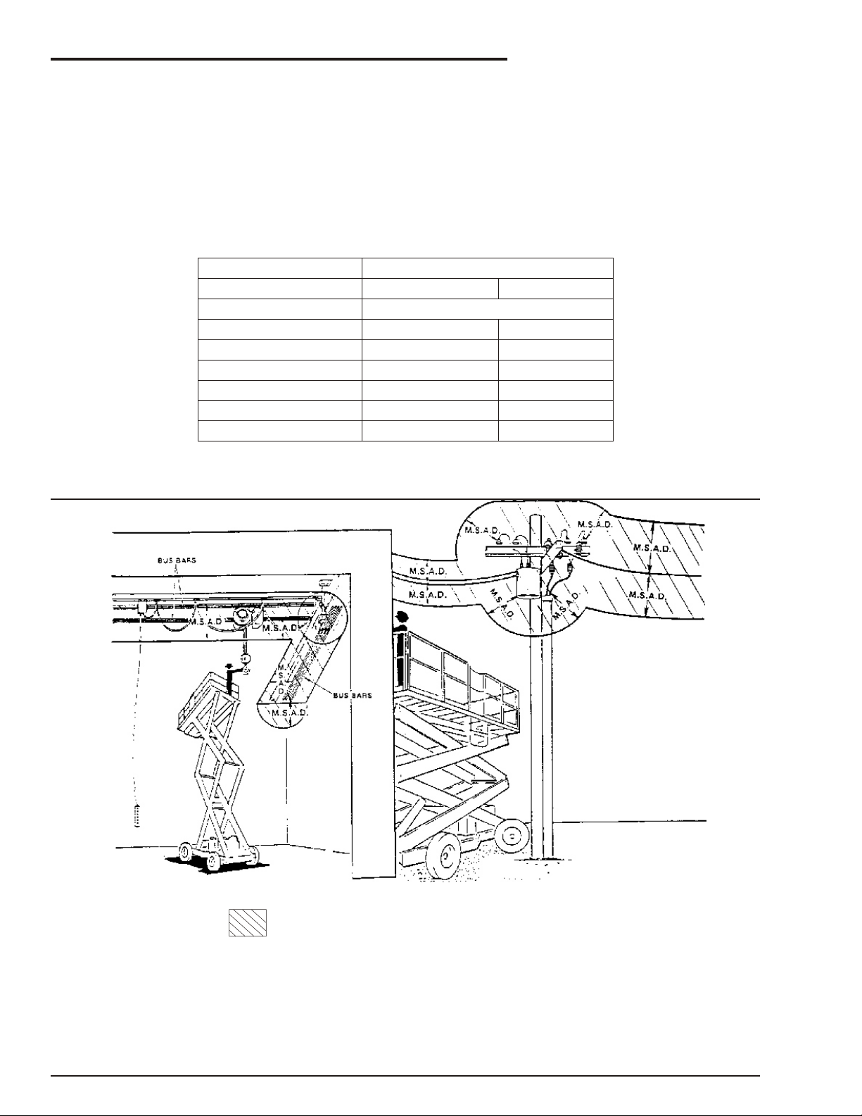
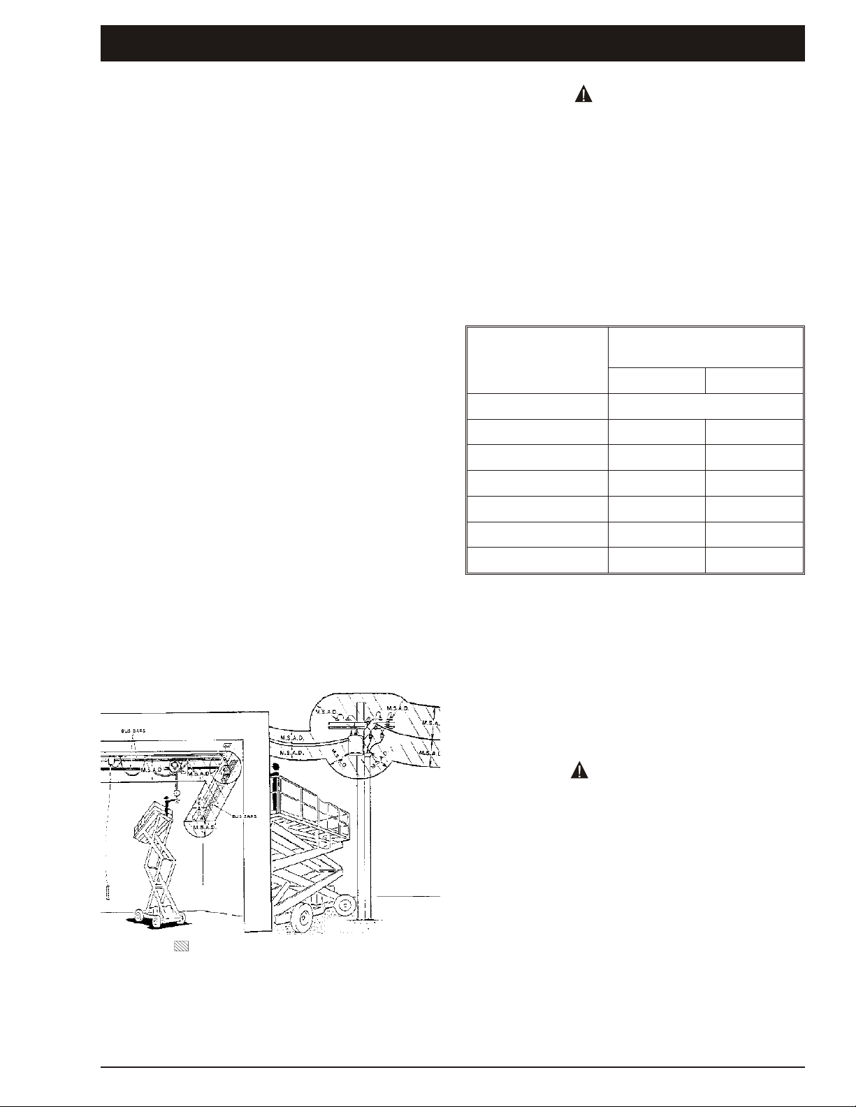
Minimum Safe Approach Distance
An SR is an all metal NOT ELECTRICALLY INSULATED, ae rial work plat form. DO NOT op er ate it near
ELECTRICAL con duc tors. Re gard all con duc tors as be ing en er gized. Use the ta ble and il lus tra tion be low
to de ter mine safe clear ance from elec tri cal con duc tors. (Ta ble 1 and Fig ure 3, be low, are from ANSI/SIA
A92.6–1990 Stan dard, re printed with per mis sion of Scaf fold In dus try As so ci a tion.)
q Table 1 - (M.S.A.D.)
Minimum Safe Approach Distance
to energized (exposed or insulated power lines)
Voltage range Minimum safe approach distance
(phase to phase)
0 to 300V
over 300v to 50kv
over 50kv to 200kv
over 200kv to 350kv
over 350kv to 500kv
over 500kv to 750kv
over 750kv to 1000kv
(Feet) (Meters)
Avoid contact
10
15
20
25
35
45
3.05
4.60
6.10
7.62
10.67
13.72
q Figure 3 - (M.S.A.D.)
page - ii Rev B SR3370 & SR2770 – 12696A
Page 5

Introduction
DANGER
WARNING
CAUTION
IMPORTANT
The most im por tant chap ter in this man ual is the
safety chap ter - Chap ter 1. Take time, now, to study
it closely.
The in for ma tion in Chap ter 1, might save your life,
pre vent se ri ous in jury, or dam age to prop erty or the
SR3370 / SR2770.
This in tro duc tion also con tains im por tant in for ma tion con cern ing the re spon si bil i ties of the owner of
the ma chine.
n
Standard SR3370 / SR2770
The stan dard SR3370 / SR2770 in cludes the fol low ing fea tures:
l
Fully proportional one handed joy stick
control
l
Reliable diesel engine
l
Large 1200mm multi position extension deck
l
35% gradeability
l
4 wheel drive
l
Hour meter
l
Temperature & ammeter gauges
l
Easy access side trays for engine &
hydraulics
l
Lockable hinged covers
l
Independently operated hydraulic stabilisers
with auto level
l
Swinging gate
l
Independent articulating rear axles
l
Forklift pockets
l
Lifting lugs and tie down rings
Ad di tional cop ies of this man ual may be or dered
from Snor kel. Sup ply the model and man ual part
num ber from the front cover to as sure that the cor rect man ual will be supplied.
All in for ma tion in this man ual is based on the lat est
prod uct in for ma tion at the time of pub li ca tion. Snor kel re serves the right to make prod uct changes at
any time with out obligation.
n
Photographs
Pho to graphs are taken to rep re sent the ma chine
and its com po nent parts as clearly as pos si ble.
How ever, there may be mi nor dif fer ences be tween
the pho to graphs and your ma chine. This rep re sents in di vid ual cus tomer pref er ences and Snor kel's on-go ing committment to prod uct
de vel op ment.
n
Safety Alerts
A safety alert sym bol is used through out this man ual to in di cate dan ger, warn ing and cau tion in struc tions. Fol low these in struc tions to re duce the
like li hood of per sonal in jury, prop erty dam age or
dam age to the machine.
The terms dan ger, warn ing, and cau tion in di cate
vary ing de grees of per sonal in jury or prop erty dam age that can re sult if the in struc tion is not followed.
Denotes an imminently hazardous situation
which, if not avoided, will result in death or
serious injury.
n
Options
The fol low ing op tions are avail able for the SR3370
/ SR2770:
Denotes a potentially hazardous situation
which, if not avoided, could result in death or
serious injury.
l
Flashing light
l
No stabilisers
l
Non-marking tyres
l
110/240V power to platform
l
RCD/ELCB Outlet
l
Alternative power options
m
Gasoline engine
m
LPG engine
m
Combination LPG/Gasoline engine
n
Operation Manual
This man ual pro vides in for ma tion for safe and
proper op er a tion of the ae rial plat form. Read and
un der stand the in for ma tion in this Op er a tor’s man -
Denotes a potentially hazardous situation
which, if not avoided, may result in minor or
moderate injury.
It may also be used to alert against unsafe
practices or action which may result in damage
to the SR.
Denotes important information pertaining to
settings, capacities, conditions, which could, if
ignored lead to machine damage or future
hazardous situations.
ual be fore op er at ing this ma chine on a job site.
SR3370 & SR2770 – 12696A Rev B page - iii
Page 6
Introduction
WARNING
IMPORTANT
IMPORTANT
It is also used to alert the reader to pay careful
attention to a particular passage of text in the
manual.
Notes
Notes are used to provide special information or
helpful hints to assist in aerial platform operation,
but do not indicate a hazardous situation.
n
Operation
The SR ae rial plat form has built in safety fea tures
and has been fac tory tested for com pli ance with
Snor kel spec i fi ca tions and in dus try stan dards.
How ever, any per son nel lift ing de vice can be po ten tially dan ger ous in the hands of un trained or
careless operators.
Train ing is vi tally im por tant and must be per formed
un der the di rec tion of a QUALIFIED per son. You
must dis play pro fi ciency in knowl edge and ac tual
op er a tion of the SR be fore us ing it on a job site.
Be fore op er a tion of the SR you must read and un der stand the op er at ing in struc tions in this man ual
as well as the de cals, warn ings, and in struc tions on
the ma chine it self.
Be fore op er at ing the SR you must be
AUTHORIZED by the per son in charge to do so
and the op er a tion of the SR must be within the
scope of the ma chine spec i fi ca tions.
Do not mod ify this ma chine with out writ ten ap proval from the En gi neer ing De part ment of Snor kel. Mod i fi ca tion may void the war ranty, ad versely
af fect sta bil ity, or af fect the op er a tional char ac ter is tics of the SR.
n
Responsibilities of parties
It is imperative that all owners and users of the SR
read, understand, and conform to all applicable
regulations. Ultimate compliance to OSHA
regulations is the responsibility of the user and their
employer.
It is imperative that all owners and users of the
SR read, understand, and conform to all
applicable regulations.
Ultimate compliance to OSHA regulations is the
responsibility of the user and their employer.
ANSI Standard A92.6 clearly identifies
requirements of all parties who might be
involved with Self-Propelled Elevating Work
Platforms.
AUSTRALIAN / NZ STANDARD 2550-10 also
identifies the requirements of all parties who
might be involved with Boom-Supported
Elevating Work Platforms.
The potential for an accident increases when
the aerial platform is operated by personnel who
are not trained and authorised. Death or serious
injury can result from such accidents.
Read and understand the information in this
manual and on the placards and decals on the
machine before operating the SR on the job site.
n
Maintenance
Ev ery per son who main tains, in spects, tests, or re pairs these ma chines, and ev ery per son su per vis ing any of these func tions, must be prop erly trained
and qual i fied to do so.
This Op er a tors Man ual pro vides a daily in spec tion
pro ce dure that will help you keep your SR in good
op er at ing con di tion.
Do not per form other main te nance un less you are a
trained me chanic, qual i fied to work on the SR. Call
qual i fied main te nance per son nel if you find prob lems or mal func tions.
Note - Standards
It is the responsibility of the owner to ensure that
the person operating the SR3370 / SR2770 is
provided with all the relevant information relating
to standards and codes of practice applicable in
their region.
q In summary
l
Only trained and authorised operators should
be permitted to operate the equipment.
l
All manufacturers operating instructions and
safety rules and all employers safety rules
and all OSHA and other government safety
rules should be strictly adhered to.
l
Repairs and adjustments should be made
only by qualified and trained maintenance
personnel.
l
No modification should be made to the
equipment without prior written consent of
the Snorkel Engineering Department.
l
Make a pre-start inspection of the SR at the
beginning of each shift. A malfunctioning
machine must not be used.
page - iv Rev B SR3370 & SR2770 – 12696A
Page 7

l
Make an inspection of the work place to
locate possible hazards before operating the
SR.
n
Additional information
For ad di tional in for ma tion, con tact your lo cal
dealer or Snor kel at:
Snor kel In ter na tional,
PO Box 1041
Levin 5510
New Zea land
Introduction
SR3370 & SR2770 – 12696A Rev B page - v
Page 8

Page 9

Table of Contents
Electrical Hazard
Electrical Hazard Warning ..................i
Minimum Safe Approach Distance ...........ii
Table 1 - (M.S.A.D.) .....................ii
Figure 3 - (M.S.A.D.) ....................ii
Introduction
Standard SR3370 / SR2770 ................iii
Options................................iii
Operation Manual........................iii
Photographs............................iii
Safety Alerts............................iii
Operation ..............................iv
Maintenance ...........................iv
Responsibilities of parties .................iv
Additional information .....................v
1. Safety
Safe Operation ........................1-1
Electrocution Hazards ...................1-1
Minimum safe approach distance .........1-1
Pre-start Inspection .....................1-1
Work Place Inspection and Practices .......1-1
Operation.............................1-2
Tipover and Falling Hazards ..............1-3
General Safety Precautions ..............1-3
Hydraulic System Precautions ............1-3
Fire Prevention ........................1-3
Engine and Fuel Handling Precautions......1-3
Batteries .............................1-4
Safety Decals and Placards ..............1-4
Safety Placards and Decals Location .......1-5
2. Safety Devices
Safety Device Information ................2-1
Emergency Stop Switches................2-1
At platform control box .................2-1
At ground control box ..................2-1
Alarms ...............................2-1
Level sensor .........................2-2
Lowering ............................2-2
High temperature .....................2-2
Low oil pressure ......................2-2
Drive (reverse) .......................2-2
Drive (forward) .......................2-2
Guardrails ............................2-2
Safety Prop ...........................2-2
Swinging Gate .........................2-3
Safety Control .........................2-3
Bubble Level ..........................2-3
Operator Horn ........................2-3
Stabilisers ............................2-3
RCD/ELCB AC Outlet (option) ............2-4
Flashing Light (option)...................2-4
Lanyard Anchor Points (option) ...........2-4
3. Specifications
Specifications .........................3-1
General Specifications, Standard Machine
SR3370 ..............................3-1
Recommended Hydraulic Oil..............3-1
General Specifications, Standard Machine
SR2770 ..............................3-2
Engine Oil Charts ......................3-3
Engine Data...........................3-3
DF752 ..............................3-3
D902 ...............................3-3
Machine Component Identification .........3-4
4. Gauges
Water................................4-1
Amps ................................4-1
Engine Oil ............................4-1
Hydraulic Oil Level .....................4-1
Hours................................4-2
Fuel Level (option)......................4-2
Bubble Level ..........................4-2
5. Automatic Shut-offs and Circuit Breakers
Automatic Shut-offs ....................5-1
Level sensor .........................5-1
Engine temperature ...................5-1
Engine oil pressure ....................5-1
Platform height vs. drive speed...........5-1
Dynamic brakes ......................5-1
Alternator not charging .................5-1
Stabilisers ...........................5-1
Circuit Breakers .......................5-2
Main breaker .........................5-2
RCD / ELCB outlet (option)..............5-2
6. Controls
Controls ..............................6-1
Hydraulic Compartment..................6-1
Ground Control Box.....................6-1
Platform Control Box ....................6-2
7. Daily Inspection and Maintenance
Daily Inspection and Maintenance Table.....7-1
Fuel Level ............................7-2
(LPG - Option) .......................7-2
Fuel Filter (diesel engines only) ...........7-2
Fuel Leaks............................7-2
Engine Oil ............................7-3
Engine Coolant ........................7-3
Radiator Cap ..........................7-3
SR3370 & SR2770 – 12696A
Page 10

Table of Contents
Swinging Gate ........................7-3
Wiring Harnesses and Connectors .........7-3
Battery Terminals.......................7-4
Battery Fluid Level......................7-4
Hydraulic Oil Tank ......................7-4
Hydraulic tank cap.....................7-4
Hydraulic oil level .....................7-4
Hydraulic Oil Leaks ....................7-4
Tires and Wheels.......................7-5
Bolts and Fasteners ....................7-5
Structural Damage & Welds ..............7-6
Guardrails ............................7-6
Bubble Level ..........................7-6
Guides, rollers, and slides................7-6
Charging System.......................7-7
Ground Controls .......................7-7
Flashing Light (Option) ..................7-7
Platform Controls.......................7-7
Emergency Lowering....................7-7
RCD / ELCB (Option) ...................7-8
Safety prop ...........................7-8
Lanyard Anchorages (Option) ............7-8
Non-Slip Tread Grip.....................7-8
Wrist Support..........................7-8
Placards and Decals ...................7-10
Standard placards and decals...........7-10
Inspection drawing ...................7-11
8. Operation
10. Stowing and Transporting
Stowing .............................10-1
Transporting .........................10-2
Trailering ...........................10-2
Securing to a Transport Vehicle .........10-2
Towing ............................10-3
Lifting / Lashing Down.................10-3
Pushing ...........................10-3
Winching Procedure ..................10-3
11. Options
RCD / ELCB Outlet ....................11-1
Flashing Light ........................11- 1
Lanyard Anchor Points .................11- 1
Electrical Outlet .......................11- 1
Non-Marking Tyres ....................11- 1
Alternative Power Options ...............11- 1
12. Fire Fighting and Chemical Containment
Hazardous Components ................12-1
Antifreeze (UN 1993) .................12-1
Battery, Lead/Acid (UN 2794) ...........12-1
Diesel Fuel (NA 1993).................12-1
Foam In Tires .......................12-2
Gasoline (UN 1203) ..................12-2
Hydraulic Oil (UN 1270) ...............12-3
Liquefied Petroleum Gas (UN 1075)......12-3
Motor Oil (UN 1270) ..................12-3
Operating Procedures ...................8-1
Control Stations ........................8-1
Emergency Stopping ....................8-1
Operation Considerations ................8-1
Fuel type .............................8-2
Operating From The Ground Control Box ...8-2
Raising the platform ...................8-3
Operating From The Platform Control Box ...8-4
Driving ..............................8-6
Raising the Platform ...................8-7
Stabilisers ............................8-7
Operating The Stabilisers Manually.........8-8
To set the stabilisers ...................8-8
To raise the stabilisers: ................8-8
Operating The Auto Level System .........8-9
Setting the stabilisers automatically .......8-9
Raising the stabilisers automatically.......8-9
Extending The Multi-Position Platform ......8-9
9. Emergency Operation
Emergency Operation Procedures .........9-1
Emergency Stop .......................9-1
Emergency Bleed-Down .................9-1
Pushing / Towing .......................9-2
13. Operator's Troubleshooting
Troubleshooting.......................13-1
Operator Troubleshooting Chart .........13-1
Appendix A. Glossary
page - viii SR3370 & SR2770 – 12696A
Page 11
n
Denotes prohibited zone
Caution:
- Diagrams shown are only for purposes of illustrating
M.S.A.D. Work positions, not all work positions.
DANGER
WARNING
Safe Operation
Knowl edge of the in for ma tion in this man ual, and
proper train ing, pro vide a ba sis for safely op er at ing
the SR3370 / SR2770. Know the lo ca tion of all the
con trols and how they op er ate to act quickly and re spon si bly in an emergency.
Safety de vices re duce the like li hood of an ac ci dent. Never dis able, mod ify, or ig nore any safety
de vice. Safety alerts in this man ual in di cate sit u a tions where ac ci dents may occur.
If any mal func tion, haz ard or po ten tially un safe
con di tion re lat ing to ca pac ity, in tended use, or safe
op er a tion is sus pected, stop the op er a tion of the
SR and seek assistance.
The op er a tor bears ul ti mate re spon si bil ity for fol low ing all man u fac tur ers in struc tions and warn ings, reg u la tions and safety rules of their em ployer
and/or any coun try or regional law.
1. Safety
The SR is not electrically insulated. Death or
serious injury can result from contact with, or
inadequate clearance from, an energised
conductor. Do not go closer than the minimum
safe approach distance as defined by ANSI.
ANSI pub li ca tions de fine min i mum dis tances that
must be ob served when work ing near bus bars and
energised power lines. Fig ure 1 and Ta ble 1 are re printed cour tesy of the Scaf fold in dus try As so ci a tion, ANSI/SIA A92.5.
Voltage Range
(Phase to Phase
0 to 300V
Minimum Safe Approach
Distance
Feet Metres
Avoid Contact
n
Electrocution Hazards
The SR is an all metal ae rial work plat form and is
not elec tri cally in su lated. Do not op er ate it near
elec tri cal con duc tors. Re gard all con duc tors as be ing en er gized. Do not op er ate out side dur ing a
thunderstorm.
q Minimum safe approach distance
Min i mum safe ap proach dis tances to energised
power lines and their as so ci ated parts must be ob served wile op er at ing the SR.
Over 300V to 50kV
Over 50kV to 200kV
Over 200kV to 350kV
Over 350kV to 500kV
Over 500kV to 750kV
Over 750kV to 1000kV
10 3.05
15 4.60
20 6.10
25 7.62
35 10.7
45 13.72
Table 1. - Minimum Safe Approach Distance
n
Pre-start Inspection
At the start of each work shift, the SR3370 /
SR2770 shall be given a vi sual in spec tion and
func tion test. See the Daily In spec tion and Main te nance chap ter , in this man ual for a list of items to
in spect and test.
DO NOT operate the SR3370 / SR2770 unless
you are trained and authorized, understand the
operation characteristics of the SR3370 /
SR2770, and have inspected and tested all
functions to be sure they are in proper working
order.
n
Work Place Inspection and Practices
Do not use the SR3370 / SR2770 as a ground for
weld ing. Ground to the work piece.
Be fore the SR3370 / SR2770 is used, and dur ing
use, check the area in which the SR3370 / SR2770
Figure 1. - Minimum Safe Approach Distance
SR3370 & SR2770 – 12696A Rev B page 1 - 1
is to be used for pos si ble haz ards such as, but not
lim ited to:
Page 12

1. Safety
DANGER
l
Drop-offs or holes.
l
Side slopes.
l
Bumps and floor obstructions.
l
Debris.
l
Overhead obstructions and electrical
conductors.
l
Hazardous locations.
l
Inadequate surface and support to withstand
all load forces imposed by the aerial platform
in all operating configurations.
l
Wind and weather conditions.
l
Presence of unauthorized persons.
l
Other possible unsafe conditions.
Se cure all ac ces so ries, con tain ers, tools, and
other ma te ri als in the plat form to pre vent them from
ac ci den tally fall ing or be ing kicked off the platform.
Al ways look in the di rec tion of travel. Drive with
care and at speeds com pat i ble with the work-place
con di tions. Use cau tion when driv ing over rough
ground, on slopes, and when turning.
Do not en gage in any form of horse play or stunt
driv ing while op er at ing the SR3370 / SR2770.
Do not per mit rid ers on the ma chine any place other
than on the plat form.
Re move all loose ob jects stored in or on the ma chine, par tic u larly in the plat form. Re move all ob jects which do not be long in or on the machine.
Be fore the SR3370 / SR2770 is used, de ter mine
the haz ard clas si fi ca tion of any par tic u lar at mo sphere or lo ca tion ac cord ing to ANSI/NFPA
505-1987.
Any SR3370 / SR2770 op er ated in a haz ard ous lo ca tion must be ap proved and of the type re quired
by ANSI/NFPA 505-1987.
While op er at ing the SR a rec om mended safety
prac tice is to have trained and qual i fied per son nel
in the im me di ate work area of the SR3370 /
SR2770 to:
l
Help in case of an emergency.
l
Operate emergency controls as required.
l
Watch for loss of control by platform
operator.
l
Warn the operator of any obstructions or
hazards that may not be obvious to them.
l
Watch for soft terrain, sloping surfaces,
drop-offs, etc., where stability could be
jeopardized.
l
Watch for bystanders and never allow
anyone to be under, or to reach through the
booms while operating the aerial platform.
Never steady the plat form by po si tion ing it against
an other plat form.
Do not op er ate an SR3370 / SR2770 that is dam aged or not func tion ing prop erly. Do not use the SR
un til the ma chine has been re paired by a qual i fied
main te nance person.
Do not op er ate a SR3370 / SR2770 that does not
have all its de cals and plac ards at tached and leg i ble.
Watch for by stand ers and never al low any one to be
un der, or to reach through, the ma chine and its
equip ment while op er at ing.
Use the rec om mended trans port de vice when
load ing the ma chine.
n
Operation
If you en coun ter any sus pected mal func tion of the
ae rial plat form, or any haz ard or po ten tially un safe
con di tion re lat ing to ca pac ity, in tended use, or safe
op er a tion, cease op er a tion im me di ately and seek
as sis tance from management.
Use three points of sup port when get ting on or off
the plat form (two hands and one foot or a sim i lar set
of points). Keep the plat form clean.
Main tain a firm foot ing on the plat form floor. Op er ate the con trols slowly and de lib er ately to avoid
Pinch points may exist between moving
components. Death or serious injury can result
from becoming trapped between components,
buildings, structures, or other obstacles. Make
sure there is sufficient clearance around the
jerky and er ratic op er a tion. Al ways stop the con trols in neu tral be fore go ing in the op po site
direction.
Do not dis mount while the plat form is in mo tion or
jump off the ma chine.
machine before moving the chassis, booms, or
platform. Allow sufficient room and time to stop
movement to avoid contact with structures or
other hazards.
Keep ground per son nel from un der the plat form
when the plat form is raised.
page 1 - 2 Rev B SR3370 & SR2770 – 12696A
Do not start un til all per son nel are clearly away
from the ma chine.
Never cover the floor grat ing or oth er wise ob struct
your view be low. Make sure the area be low the
plat form is free of per son nel be fore low er ing.
Page 13

1. Safety
DANGER
DANGER
DANGER
n
Tipover and Falling Hazards
Op er ate the SR only on a firm, flat, level sur face ca pa ble of with stand ing all load forces im posed by
the SR3370 / SR2770 in all op er at ing con di tions.
The SR can tip over if it becomes unstable.
Death or serious injury can result from a tip-over
accident. Do not drive or position the SR
platform for elevated use near any drop-off,
hole, slope, soft or uneven ground, or other
tip-over hazard.
Do not op er ate the SR3370 / SR2770 from a po si tion on trucks, trail ers, rail way cars, float ing ves sels, scaf folds, or sim i lar equip ment un less the
ap pli ca tion is ap proved in writ ing by Snorkel.
Care shall be taken to pre vent rope, elec tric cords,
and hoses, etc., from be com ing en tan gled in the
ae rial plat form. If the plat form or el e vat ing as sem bly be comes caught, snagged, or oth er wise pre vented from nor mal mo tion by an ad ja cent
struc ture or other ob sta cle such that con trol re ver sal does not free the plat form, re move all per son nel
from the plat form be fore at tempts are made to free
the platform using ground controls.
Do not climb on the guard rails or use lad ders,
planks, or other de vices to ex tend or in crease your
work po si tion from the plat form.
Do not use the SR as a crane, hoist, or jack,or for
any other pur pose other than to po si tion per son nel,
their tools, and ma te ri als.
Do not op er ate the SR3370 / SR2770 in winds, or
wind gusts, of 28 mph, 45kph 12.5 m/s) or more
and do not add any thing to the SR3370 / SR2770
that will in crease the wind load ing (ban ners, flags,
etc.).
n
General Safety Precautions
Do not mod ify the SR3370 / SR2770 in any way.
When parts or com po nents are re placed, they shall
be iden ti cal or equiv a lent to orig i nal Snor kel parts
or com po nents.
Do not over ride any of the safety fea tures of the
SR3370 / SR2770.
n
Hydraulic System Precautions
The hy drau lic sys tem con tains hoses with hy drau lic fluid un der pres sure.
Un der nor mal work ing con di tions it is best not to
trans fer from the plat form to an other struc ture or
vice versa, un less that is the saf est way to do the
job. Each sit u a tion must be judged sep a rately tak ing the work en vi ron ment into ac count. The fol low ing guidelines apply:
1. Where possible, place the work platform over
a roof or walking structure to do the transfer.
2. Transfer your anchorage from one structure
to another before you step across.
3. Remember, you might be departing the work
platform to a structure where fall arrest is
required.
4. Do not climb over or through the guardrails.
Use the platform entrance.
All plat form oc cu pants MUST wear and use fall re straint. At tach fall re straints to the plat form lan yard
an chor points.
Do not ex ceed the un re stricted plat form ca pac ity
as in di cated on the ca pac ity plac ard at the en trance to the plat form. Do not carry loads from any
point out side of the platform.
Hydraulic fluid escaping under pressure can
have enough force to inject fluid into the flesh.
Serious infection or reaction can result if
medical treatment is not given immediately. In
case of injury by escaping hydraulic fluid, seek
medical attention at once.
DO NOT place your hand or any part of your body in
front of es cap ing hy drau lic fluid. Use a piece of
card board or wood to search for hy drau lic leaks.
Do not at tempt re pairs to hy drau lic sys tems un less
you are trained. Re fer to ex pe ri enced re pair per son nel for help.
n
Fire Prevention
Never op er ate your SR near a flame or spark. Hy drau lic oil and gas o line are flam ma ble and can ex plode.
n
Engine and Fuel Handling Precautions
Make sure that all pro tec tive guards, cowl ings, and
doors are in place and se cure. Be sure the guard rail sys tem, in clud ing the gate, is in place and se cure.
SR3370 & SR2770 – 12696A Rev B page 1 - 3
Engine exhaust contains carbon monoxide, a
poisonous gas that is invisible and odorless.
Breathing engine exhaust fumes can cause
death or serious illness. Do not run the engine in
Page 14

1. Safety
WARNING
CAUTION
WARNING
CAUTION
an enclosed area or indoors without adequate
ventilation.
Only re fuel your SR out doors in a clear area void of
gas fumes or spilled gas.
Never re move the fuel cap or re fuel a gas o line en gine while the en gine is run ning or hot. ALWAYS al low the en gine to cool be fore re fu el ing. Never al low
fuel to spill on hot ma chine components.
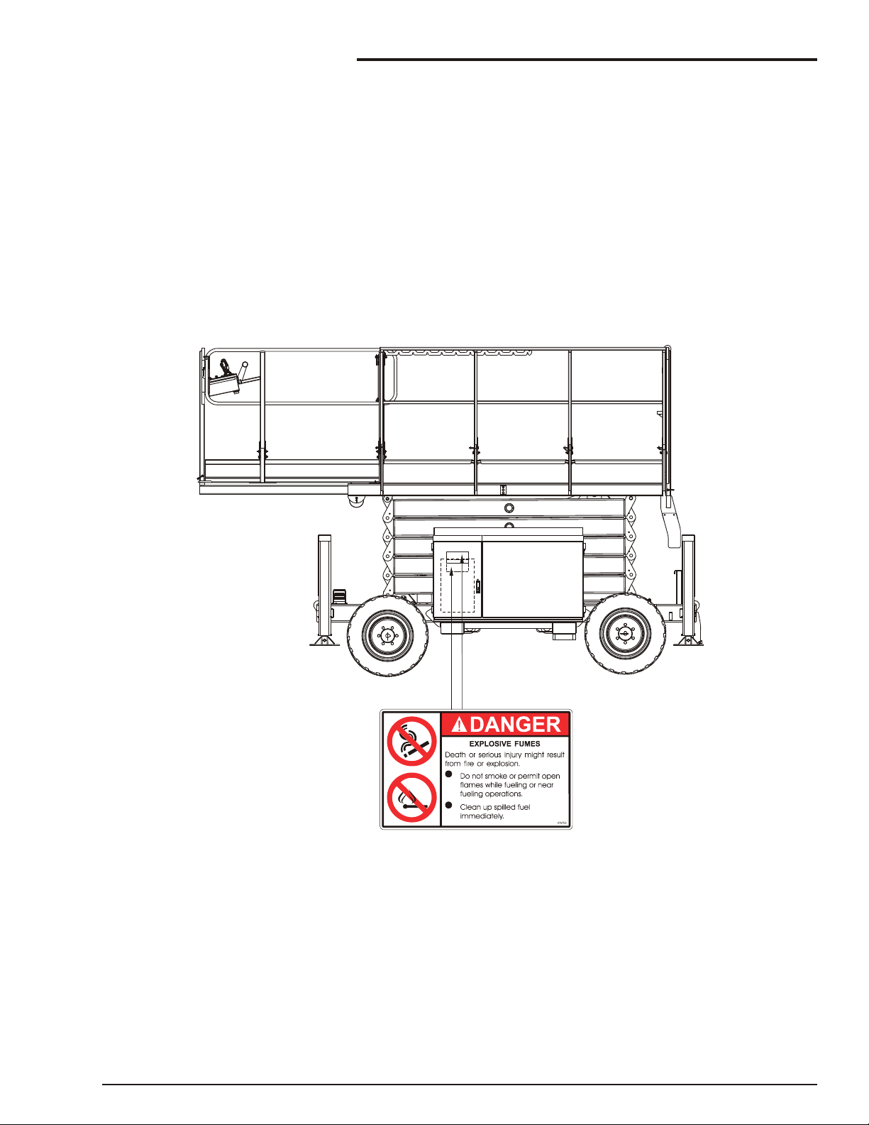
DO NOT smoke or permit open flames while
fueling or near fueling operations.
Main tain con trol of the fuel filler noz zle when fill ing
the tank.
ENSURE you use an approved fuel container
with appropriate fuel filler nozzle
Do not fill the fuel tank to ca pac ity. Al low room for
ex pan sion.
If gas o line is spilled, clean up spilled fuel im me di ately, push/tow the SR away from the area of the
spill and avoid cre at ing any source of ig ni tion un til
the spilled fuel has evap o rated.
Bat ter ies con tain sul fu ric acid that can dam age
your eyes or skin on con tact. Wear a face shield,
rub ber gloves, and pro tec tive cloth ing when work ing around bat ter ies. If acid con tacts your eyes,
flush im me di ately with clear wa ter and get med i cal
at ten tion. If acid con tacts your skin, wash off im me di ately with clear water.
n
Safety Decals and Placards
There are sev eral safety de cals and plac ards on
the SR3370 / SR2770. Their lo ca tions and de scrip tions are shown in this sec tion. Take time to study
them.
Be sure that all the safety decals and placards
on the SR3370 / SR2770 are legible. Clean or
replace them if you cannot read the words or see
the pictures. Clean with soap & water and a soft
cloth. Do not use solvents.
You MUST replace a decal or placard if it is
damaged, missing, or cannot be read. If it is on a
part that is replaced, make sure a new decal or
placard is installed on the replaced part. See
your Snorkel dealer for new decals and
placards.
Tighten the fuel tank cap se curely. If the fuel cap is
lost, re place it with an ap proved cap from Snor kel.
Use of a non-ap proved cap with out proper vent ing
may re sult in pres sur iza tion of the tank.
Never use fuel for clean ing pur poses.
For die sel en gines, use the cor rect fuel grade for
the op er at ing sea son.
n
Batteries
Charge bat ter ies in a well ven ti lated area free of
flame, sparks, or other haz ards that might cause
fire or ex plo sion.
Batteries give off hydrogen and oxygen that can
combine explosively. Death or serious injury can
result from a chemical explosion. Do not smoke
or permit open flames or sparks when checking
batteries.
Battery acid can damage the skin and eyes.
Serious infection or reaction can result if
medical treatment is not given immediately.
Wear face and eye protection when working
near batteries.
page 1 - 4 Rev B SR3370 & SR2770 – 12696A
Page 15
n
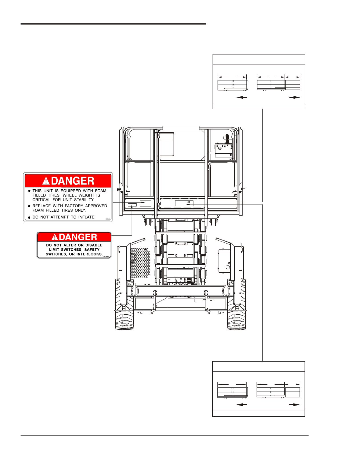
LEFT HAND SIDE OF THE SR
On Fuel Tank Inside Cabinet &
Outside Of Cabinet Door
Safety Placards and Decals Location
1. Safety
SR3370 & SR2770 – 12696A Rev B page 1 - 5
Page 16
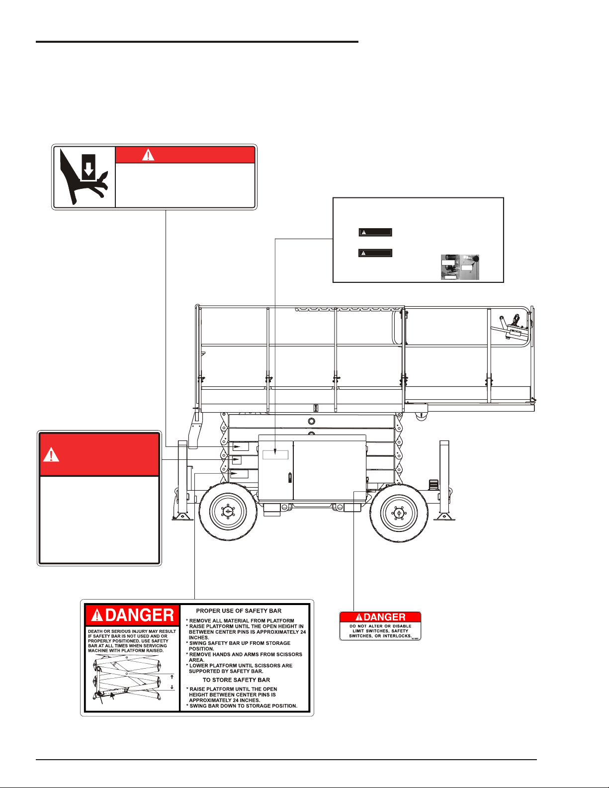
1. Safety
RIGHT-HAND SIDE OF SR
STORAGE POSITION
PROPER POSITION FOR USE
SAFETY BAR
24”
YOU MUST NOT OPERATE THIS DEVICE UNLESS:
AN UNTRAINED OPERATOR SUBJECTS HIMSELF AND OTHERS TO
DEATH OR SERIOUS INJURY.
0323897
1.
2.
YOU HAVE BEEN TRAINED IN THE SAFE OPERATION OF THIS
DEVICE AND HHHH
YOU KNOW AND FOLLOW THE SAFETY AND OPERATING
RECOMMENDATIONS CONTAINED IN THE MANUFACTURER'S
MANUALS, YOUR EMPLOYER'S WORK RULES, AND APPLICABLE GOVERNMENTAL REGULATIONS. HHHHHHHH
DANGER
DANGER
300700
SHEARING HAZARD/CRUSHING HAZARD
D EA TH OR SERI OUS I NJURY M IGHT RESULT FROM
HAVI NG BODY PARTS SHEARED OR CRUSHE D AS THE
PLATFORM DESCENDS. K EEP AWAY FROM CLOSING
SCISSOR ARM S AND KEEP OUT FROM UNDER THE
PLATFORM AS THE PLATFORM COMES DOWN.
EMERGENCY OPERATION
1. EMERGENCY LOWERING
In the event of total power failure pull the emergency lowering handle
mounted at the front of the chassis until the platform starts to descend.
Once the platform is lowered the handle can be released.
In order to push or tow the SR the following steps MUST be
taken.
A runaway SR can cause Death or serious injury. Do not proceed
unless the SR is on a level surface or is attached to an object that
can hold the SR on a slope.
The SR Drive motors will be ruined if the SR is pushed or towed
faster than 3.2 kph (2 mph).
2. TOWING OR PUSHING THE SR
Freewheel the Drive Motors
DANGER
CAUTION
Turn the FREEWHEEL knob [A] Counterclockwise fully.
Release the Brakes
Pump the hand pump [B] 5 to 10 times or until the Brakes are
released.
To re-set the Brakes pull knob [C] until it is fully open.
To re-set the Drive Motors turn the FREEWHEEL knob [A]
clockwise until it is fully closed.
After the SR has been pushed or towed the Brakes and the
Drive Motors MUST be re-set.
12816
Freewheel
Valve
Pull To Reset
Brakes
Hand Pump
A
B
C
page 1 - 6 Rev B SR3370 & SR2770 – 12696A
Page 17
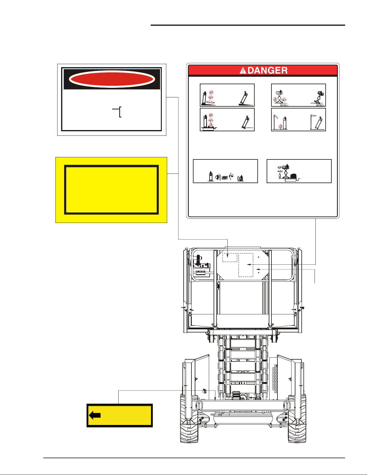
FRONT END OF SR
DEATH OR SERIOUS INJURY CAN RESULT FROM TIPPING OVER.
TO KEEP FROM TIPPING THIS MACHINE OVER FOLLOW THESE RULES.
OTHER ACTIONS CAN ALSO CAUSE THIS MACHINE TO TIP OVER
NOTE: STUDY THE OPERATOR'S MANUAL BEFORE OPERATING THIS MACHINE.
12574
DO NOT override safety devices.
DO NOT overload the machine.
DO NOT stand or sit on guardrails.
DO NOT attach ropes or chains to guardrails.
DO NOT carry loads outside the railing or use
as a crane.
DO NOT use this machine without the railings and the
entry gate in place. You could
fall out and hurt or kill yourself.
DO NOT use this machine if it is not operating correctly,
or if any part of it is damaged,
worn, or missing. An accident
could cause injury or death.
DO NOT let an untrained or unauthorized person use this machine.
When you leave the machine unattended,
remove the key, or turn off the battery
switch on the base of the machine and lock
the battery switch in the off position.
DO NOT replace components critical to machine stability, such as
batteries and wheel equipment, with lighter
weight or non-factory approved substitutes.
DO NOT ride platform while machine is on a truck, fork
lift or other device.
DO NOT use ladder, scaffold, or other means to
increase size or platform height.
DO NOT use with improperly inflated or damaged tires
or wheels.
DO NOT RAISE OR DRIVE AN ELEVATED
PLATFORM ON
SOFT OR UNEVEN
SURFACES
DO NOT RAISE OR DRIVE AN ELEVATED
PLATFORM ON A
SLOPE
GO NO CLOSER THAN 4 feet (1.2m)
to ANY DROP OFF
OR HOLE
4 FT/1.2M
OK
1.
3.2.
TWO-TONE ALARM MEANS TIPOVER DANGER!
LOWER PLATFORM IMMEDIATELY
TO AVOID
TIPOVER HAZARDS
USE ON
FLAT, LEVEL, AND
SOLID SURFACES
ONLY
OK
DO NOT RAISE A PLATFORM
IN WIND ABOVE 28 MPH (12.5 M/S)
4 FT/1.2M
DANGER
BEWARE OF ELECTRICAL HAZARDS
REGULATION 133A OF THE
CONSTRUCTION SAFETY ACT 1912 REQUIRES
(a) Minimum approach of an appliance
(b) Inspection of the work site for
(c) Constant vigilance and an observer required
to live electrical apparatus.
electrical hazards before
commencing to use the appliance.
whilst working or travelling the appliance
in the vicinity of live electrical apparatus.
3m. for voltages up to 132,000
6m. for voltages above 132,000
and up to 330,000
8m. for voltages above 330,000
WARNING
KEEP LINESCLEAR POWEROF
Unless the Electrical Supply Authority has advised
in writing otherwise;
the clearance between any live overhead
power line and any part of this machine or
load carried is required by law to be
AT LEAST 4 METRES
This is a requirement of regulation 93 of the
Electrical Supply Regulations 1984
in the interests of safe working.
EMERGENCY BLEED
DOWN VALVE
12753
Australia Only
New Zealand Only
ALL DECALS ON
REVERSE SIDE
OF PANEL
On Top Of Chassis Member
1. Safety
SR3370 & SR2770 – 12696A Rev B page 1 - 7
Page 18
1. Safety
REAR END OF SR
SR3370 PLATFORM RATINGS
UNIFORMLY DISTRIBUTED
RATED NUMBER OF OCCUPANTS: 2 PERSONS
12699
450kg
RATED WORK LOAD
RATED WORK LOAD
MAIN
DECK
EXTENSION
DECK
MAIN
DECK
990lb
120kg
264lb
330kg
726lb
EXTENSION DECK RETRACTED
EXTENSION DECK EXTENDED
SR2770 PLATFORM RATINGS
UNIFORMLY DISTRIBUTED
RATED NUMBER OF OCCUPANTS: 5 PERSONS
11346-1
580kg
RATED WORK LOAD
RATED WORK LOAD
MAIN
DECK
EXTENSION
DECK
MAIN
DECK
1280lb
120kg
264lb
460kg
1015lb
EXTENSION DECK RETRACTED
EXTENSION DECK EXTENDED
SR3370
SR2770
page 1 - 8 Rev B SR3370 & SR2770 – 12696A
Page 19
2. Safety Devices
WARNING
n
Safety Device Information
For emer gency op er a tion con trols and pro ce dures
see the Emer gency Op er a tion chap ter 9, in this
manual.
The de vices listed in this chap ter are safety de vices.
They are on an SR to in crease safety in the work
place for both the op er a tor and other peo ple near
the ma chine.
Do not by-pass, disable, modify, or ignore any of
these devices. Check them carefully at the start
of each work shift to see that they are in working
order (see Daily Inspection & Maintenance
chapter 7). If any is found to be defective,
remove the SR from service immediately until a
qualified service technician can make repairs.
n
Emergency Stop Switches
q At platform control box
q At ground control box
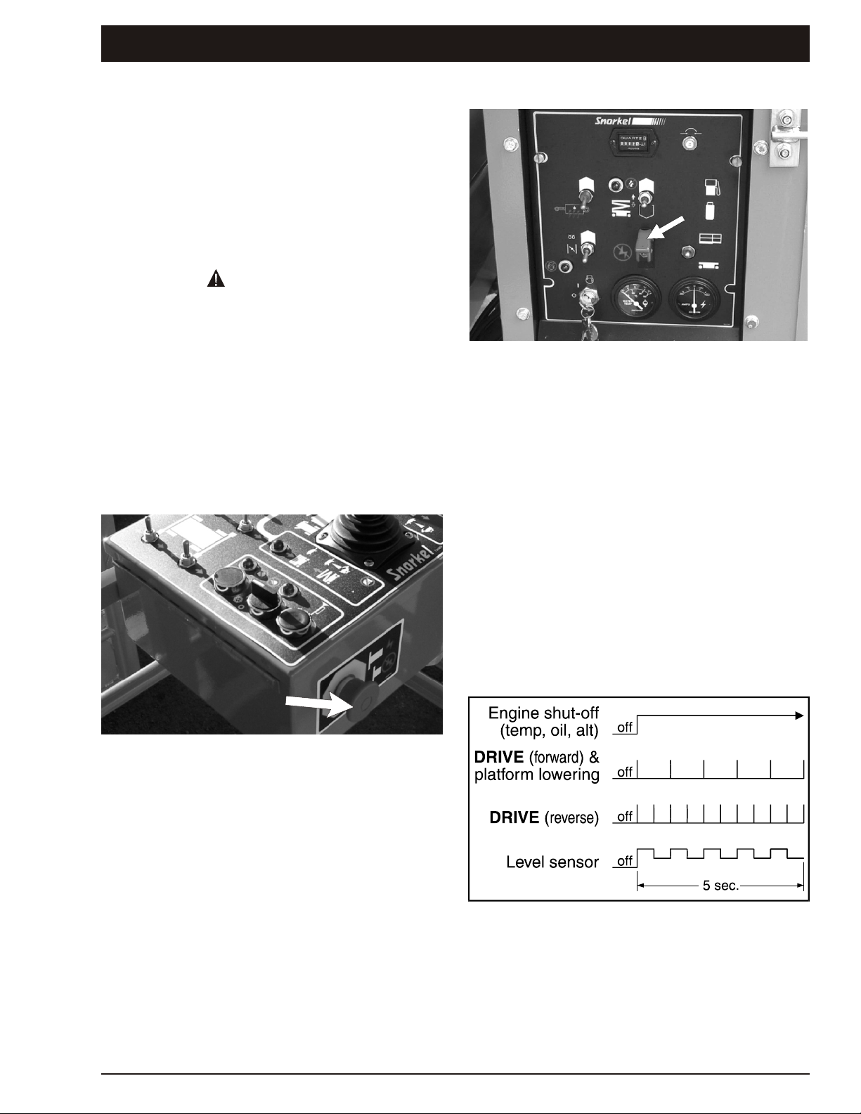
Figure 2.2 - Ground Control Box Emergency Stop
Switch
Press the red EMERGENCY STOP switch cover
down, at any time, un der any con di tions, and the
en tire ma chine stops, the en gine turns off, and
noth ing moves. the EMERGENCY STOP switch
must be up for any thing on the SR to work.
n
Alarms
There are two alarms on an SR. One is lo cated in
the plat form con trol box, the other is lo cated in the
ground con trol box.
Figure 2.1 - Platform Control Box Emergency
Stop Switch
Press the large red EMERGENCY STOP but ton in
and the en tire ma chine stops, the en gine turns off,
and noth ing moves. This switch must be out (on) to
con trol the SR from the plat form (pull the switch
and it will pop out).
The alarms are con nected in par al lel, they both
emit the same pat tern of sound at the same time.
The dif fer ent alarm sound pat terns are shown in
the ta ble im me di ately be low and dis cussed be low
the table.
Figure 2.3 - Alarm Sound Patterns
The high-tem per a ture, low oil-pres sure, and al ter na tor not-charg ing alarms are each a con tin u ous
tone.
SR3370 & SR2770 – 12696A Rev B page 2 - 1
Page 20
2. Safety Devices
The DRIVE (for ward) and the plat form-low er ing
alarms beep at one beep per sec ond. DRIVE (re verse) beeps at two beeps per sec ond. The level
sen sor alarm is a high-low war bling sound.
q Level sensor
The level sen sor alarm warns the SR op er a tor that
the SR is not level. When you hear this alarm, im me di ately lower the plat form com pletely down.
When the plat form is com pletely down, de ter mine
and cor rect the cause of the tilt be fore rais ing the
plat form again.
NOTE
While the alarm is sounding it is not possible to
drive the SR nor raise the platform
q Lowering
The low er ing alarm warns peo ple near an SR that
the plat form is com ing down and the scis sor arm
as sem bly is clos ing.
q High temperature
The high-tem per a ture alarm warns you that the en gine is over heat ing. When the alarm sounds you
should im me di ately lower the plat form com pletely
down then turn the en gine off un til the con di tion that
caused the over heat ing has been cor rected. (See
Au to matic Shut-Offs & Cir cuit Break ers chap ter 5
for more information.)
n
Guardrails
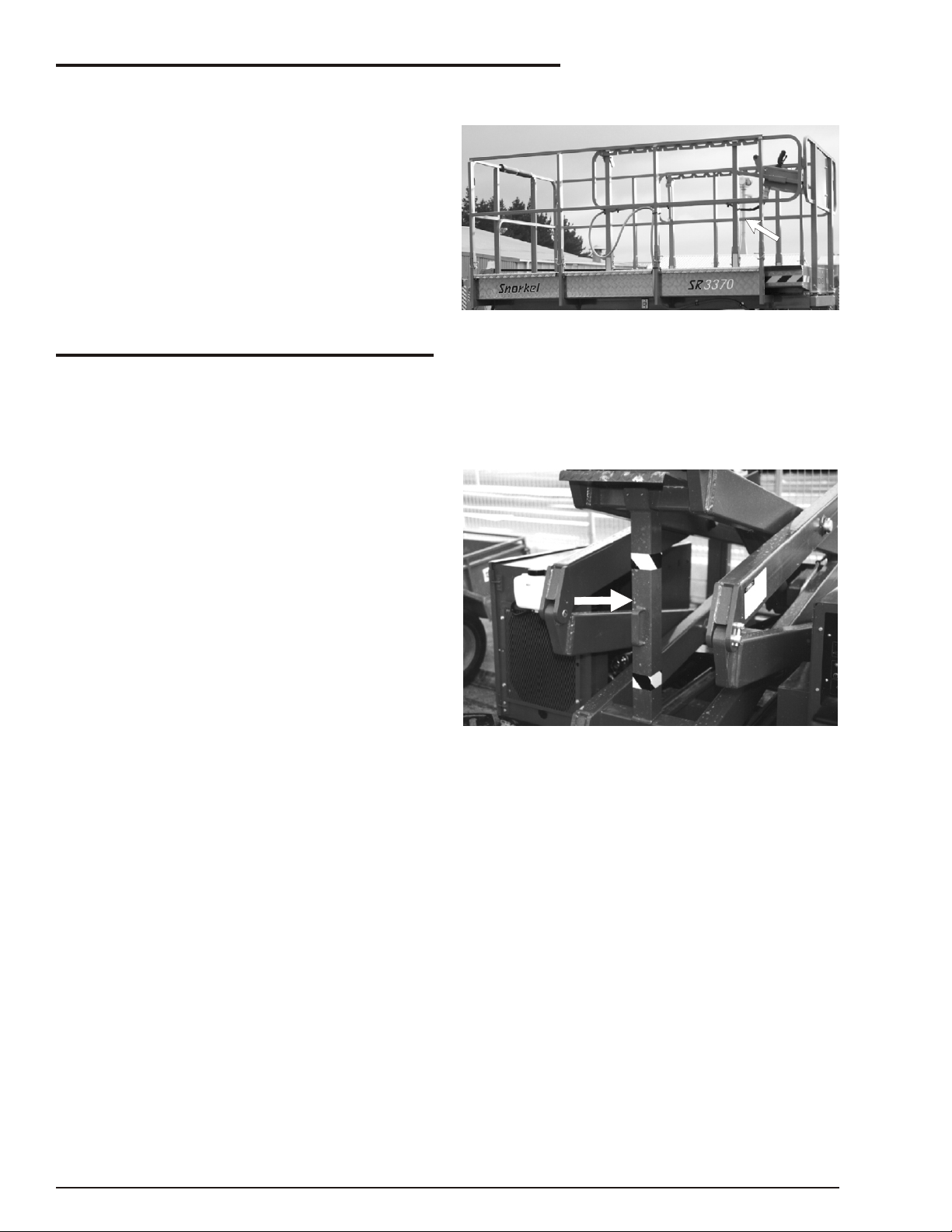
Figure 2.4 - Guardrails
The guard rails help pro tect you from fall ing off the
plat form. Be sure the guard rails are prop erly in stalled and that the gate is in place.
n
Safety Prop
q Low oil pressure
The low pres sure alarm warns you that the en gine
oil pres sure is near the lower limit for safe op er a tion
of the en gine. When the alarm sounds you should
im me di ately lower the plat form com pletely down
then turn the en gine off un til the con di tion that
caused the low oil pres sure has been cor rected.
(See Au to matic Shut-Offs & Cir cuit Break ers chap ter 5 for more information.)
q Drive (reverse)
The DRIVE (re verse) alarm alerts peo ple that the
SR is trav el ing back ward along the ground. This
alarm beeps twice as fast as the DRIVE (for ward)
alarm.
q Drive (forward)
The DRIVE (for ward) alarm alerts peo ple that the
SR is trav el ing for ward along the ground. This
alarm beeps half as fast as the DRIVE (re verse)
alarm.
Figure 2.5 - Safety Prop
Al ways raise the safety prop then lower the scis sor-arm as sem bly onto the safety prop be fore
reach ing into the scis sor-arm as sem bly for any
reason.
page 2 - 2 Rev B SR3370 & SR2770 – 12696A
Page 21
2. Safety Devices
n
Swinging Gate
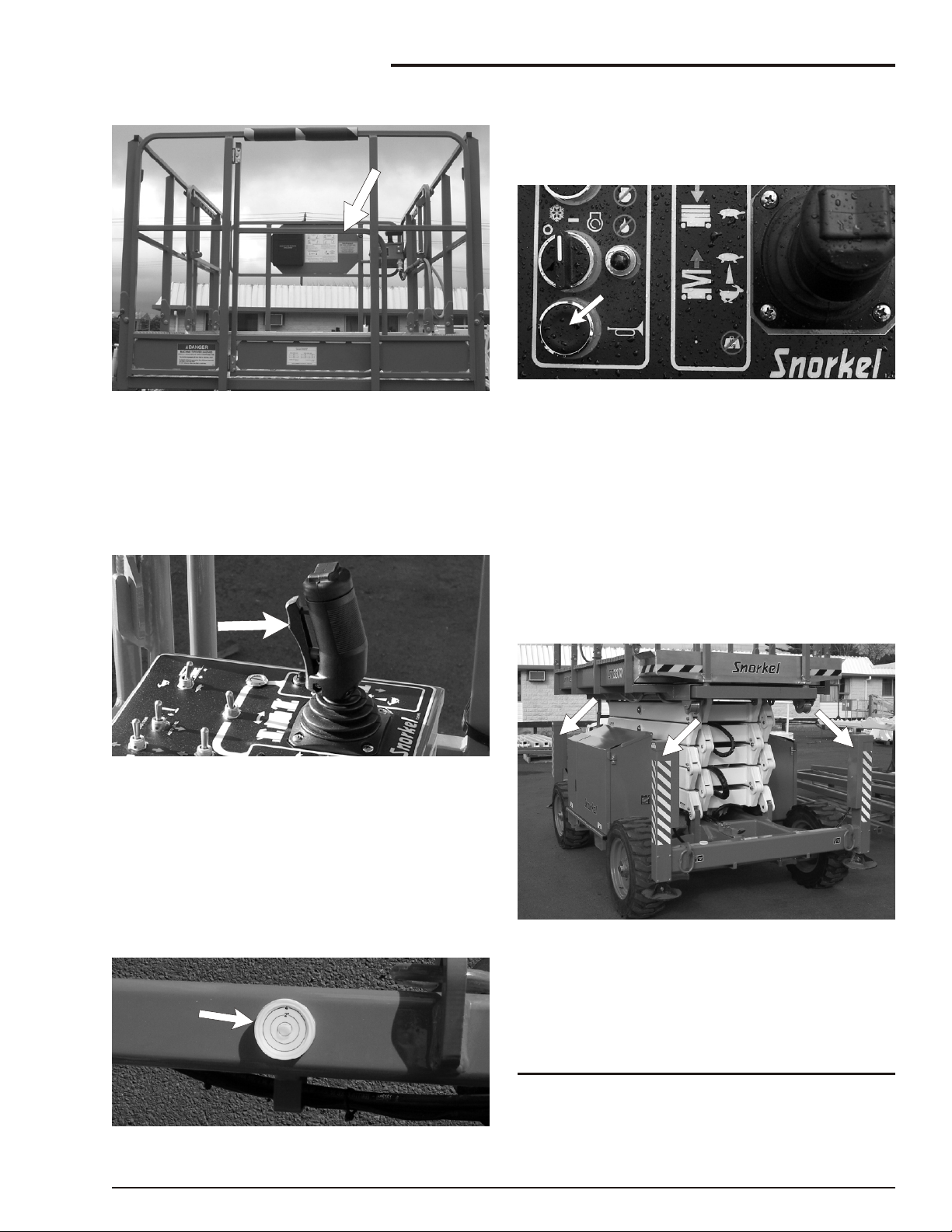
Figure 2.6 - Swinging Gate
The swing ing gate should be closed at all times ex cept when some one is en ter ing or leav ing the plat form.
n
Safety Control
See the Gauges chap ter 4 for a dis cus sion of the
bub ble level.
n
Operator Horn
Figure 2.9 - Operator Horn
The op er a tor horn is used pri mar ily to get the at ten tion of peo ple on the ground when you are work ing
aloft. For the horn to work the fol low ing switches,
on the ground con trol box, must be set as in di cated:
MAIN POWER........................ON
EMERGENCY STOP..............ON (up)
SELECTOR............................PLATFORM
Figure 2.7 - Joystick Safety Control
The safety con trol must be squeezed and held to
ac ti vate the joy stick. The safety con trol pre vents
the joy stick from mov ing the plat form if some thing
ac ci den tally pushes the joy stick. Do not dis able the
safety con trol in any way.
n
Bubble Level
Figure 2.8 - Bubble Level
n
Stabilisers
Figure 2.10 - Stabilisers
The sta bi liser con trols are on the up per left side of
the plat form con trol box. The sta bi lis ers are used to
level the SR (for com plete sta bi liser op er at ing pro ce dures see the Op er a tion chapter 8).
NOTE
The SR must be on a firm surface capable of
withstanding all load forces imposed by the aerial
platform in all operation conditions before the
stabilisers are used.
SR3370 & SR2770 – 12696A Rev B page 2 - 3
Page 22
2. Safety Devices
RCD
Power Input
Connector
Power Outlet
At Platform
n
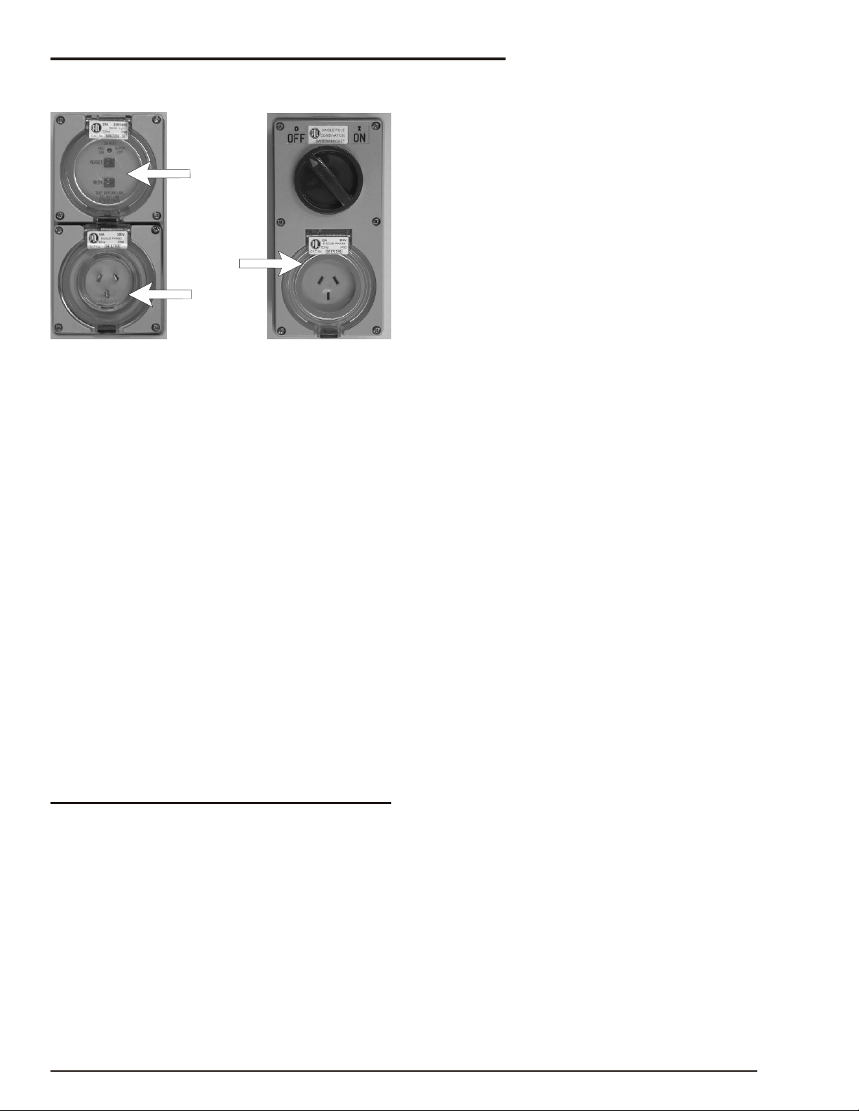
RCD/ELCB AC Outlet (option)
Figure 2.11 - RCD/ELCB AC Outlet
The RCD (Re sid ual Cur rent De vice) is lo cated at
the ground and will pro tect against short cir cuits to
earth. When there is a short cir cuit the RCD will
shut down the 230v AC power to the plat form out let. To re set the out let dis con nect the power tool
lead from the plat form box and re set the RCD at the
ground. If the prob lem per sists call a trained ser vice technician.
n
Flashing Light (option)
The flash ing light alerts peo ple that the SR is pres ent and that the SR is mov ing. The light flashes at
about one flash per sec ond any time the SR en gine
is run ning. There is no ON/OFF switch for the flash ing light, it can not be turned off while the SR is run ning.
n
Lanyard Anchor Points (option)
There are four an chors on the floor of the plat form,
one at the front of the roll-out deck, one at the back
of the plat form, and one on each side of the plat form.
NOTE
These anchors are not for lifting or tying down
the machine.
You should at tach your fall pro tec tion to the an chors if work rules re quire it.
page 2 - 4 Rev B SR3370 & SR2770 – 12696A
Page 23

3. Specifications
n
Specifications
The SR3370 / SR2770 se ries ma chines are scis sor-sup ported el e vat ing work plat forms built to con form to
the fol low ing stan dards.
OSHA Para graph 1910.67 Ti tle 29, C.F.R., Ve hi cle-Mounted El e vat ing and Ro tat ing Work Plat forms - La bour.OSHA Para graph 1926.556 Ti tle 29, C.F.R., Ae rial Lifts - Con struc tion.Aus tra lian Stan dard
AS1418-10(Int) 2004 El e vat ing Work Platforms.
NOTE:
For further details regarding lubricants, maintenance schedules and service please refer to the
Maintenance and Repair Parts Manual for this machine.
n
General Specifications, Standard Machine SR3370
SPECIFICATIONS SR3370
Nominal working height
Roll out deck size
Drive speed (below 2.4m)
Drive speed (above 2.4m)
Safe working load - Main deck
(Roll out deck not extended)
Safe working load - Main deck
Roll out deck extended - Roll out
deck
Platform size
Stowed height
Stowed height (hand rails folded down)
Overall length
Overall width
Gradeability
Lift time
12.12m 39' 2”
1200mm 48”
0 to 4.5kph 0 to 2.8mph
0 to 0.35kph 0 to 0.22mph
450kg 990lbs
330kg
120kg
2.73 x 1.65m 8’ 11” x 5’ 5”
2.7m 8' 10"
2.0m 6' 6"
3.36m 11’ 0”
1.77m 5' 9"
35%
50 seconds
726lbs
264lbs
Turning radius (inner)
Turning radius (outer)
Maximum wind speed (12.5m/s)
Insulation rating
Tyres - Poly filled loader lug
Overall weight
Ground clearance
Maximum sound level at platform
n
Recommended Hydraulic Oil
Shell Tellus 32 or Castrol AWS 32 or sim i lar.
SR3370 & SR2770 – 12696A Rev B page 3 - 1
2.38m 7’ 8”
4.75m 15’ 6”
45km/h 28mph
Nil
27" x 10.5" x 15"
3620kg 7964lbs
350mm 13.8”
86db
Page 24

3. Specifications
n
General Specifications, Standard Machine SR2770
SPECIFICATIONS SR2770
Nominal working height
Roll out deck size
Drive speed (below 2.4m)
Drive speed (above 2.4m)
Safe working load - Main deck
(Roll out deck not extended)
Safe working load - Main deck
Roll out deck extended - Roll out
deck
Platform size
Stowed height
Stowed height (hand rails folded down)
Overall length
Overall width
Gradeability
Lift time
10.28m 33' 9”
1200mm 48”
0 to 4.5kph 0 to 2.8mph
0 to 0.9kph 0 to 0.6mph
580kg 1280lbs
460kg
120kg
2.73 x 1.65m 8’ 11” x 5’ 5”
2.5m 8' 2"
1.7m 5' 8"
3.36m 11’ 0”
1.7m 5' 8"
35%
26 seconds
1015lbs
265lbs
Turning radius (inner)
Turning radius (outer)
Maximum wind speed (12.5m/s)
Insulation rating
Tyres - Poly filled loader lug
Overall weight
Ground clearance
Maximum sound level at platform
2.83m 9’ 3”
4.6m 15’ 1”
45km/h 28mph
Nil
27" x 10.5" x 15"
2800kg 6272lbs
350mm 13.8”
86db
page 3 - 2 Rev B SR3370 & SR2770 – 12696A
Page 25

n
Engine Data
Engine Make Kubota
Model DF752 D902
Fuel gasoline LPG Diesel
3. Specifications
Fuel grade Unleaded
85 octane
(motor method
Do not use
gasoline blended
with methyl
alcohol.
Coolant 50% water + 50% ethylene glycol
Operating
temperature
Oil Capacity 3.5 qt USA
Oil grade API: SF, SF/CD API: Quality better than CD
Oil weight See chart below
Running time
(one tank of fuel)
110oC
(3.25 liters)
A full tank of gasoline, or diesel, will last an entire eight hour shift, under normal
working conditions. It normally takes two tanks of LPG per eight hour shift.
HD5
Gas Processors
Association
Standard 2140
Category: special
duty propane
ASTM 2-D S5000
Tier 4 Compliance:
ASTM 2-D S500 Low Sulpher
Centane number >44
(For operating temp. Below 32oF (0oC)
use “winterized” number 2-D.)
3.7L
n
Engine Oil Charts
q DF752
Ambient temperature Engine oil weight
Above 77oF (25oC) SAE30 or 10W30
32oF to 77oF
(0oC) to (25oC)
0oF to 32oF
(-17oC) to (0oC)
SAE20 or 10W30
SAE10W or 10W30
q D902
Ambient temperature Engine oil weight
Above 77oF (25oC) SAE30 or 10W30
10W40
32oF to 77oF
(0oC) to (25oC)
Below 32oF (0oC) SAE10W or 10W30
SAE20 or 10W30
10W40
10W40
SR3370 & SR2770 – 12696A Rev B page 3 - 3
Page 26

3. Specifications
n
Machine Component Identification
Right Hand Side Of The Machine
1. Front end
2. Rear end
3. Entry gate
4. Guard rails
5. Platform control box
6. Outrigger
7. Steering (front) wheels
8. Hydraulic compartment
9. Rear wheels
10. Serial number
11. Base control panel
12. Scissor arms
13. Platform
Left Hand Side Of The Machine
1. Extendable platform
2. Fuel compartment
3. Engine compartment
4. Front end
5. Rear end
page 3 - 4 Rev B SR3370 & SR2770 – 12696A
Page 27

n
Water
Figure 4.1 - Water Temperature Gauge
The wa ter gauge is lo cated on the ground con trol
box. It shows the tem per a ture of the wa ter-an ti freeze mix ture in the en gine block. The typ i cal op er at ing-tem per a ture range for Kubota en gines is
180°F to 205°F (82°C to 96°C), both die sel and
gas o line. (See the Au to matic Shut-Offs & Cir cuit
Break ers chap ter 5 for more information.)
4. Gauges
l
The oil dipstick is the only way to
accurately gauge if the engine oil level is
correct.
l
Engine oil level should always be between
the lines on the dipstick - never above the
top line or below the bottom line.
Gas o line Die sel
Figure 4.3 - Oil Dipstick Levels for Gasoline and
Diesel Engines
n
Amps
Figure 4.2 - Ammeter Gauge
The AMPS gauge shows the elec tric cur rent from
the al ter na tor to the bat tery. When the en gine is
run ning, the nee dle in the AMPS gauge should not
be to the left of 0. Un der nor mal op er at ing con di tions, af ter the en gine has been run ning for a few
min utes, the AMPS gauge should read 0.
n
Hydraulic Oil Level
Figure 4.4 - Hydraulic Oil Level
The hy drau lic-oil level gauge is on the side of the
hy drau lic oil tank. It shows the ac tual level of oil in side the tank. Read it only when the plat form is
com pletely down. Oth er wise, the lift cyl in ders be come large res er voirs for hy drau lic oil and the oil
level in the tank will be low. The oil level should be
within ( 0.25 inches, 6.4 mm) of the line.
n
Engine Oil
En gine oil level is mea sured with a dip stick. Oil ca pac i ties given in the Spec i fi ca tions chap ter 3 are
ap prox i mate. True val ues will vary from ma chine to
ma chine due to slight vari a tions or mod i fi ca tions
during production.
SR3370 & SR2770 – 12696A Rev B page 4 - 1
Page 28

4. Gauges
n
Hours
Figure 4.5 - Hour Gauge
The HOURS gauge is ba si cally an elec tric clock. It
ac cu mu lates time only when the en gine is run ning.
The HOURS gauge can not be re set. An SR-qual i fied ser vice tech ni cian uses it to tell when it is time
for the pe ri odic main te nance listed in the Main te nance Manual.
n
Bubble Level
Figure 4.7 - Bubble Level
A bub ble level is lo cated on the plat form side rail,
be low the plat form con trol box. Watch the bub ble
level while you set the sta bi lis ers man u ally. Lower
the sta bi lis ers, one at a time, just enough to cen ter
the bub ble in the cir cle on top of the gauge. When
the bub ble is cen tered the plat form is level and can
safely be raised.
n
Fuel Level (option)
Figure 4.6 - Fuel Level Gauge
LPG tanks have two fuel gauges on top. One mea sures cor rectly when the tank is stand ing on end
(VERTICAL) € the other mea sures cor rectly when
the tank is lay ing down (HORIZONTAL) •. Both
read in frac tions-of-a-full-tank. (see Fig ure 4.6).
NOTE:
LPG fuel installations are usually fitted post
production and may vary from machine to
machine. It is the operator’s responsibility
therefore, to be aware of how the system is
installed on their individual machine and know
which gauge, (horizontal or vertical) to read.
page 4 - 2 Rev B SR3370 & SR2770 – 12696A
Page 29

5. Automatic Shut-offs and Circuit Breakers
n
Automatic Shut-offs
q Level sensor
When the level sen sor alarm sounds, au to matic in ter locks make it im pos si ble to drive the SR or raise
the plat form. For more com plete in for ma tion see
the Level Sen sor sub sec tion of the Safety De vices
2 chapter.
q Engine temperature
engine shuts off. The engine will restart with low
pressure but it will only run a few seconds before it
automatically shuts off again.
q Platform height vs. drive speed
When the plat form is over 1.7m (5 6") above the
ground the drive speed is lim ited to its slow est
speed and the en gine revs are also au to mat i cally
low ered.
q Dynamic brakes
When you drive an SR down a slope, if the SR be gins to coast (out run the drive mo tors) the hy drau lic
sys tem senses the coast ing con di tion. The hy drau lic drive mo tors then be come hy drau lic brakes and
the SR is slowed. This ac tion pre vents SRs from
speed ing down grades.
q Alternator not charging
Figure 5.1 - Engine Temperature Sensor
There is a tem per a ture sen sor in the en gine. It
mea sures the tem per a ture of the an ti freeze-wa ter
mix ture as the mix ture leaves the top of the ra di a tor
and en ters the top of the en gine. If the tem per a ture
reaches 210(F (99(C) an alarm sounds. If the tem per a ture con tin ues to rise, the en gine shuts off
when the tem per a ture reaches 230(F (110(C). The
en gine will not re start un til the tem per a ture drops
below 210(F (99(C).
q Engine oil pressure
Figure 5.3 - Alternator Output Shutdown
When the fan belt breaks, or the al ter na tor out put
falls be low a safe level for other rea sons, the en gine au to mat i cally shuts off and an alarm sounds.
As long as the SR bat tery is charged you can lower
the plat form, in the usual way, from the plat form
con trol box or the ground con trol box with out the
en gine running.
q Stabilisers
The SR can not be driven un less the sta bi lis ers are
com pletely up. If you have just raised the sta bi lis ers
but the SR will not drive, dou ble check to be sure all
four sta bi lis ers are com pletely up.
Figure 5.2 - Engine Oil Pressure Sensor
There is an oil pressure sensor in the engine. It
measures the engine oil pressure at the oil filter. If
the pressure falls below a safe operating value the
SR3370 & SR2770 – 12696A Rev B page 5 - 1
Page 30

5. Automatic Shut-offs and Circuit Breakers
n
Circuit Breakers
q Main breaker
Figure 5.4 - Main Circuit Breaker
There is only one cir cuit breaker, on a stan dard SR,
that is ac ces si ble to the op er a tor. Its pur pose is to
pro tect the elec tri cal cir cuits from elec tri cal over loads. When the cir cuit breaker trips (pops out)
push it back in then at tempt to use the SR.
If the cir cuit breaker trips a sec ond time, take the
SR out of ser vice and re fer the prob lem to a qual i fied trained ser vice tech ni cian for repair.
q RCD / ELCB outlet (option)
Figure 5.5 - RCD/ELCB Outlet
The RCD (Re sid ual Cur rent De vice) is lo cated at
the ground and will pro tect against short cir cuits to
earth. When there is a short cir cuit the RCD will
shut down the 230v AC power to the plat form out let.
To re set the out let dis con nect the power tool lead
from the plat form box and re set the RCD at the
ground.
If the prob lem per sists call a trained ser vice tech ni cian.
page 5 - 2 Rev B SR3370 & SR2770 – 12696A
Page 31

6. Controls
n
Controls
This chap ter ex plains what each con trol does.
This chap ter does not ex plain how to use the con trols to pro duce use ful work, re fer to the Op er a tion
chap ter 8 for that, af ter you have read this chapter.
For op tional-equip ment con trols, see the Op tions
chap ter 11 .
See the Emer gency Op er a tion chap ter 9 for the lo ca tion of the emer gency bleed down con trol and for
cor rect emer gency bleed down pro ce dures.
The main op er at ing func tions of an SR can be con trolled from the ground con trol box (1) or the plat form con trol box (2).
n
Ground Control Box
Con trols for op er at ing an SR from the ground are
lo cated on the right side of the ma chine on the rear
of the hy drau lic com part ment.
NOTE 1
The number of each control corresponds to
Figure 6.3.
NOTE 2
Some switches and indicators are either not
used, or may serve a different purpose
depending on the configuration of your machine.
Figure 6.1 - Control Box Locations
n
Hydraulic Compartment
Figure 6.2 - Battery Switch
1. Battery Switch: This must be ON for the
engine to start. When the battery switch is
OFF the positive side of the SR battery is
disconnected from the electrical system.
Lock this switch OFF when the SR is left
unattended.
Figure 6.3 - Ground Control Box Controls
1. Emergency Stop: Press the red switch-cover
down, at any time, under any conditions, and
the entire machine stops - the engine turns
off and nothing moves. This switch must be
up for anything on the machine to work.
2. Key Switch: This switch works like an
automobile ignition switch. Hold the key at
the start symbol (extreme clockwise position)
until the engine starts then release it to the
on position (bar symbol).Turn the key to off
(O) if the platform is to stay in one position
for a long time. That will turn the engine off
and save fuel.
3. Choke Indicator Light: (gasoline engines
only): This light will be lit while you choke the
engine (see CHOKE below).
3. Glow-Plug Indicator Light: (diesel engines
only): This light will be on while the glow
plugs are on. Wait, about 30 seconds for the
light to go out before you try to start a diesel.
SR3370 & SR2770 – 12696A Rev B page 6 - 1
Page 32

6. Controls
4. Choke: (gasoline engines only): Hold the
choke switch up anytime you start a gasoline
engine that is at ambient air temperature (a
cold engine).
4. Glow Plug: (diesel engines only): This is a
momentary contact switch. Press it up then
release it just before you start a diesel
engine that is at ambient air temperature (a
cold engine). This action automatically
causes glow plugs to come on for 30
seconds to warm the inside top of each
cylinder, thus aiding combustion.
5. Lift Indicator Light: The platform can be
raised only when this light is lit. When this
light is not lit the platform will not rise
because: the platform is not level, or the
stabilisers are not properly set.
6. Platform Lift/Lower: Holding this switch up
causes the platform to rise. Pushing this
switch down causes the platform to lower.
7. Fuel (option): Before starting a dual-fuel
engine set the FUEL switch to gasoline (up)
or LP gas (down) depending on which you
want to use. If you select LP gas, be sure to
open the valve on top the LP gas tank.
8. Ground/Platform Selector: Must be down for
the ground control box to work. Must be up
for the platform control box to work.
NOTE
The number of each control corresponds to
Figure 6.4.
Figure 6.4 - Platform Control Box Controls
1. Emergency Stop: Press the red button in at
any time, under any conditions, and the
entire machine stops - the engine turns off
and nothing moves. This switch must be out
(on) to start and run the SR from the platform
control box, pull the switch and it will pop out
(on). Press the switch in (off) if the platform is
to stay in one position for a long time. That
will turn the engine off and save fuel.
Figure 6.3 Ground Control Box Controls
n
Platform Control Box
Con trols for op er at ing an SR from the plat form are
lo cated on the plat form con trol box.
NOTE
The EMERGENCY STOP switch on the ground
control box overrides the one on the platform
control box. If the one on the ground control box
is off the SR will not start or run, it does not make
any difference whether the one on the platform
control box is on or off.
2. Start: Turn and hold the switch to the right to
start the engine. As soon as the engine
starts, release the switch.
3. Choke: (gasoline engines only): Press and
hold the switch in anytime you start a
gasoline engine that is at ambient air
temperature (a cold engine).
3. Glow-Plug: (diesel engines only): This is a
momentary contact switch. Press it up then
release it just before you start a diesel
engine that is at ambient air temperature (a
cold engine). This action automatically
causes glow plugs to come on for 30
seconds to warm the inside top of each
cylinder, thus aiding combustion.
4. Choke Indicator Light: (gasoline engines
only): This light will be lit while you choke the
engine.
page 6 - 2 Rev B SR3370 & SR2770 – 12696A
Page 33

6. Controls
4. Glow-Plug Indicator Light: (diesel engines
only): This light will be on while the glow
plugs are on. Wait for the light to go out
before you try to start a diesel.
5. Safety Control: The SAFETY CONTROL
must be squeezed against the JOYSTICK
CONTROLLER to activate the joystick
controller. If the safety control is not
squeezed the joystick controller is
inoperative.
6. Joystick Controller: If the LIFT/DRIVE
SELECTOR is set to the left (lift function),
pulling the joystick controller backward
causes the platform to rise, pushing the
joystick controller forward causes the
platform to lower. If the LIFT/DRIVE
SELECTOR is set to the right (drive
function), pushing the joystick controller
forward causes the SR to move forward,
pulling the joystick controller backward
causes the SR to move backward. The
further you push or pull the controller the
faster the motion (except lowering-it occurs
at one speed only).
11. Drive Indicator Light: The platform can be
driven when this light is lit. When it is not lit
the platform will not drive because with the
platform raised the base is not level or with
the platform raised the axle switches are not
set.
12. Stabiliser Manual Switches: Each switch
corresponds to one of the stabilisers. Pull a
switch backward to lower a stabiliser, push it
forward to raise the stabiliser.
13 Auto Level / Stow Switch: Select either auto
level or auto stow, to raise or lower the
stabilisers automatically.
14 Horn Switch: Press this switch to operate the
horn.
15. Oil Pressure Warning Light: This indicator
light should go off when the engine is started.
Stop the engine immediately if this light
comes on when the engine is running.
NOTE
Squeeze the SAFETY CONTROL anytime you
use the JOYSTICK CONTROLLER.
7. Steering: The rocker switch on top of the
JOYSTICK CONTROLLER turns the front
wheels left or right depending upon which
side of the switch you press.
NOTE
The wheels do not return to straight ahead, after
a turn, the way automobile wheels do. You must
use the STEERING switch to straighten the
wheels after a turn.
8. Lift/Drive Selector: When this switch is set to
the left the JOYSTICK CONTROLLER
becomes a lift/lower controller to raise or
lower the platform. When this switch is set to
the right the JOYSTICK CONTROLLER
becomes a drive controller to drive the SR
forward or backward. The SR will not drive
and lift at the same time.
9. Speed: Set the switch to turtle (slow) when
you are working in close quarters or if you
are new to the machine. Setting the switch to
rabbit (fast) doubles the top speed of the SR.
10. Lift Indicator Light: The platform can be
raised only when this light is lit. When this
light is not lit the platform will not rise
because: the platform is not level, or the
stabilisers are not properly set.
SR3370 & SR2770 – 12696A Rev B page 6 - 3
Page 34

Page 35

7. Daily Inspection and Maintenance
DANGER
At the start of each work day (or 8 hour shift), an SR
qual i fied op er a tor must per form the Daily In spec tion and main te nance (or Pre-Op er a tion In spec tion
De fec tive parts and/or equip ment mal func tions
jeop ar dize the safety of the op er a tor and other per -
son nel, and can cause dam age to the ma chine.
as it is some times re ferred to), as listed in the ta ble
be low.
The pur pose of the Daily In spec tion and Main te nance is to keep the SR in proper work ing con di tion
DO NOT operate an SR that is known to be
damaged or malfunctioning.
and to de tect signs of mal func tion at the ear li est
pos si ble time.
Repair all equipment damage or malfunctions,
before placing the SR into service
Set the Key Switch to OFF be fore you be gin this in spec tion.
n
Daily Inspection and Maintenance Table
Item Service Required
Fuel level Visually inspect
Fuel filter (diesel engines only) Visually inspect (condition)
Fuel leaks Visually inspect (hoses and connections etc)
Engine oil Check oil level (between dipstick lines)
Engine coolant Check fluid level and radiator hoses
Radiator cap Visually inspect installation)
Swinging gate Visually inspect (installation, operation)
Wiring harnesses and connectors Visually inspect (installation, operation)
Battery terminals Visually inspect (no corrosion)
Battery fluid level Visually inspect (covers plates)
Hydraulic tank cap Visually inspect installation)
Hydraulic oil level Check fluid level (at line on side of tank)
Hydraulic oil leaks Visually inspect (hoses,tubes)
Tires and wheels Visually inspect (condition)
Bolts and fasteners Visually inspect (looseness)
Structural damage and welds Visually inspect (welds, cracks, dents)
Guardrails Visually inspect (condition)
Lanyard anchorages (option) Visually inspect (condition)
Bubble level on platform Visually inspect (condition)
Guides, rollers and slides Visually inspect (condition)
Non slip tread grip Visually inspect (condition)
Wrist support Visually inspect (condition)
Placards, decals, and Operators Manual Visually inspect (installation and condition)
START THE ENGINE FROM THE GROUND CONTROL BOX
Charging system Check condition (gauge)
Ground controls Actuate and visually inspect for operation
Emergency lowering Check operation (causes correct motion)
Platform controls Actuate and visually inspect for operation
Flashing light (option) Visually check (operation)
RCD / ELCB (option) Check operation
Air filter Check condition
Safety prop Check operation
Parking brakes Check operation
SR3370 & SR2770 – 12696A Rev B page 7 - 1
Page 36

7. Daily Inspection and Maintenance
A
B
The rest of this chap ter shows how to per form the
in spec tion and main te nance re quired for each item
in the daily in spec tion and main te nance table.
n
Fuel Level
Figure 7.1 - Fuel Level
Re move the fuel tank cap. Vi su ally Check to see
that the gas o line or die sel tank is full. Re place the
tank cap and tighten.
n
Fuel Filter (diesel engines only)
Figure 7.3 - Fuel Filter
The D902 has, in ad di tion to the fil ter (B), a pre-fil ter
unit (A) Vi su ally check to see that the pre-fil ter is not
full of con tam i nants and that there is no wa ter in the
bot tom of the fil ter (B).
n
Fuel Leaks
q (LPG - Option)
To check the fuel read the fuel me ter ‚‚ on top (see
Fig ure 7.2).
Figure 7.2 - LPG Fuel Tank Replacement
To re place an LPG tank: Close the valve • (see Fig ure 7.2). Man u ally dis con nect the fuel hose at the
knurled ring € . Man u ally lift the tank • out.
Figure 7.4 - Fuel Leaks at Tank
NOTE:
LPG fuel tank installations are usually fitted post
production and may vary from machine to
machine.
Figure 7.5 - Fuel Leaks in Hoses & Joints
Vi su ally in spect the en tire length of the fuel line,
from the en gine to the fuel tank, for leaks.
page 7 - 2 Rev B SR3370 & SR2770 – 12696A
Page 37

7. Daily Inspection and Maintenance
n
Engine Oil
Figure 7.6 - Engine Oil Level
Keep the oil level be tween the marks on the dip stick • (see Fig ure 7.6).
The dis tance be tween the top and bot tom dip stick
marks cor re sponds to about 1 qt. (one li ter). Add
oil, if needed at the cap € (see Fig ure 7.6), there is
an al ter na tive filler cap on top of the en gine.
See the Spec i fi ca tions chap ter for the cor rect en gine oil grade and weight.
n
Radiator Cap
Figure 7.8 - Radiator Cap
Vi su ally check to see that the cap is in place and
tight.
n
Swinging Gate
n
Engine Coolant
Figure 7.7 - Engine Coolant Level
The Kubota en gine is liq uid cooled. At op er at ing
tem per a tures the cool ant should be at the HOT
level • (see Fig ure 7.7). When cold there should be
ap prox i mately 1 inch (2.5 cm) of cool ant in the bot tom of the res er voir.
The cool ant is half wa ter and half eth yl ene gly col.
Figure 7.9 - Swinging Gate
In spect the gate to see that it swings freely, latches
se curely, and is not de formed in any way.
n
Wiring Harnesses and Connectors
In spect all the wir ing har nesses, on the ma chine,
for loose con nec tions, bro ken wires, and frayed in -
su la tion.
To add cool ant:
Turn the engine OFF at the ground control box box
KEY SWITCH. Remove the cap € (see Figure 7.7)
from the coolant reservoir. Add coolant and replace
cap.
SR3370 & SR2770 – 12696A Rev B page 7 - 3
Figure 7.10 - Wiring Harnesses and Connectors
Page 38

7. Daily Inspection and Maintenance
DANGER
DANGER
n
Hydraulic Oil Tank
Figure 7.11 - Wiring Harness in the Scissor Stack
Pay par tic u lar at ten tion to the wir ing har nesses
that are at tached to the scis sor stack. Note that the
wire har ness runs with the main hose bundle.
n
Battery Terminals
Figure 7.12 - Battery Terminals
Bat tery ter mi nals should be clean and free of cor ro sion and the bat tery leads firmly at tached.
n
Battery Fluid Level
Batteries emit hydrogen and oxygen, elements
that can combine explosively. Death or serious
injury can result from a chemical explosion.
DO NOT smoke or per mit open flames or sparks
when check ing bat ter ies.
Figure 7.13 - Hydraulic Oil Tank
q Hydraulic tank cap
Check to see that the cap • is in place and is tight
(see Fig ure 7.13).
q Hydraulic oil level
To check the hy drau lic oil level:
Com pletely lower the plat form. The hy drau lic oil
level should be at the full level ac cord ing to the
gauge € (see Fig ure 7.13) . If nec es sary, add hy -
drau lic oil at the Hy drau lic oil tank cap. See the
Spec i fi ca tions chap ter for type and grade of hy drau lic oil.
n
Hydraulic Oil Leaks
Leaking hydraulic oil can cause burns, fires,
falls (slipping), cuts, and puncture wounds (if
under high pressure). Do not tolerate hydraulic
oil leaks. They are dangerous.
Do not search for leaks with your hand, use a piece
of card board or wood
Hy drau lic oil leaks are eas ily vis i ble and can show
up any place. Vi su ally in spect the en tire ma chine
for hy drau lic oil. Check the ground un der the ma chine for leaked oil.
Figure 7.8 - Battery Fluid Level
Remove the caps from the battery and visually
check to see that the battery fluid is 1/4 (6 mm)
below the bottom of the filler neck inside each hole
Figure 7.14 - Check Fittings at Valve
page 7 - 4 Rev B SR3370 & SR2770 – 12696A
Page 39

Check all fit tings and hoses for leaks. In spect
CAUTION
IMPORTANT
hoses for signs of dam age from chaff ing or rub bing
against pro tru sions on the chas sis or scis sor stack.
Figure 7.15 - Check Hydraulic Cylinders
Pay par tic u lar at ten tion to the cyl in ders, check to
see that there is no oil leak ing from the seal, also
check all hoses that run to the cyl in ders.
7. Daily Inspection and Maintenance
Figure 7.17 - Critical Pin Retainer Bolts
Crit i cal pin re tainer bolts have lock tab wash ers fit -
ted, they should all be pres ent and not dam aged in
any way.
Have a qual i fied trained main te nance per son re pair all hy drau lic fluid leaks be fore you op er ate an
SR.
n
Tires and Wheels
SR tires are foam filled. Punc tures of the type
caused by bolts, screws, or nails are not a prob lem.
Look for large holes or long cuts com pletely
through the tire body: holes or cuts where foam is
be ing forced or eroded out of the tire.
Also look for large im bed ded ob jects, such as an gle
iron, that can rip a tire body open un der some con di tions.
n
Bolts and Fasteners
Figure 7.18 - Wheel Nuts
Pay par tic u lar at ten tion to all of the wheel nuts.
None should be vis i bly loose, miss ing, or de -
formed.
Do not over tighten wheel nuts. Over tightened
wheel nuts can damage or deform the wheel
rim. This could lead to stability problems.
The correct torque setting for the SR3370 /
SR2770 wheel nuts is 90 - 100 lb ft or 122 - 135
Nm. Do not tighten beyond these settings.
Figure 7.16 - Bolts and Fasteners
Vi su ally in spect all fas ten ers to see that none are
miss ing or ob vi ously loose.
SR3370 & SR2770 – 12696A Rev B page 7 - 5
Page 40

7. Daily Inspection and Maintenance
n
Structural Damage & Welds
Figure 7.19 - Structural Damage and Welds
n
Bubble Level
Figure 7.22 - Bubble Level
Vi su ally check to see that the bub ble level is not
dam aged, that it is full of fluid, that the bub ble does
not ex ceed the di am e ter of the cen ter black cir cle,
and the sur face on which the bub ble level is
mounted is not de formed or bent out of level.
n
Guides, rollers, and slides
Figure 7.20 - Structural Damage and Welds
Vi su ally in spect all welds for cracks, all struc tural
mem bers for de for mity, and all sheet metal for
dents that could in ter fere with ma chine op er a tion.
n
Guardrails
Figure 7.21 - Guardrails
Pay par tic u lar at ten tion to the guard rails. Make
sure the guard rails are prop erly in stalled, that all
the fas ten ers are in place, and that the swing ing
gate is in place and works properly.
Figure 7.23 - Guides Rollers and Slides
Vi su ally check slides • and roll ers • for wear or
dam age. Be sure that the guides € are free of de bris and al low the slides and roll ers to move
smoothly.
page 7 - 6 Rev B SR3370 & SR2770 – 12696A
Page 41

7. Daily Inspection and Maintenance
n
Charging System
Figure 7.24 - Ammeter Gauge
With the en gine idling, the nee dle in the AMPS
gauge should not be to the left of 0" (left of 0" is dis charg ing).
NOTE
Leave the engine running for the next step
n
Ground Controls
n
Platform Controls
Figure 7.27 - Platform Controls
Check all of the lift •, drive €, steer •, and sta bi liser
‚ func tions from the plat form con trol box to see that
they cause the SR to move the way it should (see
Fig ure 7.27). (for cor rect op er at ing pro ce dures see
the Op er a tion chap ter ).
Lis ten for the low er ing alarm while the plat form is
go ing down. Lis ten for the mo tion alarm while the
SR is be ing driven for ward. Lis ten for the back-up
alarm while the SR is back ing up.
Figure 7.26 - Ground Controls
Check the Plat form Lift/Lower switch • (see Fig ure
7.26) to see that it is func tion ing prop erly by hold ing
the switch up to rise plat form and push ing the
switch down to lower the plat form.
Pay par tic u lar at ten tion to the Emer gency Stop
switch € (see Fig ure 7.26) to see that it turns the SR
en gine off when struck.
n
Flashing Light (Option)
Check to see that the light flashes ap prox i mately
once a sec ond when the SR en gine is run ning.
Press the op er a tor horn ƒ (see Fig ure 7.27) to see
that it works.
Pay par tic u lar at ten tion to the Emer gency Stop
switch „ to see that it turns the en gine off when
struck (see Fig ure 7.27).
Pay par tic u lar at ten tion to the Safety Con trol … to
see that it de ac ti vates the Joy stick Con trol ler †
when the safety con trol … is re leased (see Fig ure
7.27).
n
Emergency Lowering
Figure 7.28 - Emergency Lowering
To check the emer gency low er ing: Raise the plat -
form and turn the en gine OFF at the ground con trol
box KEY SWITCH.
SR3370 & SR2770 – 12696A Rev B page 7 - 7
Page 42

7. Daily Inspection and Maintenance
Op er ate the emer gency lower by pull ing on the ca ble • (see Fig ure 7.28) lo cated at the front of the
chas sis. When the plat form is fully low ered re lease
the ca ble.
n
RCD / ELCB (Option)
Figure 7.30 - RCD / ELCB
The RCD (Re sid ual Cur rent De vice) is lo cated at
the ground and will pro tect against short cir cuits to
earth. When there is a short cir cuit the RCD will
shut down the 230v AC power to the plat form
outlet.
n
Lanyard Anchorages (Option)
Check all four lan yard an chor ages on the floor of
the plat form to see that they are pres ent, not de formed, that they move freely, and that they are se curely at tached to the plat form.
n
Non-Slip Tread Grip
Figure 7.32 - Non-Slip Grip Strip
Check that the non-slip pro tec tive strip is in place
and in good con di tion
n
Wrist Support
To re set the out let dis con nect the power tool lead
from the plat form box and re set the RCD at the
ground.
If the prob lem per sists call a trained ser vice tech ni cian.
n
Safety prop
Figure 7.31 - Safety Prop
Figure 7.33 - Wrist Support
Check the con di tion of the rub ber on the up per con trol box wrist sup port. Re place it if it is worn or dam aged.
In spect the safety prop(s) to see that it is pres ent
and moves freely.
page 7 - 8 Rev B SR3370 & SR2770 – 12696A
Page 43

7. Daily Inspection and Maintenance
SR3370 & SR2770 – 12696A Rev B page 7 - 9
Page 44

7. Daily Inspection and Maintenance
n
Placards and Decals
Look to see that all plac ards and de cals are in place and leg i ble. Re place any miss ing or il leg i ble plac ards
or de cals be fore plac ing the SR into ser vice for the daily work shift.
De cal and plac ard kits for the SR are avail able from Snor kel deal ers.
q Standard placards and decals
l
See page 7 - 11 for the following items:
No Part No Description Req
1 1843
9428
2 9208
3 96924-9
4 0070901E
5 9751
6 12671
11345-1
7 12699
11346-1
8 0073298
9 451986
10 476706
11 12574
Decal - Warning, N.Z. only
Decal - Electrical hazard,
Australia only
Decal - Water
Decal - Warning stripes
yellow/black
Decal - Serial number
Decal - N.Z. made
Decal - SR3370
Decal - SR2770
Decal - Rated load, SR3370
Decal - Rated load, SR2770
Decal - Foam tyres
Decal - Interlocks
Decal - Explosive fumes
Decal - Danger with alarm
1
1
1
4m
1
1
2
2
1
1
1
2
2
1
No Part No Description Req
25 300700
26 12816
27 0083427
28 12815-4
29 12815-2
30 562426
Decal - Shearing hazard
Decal - Emergency operation,
emergency lowering &
emergency pushing
Decal - Lifting/tie down
Decal - Hydraulic circuit, SR
Decal - Electrical circuit, SR
Decal - Operators manual
enclosed
1
1
4
1
1
1
12 569295
13 560240
14 12689
15 560272
16 605726
17 12753
18 12814
19 58365-6
20 9223-3
21 300699
22 0323897
23 621486
24 302950
page 7 - 10 Rev B SR3370 & SR2770 – 12696A
Decal - Snorkel logo
Decal - Lower control box
Decal - Upper control box
Decal - Emergency stop upper
box
Decal - Diesel fuel
Decal - Emergency bleed
down
Decal - Hydraulic fluid
Decal - Safety prop
Decal - Chevron
Decal - Operators checklist
Decal - Must not operate
Decal - Forklift
Decal - Hydraulic oil level
5
1
1
1
1
1
1
1
4
1
1
4
1
Page 45

LEFT HAND SIDE
16
10
10
20
20
12
6
3
2
23
23
17
12
14
3
3
20
20
27
12
FRONT END
27
REAR END
27
11
1
15
20
9
8
30
5
20
27
13
21
4
7
12
12
18
19
24
RIGHT HAND SIDE
3
6
9
20
20
23
26
22
25
23
29
28
q Inspection drawing
7. Daily Inspection and Maintenance
SR3370 & SR2770 – 12696A Rev B page 7 - 11
Page 46

Page 47

8. Operation
IMPORTANT
DANGER
n
Operating Procedures
This chap ter ex plains how to start and run an SR
that has ei ther a gas o line or die sel en gine. Start ing
a gas o line en gine that is set up to burn LP-only or
dual-fuel is also dis cussed in this chap ter. Read
and un der stand all the pre vi ous chap ters be fore
you be gin to operate an SR
n
Control Stations
An SR can be started and op er ated from the
ground con trol box or from the plat form con trol box.
The ground control box can override the
platform control box at any time. If a person
operating the machine from the platform
becomes incapacitated, a person on the ground
can always take over machine control.
The SR is not Electrically insulated.
Death or Serious Injury to operating personnel,
can occur if the machine should come into
contact with energized electrical wires during
operation.
n
Emergency Stopping
To stop an SR, push ei ther Emer gency Stop switch,
at any time on ei ther the ground con trol box or the
plat form con trol box and the en tire ma chine stops
and noth ing moves.
Figure 8.1 - Emergency Stop Switch at Ground
Control Box
Ground con trol box Emer gency Stop switch lo ca -
tion.
DO NOT attempt to operate the SR ground
controls if the platform, scissor assembly or any
other conducting part of an SR is in contact with
energized electrical wires or if there is an
immediate danger of such contact.
NOTE
See the Electrical Hazard section, in this manual
for a complete explanation of the hazards
concerning electricity.
Figure 8.2 - Emergency Stop Switch at Platform
Control Box
Plat form con trol box Emer gency Stop switch lo ca -
tion.
NOTE
For a complete discussion of the Emergency
Stop switches, see , Controls chapter , and
Emergency Operation chapter 1, in this manual.
n
Operation Considerations
To use this chap ter, first de cide whether you will be
start ing and op er at ing the SR from the ground con -
trol box or the plat form con trol box.
Be gin at the sec tion en ti tled Op er at ing From The
Ground con trol Box if you in tend to start and run the
SR from the ground con trol box.
Be gin at the sec tion en ti tled Op er at ing From The
Plat form Con trol Box if you in tend to start and run
the SR from the plat form.
SR3370 & SR2770 – 12696A Rev B page 8 - 1
Page 48

8. Operation
n
Fuel type
Af ter you have made the ground con trol / plat form
con trol de ci sion you need to know whether the SR
has a gas o line or die sel en gine. If it has a gas o line
en gine you fur ther need to know whether it is set up
to burn LP-only, or dual-fuel (LP or gas o line). If it is
set up to burn dual-fuel you have to de cide whether
to burn gas o line or LP. The sim plest way to tell what
kind of en gine set up you have is to look in the fuel
com part ment on the left side of the SR open both
fuel compartment doors.
l
If the only fuel source you see there is a
tank labeled GASOLINE FUEL, the SR
has a gasoline engine set up to burn
gasoline.
l
If the only fuel source you see is a tank
labeled DIESEL FUEL, the SR has a
diesel engine.
l
If the only fuel source you see is one or
more LP tanks, the SR has a special
gasoline engine set up to burn LP-only.
Figure 8.3
1.
Set the Battery switch • (see Figure 8.3) to
on.
l
If you see a GASOLINE FUEL tank and
one or more LP tanks, the SR has a
special gasoline engine set up to burn
either gasoline or LP.
Once you have de ter mined the type of en gine in stalled and the type of fuel you will burn you should
go to the cor re spond ing sub sec tion that ex plains
how to start that type en gine. Read the Ta ble Of
Con tents at the front of this man ual to see how the
dif fer ent sec tions and sub sec tions of this chap ter
are arranged.
n
Operating From The Ground Control Box
Be fore you be gin to op er ate the SR from the
ground con trol box, a qual i fied op er a tor must per form the Daily In spec tion and Main te nance as de scribed in chap ter 7, of this manual
Ü Starting a gasoline, LP-only, or
dual-fuel engine
To start a gas o line, LP-only, or dual-fuel (LP & gas o line) en gine from the ground con trol box do the fol low ing:
Figure 8.4
2.
Set the Emergency Stop switch € to on (up).
3.
Set the Ground/Platform Selector switch • to
ground (down) (see Figure 8.4).
Figure 8.5
page 8 - 2 Rev B SR3370 & SR2770 – 12696A
Page 49

8. Operation
CAUTION
CAUTION
4. For LP operation:
Completely open the valve ‚ (see Figure 8.5)
on top of the LP tank (unscrew
counterclockwise until it stops).
Figure 8.6
5. For a dual-fuel engine:
Set the Fuel switch ‡ to LP fuel ƒ or gasoline
fuel „, depending on which you want to use
(see Figure 8.6).
6. If the engine is cold, press and hold the
Choke switch … (see Figure 8.6) during the
next step.
7.
Turn the key † to start and hold it there until
the engine starts or for 20 seconds,
whichever comes first. When the engine
starts, release both the key † and the choke
switch … (see Figure 8.6)
If the engine does not start in 20 seconds, turn
the key † to off and release the Choke switch …
then wait 60 seconds before trying to start the
engine again.
1.
Set the Battery switch • to on (see Figure
8.7).
Figure 8.8
2.
Set the Emergency Stop switch € to on (up)
(see Figure 8.8).
3.
Set the Ground/Platform Selector switch • to
ground (see Figure 8.8).
4.
Turn the key ‚ to on do not turn the key ‚ to
start (see Figure 8.8).
5. If the engine is at ambient temperature,
momentarily press the Glow-Plug switch ƒ.
This action will automatically turn the
glow-plugs, in the engine, on for 10 seconds.
A light „ will automatically come on to
indicate that the glow-plugs are on (see
Figure 8.8).
6.
When the light „ goes out, turn the key ‚ to
start and hold it there until the engine starts
or for 20 seconds, whichever comes first.
When the engine starts, release the key ‚
(see Figure 8.8).
Ü Starting a diesel engine
To start a die sel en gine from the ground con trol box
do the fol low ing:
Figure 8.7
SR3370 & SR2770 – 12696A Rev B page 8 - 3
If the engine does not start in 20 seconds, turn
the key ‚ to off then wait 60 seconds before trying
to start the engine again with the Glow-Plug
switch ƒ and key „.
n
Raising the platform
To raise the plat form from the ground con trol box,
do the fol low ing:
1. The engine must be running. If not, start it
from the ground control box as described
above.
Page 50

8. Operation
Figure 8.9
2. To raise the platform, press and hold the
Platform Lift/Lower switch • up (see Figure
8.9).
NOTE
If the indicator light € is not lit, the platform will
not rise because: the chassis is not level, the
stabilisers (if present) are not properly set.
Correct the problem then continue.
3. To lower the platform, press and hold the
Platform Lift/Lower switch • down (see
Figure 8.9).
1.
Set the Battery switch • to on (see Figure
8.10).
Figure 8.11
2.
Set the Emergency Stop switch € to on (up)
(see Figure 8.11).
3.
Set the Ground/Platform Selector switch • to
platform (up) (see Figure 8.11).
n
Operating From The Platform Control
Box
Be fore you be gin to op er ate the SR from the plat form con trol box, a qual i fied op er a tor must per form
the Daily In spec tion and Main te nance as de scribed in chap ter , of this manual
Ü Starting a gasoline, LP-only, or
dual-fuel engine
To start a gas o line, LP-only, or dual-fuel (LP & gas o line) en gine from the plat form con trol box do the
fol low ing:
Figure 8.12
4. For LP operation:
Completely open the valve ‚ (see Figure
8.12) on top of the LP tank (unscrew
counterclockwise until it stops).
Figure 8.10
page 8 - 4 Rev B SR3370 & SR2770 – 12696A
Page 51

Figure 8.13
CAUTION
5. For a dual-fuel engine:
Set the FUEL switch ƒ to gasoline „ or LP
gas …, depending on which you want to use
(see Figure 8.13).
6. Enter the platform and close the gate.
8. Operation
Ü Starting a diesel engine
To start a die sel en gine from the plat form con trol
box do the fol low ing:
Figure 8.15
1.
Set the Battery switch • to on (see Figure
8.15).
Figure 8.14
7.
Turn the Emergency Stop switch ‡ clockwise
and it will pop out (on) (see Figure 8.14).
8. If the engine is cold, press and hold the
Choke switch •~ (see Figure 8.14) during
the next step.
9.
Turn and hold the Start switch •• clockwise
(to the start position) until the engine starts or
for 20 seconds, whichever comes first. When
the engine starts, release both the start
switch •• and the choke switch •~ (see
Figure 8.14).
If the engine does not start in 20 seconds,
release the start switch •• and release the
Choke switch •~ then wait 60 seconds before
trying to start the engine again.
Figure 8.16
2.
Set the Emergency Stop switch € to on (up)
(see Figure 8.16).
3.
Set the Ground/Platform Selector switch • to
platform (up) (see Figure 8.16).
4.
Turn the key ‚ (see Figure 8.16) to on do not
turn the key ‚ to start.
SR3370 & SR2770 – 12696A Rev B page 8 - 5
Page 52

8. Operation
CAUTION
WARNING
Figure 8.17
6.
Turn the Emergency Stop switch …
clockwise and it will pop out (on) (see Figure
8.17).
7. If the engine is at ambient temperature,
momentarily press the GLOW-PLUG switch
†. This action will automatically turn the
glow-plugs, in the engine, on for 10 seconds.
A light ‡ will automatically come on to
indicate that the glow-plugs are on (see
Figure 8.17).
8.
When the light ‡ goes out, press and hold
the START switch •~ until the engine starts
or for 20 seconds, whichever comes first.
When the engine starts, release the START
switch •~ (see Figure 8.17).
n
Driving
1. The engine should be running. If not, start it
from the platform control box as described
previously.
Figure 8.18
2.
Set the Speed switch • to turtle (slow) (see
Figure 8.18) if you are going to be driving
close to other objects or need to move the
SR very slowly for other reasons.
NOTE
Setting the SPEED to rabbit doubles the travel
speed. (See the Specifications chapter for
speeds of different models.)
3.
Set the Lift/Drive Selector switch € to drive
(right) (see Figure 8.18).
If the engine does not start in 20 seconds,
release the START switch •~ then wait 60
seconds before trying to start the engine again
with the GLOW-PLUG † and START switches
•~.
page 8 - 6 Rev B SR3370 & SR2770 – 12696A
The SR is about to move. If you have to make an
emergency stop, release the Joystick Controller
• and sharply strike the Emergency Stop switch ‚
straight in.
To make a normal stop, slowly move the
Joystick Controller • to its centered neutral
position then release it.
4.
Squeeze and hold the Safety Control ƒ
against the Joystick Controller • (see Figure
8.18).
5.
Push the Joystick Controller • (see Figure
8.18) slowly forward or pull it slowly
backward, depending on which way you want
to go. The further you move the joystick the
faster the SR moves.
6. To make a right or left turn, press and hold
the Steering rocker-switch „ on top of the
Joystick Controller • (see Figure 8.18).
Page 53

NOTE
DANGER
DANGER
When you release the Steering rocker-switch „
the steering wheels remain pointed in the
direction you left them. They do not return to
straight ahead the way automobile wheels do.
You will have to press the opposite side of the
Steering rocker-switch „ to return to straight line
travel. In tight spots you should stop the SR, turn
the wheels the direction you want to go, then,
after you have aimed the steering wheels,
squeeze the Safety Control ƒ and move the
Joystick Controller • slowly forward or backward.
q Raising the Platform
To raise the plat form from the plat form con trol box
do the fol low ing:
1. The engine must be running. If not, start it
from the platform control box as described
above.
8. Operation
3.
Squeeze and hold the Safety Control ƒ
against the Joystick Controller • (see Figure
8.19).
4.
Pull the Joystick Controller • backward to
raise the platform, or push it forward to lower
it. The further you pull the Joystick Controller
• backward, the faster the platform rises.
There is only one down speed.
n
Stabilisers
NOTE:
Using the stabilisers.
The platform must be fully lowered to enable the
stabilisers to operate.
Once the platform is raised the stabilisers cannot
be set or adjusted.
Before operating the stabilisers check to see that
the ground conditions under the four stabiliser
pads is firm, stable and unobstructed.
Figure 8.19
2.
Set the Lift/Drive Selector • (see Figure
8.19) to lift (left).
NOTE
If the Lift Indicator Light € is not lit, the platform
will not go up because: the chassis is not level,
the stabilisers are not properly set, or the
articulating axles are not set. Correct the problem
then continue.
NOTE
The platform is about to move. If you have to
make an emergency stop, release the Joystick
Controller • and sharply strike the Emergency
Stop switch ‚ straight in.
If the platform is up and the ground compresses
unevenly under different stabiliser pads the SR
might fall over causing serious injury or death.
Check the level bubble frequently during
operation. If any movement of the bubble
occurs, immediately lower the platform and
readjust the stabilisers to re-center the bubble in
the ring.
When us ing the sta bi lis ers al ways check that all
four are firmly on the ground and that they are clear
of man hole cov ers, drains, etc., which may col lapse. If the ground is at all soft, steel plates at least
300mm x 300mm x 6mm should be placed un der
the feet to spread the weight.
Death or serious injury can result if an SR tips
over. Do not use the stabilisers to gain extra
working height, they are not designed for that
purpose. At least one of the stabilisers should
raise the SR above the ground - use the other
three to level the SR as necessary.
The SR will not DRIVE un less all four sta bi lis ers are
com pletely raised i.e. If any one of the sta bi lis ers is
even slightly low ered the DRIVE func tion is dis abled.
To make a nor mal stop, slowly move the Joy stick
Con trol ler • to its cen tered neu tral po si tion then re lease it.
SR3370 & SR2770 – 12696A Rev B page 8 - 7
Page 54

8. Operation
n
Operating The Stabilisers Manually
q To set the stabilisers
1. The engine must be running and the SR set
for platform control box operation.
Figure 8.20
2.
Pull and hold the Stabiliser switches • (see
Figure 8.20)backward, one at a time, until all
four stabiliser pads € (see Figure 8.21)
contact the ground.
3.
Visually check the bubble level • to
determine which stabilisers must be further
extended to level the platform (see Figure
8.22).
NOTE
When the bubble ‚ in the bubble level is in the
center of the ring ƒ, the platform is level.
4. Lower the appropriate stabilisers just enough
to center the bubble ‚ (see Figure 8.22).
When the Lift Indicator Light „ (see Figure
8.23) comes on, the platform can be safely
raised.
Figure 8.21
Figure 8.22
Figure 8.23
q To raise the stabilisers:
1. Completely lower the platform.
Figure 8.24
2.
Push and hold the Stabiliser switches …
forward until all the stabilisers are completely
up (see Figure 8.24).
page 8 - 8 Rev B SR3370 & SR2770 – 12696A
Page 55

8. Operation
WARNING
EXTENDABLE
PLATFORM
NON-EXTENDABLE
PLATFORM
n
Operating The Auto Level System
q Setting the stabilisers automatically
1. The engine must be running and the SR set
for platform control box operation.
Figure 8.25
2.
Press and hold the switch • down to the
‘Auto Level’ position until all movement
stops or the Lift Enable Light €
illuminates.The SR will attempt to
automatically level itself.
3.
The Lift Enable Light € will illuminate if all 4
feet are in contact with the ground and the
machine is level.
4. If a stabiliser foot will not go down sufficiently
to make contact with the ground it is possible
that the cylinder has reached the end of its
stroke. Retract all stabilisers and put suitable
dunnage under the feet that did not touch the
ground and repeat step (2).
NOTE:
Manual or auto levelling is possible any time that
stabiliser movement is allowed. For example, the
machine can be manually levelled part way and
then auto levelled without the necessity of
retracting the stabilisers between the two
operations.
n
Extending The Multi-Position Platform
Figure 8.26
The MULTI-po si tion ex tend ible plat form (see Fig ure 8.26) can be se curely locked into dif fer ent po si tions. To move it from one po si tion to the other do
the following:
1. Stand on the non-extendible part of the
platform and face the front of the machine.
The distribution of the RATED WORK LOAD
changes when the extendible platform is
extended. Read the decal on the toe board at
the front of the platform or at the entrance to the
platform for safe weight distribution.
2. Lift up the deck extension handles (one for
each side of the deck) • to unlock the deck
(see Figure 8.26).
3. Push or pull the deck extension handles to
move the platform to the desired position.
4. Lower the deck extension handles and allow
the lock € to locate (see Figure 8.26).
q Raising the stabilisers automatically
1. Completely lower the platform.
2.
SR3370 & SR2770 – 12696A Rev B page 8 - 9
Press and hold the switch • up to the ‘Auto
Stow’ position. The stabilisers will raise to the
stowed position.
Page 56

Page 57

9. Emergency Operation
n
Emergency Operation Procedures
The fol low ing pro ce dures are emer gency pro ce dures only. DO NOT use them for nor mal op er a tion.
Their pur pose is to get the plat form and op er a tor
safely to the ground when the SR will not start or
some other prob lem keeps the plat form from low er ing in the nor mal way, or to move the SR a short
dis tance to a safe place when the mo tor will not
start.
There are three forms of emer gency op er a tion for
the SR.Emer gency stop, emer gency bleed-down,
and push ing.
Each is cov ered as a sep a rate sec tion be low.
n
Emergency Stop
There are two Emer gency Stop switches on an SR.
To re set the Emer gency Stop switch at the plat form
con trol box, pull it and and it will pop out (on). To re set the Emer gency Stop switch at the ground con trol box, raise the red switch-cover and push the
switch up. The SR en gine can then be re started in
the nor mal way.
n
Emergency Bleed-Down
The SR plat form can be low ered from the plat form
con trol box any time there is elec tric ity to the plat form con trol box the SR en gine does not have to be
run ning.
If you are work ing from the plat form and the en gine
dies and can not be re started, do the fol low ing:
Figure 9.1 - Platform Control Box Emergency
Stop Switch
Figure 9.2 - Ground Control Box Emergency Stop
Switch
Push ei ther Emer gency Stop switch, (see Fig ures
9.1 and 9.2) at any time, and the en tire ma chine
stops, the en gine turns off, and noth ing moves.
Func tion ally, the Emer gency Stop switches do the
same thing as turn ing the Main Power switch to off.
The Emer gency Stop switches are de signed to be
eas ier to find and faster to use than key switches.
Figure 9.3
1. Check to be sure the Emergency Stop switch
• is pulled out (on) (see Figures 9.1 and
9.3).
2.
Set the Selector switch € (see Figure 9.3) to
the platform function (left).
3.
Squeeze the Safety Control • and push the
Joystick Controller ‚ (see Figure 9.3) forward.
The platform should lower. If it does not
lower, call for help from someone on the
ground.
The per son on the ground should do the fol low ing:
Figure 9.4
SR3370 & SR2770 – 12696A Rev B page 9 - 1
Page 58

9. Emergency Operation
DANGER
1.
Check to be sure the Battery switch ƒ is ON.
(See Figure 9.4)
Figure 9.5
2. Check to be sure the Emergency Stop switch
„ (see Figure 9.5) is on (up).
3.
Check to be sure the Main Power switch …
is on (see Figure 9.5).
4.
Check to be sure the Selector switch † is set
to platform (up) (see Figure 9.5).
5.
If the Battery Switch ƒ (see Figure 9.4),
Emergency Stop „, Main Power …, and
SELECTOR switch † (see Figure 9.5) are all
set correctly, and the engine will not start
from the platform control box, set the
Selector switch † to ground (down) and try to
lower the platform from the ground control
box.
6. If the platform will not lower, the person on
the ground will need to use the manual bleed
down ‡ (see Figure 9.6) located at the front
of the chassis.To lower the platform pull on
the cable ‡) until the platform is fully lowered.
NOTE
If the platform does not come down, refer the
problem to a qualified trained service technician.
n
Pushing / Towing
An SR can be safely pushed or towed by hand on
level firm sur faces. To do so:
Figure 9.7
1.
Turn the Battery switch • to off (see Figure
9.7).
Pinching And Crushing Hazard. At the next step
the platform will come down and the scissor
arms will close. Keep all body parts out of the
scissor arms and out from under the platform.
2. At the ground control box set the
EMERGENCY STOP switch € to off, turn the
MAIN POWER switch • off and remove the
key ‚ (see Figure 9.8).
Figure 9.6 - Manual Bleed Down Control
page 9 - 2 Rev B SR3370 & SR2770 – 12696A
Figure 9.8
Page 59

Figure 9.9
DANGER
CAUTION
3. Inside the hydraulic compartment, open the
free-wheeling valve ƒ by turning
counterclockwise until knob stops.(see
Figure 9.9).
9. Emergency Operation
5. Once the unit has been safely pushed /
towed pull the re-set knob „ to re-apply the
brakes (see Figure 9.10) and close the
free-wheel valve ƒ (see Figure 9.9).
The unit is now ready for nor mal op er a tion.
A runaway SR can cause death or serious injury.
At the next step the SR brakes will be released.
Do not proceed to the next step unless the SR is
on a level surface or the SR is securely attached
to another vehicle that has the capacity to safely
control the SR on a grade.
Figure 9.10
4. To release the brakes, pump the hand pump
… 5 - 10 times. (see Figure 9.10).The brakes
will now be released and the SR is ready to
be pushed or towed.
The SR drive motors will be ruined if the SR is
pushed (or pulled) faster than 2 mph (3.2 km/hr).
Unless personnel safety considerations dictate
otherwise, do not push (or pull) faster than 2
mph (3.2 km/hr).
SR3370 & SR2770 – 12696A Rev B page 9 - 3
Page 60

Page 61

10. Stowing and Transporting
n
Stowing
At the end of each work day (or in prep a ra tion for
trans port ing, push ing, lift ing, or stor age) a qual i fied
op er a tor should put the SR into its stowed po si tion
then lock it.
The cor rect stowed po si tion is shown here.
To lock an SR:
Figure 10.2
1.
Push the Emergency Stop switch … down
(OFF) and set the Main Power switch † to
OFF then remove the key ‡ (see Figure
10.2).
Figure 10.1 - Correct Stowed Position
To bring the SR into the Stowed Po si tion use the
con trols on ei ther the ground con trol box • or the
plat form con trol box € to:
1.
Fully lower the platform • (see Figure 10.1).
2.
Use the stabiliser controls ‚ to completely
raise all four of the stabilisers ƒ (see Figure
10.1).
3.
Close the platform entry gate „ (see Figure
10.1) and close all the doors on the machine.
Figure 10.3
2.
Turn the Battery switch •~ OFF and padlock
it (see Figure 10.3).
Figure 10.4
SR3370 & SR2770 – 12696A Rev B page 10 - 1
Page 62

10. Stowing and Transporting
DANGER
DANGER
3. (Option - LPG) For machines equipped with
LPG:
Close the valve •• (see Figure 10.4)on the
LPG-tank (completely screwed in).
n
Transporting
q Trailering
SRs weigh up to 3620kg (7964lbs) depending
on the model. Loading ramps must be able to
support that weight. Transport trailers must be
able to safely transport that weight.
SR brake and drive systems are not designed
for grades over 35%. Drive slowly and carefully
on all slopes and loading ramps.
To safely drive an SR onto a trans port trailer:
1. Visually inspect the alignment of the loading
ramp and the truck or trailer. They should
both be on the same straight line.
2. Set the SR ground control box for platform
operation.
3. Enter the platform and close the safety gate.
4. Use the platform controls to bring the SR into
the STOWED POSITION at the foot of the
loading ramp with the steering wheels
nearest the ramp.
5. Visually check (from the platform) to be sure
the SR is aligned with the ramp and the ramp
is still aligned with the truck or trailer. All
should be in a straight line.
Figure 10.4
6.
Use the joystick controller • to slowly drive
the SR straight onto the ramp ‚ and trailer ƒ
(see Figure 10.4).
7. When the SR is in place on the trailer, push
the Emergency Stop switch „ (see Figure
10.4) in (OFF) at the platform control box.
8. Chock the SR wheels.
q Securing to a Transport Vehicle
This pro ce dure as sumes that you have just fin ished the pre vi ous sec tion and that the wheels are
chocked.
Death or serious injury can result from losing
control of an SR during loading or unloading.
Always drive up or down a grade with the Speed
switch set to turtle (slow).
Figure 10.5
1.
Push the Emergency Stop switch • down
(OFF) and set the Main Power switch € to
OFF then remove the key • (see Figure
10.5).
page 10 - 2 Rev B SR3370 & SR2770 – 12696A
Page 63

Figure 10.6
2.
Set the Battery switch •~ (see Figure 10.6)
to OFF and padlock it.
10. Stowing and Transporting
Figure 10.9 - Tie-down Lugs
Chocks may be re moved at this time, though it is a
good idea to leave them in place.
Re verse the above pro ce dure af ter trans port ing.
q Towing
Do not tow an SR. The SR hy drau lic-drive mo tors
will be per ma nently dam aged, and ren dered use less, by tow ing speeds.
Figure 10.7
3. (Option - LPG) For machines equipped with
LPG:
Close the valve ƒ (see Figure 10.7) on the
LPG tank (completely screwed in).
Figure 10.8 - Tie-down Lugs
Al ways at tach chains to the front and back tie-down
lugs † (see Fig ures 10.8 and 10.9).
q Lifting / Lashing Down
An SR can be safely lifted. How ever, only a trained
qual i fied ser vice tech ni cian should per form lift ing.
q Pushing
An SR can be safely pushed by hand on level, firm
sur faces. The pro ce dure for push ing is lo cated in
the Emer gency Op er a tion chap ter.
q Winching Procedure
1. Locate transport vehicle so that SR will not
roll forward after being loaded.
2. Fully lower platform and retract extension
deck.
3. Be sure the machine is centered with the
loading ramps and carrier vehicle bed, and
that the steering wheels are straight.
4. Attach the winch at the tie down lugs on the
front (steer) end of the chassis.
5. Disengage parking brakes and open
free-wheeling valve to prevent damage to
hydraulic motors. (Refer to procedures
outlined for pushing in the Emergency
Operation chapter 9.
6. Winch machine onto transport vehicle.
7. Close free-wheeling valve and reset parking
brakes.
8. Reset the hydraulic system by reversing
these procedures.
SR3370 & SR2770 – 12696A Rev B page 10 - 3
Page 64

10. Stowing and Transporting
page 10 - 4 Rev B SR3370 & SR2770 – 12696A
Page 65

11. Options
RCD
Power Input
Connector
Power Outlet
At Platform
This chap ter lists and ex plains the op tions avail able for an SR.
n
RCD / ELCB Outlet
Figure 11.1 - RCD / ELCB Outlet
The RCD (Re sid ual Cur rent De vice) is lo cated at
the ground and will pro tect against short cir cuits to
earth. When there is a short cir cuit the RCD will
shut down the 230v AC power to the plat form
outlet.
n
Electrical Outlet
Figure 11.3 - Electrical Outlet
The elec tri cal out let on the plat form, and its power
ca ble, are de signed to sup ply 2 kW of con tin u ous
duty power to run power tools of var i ous sorts. The
power can come from ei ther the op tional ac gen er a tor, dis cussed else where in this chap ter, or from
an elec tri cal source out side the SR. If you use an
elec tri cal source out side the SR be sure you dis con nect it be fore you drive the SR away.
To re set the out let dis con nect the power tool lead
from the plat form box and re set the RCD at the
ground.
If the prob lem per sists call a trained ser vice tech ni cian.
n
Flashing Light
The flash ing light alerts peo ple that the SR is pres ent and that the SR is mov ing. The light flashes at
about one flash per sec ond any time the SR is run ning. There is no ON/OFF switch for the flash ing
light, it can not be turned off while the SR is run ning.
n
Lanyard Anchor Points
There are four an chors on the floor of the plat form,
one at the front of the roll-out deck, one at the back
of the plat form, and one on each side of the plat form.
NOTE
These anchors are not for lifting or tying down
the machine.
n
Non-Marking Tyres
These are tyres suited for us ing the SR in in door
sit u a tions.
n
Alternative Power Options
There are a num ber of al ter na tive power op tions to
the stan dard die sel en gine.
m
Gasoline powered engine
m
LPG powered engine
m
Combination LPG/Gasoline powered
engine
NOTE
You should attach your fall protection to the
anchors if work rules require it.
SR3370 & SR2770 – 12696A Rev B page 11 - 1
Page 66

Page 67

12. Fire Fighting and Chemical Containment
DANGER
DANGER
DANGER
n
Hazardous Components
The SR may con tain some or all the fol low ing ma te ri als and ob jects that po ten tially could be come sig nif i cant fire or en vi ron men tal haz ards dur ing the
life time of the SR:
1. Antifreeze (ethylene glycol)
2. Battery, lead/acid
3. Diesel fuel
4. Foam in tires
5. Gasoline
6. Hydraulic oil
7. Liquefied petroleum gas
8. Motor oil
The rest of this chap ter lists man u fac tur ers in for ma tion you will need if you ever have to con trol any
of the above items dur ing an up set or emer gency.
q Antifreeze (UN 1993)
+
Fire extinguishing media:
Dry Chem i cal, foam, or CO2.
+
Special fire fighting procedures:
Use pos i tive pres sure, self con tained breath ing ap pa ra tus.
+
Unusual fire and explosion hazards:
Hy dro gen and ox y gen gases are pro duced in the
cells dur ing nor mal bat tery op er a tion.
Hydrogen gas is flammable and oxygen
supports combustion. These gases enter the air
through the vent caps. To avoid the chance of a
fire or explosion, keep sparks and other sources
of ignition away from the battery.
+
Spill or leak:
Re move com bus ti ble ma te ri als and all sources of
ig ni tion. Con tain spill by diking with soda ash (so dium car bon ate) or quick lime (cal cium ox ide).
Cover spill with ei ther chem i cal. Mix well. Make cer tain mix ture is neu tral then col lect res i due and
place in a drum or other suit able con tainer. Dis pose
of as hazardous waste.
+
Special fire fighting procedures:
Wa ter spray may be in ef fec tive on fire but can pro tect fire fight ers and cool closed con tain ers. Use
fog noz zles if wa ter is used.
DO NOT enter confined fire space without full
bunker gear. (Helmet with face shield, bunker
coats, gloves & rubber boots). Use a NIOSH
approved positive pressure self contained
breathing apparatus. Keep container tightly
closed. Isolate from oxidizers, heat and open
flame.
+
Spill or leak:
Small - mop up with ab sor bent ma te rial and trans fer to hood.
+
Waste disposal method:
Small - evap o rate un til all va pors are gone. Dis pose of re main der by le gally ap pli ca ble methods.
q Battery, Lead/Acid (UN 2794)
+
Extinguishing media:
Dry chem i cal, foam, or CO2.
ALWAYS wear acid resistant boots, face shield,
chemical splash goggles, and acid resistant
gloves when handling acid spills or leaks.
NOTE
DO NOT release UN-neutralized acid!
+
Waste disposal method:
Sul fu ric Acid: Neu tral ize as above for a spill, col lect
res i due, and place in a drum or suit able con tainer.
Dis pose of as haz ard ous waste.
NOTE
DO NOT flush lead contaminated acid to sewer.
+
Waste disposal method
Bat ter ies: Send to lead smelter for rec la ma tion fol low ing ap pli ca ble fed eral, state, and lo cal reg u la tions.
q Diesel Fuel (NA 1993)
+
Extinguishing media:
Use wa ter spray, dry chem i cal, foam, or CO2.
SR3370 & SR2770 – 12696A Rev B page 12 - 1
Page 68

12. Fire Fighting and Chemical Containment
DANGER
DANGER
DANGER
+
Special fire fighting procedures:
Use wa ter to keep fire ex posed con tain ers cool. If
leak or spill has not ig nited, use wa ter spray to dis perse the va pors and to pro vide pro tec tion for per son nel at tempt ing to stop a leak. Wa ter spray may
be used to flush spills away from exposures.
+
Unusual fire and explosion hazards:
Prod ucts of com bus tion may con tain car bon mon ox ide, car bon di ox ide, and other toxic ma te ri als.
Burning produces intense heat, dense smoke,
and toxic gases, such as carbon monoxide,
oxides of nitrogen, and traces of hydrogen
cyanide.
+
Pick up and han dle as any other in ert solid ma te rial.
+
DO NOT enter enclosed or confined space
without proper protective equipment including
respiratory protection.
Not con sid ered a haz ard ous ma te rial. Dis pose of
ma te rial ac cord ing to any lo cal, state, and fed eral
reg u la tions.
Spill or leak:
Waste disposal method:
+
Spill or leak:
Con tain spill im me di ately in small est area pos si ble.
Re cover as much of the prod uct it self as pos si ble
by such meth ods as vac u um ing, fol lowed by soak ing up of re sid ual flu ids by use of ab sor bent
materials.
Re move con tam i nated items in clud ing con tam i nated soil and place in proper con tain ers for dis posal. Avoid wash ing, drain ing, or di rect ing
ma te rial to storm or san i tary sewers .
+
Waste disposal method:
Re cy cle as much of the re cov er able prod uct as
pos si ble.
Dis pose of non-re cy cla ble ma te rial as a RCRA
haz ard ous waste by such meth ods as in cin er a tion,
com ply ing with fed eral, state, and lo cal
regulations.
q Foam In Tires
+
Extinguishing media:
Wa ter, dry chem i cal, foam, or CO2.
q Gasoline (UN 1203)
+
Extinguishing media:
Dry chem i cal, foam, or CO2.
+
Special fire fighting procedures:
Wa ter may be in ef fec tive to ex tin guish, but wa ter
should be used to keep fire ex posed con tain ers
cool. If a leak or spill has not ig nited, use wa ter
spray to dis perse the va pors and to pro tect per son nel at tempt ing to stop a leak. Wa ter spray may be
used to flush spills away from ar eas of potential
ignition.
+
Unusual fire and explosion hazards:
Highly Flam ma ble. Prod ucts of com bus tion may
con tain car bon mon ox ide, car bon di ox ide and
other toxic ma te ri als.
DO NOT enter enclosed or confined space
without proper protective equipment including
respiratory protection.
+
+
Special fire fighting procedures:
Evac u ate non emer gency per son nel to a safe area.
+
Unusual fire and explosion hazards:
Fire fight ers should use self con tained breath ing
ap pa ra tus. Avoid breath ing smoke, fumes, and de com po si tion prod ucts.
Use wa ter spray to drench smol der ing elas to mer.
Prod uct may melt, af ter ig ni tion, to form flam ma ble
liquid.
page 12 - 2 Rev B SR3370 & SR2770 – 12696A
Spill or leak:
Re view fire and ex plo sion haz ards be fore pro ceed ing with clean up. Use ap pro pri ate per sonal pro tec tive equip ment dur ing clean up. Dike spill. Pre vent
liq uid from en ter ing sew ers, wa ter ways, or low ar eas. Soak up with saw dust, sand, oil dry or other
ab sor bent ma te rial. Shovel or sweep up.
Re move source of heat, sparks, flame, im pact, fric tion or elec tric ity in clud ing in ter nal com bus tion en gines and power tools. If equip ment is used for spill
cleanup, it must be ex plo sion proof and suit able for
flam ma ble liq uid and vapor.
Page 69

12. Fire Fighting and Chemical Containment
CAUTION
DANGER
DANGER
NOTE
Vapors released from the spill may create an
explosive atmosphere.
+
Waste disposal method:
Treat ment, stor age, trans por ta tion and dis posal
must be in ac cor dance with ap pli ca ble fed eral,
state, pro vin cial, and lo cal regulations.
DO NOT flush to surface water or sanitary sewer
system. By itself, the liquid is expected to be a
RCRA ignitable hazardous waste.
q Hydraulic Oil (UN 1270)
+
Extinguishing media:
Use wa ter spray, dry chem i cal, foam, or CO2.
+
Special fire fighting procedures:
Wa ter or foam may cause froth ing. Use wa ter to
keep fire ex posed con tain ers cool. Wa ter spray
may be used to flush spills away from ex po sures.
+
Unusual fire and explosion hazards:
Prod ucts of com bus tion may con tain car bon mon ox ide, car bon di ox ide, and other toxic ma te ri als.
DO NOT enter enclosed or confined space
without proper protective equipment including
respiratory protection.
+
Spill or leak:
Con tain spill im me di ately in small est area pos si ble.
Re cover as much of the prod uct it self as pos si ble
by such meth ods as vac u um ing, fol lowed by soak ing up of re sid ual flu ids by use of ab sor bent
materials.
Re move con tam i nated items in clud ing con tam i nated soil and place in proper con tain ers for dis posal. Avoid wash ing, drain ing or di rect ing ma te rial
to storm or san i tary sewers .
complying with federal, state, and local
regulations.
q Liquefied Petroleum Gas (UN 1075)
+
Extinguishing media:
Wa ter spray. Class A-B-C or BC fire extinguishers.
+
Special fire fighting procedures:
Stop flow of gas. Use wa ter to keep fire ex posed
con tain ers cool. Use wa ter spray to dis perse un ig nit ed gas or vapor.
If ig ni tion has oc curred and no wa ter avail able, tank
metal may weaken from over heat ing. Evac u ate
area. If gas has not ig nited, LP gas liq uid or va por
may be dis persed by wa ter spray or flooding.
+
Unusual fire and explosion hazards:
Highly Flam ma ble. Prod ucts of com bus tion may
con tain car bon mon ox ide, car bon di ox ide and
other toxic ma te ri als.
DO NOT enter enclosed or confined space
without proper protective equipment including
respiratory protection.
+
Spill or leak:
Keep pub lic away. Shut off sup ply of gas. Elim i nate
sources of ig ni tion. Ven ti late the area. Dis perse
with wa ter spray.
Con tact be tween skin and these gases in liq uid
form can cause freez ing of tis sue caus ing in jury
sim i lar to ther mal burn.
NOTE
Vapors released from the spill may create an
explosive atmosphere.
+
Waste disposal method:
Treat ment, stor age, trans por ta tion and dis posal
must be in ac cor dance with ap pli ca ble fed eral,
state, pro vin cial, and lo cal regulations.
q Motor Oil (UN 1270)
+
Waste disposal method:
+
Re cy cle as much of the re cov er able prod uct as
pos si ble.
Dispose of non-recyclable material as a RCRA
hazardous waste by such methods as incineration,
SR3370 & SR2770 – 12696A Rev B page 12 - 3
Extinguishing media:
Use wa ter spray, dry chem i cal, foam, or CO2.
Page 70

12. Fire Fighting and Chemical Containment
DANGER
+
Special fire fighting procedures:
Wa ter or foam may cause froth ing. Use wa ter to
keep fire ex posed con tain ers cool. Wa ter spray
may be used to flush spills away from ex po sures.
+
Unusual fire and explosion hazards:
Prod ucts of com bus tion may con tain car bon mon ox ide, car bon di ox ide, and other toxic ma te ri als.
DO NOT enter enclosed or confined space
without proper protective equipment including
respiratory protection.
+
Spill or leak:
Con tain spill im me di ately in small est area pos si ble.
Re cover as much of the prod uct it self as pos si ble
by such meth ods as vac u um ing, fol lowed by soak ing up of re sid ual flu ids by use of ab sor bent
materials.
Re move con tam i nated items in clud ing con tam i nated soil and place in proper con tain ers for dis posal. Avoid wash ing, drain ing or di rect ing ma te rial
to storm or san i tary sewers .
+
Waste disposal method:
Re cy cle as much of the re cov er able prod uct as
pos si ble.
Dis pose of non-re cy cla ble ma te rial as a RCRA
haz ard ous waste by such meth ods as in cin er a tion,
com ply ing with fed eral, state, and lo cal
regulations.
page 12 - 4 Rev B SR3370 & SR2770 – 12696A
Page 71

13. Operator's Troubleshooting
CAUTION
n
Troubleshooting
All of the ac tions de scribed in this chap ter may be
per formed by an SR op er a tor, a trained and qual i fied ser vice tech ni cian is not required.
The first col umn, of the fol low ing chart, lists some
com mon prob lems en coun tered by SR op er a tors.
The sec ond col umn lists some of the causes for
each prob lem. The third col umn lists rem e dies.
q Operator Troubleshooting Chart
Problem Cause Remedy
Engine will not start. Battery switch set to off. Turn battery switch to on.
Any problem that cannot be fixed by actions
listed below should be referred to a trained and
qualified SR service technician.
Emergency Stop
switch(es) not on.
Key switch set to off. Set the Key switch to on (the bar symbol).
Ground/Platform Selector
switch set to wrong
location.
Circuit Breaker tripped. Push the circuit breaker in.
Fuel switch not set
correctly.
Out of fuel. DANGER:
Set the ground control Emergency Stop
switch to on (up). Also, if you are trying to
start at the platform control box you
should pull the Emergency Stop switch, at
the platform control box, until it pops out
(on).
If you are trying to start from the ground
control box, set the Ground/Platform
selector to ground (down). If you are trying
to start from the platform, set the selector
to platform (up).
If you are trying to start a dual-fuel engine
be sure the fuel switch is set to the correct
fuel.
Keep flames and lit tobacco away from
open fuel tanks.
Remove the cap from the gasoline or
diesel tank to see if there is fuel.
Check the gauge(s) on top of the LP
tank(s). If you are using LP gas, be sure
the valve on top of the tank is open.
Clogged air filter. Visually check the air filter gauge.
Engine oil too thick for
ambient temperature.
Stabilisers inoperative Platform not completely
down.
All systems sluggish. Hydraulic oil is too thick. Check for correct grade of Hydraulic Oil.
SR will not drive
forward or reverse.
SR3370 & SR2770 – 12696A Rev B page 13 - 1
Free-wheeling valve is
open.
Check engine oil chart in “Specifications”
chapter 3 for correct oil weight.
Completely lower the platform.
Allow time for machine to warm up.
Close the free-wheeling valve.
Page 72

13. Operator's Troubleshooting
Problem Cause Remedy
Platform will not go up
or down.
Engine is not running. Start the engine from the control station
where you will operate the SR.
Switches set wrong
(Lift Indicator light is lit).
SR is not level.
(Lift Indicator light is not lit
and the Level Sensor
Alarm is sounding).
The Stabilisers are not
properly set.
(Lift Indicator light is not
lit).
For ground control operation:
Ground/Platform Selector = Ground
For platform control box operation:
Ground/Platform Selector = Platform
Lift/Drive Selector = Lift
Squeeze and hold the Safety Control then
push Joystick Controller forward to go up
or pull it backward to go down.
Use the stabilisers to level the SR.
If you are using the stabilisers, one or
more of them is not down quite far
enough. Lower each stabiliser a few
inches more to be sure each is firmly in
contact with the ground.
Platform will not drive
forward or reverse
when raised.
Unit not level.
Articulating axle operated.
If you are not using the stabilisers, one or
more of them is not fully up. Raise each
stabiliser completely up.
Situation normal, lower platform to drive.
page 13 - 2 Rev B SR3370 & SR2770 – 12696A
Page 73

Appendix A. Glossary
ae rial plat form
a mo bile de vice that has an ad just able po si tion
plat form, sup ported from ground level by a
struc ture.
am bi ent tem per a ture
the air tem per a ture of the im me di ate
en vi ron ment.
am me ter
an in stru ment for mea sur ing the strength of an
elec tric cur rent in am peres.
au tho rized per son nel
per son nel ap proved as as signed to per form
spe cific du ties at a spe cific lo ca tion.
base
the rel e vant con tact points of the ae rial plat form
that form the sta bil ity sup port (e.g. wheels,
cast ers, out rig gers, stabilisers).
boom
a mov able can ti le ver beam which sup ports the
plat form.
cen ter of grav ity
the point in the ae rial plat form around which its
weight is evenly bal anced.
chas sis
the in te gral part of the ae rial plat form that
pro vides mo bil ity and sup port for the booms.
fall re straint
a sys tem that is used while work ing on a boom lift
within the bound aries of plat form guard rails to
pro vide re straint from be ing pro jected up ward
from the plat form. This sys tem in cludes a
har ness or belt, lan yard, and a lan yard an chor.
Fed eral OSHA, ANSI, and Snor kel re quire the
use of ad di tional fall pro tec tion be yond the
plat form guard rails on boom sup ported aerial
platforms.
ground fault cir cuit in ter rupter or re sid ual
cur rent de tec tor
a fast-act ing cir cuit breaker that opens to stop
elec tri cal cir cuit flow if it senses a very small
cur rent leak age to ground. Also called GFCI or
RCD. The GFCI/RCD is used to pro tect
per son nel against a po ten tial shock haz ard from
de fec tive elec tri cal tools or wiring.
guard rail sys tem
a ver ti cal bar rier around the plat form to pre vent
per son nel from fall ing.
haz ard ous lo ca tion
any lo ca tion that con tains, or has the po ten tial to
con tain, an ex plo sive or flam ma ble at mo sphere
as de fined by ANSI/NFPA 505.
jib boom
a boom as sem bly lo cated be tween the main
boom and the plat form.
level sen sor
a de vice that de tects a pre set de gree of vari a tion
from per fect level. The level sen sor is used to
sound an alarm if op er at ing on a slope greater
than the pre set value. It may also (de pend ing on
the ma chine) pre vent the it from op er at ing
fur ther un til it is brought back within the preset
parameters.
lower con trols
the con trols lo cated at ground level for op er at ing
some or all of the func tions of the ae rial plat form.
main boom
a boom as sem bly lo cated be tween the turn ta ble
and the plat form or jib boom. The main boom
in cludes the base, in ter me di ate, and tip boom.
max i mum travel height
the max i mum plat form height or the most
ad verse con fig u ra tion(s) with re spect to sta bil ity
in which travel is per mit ted by the man u fac turer.
fall or ground pres sure
the max i mum pres sure, ex pressed in pounds
per square inch, a sin gle wheel con cen trates on
the floor or ground.
gradeability
he max i mum slope that the ae rial plat form is
ca pa ble of travel.
Min i mum Safe Ap proach Dis tance
the min i mum safe dis tance that elec tri cal
con duc tors may be ap proached when us ing the
ae rial plat form. Also called MST
op er a tion
the per for mance of any ae rial plat form func tions
within the scope of its spec i fi ca tions and in
ac cor dance with the man u fac tur ers in struc tions,
the us ers work rules, and all ap pli ca ble
gov ern men tal regulations.
Page 74

op er a tor
upper controls
a qual i fied per son who con trols the move ment of
an ae rial plat form.
per sonal fall ar rest sys tem
a fall protection system that is used while
working on an unprotected edge (such as a roof
top with no guardrail). This system includes a
harness, lanyard or other connecting device, a
fall arrestor, an energy absorber or decelerator,
an anchorage connector, and a secure
anchorage such as a building beam, girders or
columns. An aerial platform is not a fall arrest
anchorage.
platform
the portion of an aerial platform intended to be
occupied by personnel with their tools and
materials.
platform height
the vertical distance measured from the floor of
the platform to the surface upon which the
chassis is being supported.
prestart inspection
the controls located on or beside the platform
used for operating some or all of the functions of
the aerial platform.
wheelbase
the distance from the centre of the rear wheel to
the centre of the front wheel.
working envelope
the area defined by the horizontal and vertical
limits of boom travel that the platform may be
positioned in.
a required safety inspection routine that is
performed daily before operating the aerial
platform.
qualified person
a person, who by reason of knowledge,
experience, or training is familiar with the
operation to be performed and the hazards
involved.
rated work load
the designed carrying capacity of the aerial
platform as specified by the manufacturer.
stow
to place a component, such as the platform, in its
rest position.
turning radius
the raidus of the circle created by the wheel
during a 360O turn with the steering wheels
turned to maximum. inside turning radius is the
wheel closest to the centre and outside turning
radius is the wheel farthest from the centre.
turntable
the structure above the rotation bearing which
supports the main boom. The turntable rotates
about the centerline of rotation.
unrestricted rated work load
the maximum designed carrying capacity of the
aerial platform allowed by the manufacturer in all
operating configurations.
© Snorkel – all rights reserved Printed in New Zealand
Page 75

Index
A
Additional information
Introduction - page iv, A-v
Automatic Shut-offs, 5-1
Alternator Not Charging, 5-1
Dynamic Brakes, 5-1
Engine Oil Pressure, 5-1
Engine Temperature, 5-1
Level Sensor, 5-1
Platform Height vs Drive Speed, 5-1
Stabilisers, 5-1
C
Circuit Breakers, 5-2
Main Circuit Breaker, 5-2
RCD/ELCB Outlet, 5-2
Controls, 6-1
Control Switches
Auto stabiliser, 6-3
Battery, 6-1, 8-2, 8-3, 8-4
Choke, 6-2
Emergency stop, 6-1, 6-2, 8-1, 8-2, 8-3,
8-4, 9-1
Fuel, 6-2
Glow plug, 6-2
Ground/platform, 6-2
Ground/platform selector, 8-2, 8-3, 8-4
Joystick safety control, 6-3
Key switch, 6-1
Lift/drive, 6-3
Manual stabiliser, 6-3
Operator horn, 6-3
Platform lift/lower, 6-2
Speed, 6-3
Start, 6-2
Indicator Lights
Choke, 6-1, 6-2
Drive, 6-3
Glow plug, 6-1, 6-3
Lift, 6-3
Lift enable, 6-2
Low oil pressure, 6-3
Joystick, 6-3
Steering, 6-3
E
Electrical
Electrocution, 8-1
Electrical Hazard Warning
see Electrical Hazard - page i
Emergency Operation, 9-1
Procedures
Bleed down, 9-1
Emergency stop, 9-1
Pushing, 9-2
Engine
Coolant, 3-3
Fuel, 3-3
Fuel grade, 3-3
Make, 3-3
Model, 3-3
Oil capacity, 3-3
Oil grade, 3-3
Oil weight, 3-3
Operating temperature, 3-3
Running time, 3-3
Engine Oil Charts, 3-3
D905-B, 3-3
WG750-G, 3-3
G
Gauges
Ammeter, 4-1
Bubble Level, 4-2
Engine Oil, 4-1
Hours, 4-2
Hydraulic Oil, 4-1
LPG Fuel Level, 4-2
Water, 4-1
General Specifications SR2770, 3-2
General Specifications SR3370, 3-1
Gradeability, 3-1, 3-2
Ground clearance, 3-1, 3-2
H
Hazardous Components, 12-1
Antifreeze, 12-1
Battery Lead/Acid, 12-1
Diesel Fuel, 12-1
Foam In Tyres, 12-2
Gasoline, 12-2
Hydraulic Oil, 12-3
Liquefied Petroleum Gas, 12-3
Motor Oil, 12-3
I
Insulation rating, 3-1, 3-2
SR3370 & SR2770 – 12696A
Page 76

Index
L
Lift time, 3-1, 3-2
M
Maintenance personnel
see Introduction - page iv
Maximum rated axle capacity, 3-1, 3-2
Minimum Safe Approach Distance
see Electrical Hazard - page ii
N
Nominal working height, 3-1, 3-2
O
Operating Procedures, 8-1
Control Stations, 8-1
Operating From Ground Controls, 8-2
Starting a gasoline, LP, or duel fuel engine,
8-2
Starting a gdiesel engine, 8-3
Operating From Platform Controls, 8-4
Starting a gasoline, LP, or duel fuel engine,
8-4
Raising The Platform, 8-3
Operational Procedures
Driving, 8-6
Extending The Platform, 8-9
Raising The Platform, 8-7
Stabilisers, 8-7
Auto operation, 8-9
Manual operation, 8-8
Overall height, 3-1, 3-2
Overall length (with stabilizers), 3-1, 3-2
Overall weight, 3-1, 3-2
P
Placards and decals
Inspection drawing, 7-11
Standard placards and decals, 7-10
Platform size, 3-1, 3-2
Q
Qualified Operators
see Introduction - page iv
R
Responsibilities of owners and users
Introduction - page iv, A-iv
Safety
Batteries, 1-4
Electrocution Hazard, 1-1
Falling Hazard, 1-3
Fuel Handling Precautions, 1-3
General Safety Precautions, 1-3
Hydraulic Systems, 1-3
Pre-start Inspection, 1-1
Safe Operation, 1-1
Safety Decals, 1-4
Tipover Hazard, 1-3
Work Place Inspection and Practices, 1-1
Safety Alerts, Caution, Danger, Warning,
Important
see Introduction - page iii
Safety Devices
Alarms, 2-1
Drive (forward), 2-2
Drive (reverse), 2-2
High temperature, 2-2
Level sensor, 2-2
Low oil pressure, 2-2
Lowering, 2-2
Bubble Level, 2-3
Emergency Stop Switches, 2-1
Flashing Light, 2-4
Guardrails, 2-2
Joystick Safety Control, 2-3
Lanyard Anchor Points, 2-4
Operator Horn, 2-3
RCD/ELCB AC Outlet, 2-4
Safety Prop, 2-2
Stabilisers, 2-3
Swinging Gate, 2-3
Speed (maximum drive), 3-1, 3-2
Stowing The SR, 10-1
T
Transporting The SR, 10-2
Driving Onto Trailer, 10-2
Pushing, 10-3
Securing To Transport, 10-2
Towing, 10-3
Winching, 10-3
Travelling height, 3-1, 3-2
S
Safe working load (main deck), 3-1, 3-2
Safe working load (roll out deck), 3-1, 3-2
index 2 SR3370 & SR2770 – 12696A
Page 77

Troubleshooting, 13-1, 13-2
All systems sluggish, 13-1
Engine will not start, 13-1
Operator Troubleshooting Chart, 13-1
Platform will not drive when raised, 13-2
Platform will not go up, 13-2
SR will not drive, 13-1
Turning radius (inner), 3-1, 3-2
Turning radius (outer), 3-1, 3-2
W
Warranty - Limited
see inside front cover
Weight, 3-1, 3-2
Work Place Inspection, 1-1
Working height, 3-1, 3-2
Index
SR3370 & SR2770 – 12696A
Page 78

 Loading...