

Page 1
SR2684SL
SR3084SL
Operator Manual
This first section of the Operator manual is the English language version.
Manuel Utilisateur
La troisième section de ce manuel est la version en langue Française.
Manual del Usuario
El apartado cuarto de este manual del usuario corresponde a la versión en Españo.
(EN) Manual part number 505562-100 for serial numbers 50001 to current.
(FR) Manuel Pièce numéro 505562-100 pour numéro série 50001 jusqu'au
numéro courant.
(ES) El número de referencia para el manual es el 505562-100 para la
números de serie del 50001 hasta el actual.
Page 2

Page 3
SR-2684/3084-SL
Serial Numbers 50001 – Current
ENGLISH
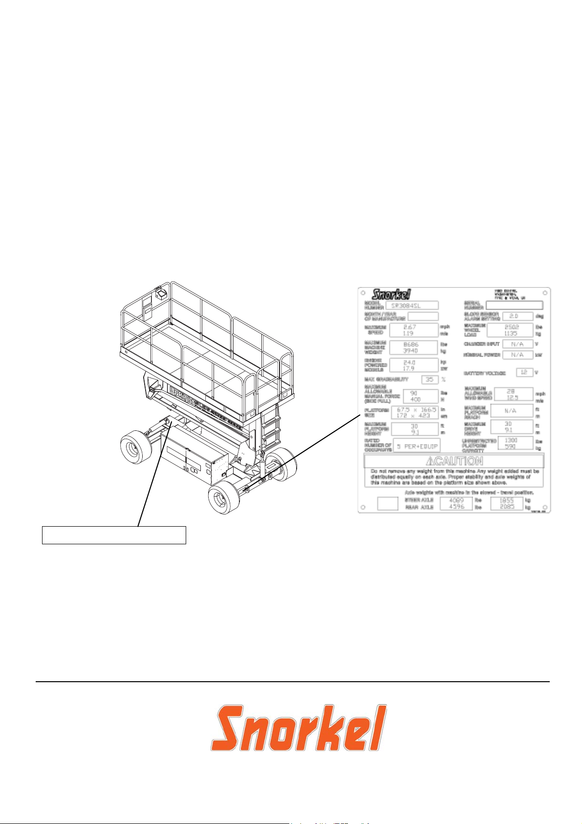
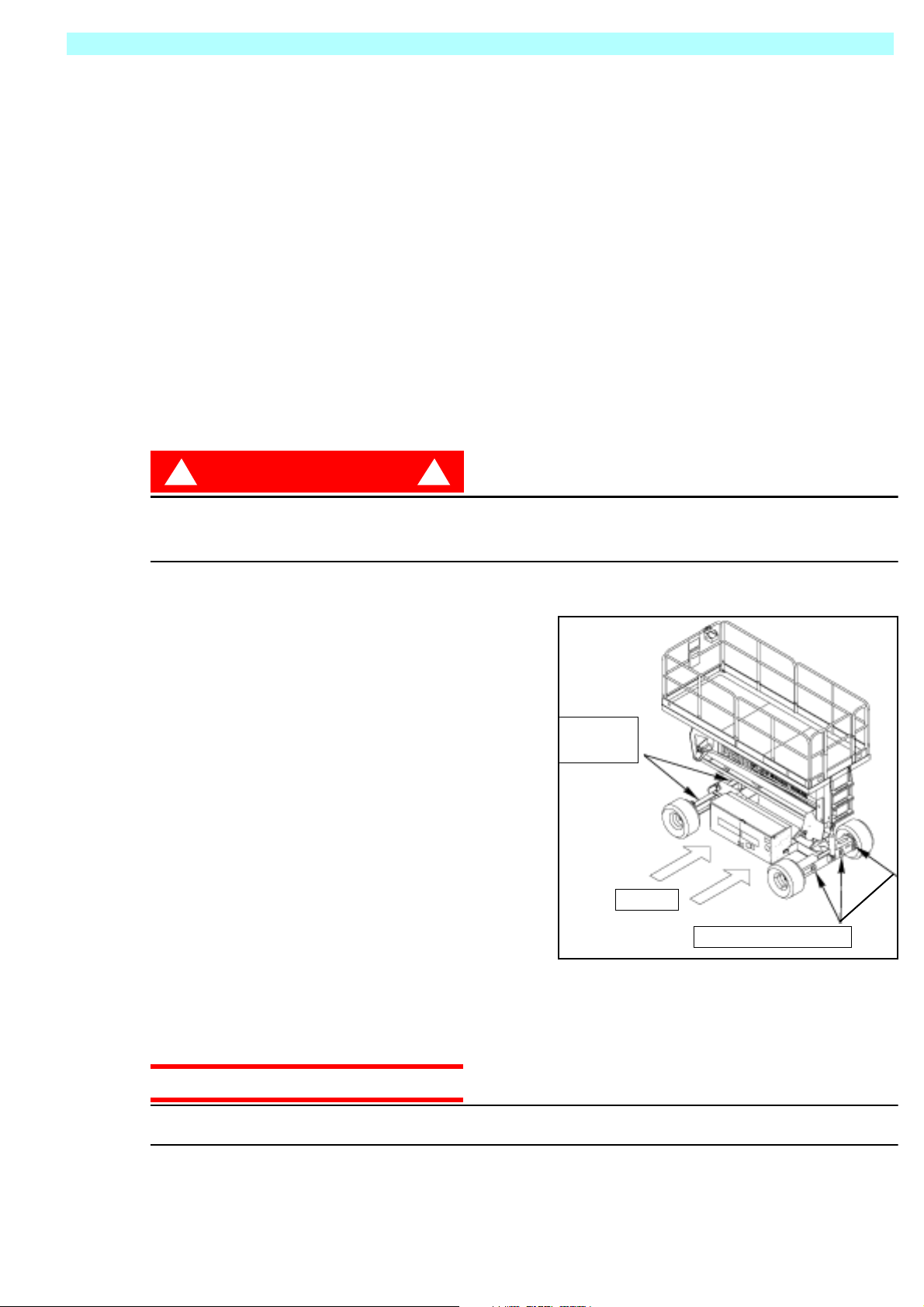
When contacting Snorkel for service or parts information, be sure to include the MODEL and SERIAL NUMBERS from the
equipment nameplate. Should the nameplate be missing, the SERIAL NUMBER is also stamped on top of the chassis
above the front axle pivot.
Stamped Serial Number
TEXT FOR ILLUSTRATION PURPOSE ONLY
www .snorkelusa.com
Page 4

Page 5

OPERATION MANUAL
C
WARNING
All personnel shall carefully read, understand and follow all safety rules and operating
instructions before operating or performing maintenance on any Snorkel work platform.
Safety Rules
Electrocution Hazard Tip Over Hazard
THIS MACHINE IS NOT
INSULATED!
USE OF THE AERIAL WORK PLATFORM: This aerial work platform is intended to lift persons and his tools as well as the material
used for the job. It is designed for repair and assemb ly jobs and assignments at overhead workplaces (ceilings, cranes, roof structures,
buildings etc.). All other uses of the aerial work platform are prohibited!
THIS AERIAL WORK PLATFORM IS NOT INSULATED! For this reason it is imperative to keep a safe distance from live parts of electrical equipment!
Exceeding the specified permissible maximum load is prohibited! See “Special Limitations” on page 4 for details.
The use and operation of the aerial work platform as a lifting tool or a crane (lifting of loads from below upwards or from up high on
down) is prohibited!
NEVER exceed the manual force allowed for this machine. See “Special Limitations” on page 4 for details.
DISTRIBUTE all platform loads evenly on the platform.
NEVER operate the machine without first surveying the work area for surface hazards such as holes, drop-offs, bumps, curbs, or debris;
and avoiding them.
OPERATE machine only on surfaces capable of supporting wheel loads.
NEVER operate the machine when wind speeds exceed this machine’s wind rating. See “Beaufort Scale” on page 4 for details.
IN CASE OF EMERGENCY push EMERGENCY STOP switch to deactivate all powered functions.
IF ALARM SOUNDS while platform is elevated, STOP, carefully lower platform. Move machine to a firm, level surface.
Climbing up the railing of the platform, standing on or stepping from the platform onto buildings, steel or prefab concrete structures, etc.,
is prohibited!
Dismantling the swing gate or other railing components is prohibited! Always make certain that the swing gate is closed and securely
locked!
It is prohibited to keep the swing gate in an open position (held open with tie-straps) when the platform is raised!
To extend the height or the range by placing of ladders, scaffolds or similar devices on the platform is prohibited!
NEVER perform service on machine while platform is elevated without blocking elevating assembly.
INSPECT the machine thoroughly for cracked welds, loose or missing hardware, hydraulic leaks, loose wire connections, and damaged
cables or hoses before using.
VERIFY that all labels are in place and legible before using.
NEVER use a machine that is damaged, not functioning properly, or has damaged or missing labels.
To bypass any safety equipment is prohibited and presents a danger for the persons on the aerial work platform and in its working
range.
NEVER charge batteries near sparks or open flame. Charging batteries emit explosive hydrogen gas.
Modifications to the aerial work platform are prohibited or permissible only at the approval by
AFTER USE, secure the work platform from unauthorized use by turning both keyswitches off and removing key.
NEVER elevate the platform or drive
the machine while elevated unless the
machine is on a firm, level surface.
ollision Hazard Fall Hazard
NEVER position the platform
without first checking for overhead
obstructions or other hazards.
Snorkel.
NEVER climb, stand, or sit on
platform guardrails or midrail.
Page 1
Page 6

505562-100
C
ONTENTS
Introduction. . . . . . . . . . . . . . . . . . . . . . . . . . . . . . . . . . . . . . . . . . . . . . . . . . . . . . . . . . . . . . . . . . . . . . . . . .3
General Description . . . . . . . . . . . . . . . . . . . . . . . . . . . . . . . . . . . . . . . . . . . . . . . . . . . . . . . . . . . . . . . . . . .3
Special Limitations. . . . . . . . . . . . . . . . . . . . . . . . . . . . . . . . . . . . . . . . . . . . . . . . . . . . . . . . . . . . . . . . . . . .4
Platform Capacity . . . . . . . . . . . . . . . . . . . . . . . . . . . . . . . . . . . . . . . . . . . . . . . . . . . . . . . . . . . . . . . . . . . . . . . . . . . 4
Manual Force . . . . . . . . . . . . . . . . . . . . . . . . . . . . . . . . . . . . . . . . . . . . . . . . . . . . . . . . . . . . . . . . . . . . . . . . . . . . . . 4
Beaufort Scale. . . . . . . . . . . . . . . . . . . . . . . . . . . . . . . . . . . . . . . . . . . . . . . . . . . . . . . . . . . . . . . . . . . . . . . . . . . . . . 4
Lift Overload Alarm . . . . . . . . . . . . . . . . . . . . . . . . . . . . . . . . . . . . . . . . . . . . . . . . . . . . . . . . . . . . . . . . . . . . . . . . . . 4
Controls and Indicators . . . . . . . . . . . . . . . . . . . . . . . . . . . . . . . . . . . . . . . . . . . . . . . . . . . . . . . . . . . . . . . .5
Pre-Operation Safety Inspection . . . . . . . . . . . . . . . . . . . . . . . . . . . . . . . . . . . . . . . . . . . . . . . . . . . . . . . . .6
System Function Inspection . . . . . . . . . . . . . . . . . . . . . . . . . . . . . . . . . . . . . . . . . . . . . . . . . . . . . . . . . . . .7
Operation. . . . . . . . . . . . . . . . . . . . . . . . . . . . . . . . . . . . . . . . . . . . . . . . . . . . . . . . . . . . . . . . . . . . . . . . . . . .8
Platform Extension . . . . . . . . . . . . . . . . . . . . . . . . . . . . . . . . . . . . . . . . . . . . . . . . . . . . . . . . . . . . . . . . . . . . . . . . . . 8
Travel With the Platform Lowered. . . . . . . . . . . . . . . . . . . . . . . . . . . . . . . . . . . . . . . . . . . . . . . . . . . . . . . . . . . . . . . 8
Steering. . . . . . . . . . . . . . . . . . . . . . . . . . . . . . . . . . . . . . . . . . . . . . . . . . . . . . . . . . . . . . . . . . . . . . . . . . . . . . . . . . . 8
Elevating the Platform. . . . . . . . . . . . . . . . . . . . . . . . . . . . . . . . . . . . . . . . . . . . . . . . . . . . . . . . . . . . . . . . . . . . . . . . 8
Travel With the Platform Elevated. . . . . . . . . . . . . . . . . . . . . . . . . . . . . . . . . . . . . . . . . . . . . . . . . . . . . . . . . . . . . . . 9
Lowering the Platform . . . . . . . . . . . . . . . . . . . . . . . . . . . . . . . . . . . . . . . . . . . . . . . . . . . . . . . . . . . . . . . . . . . . . . . . 9
Levelling the Platform . . . . . . . . . . . . . . . . . . . . . . . . . . . . . . . . . . . . . . . . . . . . . . . . . . . . . . . . . . . . . . . . . . . . . . . . 9
Emergency Lowering. . . . . . . . . . . . . . . . . . . . . . . . . . . . . . . . . . . . . . . . . . . . . . . . . . . . . . . . . . . . . . . . . . . . . . . . 10
Fold Down guardrails, . . . . . . . . . . . . . . . . . . . . . . . . . . . . . . . . . . . . . . . . . . . . . . . . . . . . . . . . . . . . . . . . . . . . . . . 11
Fold Down Procedure . . . . . . . . . . . . . . . . . . . . . . . . . . . . . . . . . . . . . . . . . . . . . . . . . . . . . . . . . . . . . . . . . . . 11
Erection Procedure . . . . . . . . . . . . . . . . . . . . . . . . . . . . . . . . . . . . . . . . . . . . . . . . . . . . . . . . . . . . . . . . . . . . . 11
Towing or Winching . . . . . . . . . . . . . . . . . . . . . . . . . . . . . . . . . . . . . . . . . . . . . . . . . . . . . . . . . . . . . . . . . .12
Parking Brake Release . . . . . . . . . . . . . . . . . . . . . . . . . . . . . . . . . . . . . . . . . . . . . . . . . . . . . . . . . . . . . . . . . . . . . . 12
After Use Each Day. . . . . . . . . . . . . . . . . . . . . . . . . . . . . . . . . . . . . . . . . . . . . . . . . . . . . . . . . . . . . . . . . . . . . . . . . 12
Hour Meter . . . . . . . . . . . . . . . . . . . . . . . . . . . . . . . . . . . . . . . . . . . . . . . . . . . . . . . . . . . . . . . . . . . . . . . . . . . . . . . 12
Transporting the Work Platform . . . . . . . . . . . . . . . . . . . . . . . . . . . . . . . . . . . . . . . . . . . . . . . . . . . . . . . .13
Preparation for Shipment . . . . . . . . . . . . . . . . . . . . . . . . . . . . . . . . . . . . . . . . . . . . . . . . . . . . . . . . . . . . . . . . . . . . 13
Lifting By Crane. . . . . . . . . . . . . . . . . . . . . . . . . . . . . . . . . . . . . . . . . . . . . . . . . . . . . . . . . . . . . . . . . . . . . . . . . . . . 13
By Forklift . . . . . . . . . . . . . . . . . . . . . . . . . . . . . . . . . . . . . . . . . . . . . . . . . . . . . . . . . . . . . . . . . . . . . . . . . . . . . . . . 13
Driving or Winching onto a Truck or Trailer. . . . . . . . . . . . . . . . . . . . . . . . . . . . . . . . . . . . . . . . . . . . . . . . . . . . . . . 13
Maintenance . . . . . . . . . . . . . . . . . . . . . . . . . . . . . . . . . . . . . . . . . . . . . . . . . . . . . . . . . . . . . . . . . . . . . . . .14
Blocking The Elevating Assembly. . . . . . . . . . . . . . . . . . . . . . . . . . . . . . . . . . . . . . . . . . . . . . . . . . . . . . . . . . . . . . 14
Scissor Brace Installation . . . . . . . . . . . . . . . . . . . . . . . . . . . . . . . . . . . . . . . . . . . . . . . . . . . . . . . . . . . . . . . . . 14
Scissor Brace Stowage . . . . . . . . . . . . . . . . . . . . . . . . . . . . . . . . . . . . . . . . . . . . . . . . . . . . . . . . . . . . . . . . . . 14
Battery Maintenance . . . . . . . . . . . . . . . . . . . . . . . . . . . . . . . . . . . . . . . . . . . . . . . . . . . . . . . . . . . . . . . . . . . . . . . . 15
Battery Charging . . . . . . . . . . . . . . . . . . . . . . . . . . . . . . . . . . . . . . . . . . . . . . . . . . . . . . . . . . . . . . . . . . . . . . . 15
Fault Codes . . . . . . . . . . . . . . . . . . . . . . . . . . . . . . . . . . . . . . . . . . . . . . . . . . . . . . . . . . . . . . . . . . . . . . . . . . . 16
Inspection and Maintenance Schedule . . . . . . . . . . . . . . . . . . . . . . . . . . . . . . . . . . . . . . . . . . . . . . . . . . . . . . .17
Daily Preventative Maintenance Checklist. . . . . . . . . . . . . . . . . . . . . . . . . . . . . . . . . . . . . . . . . . . . . . . .17
Specifications . . . . . . . . . . . . . . . . . . . . . . . . . . . . . . . . . . . . . . . . . . . . . . . . . . . . . . . . . . . . . . . . . . . . . . .18
Page 2 SR2684SL & SR3084SL
Page 7
Introduction 505562-100
I
NTRODUCTION
This manual covers operation of the SR2684SL & SR3084SL Series Self-Propelled Work Platforms.
This manual must be stored o n the machine at all times.
G
ENERAL
D
ESCRIPTION
!
WARNING
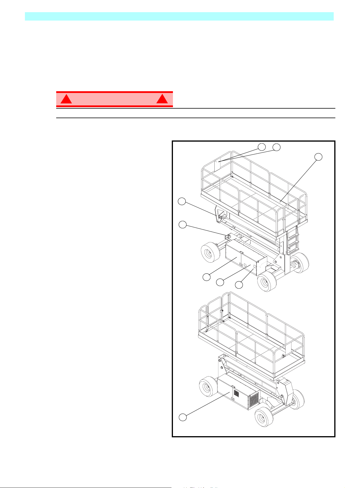
DO NOT use the maintenance platform without guardrails properly assembled and in place
1. Platform
2. Elevating Assembly
3. Chassis
4. Power Module
5. Control Module
6. Platform Controls
7. Manual Case
8. Chassis Controls
9. Hydraulic Fluid Reservoir
!
Figure 1: SR2684SL & SR3084SL
7
6
2
3
1
5
8
4
9
SR2684SL & SR3084SL Page 3
Page 8
505562-100 Special Limitations
S
PECIAL
P
M
L
IMITATIONS
Travel with the platform raised is limited to creep speed range.
Elevating the Work Platform is limited to firm, level surfaces only.
DANGER
! !
The elevating function shall ONLY be used when the work platform is leveled and on a firm surface.
The work platform is NOT intended to be driven over uneven, rough, or soft terrain.
LATFORM
The maximum capacity for the MACHINE, including occupants is determined by model and options, and
is listed in “Specifications” on page 18.
DANGER
! !
DO NOT exceed the maximum platform capacity or the platform occupancy limits for this machine.
ANUAL
Manual force is t he force applied by the o ccupant s to object s such as w alls or oth er structures outside the
work platform .
F
C
APACITY
ORCE
The maximum allowable manual for ce is limited to 200 N ( 45 lb s.) of force per occupant , with a ma ximum
of 400 N (90 lbs.) for two or more occupants.
DANGER
! !
DO NOT exceed the maximum amount of manual force for this machine.
B
EAUFORT
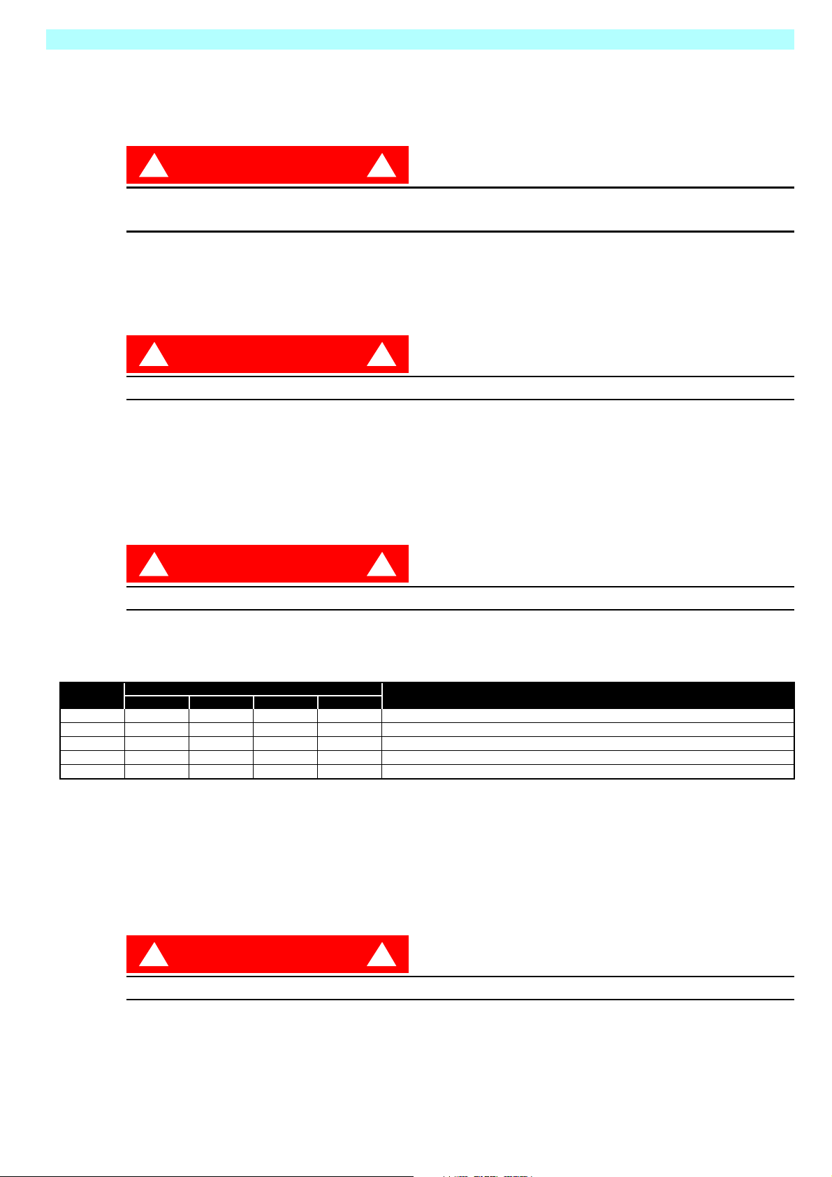
Never operate the machine when wind speeds exceed 12.5m/s (28 mph) [Beaufort scale 6].
BEAUFORT
RATING
3 3,4~5,4 12,25~19,4 11.5~17.75 7.5~12.0 Papers and thin branches move, flags wave.
4 5,4~8,0 19,4~28,8 17.75~26.25 12.0~18 Dust is raised, paper whirls up, and small branches sway.
5 8,0~10,8 28,8~38,9 26.25~35.5 18~24.25 Shrubs with leaves start swaying. Wave crests are apparent in ponds or swamps.
6 10,8~13,9 38,9~50,0 35.5~45.5 24.5~31 Tree branches move. Power lines whistle. It is difficult to open an umbrella.
7 13,9~17,2 50,0~61,9 45.5~56.5 31.~38.5 Whole trees sway. It is difficult to walk against the wind.
m/s km/h ft/s mph
L
IFT
O
If a load equivelent to 90% of safe working load is lifted a fault code “03” will be displayed on the digital
display on the platform control box. If a load which is greater than the safe working load is present in the
basket all machine functions will cease to operate and an acoustic warning will sound. In order to return to
normal operation a load equal to or less than the saf e w orking load must be present in the bask e t and the
power must be re-cycled, power can be re-cycled by pushing the emergency stop button and releasing it
again.
WIND SPEED
VER L OA D
S
CALE
A
LARM
GROUND CONDITIONS
DANGER
! !
Never operate the machine with a platfo rm load greater than the rated capacity.
Page 4 SR2684SL & SR3084SL
Page 9
Controls and Indicators 505562-100
C
ONTROLS
AND
I
NDICATORS
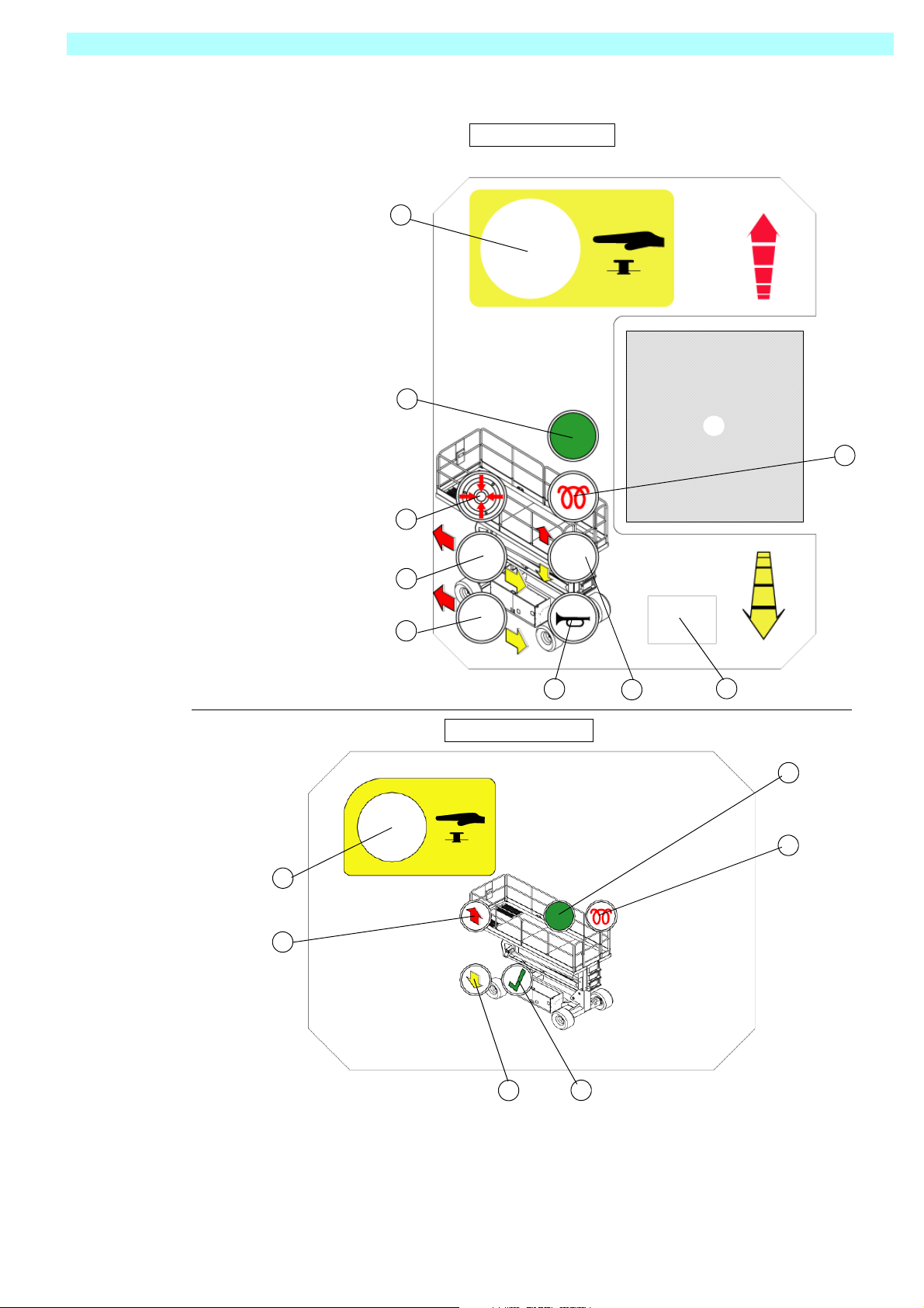
Figure 2: Controls and Indicators
Platform Controls
8
7
10
6
1 Drive (Hi Speed)
2. Drive (Low Speed)
3. Level
4. Horn Button
5. Lift/Lower Button
6. Glow Plug
7. Engine Start
8. Emergency Stop Button
9. Display
10. Joystick
1
2
3
2
1
4
Chassis Controls
5
9
6
5
1. Emergency Stop
2. Elevate
3. Descend
4. Enable
5. Glow Plug
6. Start
3
4
SR2684SL & SR3084SL Page 5
Page 10

505562-100 Pre-Operation Safety Inspection
P
RE
-O
PERATION
NOTE: Carefully read, understand and follow all safety rules, operating instructions, labels and
National Safety Instructions/Requirements. Perform the following steps each day before use.
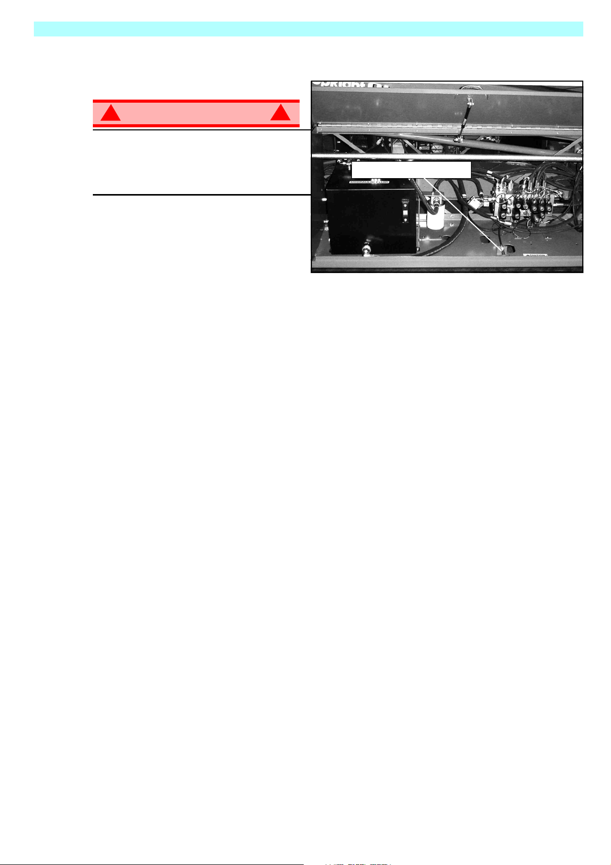
1. Open modules and inspect for damage, fluid leaks or missing parts.
2. Check the leve l of the h ydraulic fluid with
the platform fully lowered. The hydraulic
reservoir is located in the Control Module Door. The fluid level must be
between the MIN and MAX lines. Add
hydraulic fluid if necessary.
3. Check that fluid level in the starter battery is correct.
4. Check the level of the Diesel fuel with
the engine switched off. The fuel tank is
located in the Power Module. Add fuel
as required.
5. Check that all guardrails are in place
and all fasteners are properly tightened.
6. Inspect the machine thoroughly for
cracked welds and structural damage,
loose or missing hardware, hydraulic
leaks, damaged control cable, loose
wire connections and wheel bolts.
S
AFETY
I
NSPECTION
Figure 3: Hydraulic Tank
Page 6 SR2684SL & SR3084SL
Page 11

System Function Inspection 505562-100
S
YSTEM
F
UNCTION
Refer to Figure 2 (Page 5) for the locations of various controls and indicators.
I
NSPECTION
!
WARNING
STAND CLEAR of the work platform while performing the following checks.
Before operat ing the work platform, survey the work area for surface hazards such as holes, drop-offs,
bumps and debris.
Check in ALL directions, including above the work platform, for obstructions and electrical cond u cto rs.
Protect the control console cable from possible damage while performing checks.
1. Move the machine, if necessary, to an unobstructed area to allow for full elevation.
2. Twist Chassis Emergency Stop Switch to the ON position.
3. Twist Platform Emergency Stop Switch to the ON position.
4. Turn the Key Switch to the ON position.
5. Visually inspect the elevating assembly, lift cylinder, cables, and hoses for cracked welds and structural
damage, loose hardware, hydraulic leaks, loose wire connections, and erratic operation. Check for missing or loose parts.
6. Push the Chassis ELEVATE and ENABLE buttons and fully elevate the platform.
7. Partially lower the platform by pushing Chassis DESCEND and ENABLE buttons, and check for proper
operation of the audible lowering alarm.
8. Open the Emergency Lowering Valve (see Figure 4) by pulling the knob out to check for proper operation. When the platform is low ered, release the knob.
9. Push the Chassis Emergency Stop Switch to check for proper operation. All machine functions should
be disabled. Twist the Chassis Emergency Stop Switch to resume.
10. Check that the route is clear of obstacles (persons, obstructions, holes, and drop-offs, bumps and
debris), is level, and is capable of supporting the wheel loads.
11. Mount the platform and properly close the entrance.
12. Select DRIVE mode.
!
NOTE: Use both HI and LOW drive (if applicable) when performing the following step.
13. While engaging the Safety Interlock Trigger , mo ve the Joystick to FORWARD, then REVERSE, to check
for speed control.
14. Push the Steering Switch RIGHT, then LEFT, to check for steering control.
15. Select LIFT mode. Grasp the Joystick, engaging the Safety Interlock Trigger, and push it forward to
check platform lift controls. Raise the platform to full elevation.
16. Pull back on the Joystic k. The platform should descend and the audible lowering alarm should sound.
17. Push the Platform Emergency Stop Switch to check for proper operation. All machine functions should
be disabled. Pull out the Platform Emergency Stop Switch to resume.
SR2684SL & SR3084SL Page 7
Page 12

505562-100 Operation
O
PERATION
Before operating t he wo rk platform, ensure that the Pre-Operation Saf ety Inspe ction has bee n comple ted
and that any deficiencies ha v e been cor rected. Ne ver opera te a dama ged or malfunctioning mac hine.
The operator must be thoroughly tr ained on this machine.
S
TARTING THE
1. Mount the platform and properly close the entrance.
2. Depress and hold the GLOW PLUG button for approximately 5 seconds.
3. Press green START button.
T
RAVEL
1. Check that the route is clear of obstacles (persons, obstructions, holes, drop-offs, bumps, and debris),
is level, and is capable of supporting the wheel loads.
2. Verify that the Engine is started and the Chassis Emergency Stop Switch is ON (pulled out).
3. Mount the platform and properly close the entrance.
4. Check clearances above, below, and to the sides of platform.
5. Twist the Platform Emergency Stop Switch out to the ON position.
6. Select DRIVE mode.
W
ITH THE
E
NGINE
P
LATFORM
L
OWERED
NOTE: Choose between standard drive and extra torque depending on the gradient.
7. Engage the Safety Interlock Trigger and move the Joystick to FORWARD or REVERSE to travel in the
desired direction. The speed of the machine will vary depending on how far from center the Joystick is
moved.
S
TEERING
1. Turn the Drive/Lift Switch to DRIVE.
2. While engaging the Safety Interlock Trigger, push the Steering Switch to RIGHT or LEFT to turn the
wheels in the desired direction. Observe the tires while maneuvering the work platform to ensure proper
direction.
NOTE: Steering is not self-centering. Wheels must be returned to the straight ahead positi on by
operating the Steering Switch.
E
LEVATING
1. Select a firm, level surface.
2. Select LIFT mode.
3. While engaging the Safety Interlock Trigger, push the Joystick forward.
4. If the machine is not level the tilt alarm will sound and the machine will not lift or drive.
5. If the tilt alarm sounds the platform must first be fully lowered, then elevate the platform approximately
600mm (2ft), stop, press and hold the LEVEL button until the tilt alarm is silenc ed . On ly the n can you
elevate fully. If the platform is not levelled correctly the tilt alarm will continue to sound and lift functions
will be cut at a height of approximately 2m (6ft).
THE
P
LATFORM
Page 8 SR2684SL & SR3084SL
Page 13

Operation 505562-100
T
RAVEL
NOTE: The machine will travel at reduced speed when the platform is elevated.
1. Check that the route is clear of obstacles (persons , obstructions , holes, drop-offs , bump s, and debris), is
level, and is capable of supporting the wheel loads.
2. Check clearances above, below, and to the sides of platf orm.
3. Select DRIVE mode.
4. Engage the Safety Interlock Trigger on the Joystick and move to FORWARD or REVERSE to travel in
the desired direction. The speed of the machine will vary depending on how far from center the Joystick
is moved.
5. If the machine is not level the tilt alarm will sound and the machine will not lift or drive. If the tilt alarm
sounds the platform must be lowered and the machine moved to a firm, level surface before attempting
to re-elevate the platform.
L
OWER ING THE
1. Select LIFT mode.
2. Check around the base of the platf orm to ensure that no one is in cont act with the mach ine . Engag e the
Safety Interlock Trigger and pull back on the Joystick to lower the platform.
3. The platform will stop when it reaches the PPE cutout height. Inspect around the machine to ensure no
one is in contact with the machine. After a four-second time delay, lower the platform as in step 2.
W
ITH THE
P
P
LATFORM
LATFORM
E
LEVATED
L
EVELLING
The AUTO LEVEL feature is designed to level the platform in a situation where the ground has no more
than a 13 degree slope side to side and 9 degr ees fore and aft, if the slope is gr eater tha n 13 deg rees side
to side and 9 degrees fore and aft the AUTO LEVEL feature will not function.
The tilt alarm will continue to sound until the platform is level
1. Check that the route is clear of obstacles (persons , obstructions , holes, drop-offs , bump s, and debris), is
level, and is capable of supporting the wheel loads.
2. Check clearances above, below, and to the sides of platf orm.
3. Elevate the platform approximately 600mm (2ft).
4. Press and hold the AUTO LEVEL and Engage the Safety Interlock Trigger until the platform is level and
the tilt alarm is silenced.
5. In this condition only the ELEVATE and DESCEND functions will work.
6. If you need to drive you must descend and return the platform to it’s normal inclanation.
THE
P
LATFORM
SR2684SL & SR3084SL Page 9
Page 14
505562-100 Operation
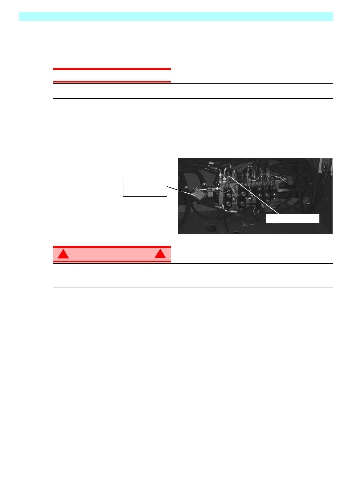
E
MERGENCY
L
OWER ING
Figure 4: Emergency Lowering Valve
!
WARNING
If the platform should fail to lower, NEVER
climb down the elevating assembly.
Stand clear of the elevating assembly while
operating the Emergency Lowering Valve
Knob.
!
Emergency Lowering Knob
SR2684SL & SR3084SL
The Emergency Lowering Valve for the
SR2684SL & SR3084SL is located in the
control module of the machine and is
accessable through an opening in the control module door.
1. Open the Emergency Lowering Valve by pulling and holding the handle.
2. To close, release the knob. The platform will not elevate if the Emergency Lowering Valve is open.
Page 10 SR2684SL & SR3084SL
Page 15
Operation 505562-100
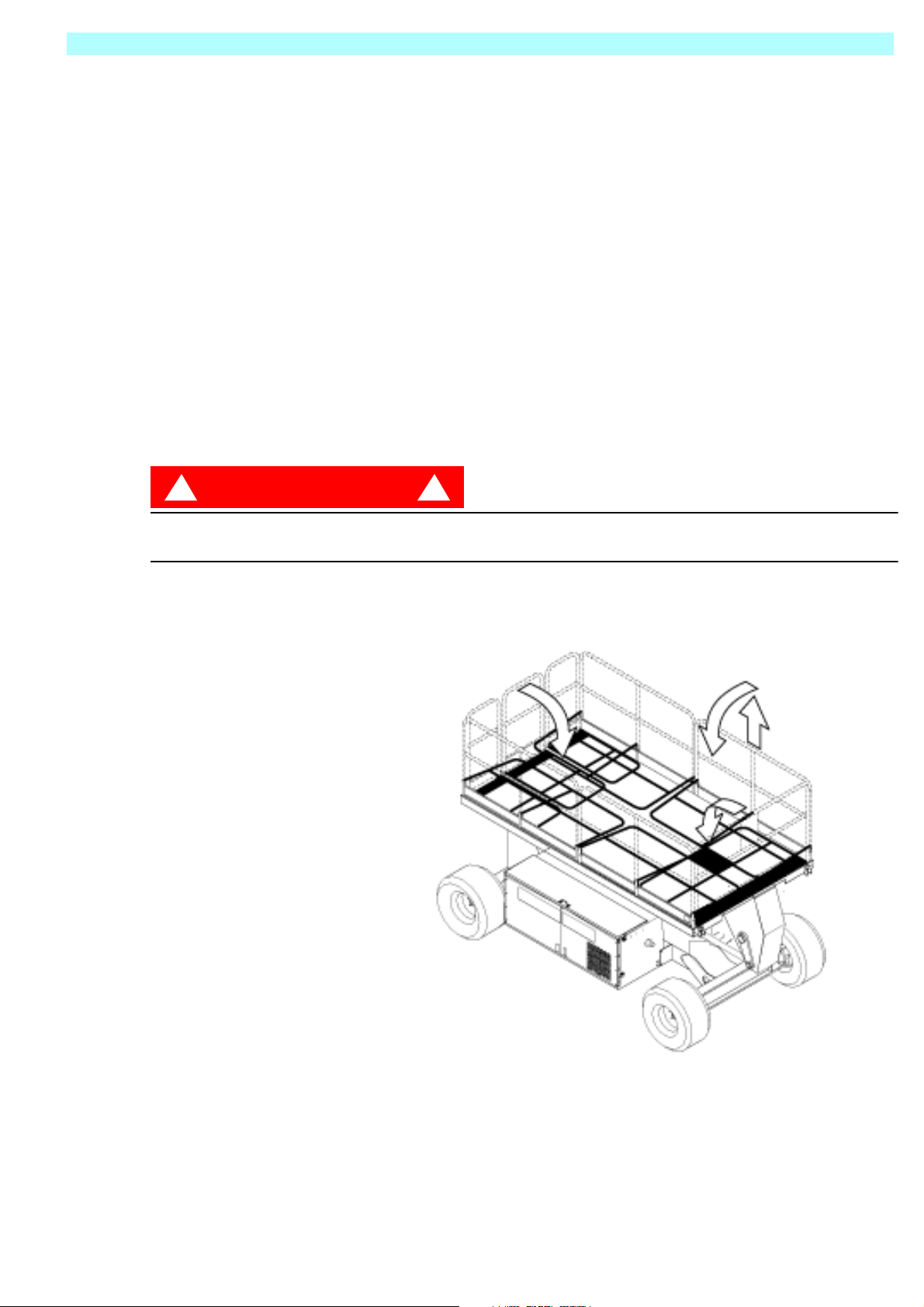
F
OLD
This procedure applies only to the SR2684SL & SR3084SL models for the purpose of passing through a
standard double doorway. Guardrails must be returned to proper position before using the
F
OLD
1. Unhook the controller from the side guardrail and place it on the floor of the platform.
2. Starting at the front of the platform, remove nuts, bolts and washers from the top of the front guardrail.
Fold the front guardrail down onto the platf orm.
3. Close and latch gate.
4. Remove nuts, bolts and washers from the top of the rear guardrail. Fold the rear guardrail down onto the
platform being careful to keep latched at all times.
5. Remove nuts, bolts and washers from the top of the side guardrails. Lift up and fold one side guardrail in
so it rests on the deck. Repeat with other side guardrails.
E
RECTION PROCEDURE
D
OWN GUARDRAILS
D
OWN PROCEDURE
1. Raise side guardrails, making sure each is pushed down to secure the guardrail in the vertical
position.
2. Install bo lts, washers and nuts between the side guardrails, tighten securely.
3. Raise rear guardrail assembly, aligning holes and install bolts, washers and nuts. Tighten securely.
DANGER
! !
Before entering platform, guardrails must be securely fastened in their proper position.
SR2684SL & SR3084SL Page 11
Page 16
505562-100 Towing or Winching
T
OWIN G OR
Perform the following only when the machine will not operate under its own power and it is necessary to
move the machine or when winching onto a transport vehicle (see “Transporting the Work Platform” on
page 13).
W
INCHING
CAUTION
DO NOT tow or winch the machine faster than 0,3 m/s (1 ft./s). Faster speeds will damage drive
components and void the w arranty.
B
RAKE
Perform the following only when the machine will not operate under it’s own power and it is necessary to
move the machine or when towing the machine up a grade or onto a trailer to transport.
1. Close the needle valve by turning the allen screw clockwise.
2. Pump the Brake Release Pump until the Parking Brake Cylinder Rod clears the wheel rotor.
3. The machine will now roll when pushed or pulled.
4. Open needle valve and verify that the
cylinder rod has extended before the
machine is operated.
R
ELEASE
P
UMP
Hand Pump
Needle Valve
!
WARNING
Never tow faster than 0,3 m/sec. (1 ft./sec.).
Never op erate the work platform with the parking brakes released. Serious injury or damage could
result.
A
FTER
1. Ensure that the platform is fully lowered.
2. Park the machine on a firm level surface, pre ferably under cover, secure against vandals, children and
unauthorized operation.
3. Turn the Chassis Key Switch to OFF and remove the key to prevent unauthorized operation.
H
OUR
To access the hour meter function perform the following steps.
U
M
SE
ETER
E
ACH
!
D
AY
1. Climb into the basket (with the machine powered up)
2. Push the platform emergency stop button.
3. Hold down the following buttons, Horn & Lift.
4. While holding the buttons twist the emergency stop button to return power to the machine.
5. “hr” will now be displayed on the readout, Pressing the right turn button will scroll through the accumulated
hours two digits at a time. For example, if pressing the right turn button once displays “20”, pressing it a
2nd time displays “58”, and pressing it a 3rd time displays “hr”, the elapsed time of operation is 2058
hours.
Page 12 SR2684SL & SR3084SL
Page 17
Transporting the Work Platform 505562-100
T
RANSPORTING
P
REPARATION FOR
1. Fully lower the platform.
2. Disconnect the battery negative (-) lead from the battery terminal.
3. Band the controller to the front guardrail.
4. Band the elevating linkage t o the frame.
L
IFTING
1. Secure straps to chassis tie down/lifting lugs only.
2. Place the platform onto the transport vehicle in transport position.
3. Chock the wheels.
4. Secure the work platform to the transport vehicle with chains or straps of adequate loa d capacity
attached to the chassis tie down/lifting lugs.
B
Y
THE
C
W
RANE
ORK
S
HIPMENT
P
LATFORM
BY F
! !
Forklifting is for transport only.
See specifications for weight of work platform and be certain that forklift is of adequate capacit y to lift
the work platform.
Forklift from the side by lifting under the Chassis Modules.
D
RIVING OR
ONTO
RAILER
T
NOTE: Do not winch faster than 0,3 m/s (1 ft/s).
1. Move the machine onto the truck or trailer;
A. To Drive the machine onto the transport vehicle:
B. To Winch the machine onto the transport vehicle:
2. Secure the work platform to the transport vehicle with chains or straps of adequate loa d capacity
ORKLIFT
DANGER
W
INCHING
A T
a. Move the work platform up the ramp and into
transport position.
b. Set the wheels straight and turn off the machine.
c. Chock the wheels.
a. Move the work platform up to the ramp.
b. Attach the winch cable to the tie down/lifting lugs.
c. Release the parking brakes (refer to “Towing or
Winching” on page 12).
d. Winch the platform into transport position
e. Chock the wheels.
attached to the chassis tie down/lifting lugs.
RUCK OR
Front Tie
Down and
Lifting Lugs
Figure 5: Transporting the Work Platform
Forklift
Rear Tie Down/Lift
CAUTION
Overtightening of the chains or straps attached to the Tie Down/Lifting Lugs may result in damage to
work platform .
SR2684SL & SR3084SL Page 13
Page 18
505562-100 Maintenance
M
AINTENANCE
!
WARNING
Never pe rform service while the platform is elevated without first blockin g the elevating assembly.
DO NOT stand in the elevating assembly area while deploying or storing the brace.
B
LOCKING
LEVATING
E
T
HE
A
SSEMBLY
!
Figure 6: Scissor Brace
INSTALLATION
1. P ark the work platform on firm, level ground and
leave the engine running.
2. Ensure the Chassis Emergency Stop Button is
twisted to the ON position.
3. Press and hold the Chassis LIFT and ENABLE
buttons to elevate the platform approximately
305 mm (12 inches).
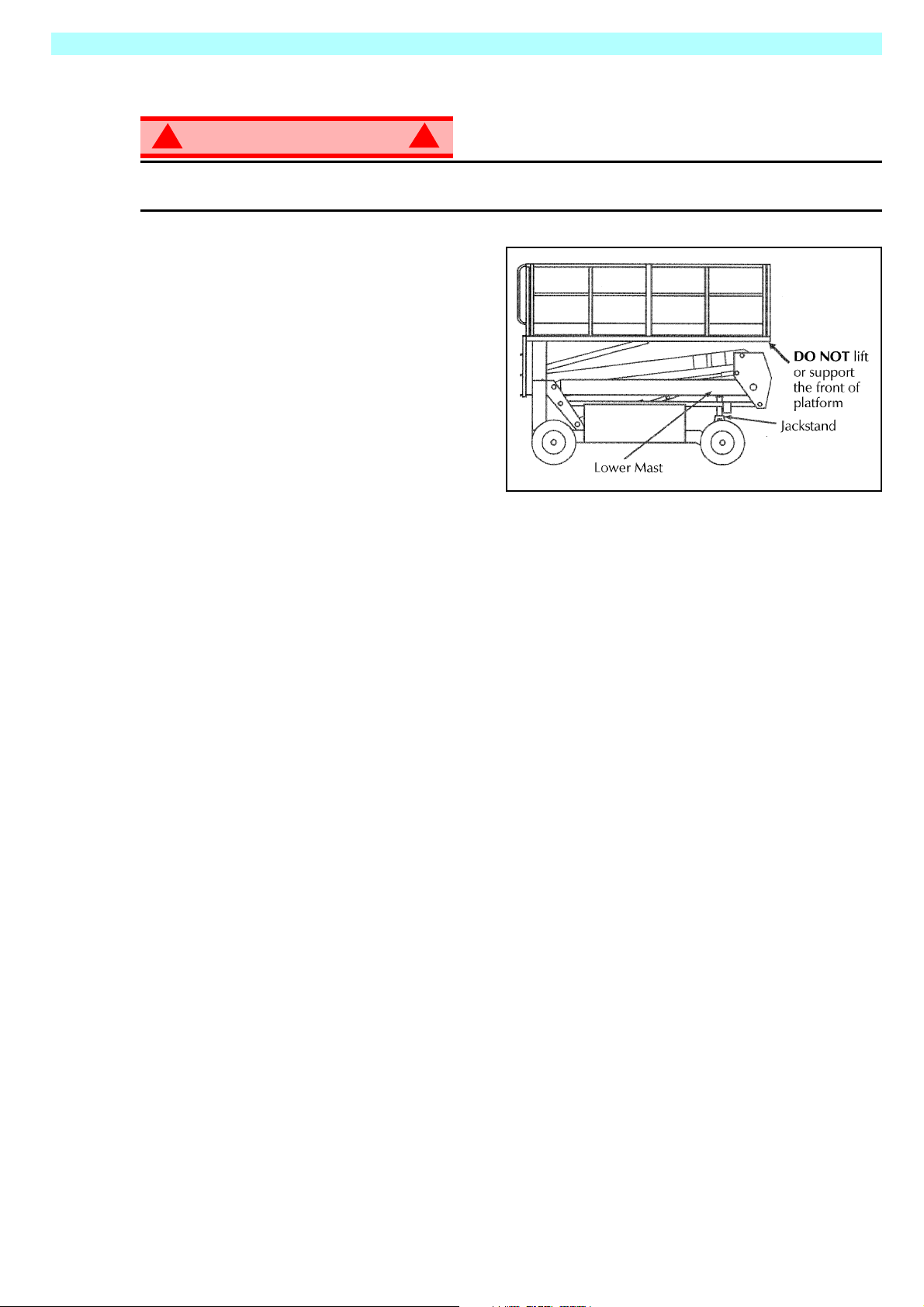
4. Place a jackstand with a minimum rating of
1814 kg (4000 lbs.) between the lower mast and chassis, just behind the front axle.
5. Press and hold the Chassis DESCEND and ENABLE buttons to lower the platform until jackstand is
secured tightly between lower mast and Chassis.
REMOVAL
1. Press and hold the Chassis LIFT and ENABLE buttons to elevate the platform until the jackstand can
be removed.
2. Remove jackstand.
3. Press and hold the Chassis DESCEND and ENABLE buttons to completely lower the platform.
Page 14 SR2684SL & SR3084SL
Page 19

Maintenance 505562-100
B
ATTERY
M
AINTENANCE
!
WARNING
Hazard of explosive gas mixture. Keep sparks, flame, and smoking material away from batteries.
Always wear safety glasses when working near batteries.
Battery fluid is highly corrosive. Thoroughly rinse away any spilled fluid with clean water.
Always replace batteries with Snorkel batteries or manufacturer approved replacements.
• Check the battery fluid level daily, especially if the work platform is being used in a warm, dry climate.
• If electrolyte level is lower than 10 mm
tap water with high mineral content, as it will shorten battery life.
• Keep the terminals and tops of the batteries clean.
• Refer to the Service Manual to extend battery life and for complete service instructions.
B
ATTERY CHARGING
The battery is charged while the engine is running.
!
3
(
/
in.) above the plates add distilled water only. DO NOT use
8
SR2684SL & SR3084SL Page 15
Page 20

505562-100 Maintenance
F
AULT
01 - SYSTEM INIT ERROR
02 - SYSTEM PLATFORM COM ERROR
03 - PLATFORM OVERLOAD
04 - SYSTEM LOWER PANEL COM ERROR
05 - OIL PRESSURE LOW
06 - COOLANT TEMP HOT
21 - PLATFORM START ON
22 - PLATFORM LEFT TURN SW ON
23 - PLATFORM RIGHT TURN SW ON
24 - PLATFORM LIFT SW ON
25 - PLATFORM HISPEEDDRIVE SW ON
26 - PLATFORM GLOWLP SW ON
27 - PLATFORM LOSPEEDDRIVE SW ON
28 - PLATFORM AUTOLEVEL SW ON
29 - PLATFORM JOYSTICK ENABLE SW ON
C
ODES
31 - PLATFORM JOYSTICK NOT NEUTRAL
34 - GROUND PANEL ENABLE SW ON
37 - GROUND PANEL DOWN SW ON
38 - GROUND PANEL UP SW ON
43 - GROUND PANEL START SW ON
45 - GROUND PANEL GLOWLP SW ON
51 - Coil Fault HiSpeed1
52 - Coil Fault HiSpeed2
55 - Coil Fault LiftUp
56 - Coil Fault LiftDown
57 - Coil Fault TiltLeft
58 - Coil Fault TiltRight
59 - Coil Fault SteerRight
61 - Coil Fault SteerLeft
62 - Coil Fault TiltRear
63 - Coil Fault TiltForward
66 - Coil Fault Forward
67 - Coil Fault Reverse
71 - Coil Fault CushionValve
72 - Coil Fault AxleFloat
73 - Coil Fault SteerDump
68 – LOW BATTERY FAULT
Page 16 SR2684SL & SR3084SL
Page 21
Inspection and Maintenance Schedule 505562-100
I
NSPECTION
The Complete Inspection consists of periodic visual and operational checks, along with periodic minor
adjustments that assure proper performance. Daily inspection will prevent abnormal wear and prolong the
life of all systems. The inspection and maintenance schedule should be performed at the specified intervals. Inspection and maintenance shall be performed by personnel who are trained and familiar with
mechanical and electrical proced u re s.
AND
M
AINTENANCE
S
CHEDULE
D
AILY
M
AINTENANCE
Y = Yes/Acceptable
N = No/Not Acceptable
R = Repaired/Acceptable
!
WARNING
Before performing preventative maintenance, familiarize yourself with the operation of the machine.
Always block the elevating assembly whenever it is necessary to perform maintenance while the
platform is elevated.
The daily preventative maintenance checklist has been designed for machine service and maintenance.
Please photocopy this page and use the checklist when inspecting the machine.
P
REVENTATIVE
T
ABLE KEY
!
M
AINTENANCE
P
Date:_______________________________________
Owner: _____________________________________
Model No:___________________________________
Serial No: ___________________________________
REVENTATIVE
C
M
AINTENANCE
HECKLIST
R
EPORT
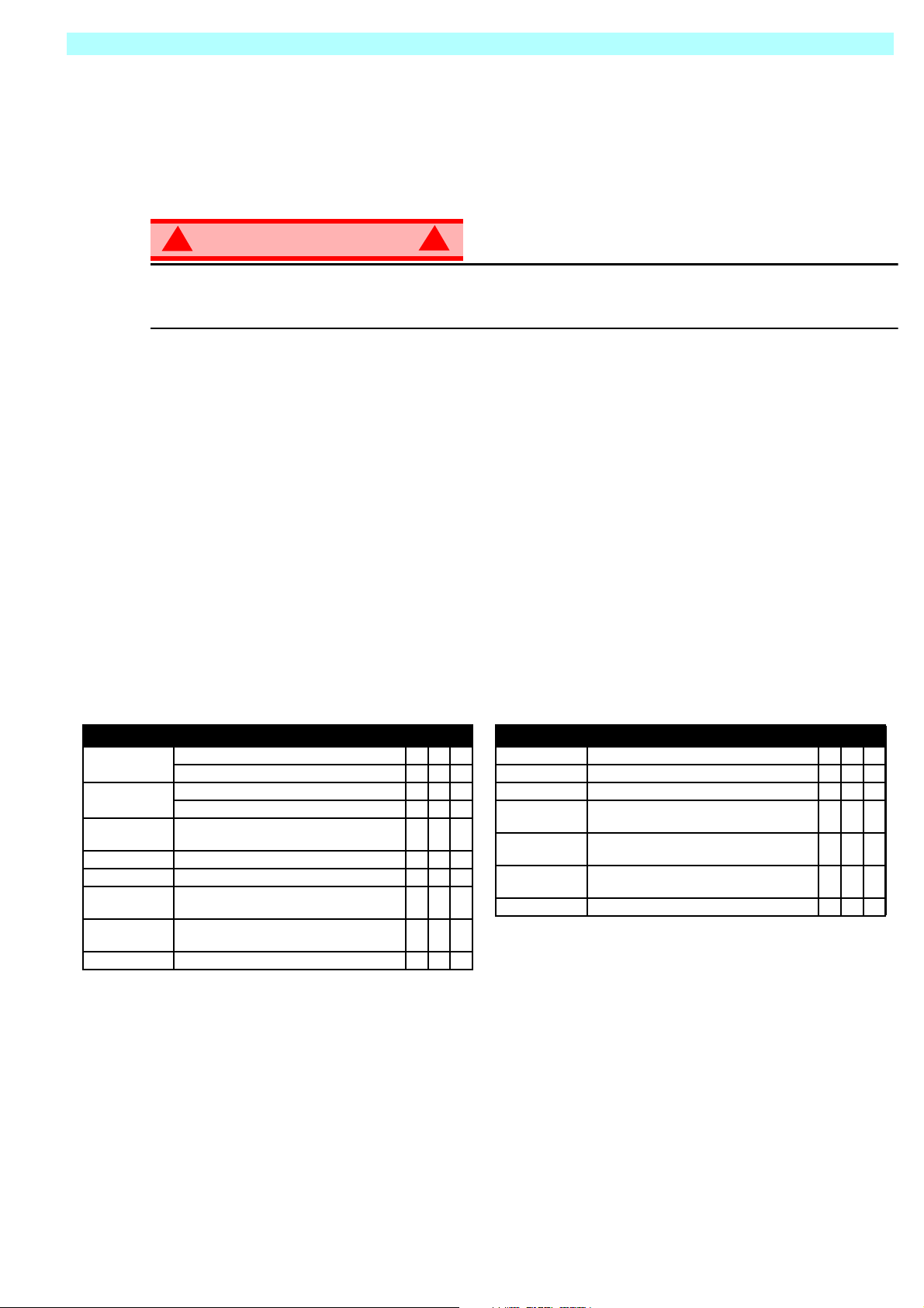
COMPONENT INSPECTION OR SERVICES Y N R
Battery
Chassis
Control Cable
Controller Check switch operation.
Drive Motors Check for operation and leaks.
Elevating
Assembly
Emergency
Lowering System
Entire Unit Check for and repair collision damage.
Check electrolyte level.
Check battery cable condition.
Check hoses for pinch or rubbing points.
Check welds for cracks.
Check the exterior of the cable for pinching,
binding or wear.
Inspect for structural cracks.
Operate the emergency lowering valve and check
for serviceability.
Serviced By:_________________________ ________
COMPONENT INSPECTION OR SERVICES Y N R
Hydraulic Fluid Check fluid level.
Hydraulic Pump Check for hose fitting leaks.
Hydraulic System Check for leaks.
Labels
Platform Deck
and Rails
Platform Deck
and Rails
Tires and Wheels Check for damage.
Check for peeling, missing, or unreadable labels
& replace.
Check welds for cracks.
Check condition of deck.
SR2684SL & SR3084SL Page 17
Page 22

505562-100 Specifications
S
PECIFICATIONS
ITEM
Platform Size (Inside Toeboards)
Standard 1,71 m x 4,22 m [67.5 in. x 166.5 in.] 1,71 m x 4,22 m [67.5 in. x 166.5 in.]
Slide Out Deck Extended 1,71 m x 4,61 m [67.5 in. x 181.5 in.] N/A
Max. Platform Capacity
Standard 680kg [1,500 lbs.] 590 kg [1,300 lbs.]
w/ Extension 680kg [1,500 lbs.] N/A
On Extension 227g [500 lbs.] N/A
Max. No. of occupants
Standard 5 people 5 people
on Extension 2 people N/A
Height
Working Height 9.75 m [32 ft.] 10.97 m [36 ft.]
Max. Platform Height 7.93m [26 ft.] 9,14 m [30 ft.]
Min. Platform Height 1.5 m [59 in.] 1.5 m [59 in.]
Max. Drive Height 7.93 m [26 ft.] 9.14 m [30 ft.]
Dimensions
Weight Diesel: 3,216 kg [7,090 lbs.] Diesel: 3.216 kg [7,090 lbs.]
Overall Width, Standard 2,13 m [84 in.] 2,13 m [84 in.]
Overall Height 2,6 m [102.5 in.] 2,6 m [102.5 in.]
Overall Length, Standard 3.79 m [149 in.] 4,39 m [173 in.]
Surface Speed
Platform Lowered 0 to 5.0 km/h [0 to 3.1 m.p.h.] 0 to 5.0 km/h [0 to 3.1 m.p.h.]
Platform Raised 0 to 0.8 km/h [0 to 0.5 m.p.h.] 0 to 0.8 km/h [0 to 0.5 m.p.h.]
System Voltage 12 Volt DC 12 Volt DC
Hydraulic Tank Capacity 74 l [19.5 US Gallons] 74 l [19.5 US Gallons]
Maximum Hydraulic System Pressure 210 bar [3000 psi] 210 bar [3000 psi]
Hydraulic Fluid
Above 32° f [0° c]) ISO #46 ISO #46
Normal use, below 32° f [0° c]) ISO #32 ISO #32
Below 0° f [-17° c] ISO #15 ISO #15
Lift System One Single Stage Lift Cylinders One Single Stage Lift Cylinders
Lift Speed Raise, 48 sec./Lower, 40 sec. Raise, 48 sec./Lower, 40 sec.
Platform Leveling 13° side to side, 9° Fore and Aft 13° side to side, 9° Fore and Aft
Power Source 20 HP (Diesel) 20 HP (Diesel)
Drive Control Proportional Proportional
Control System Joystick Controller with Safety
Interlock Trigger and Thumb Rocker
Horizontal Drive Four Wheel, Hydraulic Motors Four Wheel, Hydraulic Motors
Tyres (Standard) 26 x 12.00 - 12 NHs Super Terra-grip
ANSI Spec. Pneumatic Tire Pressure Do Not Exceed 57 PSI Do Not Exceed 57 PSI
Parking Brakes Dual Spring Applied, Hydraulic
Turning Radius (inside) 3,96 m [13 ft.] 3,96 m [13 ft.]
Maximum Gradeability 35% [19°] 35% [19°]
Wheel Base 2,54 m [100 in.] 2,54 m [100 in.]
Guardrails 1,11 m [43.5 in.] high, Fold Down with
Toe board 152 mm [6 in.] High 152 mm [6 in.] High
Fuel Tank Capacity 45.5 l [12 US Gallons] 45.5 l [12 US Gallons]
SR2684SL SR3084SL
Joystick Controller with Safety
Interlock Trigger and Thumb Rocker
Steering, Toggle Selector and
Emergency Stop Switches
with Trac Seal
Release, multi-disc
gate.
Steering, Toggle Selector and
Emergency Stop Switches
26 x 12.00 - 12 NHs Super Terra-grip
Dual Spring Applied, Hydraulic
1,11 m [43.5 in.] high, Fold Down with
with Trac Seal
Release, multi-disc
gate.
*Specifications are subject to change without notice. Hot weather or he avy use may affect performance.
Refer to the Service Manual for complete parts and service information.
This machine meets or exceeds all applicable requirements of OSHA and ANSI A92.6-1999.
Page 18 SR2684SL & SR3084SL
Page 23

Specifications 505562-100
SR2684SL & SR3084SL Page 19
Page 24

Page 25

Série SR-2684/3084-SL
Numéros de série 50001 – actuel
FRANÇAIS
Lorsque vous contactez Snorkel pour des informations sur l'entretien ou les pièces, indiquez le MODÈLE ou le NUMÉRO
DE SÉRIE donné sur la plaque signalétique. En cas d'absence de plaque signalétique, le NUMÉRO DE SÉRIE est
également estampé sur le dessus du châssis, au-dessus du pivot d'essieu avant.
Numéro de série estampé
www.snorkelusa.com
Page 26

Page 27

MANUEL DE L'UTILISATEUR
AVERTISSEMENT
T out le per sonnel de vra lire soign eusement, comprendre et r especter toutes les règles de sécurité
et les instructions d'utilisation a vant d 'utiliser ou d'eff ectuer des trav aux de maint enance sur une
plate-forme de travail aérien Snorkel.
Règles de sécurité
Risque d'électrocution Risque de basculement Risque de collision Risque de chute
CETTE MACHINE N'EST
PASISOLÉE!
UTILISA TION DE LA PLATE-FORME DE TRAVAIL AÉRIEN : Cette plate-forme est destinée à lever le personnel et ses outils ainsi que
les matériaux utilisés pour effectuer le travail. Elle est conçue pour les travaux de répar ation et de montage situés en hauteur (plafonds,
grues, toitures, bâtiments, etc.). Toute autre utilisation de cette plate-forme de travail aérien est interdite !
CETTE PLATE-FORME DE TRAV AIL AÉRIEN N'EST PAS ISOLÉE ! Pour cette raison, il est impératif de maintenir une distance de
sécurité entre la plate-forme et les parties sous tension de l'équipement électrique !
Tout dépassement de la charge maximum admissible spécifiée est interdit ! Voir “Restrictions spéciales” page 4 pour plus de détails.
L'utilisation de cette plate-forme de travail aérien comme appareil de levage ou comme grue (levage de charge du bas vers le haut ou
du haut vers le bas) est interdite !
NE JAMAIS dépasser la force manuelle autorisée pour cette machine. Voir “Restrictions spéciales” page 4 pour plus de détails.
RÉPARTIR de façon égale toutes les charges sur la plate-forme.
NE JAMAIS utiliser la machine sans avoir auparavant vérifié sur la surface de travail l'absence de trous, dénivellations, bosses, bords
de trottoir ou débris afin de les éviter .
UTILISER la machine uniquement sur des surfaces capables de supporter les charges par roue.
NE JAMAIS utiliser la machine quand la vitesse du vent dépasse la résistance nominale au vent de la machine. Voir “Échelle de
Beaufort” page 4 pour plus de détails.
EN CAS D'URGENCE, appuyer sur le bouton d'ARRÊT D'URGENCE pour désactiver toutes les fonctions en marche.
SI L'ALARME RETENTIT pendant que la plate-forme est en position haute, ARRÊTER la plate-forme et l'abaisser avec précaution.
Déplacer la machine sur une surface ferme et de niveau.
Escalader le garde-corps de la plate-forme, l'enjamber pour passer de la plate-forme sur des bâtiments ou des structures en acier ou
béton préfabriqué, etc., est interdit !
Le démontage de la porte pivotante ou d'autres composants des garde-corps est interdit ! Toujours s'assurer que la porte pivotante est
fermée et correctement verrouillée !
Il est interdit de maintenir la porte pivotante en position ouverte (maintenue ouverte avec des sangles) quand la plate-forme est levée !
Augmenter la hauteur ou la portée de la plate-forme en y plaçant des échelles, échafaudages ou dispositifs similaires est interdit !
NE JAMAIS effectuer de réparations sur la machine pendant que la plate-forme est levée sans bloquer l'ensemble de levage.
INSPECTER soigneusement la machine avant toute utilisation pour vérifier qu'il n'y a pas de soudures fissurées, pièces de fixation
desserrées ou manquantes, fuites hydrauliques, connexions de câblage desserrées et câbles ou tuyaux endommagés.
VÉRIFIER que toutes les étiquettes sont en place et lisibles avant toute utilisation.
NE JAMAIS utiliser une machine endommagée, qui ne fonctionne pas correctement ou dont les étiquettes sont endommagées ou
manquantes.
La neutralisation de tout équipement de sécurité est interdite et présente un danger pour les personnes se tenant sur la plate-forme
de travail aérien et dans sa zone d'activité.
NE JAMAIS charger les batteries près d'étincelles ou d'une flamme nue. De l'hydrogène explosif est émis lors de la charge des
batteries.
Les modifications de la plate-forme de travail aérien sont interdites ou autorisées seulement après approbation d'Snorkel.
APRÈS UTILISATION, empêcher toute utilisation non autorisée de la plate-forme de travail en coupant le contact aux deux
interrupteurs et en retirant la clé.
NE JAMAIS élever la plate-forme ou
déplacer la machine avec la plateforme élevée sauf sur une surface
ferme et de niveau.
NE JAMAIS positionner la plate-
forme sans vérifier au préalable qu'il
n'existe pas d'obstructions ou d'autres
risques au-dessus de celle-ci.
NE JAMAIS grimper, se tenir
debout ou assis sur les garde-
corps ou la rampe intermédiaire
de la plate-forme.
Page 1
Page 28

505562-100
T
ABLE DES
Introduction. . . . . . . . . . . . . . . . . . . . . . . . . . . . . . . . . . . . . . . . . . . . . . . . . . . . . . . . . . . . . . . . . . . . . . . . . .3
Description générale . . . . . . . . . . . . . . . . . . . . . . . . . . . . . . . . . . . . . . . . . . . . . . . . . . . . . . . . . . . . . . . . . .3
Restrictions spéciales . . . . . . . . . . . . . . . . . . . . . . . . . . . . . . . . . . . . . . . . . . . . . . . . . . . . . . . . . . . . . . . . .4
Commandes et indicateurs . . . . . . . . . . . . . . . . . . . . . . . . . . . . . . . . . . . . . . . . . . . . . . . . . . . . . . . . . . . . .5
Contrôle de sécurité avant utilisation. . . . . . . . . . . . . . . . . . . . . . . . . . . . . . . . . . . . . . . . . . . . . . . . . . . . .6
Vérification des fonctions des systèmes . . . . . . . . . . . . . . . . . . . . . . . . . . . . . . . . . . . . . . . . . . . . . . . . . .7
Utilisation . . . . . . . . . . . . . . . . . . . . . . . . . . . . . . . . . . . . . . . . . . . . . . . . . . . . . . . . . . . . . . . . . . . . . . . . . . .8
Remorquage ou treuillage . . . . . . . . . . . . . . . . . . . . . . . . . . . . . . . . . . . . . . . . . . . . . . . . . . . . . . . . . . . . .12
Transport de la plate-forme de travail . . . . . . . . . . . . . . . . . . . . . . . . . . . . . . . . . . . . . . . . . . . . . . . . . . .13
Maintenance . . . . . . . . . . . . . . . . . . . . . . . . . . . . . . . . . . . . . . . . . . . . . . . . . . . . . . . . . . . . . . . . . . . . . . . .14
Liste de vérification quotidienne de maintenance préventive . . . . . . . . . . . . . . . . . . . . . . . . . . . . . . . .17
Caractéristiques . . . . . . . . . . . . . . . . . . . . . . . . . . . . . . . . . . . . . . . . . . . . . . . . . . . . . . . . . . . . . . . . . . . . .18
MATIÈRES
Capacité de la plate-forme . . . . . . . . . . . . . . . . . . . . . . . . . . . . . . . . . . . . . . . . . . . . . . . . . . . . . . . . . . . . . . . . . . . . 4
Force manuelle . . . . . . . . . . . . . . . . . . . . . . . . . . . . . . . . . . . . . . . . . . . . . . . . . . . . . . . . . . . . . . . . . . . . . . . . . . . . . 4
Échelle de Beaufort . . . . . . . . . . . . . . . . . . . . . . . . . . . . . . . . . . . . . . . . . . . . . . . . . . . . . . . . . . . . . . . . . . . . . . . . . 4
Alarme de surcharge de levage . . . . . . . . . . . . . . . . . . . . . . . . . . . . . . . . . . . . . . . . . . . . . . . . . . . . . . . . . . . . . . . . 4
Extension de la plate-forme. . . . . . . . . . . . . . . . . . . . . . . . . . . . . . . . . . . . . . . . . . . . . . . . . . . . . . . . . . . . . . . . . . . . 8
Déplacement avec la plate-forme abaissée . . . . . . . . . . . . . . . . . . . . . . . . . . . . . . . . . . . . . . . . . . . . . . . . . . . . . . . 8
Direction . . . . . . . . . . . . . . . . . . . . . . . . . . . . . . . . . . . . . . . . . . . . . . . . . . . . . . . . . . . . . . . . . . . . . . . . . . . . . . . . . . 8
Élévation de la plate-forme . . . . . . . . . . . . . . . . . . . . . . . . . . . . . . . . . . . . . . . . . . . . . . . . . . . . . . . . . . . . . . . . . . . . .8
Déplacement avec la plate-forme élevée . . . . . . . . . . . . . . . . . . . . . . . . . . . . . . . . . . . . . . . . . . . . . . . . . . . . . . . . . 9
Abaissement de la plate-forme . . . . . . . . . . . . . . . . . . . . . . . . . . . . . . . . . . . . . . . . . . . . . . . . . . . . . . . . . . . . . . . . . .9
Mise de niveau de la plate-forme . . . . . . . . . . . . . . . . . . . . . . . . . . . . . . . . . . . . . . . . . . . . . . . . . . . . . . . . . . . . . . . 9
Abaissement d'urgence . . . . . . . . . . . . . . . . . . . . . . . . . . . . . . . . . . . . . . . . . . . . . . . . . . . . . . . . . . . . . . . . . . . . . 10
Garde-corps rabattables,. . . . . . . . . . . . . . . . . . . . . . . . . . . . . . . . . . . . . . . . . . . . . . . . . . . . . . . . . . . . . . . . . . . . . 11
Procédure pour rabattre les garde-corps. . . . . . . . . . . . . . . . . . . . . . . . . . . . . . . . . . . . . . . . . . . . . . . . . . . . . 11
Procédure pour remonter les garde-corps . . . . . . . . . . . . . . . . . . . . . . . . . . . . . . . . . . . . . . . . . . . . . . . . . . . . 11
Desserrage du frein de stationnement . . . . . . . . . . . . . . . . . . . . . . . . . . . . . . . . . . . . . . . . . . . . . . . . . . . . . . . . . . 12
Après chaque utilisation au quotidien . . . . . . . . . . . . . . . . . . . . . . . . . . . . . . . . . . . . . . . . . . . . . . . . . . . . . . . . . . . 12
Horomètre . . . . . . . . . . . . . . . . . . . . . . . . . . . . . . . . . . . . . . . . . . . . . . . . . . . . . . . . . . . . . . . . . . . . . . . . . . . . . . . 12
Préparation pour expédition . . . . . . . . . . . . . . . . . . . . . . . . . . . . . . . . . . . . . . . . . . . . . . . . . . . . . . . . . . . . . . . . . . 13
Levage avec une grue. . . . . . . . . . . . . . . . . . . . . . . . . . . . . . . . . . . . . . . . . . . . . . . . . . . . . . . . . . . . . . . . . . . . . . . 13
Avec un chariot élévateur à fourche . . . . . . . . . . . . . . . . . . . . . . . . . . . . . . . . . . . . . . . . . . . . . . . . . . . . . . . . . . . . 13
Conduite ou treuillage sur un camion ou une remorque . . . . . . . . . . . . . . . . . . . . . . . . . . . . . . . . . . . . . . . . . . . . . 13
Blocage de l'ensemble de levage . . . . . . . . . . . . . . . . . . . . . . . . . . . . . . . . . . . . . . . . . . . . . . . . . . . . . . . . . . . . . . 14
Déploiement du bras articulé . . . . . . . . . . . . . . . . . . . . . . . . . . . . . . . . . . . . . . . . . . . . . . . . . . . . . . . . . . . . . . 14
Rangement du bras articulé. . . . . . . . . . . . . . . . . . . . . . . . . . . . . . . . . . . . . . . . . . . . . . . . . . . . . . . . . . . . . . . 14
Maintenance des batteries . . . . . . . . . . . . . . . . . . . . . . . . . . . . . . . . . . . . . . . . . . . . . . . . . . . . . . . . . . . . . . . . . . . 15
Charge des batteries . . . . . . . . . . . . . . . . . . . . . . . . . . . . . . . . . . . . . . . . . . . . . . . . . . . . . . . . . . . . . . . . . . . . 15
Codes de défaut. . . . . . . . . . . . . . . . . . . . . . . . . . . . . . . . . . . . . . . . . . . . . . . . . . . . . . . . . . . . . . . . . . . . . . . . 16
Programme de contrôle et de maintenance. . . . . . . . . . . . . . . . . . . . . . . . . . . . . . . . . . . . . . . . . . . . . . . . . . . .17
Page 2 Manuel de l'utilisateur
Page 29

Introduction 505562-100
I
NTRODUCTION
Le présent manuel couvre l'utilisation des plates-formes de travail automotrices SR2684SL & SR3084SL.
Il doit être rangé sur la machine en permanence.
D
ESCRIPTION
GÉNÉRALE
!
AVERTISSEMENT
NE PAS utiliser la plate-forme de maintenance sans les garde-corps correctement montés et en place
1. Plate-forme
2. Ensemble de levage
3. Châssis
4. Module d'alimentation
5. Module de commande
6. Commandes de la plate-forme
7. Boîte pour le manuel
8. Commandes du châssis
9. Réservoir de liquide hydraulique
!
Figure 1: SR2684SL & SR3084SL
7
6
1
2
3
5
8
4
Manuel de l'utilisateur Page 3
9
Page 30

505562-100 Restrictions spéciales
R
ESTRICTIONS
Tout déplacement avec la plate-forme levée doit s'effectuer à des vitesses très lentes uniquement.
L'éléva tion de la plate-forme de travail est possible uniquement sur des surfaces fermes et de niveau.
DANGER
! !
La fonction d'élévation sera utilisée SEULEMENT quand la plate-forme de travail est de niveau et sur une
surface ferme.
La plate-forme de travail N'EST PAS conçue pour être déplacée sur un terrain inégal, non nivelé ou
mou.
C
APACITÉ
La capacité maximale de la MACHINE, occupants inclus, est fonction du modèle et des options ; celle-ci
est indiquée dans les “Caractéristiques” page 18.
DANGER
! !
NE PAS dépasser la capacité maximale de la plate- forme ni le nombre limite d'occupants pour cette
machine.
SPÉCIALES
DE LA PLATE
-
FOR M E
F
ORCE
La force manuelle est la force appliquée par les occupants aux objets tels que les murs ou autres
structures extérieures à la plate-forme de travail.
La force manuelle maximale admissible est limitée à 200 N de force par occupant, avec un maximum
de 400 N pour deux occupants ou plus.
! !
NE PAS dépasser la valeur maximale de force manuelle pour cette machine.
É
CHELLE
Ne jamais utiliser la machine lorsque la vitesse du vent dépasse 45 km/h (force 6 sur l'échelle de
Beaufort).
ÉCHELLE DE
BEAUFORT
3 3,4~5,4 12,25~19,4 11,5~17,75 7,5~12 Les feuilles et les rameaux sont sans cesse agités ; les drapeaux légers se déploient.
4 5,4~8 19,4~28,8 17,75~26,25 12~18 Le vent soulève la poussière, les feuilles et les morceaux de papier, il agite les petites branches.
5 8~10,8 28,8~38,9 26,25~35,5 18~24,25 Les arbustes en feuilles commencent à se balancer. Des vaguelettes se forment sur les plans d'eau.
6 10,8~13,9 38,9~50 35,5~45,5 24,5~31
7 13,9~17,2 50~61,9 45,5~56,5 31~38,5 Les arbres sont agités en entier. La marche contre le vent devient pénible.
m/s km/h ft/s mi/h
A
LARME DE SURCHARGE
Si une charge équivalente à 90 % de la charge de travail admissib l e est soul evée, un code de d éfaut “03”
s'inscrit sur l'affichage numérique du boîtier de commande de la plate-forme. Si la nacelle contient une
charge supérieure à la charge de travail admissible, toutes les fonctions de la machine deviennent
inopérantes et une alarme sonore retentit. Pour revenir à un fonctionnement normal, la nacelle doit
contenir une charge inférieure ou égale à la charge de travail admissible et l'alimentation électrique doit
être coupée puis rétablie en appuyant sur le bouton d'arrêt d'urgence et en le relâchant.
MANUELLE
DANGER
DE
VITESSE DU VENT
B
EAUFORT
CONDITIONS AU SOL
Les grandes branches sont agitées. Les fils des lignes électriques font entendre un sifflement.
L'utilisation des parapluies devient difficile.
DE LEVAGE
DANGER
! !
Ne jamais utiliser la machine avec une charge supérieure à la capacité nominale sur la plate-forme.
Page 4 Manuel de l'utilisateur
Page 31

Commandes et indicateurs 505562-100
C
OMMANDES
ET INDICATEURS
Figure 2: Commandes et indicateurs
Commandes de la plate-forme
8
7
10
6
1 Déplacement (vitesse rapide)
2. Déplacement (vitesse lente)
3. Niveau
4. Bouton d'avertisseur sonore
5. Bouton de levage/abaissement
6. Bougie de préchauffage
7. Démarrage du moteur
8. Bouton d'arrêt d'urgence
9. Affichage
10. Manette
1
2
3
2
1
4
Commandes du châssis
5
9
6
5
1. Arrêt d'urgence
2. Monter
3. Descendre
4. Activation
5. Bougie de préchauffage
6. Démarrage
3
4
Manuel de l'utilisateur Page 5
Page 32

505562-100 Contrôle de sécurité avant utilisation
C
ONTRÔLE
NOTE: Lire soigneusement, comprendre et respecter toutes les règles de sécurité, instructions
d'utilisation, étiquettes et instructions/exigences nationales de sécurité. Exécuter les étapes
suivantes chaque jour avant d'utiliser la machine.
1. Ouvrir les modules et vérifier l'absence de dommages, de fuites de liquides ou de pièces manquantes.
2. Vérifier le niveau de liquide hydraulique
lorsque la plate-forme est complètement
abaissée. Le réservoir hydraulique est
situé dans la porte du module de
commande. Le niveau de liquide doit
être situé entre les lignes MIN et MAX.
Si nécessaire, ajouter du liquide
hydraulique.
3. Vérifier que le niveau de liquide dans
la batterie de démarrage est corre ct.
4. Contrôler le niveau de gazole lorsque
le moteur est coupé. Le réservoir de
carburant se trouve dans le module
d'alimentation. Si nécessaire, ajouter
du gazole.
5. Vérifier que t ous les garde-corps sont en
place et que toutes les fixations
correctement serrées.
6. Inspecter soigneusement la machine pour vérifier l'absence de soudures fissurées et dommages
structurels, pièces de fixation desserrées ou manquantes, fuites hydrauliques, câble de commande
endommagé, connexions de câblage et boulons de roue desserrés.
DE SÉCURITÉ AVANT UTILISATION
Figure 3: Réservoir hydraulique
Page 6 Manuel de l'utilisateur
Page 33

Vérification des fonctions des systèmes 505562-100
V
ÉRIFICATION
Se référer à la Figure 2 (page 5) pour les emplacements des commandes et indicateurs.
DES
FONCTIONS
DES
SYSTÈMES
!
AVERTISSEMENT
SE TENIR À L'ÉCART de la plate-forme de travail pour effectuer les vérifications suivantes.
Avant d'utiliser la plate-forme de travail, v érifier sur la surface de travail l'absence de trous, dénivellations,
bosses ou débris.
Vérifier dans TOUTES les directions, y compris au-dessus de la plate-forme de travail, l'absence
d'obstructions et conducteurs électriques.
Protéger le câble de console de commande de tout dommage possible pendant les vérifications.
1. Si nécessaire, déplacer la machine dans une zone dégagée pour po uv oir monter complèt ement la plateforme.
2. Tourner le bouton d'arrêt d'urgence du châssis en position de marche.
3. Tourner le bouton d'arrêt d'urgence de la plate-forme en marche de marche.
4. Mettre le contact.
5. Inspecter visuellement l'ensemble de levage, le vérin de levage, les câbles et tuyaux pour déceler les
soudures fissurées et dommages structures, les pièces de fixation desserrées, les fuites de liquide
hydraulique, les connexions de câblage desser rées et tout fonctionnement irrégulier. Vérifier l'absence
de pièces manquantes ou desserrées.
6. Pousser les boutons MONTER et ACTIVATION du châssis et élever la plate-forme au maximum.
7. Pousser les boutons DESCENDRE et ACTIVATION pour abaisser un peu la plate-forme et vérifier que
l'alarme sonore de descente fonctionne bien.
8. Ouvrir la soupape d'abaissement d'urgence (voir Figure 4) en tirant sur le bouton afin de vérifier son
fonctionnement. Une fois la plate-forme abaissée, relâcher le bouton.
9. Appuyer sur le bouton d'arrêt d'urgence du châssis pour vérifier son fonctionnement. Toutes les
fonctions de la machine d e vraient êt re inopérante s. Tourner le bouton d'arrêt d'urgence pour une reprise
des fonctions.
10. Vérifier que la voie ne comporte pas d'obstacles (personnes, obstructions, trous, dénivellations, bosses
ou débris), est de niveau et capable de supporter les charges par roue.
11. Monter la plate-forme et fermer correctement l'entrée.
12. Sélectionner le mode de DÉPLACEMENT.
!
NOTE: Utiliser les modes de déplacement RAPIDE et LENT (le cas échéant) pendant l'exécution
de l'étape suivante.
13. T out en appuyant sur la gâchette de sécurité, placer la manette sur MARCHE AVANT, puis sur MARCHE
ARRIÈRE pour vérifier la commande de vitesse.
14. Pousser le commutateur de direction DROITE, puis GAUCHE, afin de vérifier la commande de direction.
15. Sélectionner le mode LEVAGE. Saisir la manette en appuyant sur la gâchette de sécurité et la pousser
vers l'avant pour vérifier les commandes de levage de la plate-forme. Lever complèt ement la plateforme.
16. Tirer la manette vers l'arrière. La plate-forme devrait descendre et l'alarme sonore de descente devrait
retentir.
17. Appuyer sur le bouton d'arrêt d'urgence de la plate-forme pour vérifier son fonctionnement. Toutes les
fonctions de la machine devraient être inopérantes. Tirer sur le bouton d'arrêt d'urgence de la plateforme pour une reprise des fonctions.
Manuel de l'utilisateur Page 7
Page 34

505562-100 Utilisation
U
TILISATION
Avant d'utiliser la plate-forme de travail, s'assurer que le contrôle de sécurité avant utilisation a été
effectué et que les défaillances ont été corrigés. Ne jamais utiliser une machine endommagée ou qui
fonctionne mal. L'utilisateur doit être parfaitement formé à l'utilisation de la machine.
D
ÉMARRAGE DU MOTEUR
1. Monter la plate-forme et fermer correctement l'entrée.
2. Maintenir enfoncé le bouton de la BOUGIE DE PRÉCHAUFFAGE pendant 5 secondes environ.
3. Appuyer sur le bouton vert de démarrage.
D
ÉPLACEMENT AVEC LA PLATE
1. Vérifier que la voie ne comporte pas d'obstacles (personnes, obstructions, trous, dénivellations, bosses
ou débris), est de niveau et capable de supporter les charges par roue.
2. Vérifier q ue le moteur est bien démarré et que le bouton d'arrê t d'urgence du châssis est activé (sorti).
3. Monter sur la plate-forme et fermer correctement l'entrée.
4. Vérifier qu'il n'y a pas d'obstacles au-dessus, en dessous et sur les côtés de la plate-forme.
5. Tourner le bouton d'arrêt d'urgence de la plate-forme en position de marche.
6. Sélectionner le mode de DÉPLACEMENT.
-
FOR M E ABAISSÉE
NOTE: Choisir entre le déplacement standard et avec couple supplémentaire en fonction de la pente.
7. Appuyer sur la gâchette de sécurité et déplacer la manette sur MARCHE AVANT ou MARCHE
ARRIÈRE pour déplacer la machine dans le sens souhaité. La vitesse de la machine dépend
de la position de la manette par rapport à son centre.
D
IRECTION
1. Tourner le commutateur de déplacement/levage sur DÉPLACEMENT.
2. Tout en appuyant sur la gâchette de sécurité, pousser le commutateur de direction à DROITE ou
GAUCHE pour tourner les roues dans la direction so uhaitée. Observer les roues pendant la manœuvre
de la plate-forme de travail pour vérifier qu'elles se déplacent d ans la bonne direction.
NOTE: La direction n'est pas autocentrée. Il est nécessaire de remettre les roues droites en
utilisant le commutateur de direction.
É
LÉVATION
1. Choisir une surface ferme et de niveau.
2. Sélectionner le mode LEVAGE.
3. Tout en appuyant su r la gâchette de sécurité, pousser la manette vers l'avant.
4. Si la machine n'est pas de niveau, l'alarme d'inclinaison retentit et la plate-f orme ne monte pas ou ne se
déplace pas.
5. Si l'alarme d'inclinaison retentit, abaisser d'abord complètement la plate-forme, puis l'élever d'environ
600 mm, arrêter et maintenir enfoncé le bouton NIVEAU jusqu'à ce que l'alarme s'éteigne. La plateforme pourra alors être élevée au maximum. Si la plate-forme n'est pas mise de niveau, l'alarme
d'inclinaison continuera de retent ir et la plate-forme ne pourra pas être élevée au-delà de 2 mètres
environ.
DE LA PLATE
-
FOR M E
Page 8 Manuel de l'utilisateur
Page 35

Utilisation 505562-100
D
ÉPLACEMENT AVEC LA PLATE
NOTE: La machin e se déplace à vitesse réduite quand la plate-forme est élevée.
1. Vérifier que la voie ne comporte pas d'obstacles (personnes, obstructions, trous, dénivellations, bosses
ou débris), est de niveau et capable de supporter les charges par roue.
2. Vérifier qu'il n'y a pas d'obstacles au-dessus, en dessous et sur les côtés de la plate-forme.
3. Sélectionner le mode de DÉPLACEMENT.
4. Appuyer sur la gâchette de sécurité et déplacer la manette sur MARCHE AVANT ou MARCHE
ARRIÈRE pour déplacer la machine dans le sens souhaité. La vitesse de la machine dépend de
la position de la manette par rapport à son centre.
5. Si la machine n'est pas de niveau, l'alarme d'inclinaison retentit et la plate-forme ne monte pas et
ne se déplace pas. Si l'alarme d'inclinaison retentit, la plate-forme doit être abaissée et la machine
déplacée sur une surface ferme et de niveau avant d'essayer de nouveau d'élever la plate-forme.
A
BAISSEMENT
1. Sélectionner le mode LEVAGE.
2. S'assurer que personne n'est en contact avec la machine autour de la base de la plate-forme. Appuyer
sur la gâchette de sécurité et tirer la manette vers l'arrière pour abaisser la plate-forme.
3. La plate-forme s'arrête quand elle atteint la hauteur de découpe de l'équipement de protection
individuelle. V érifier autour de la machine que personne n'est en contact a vec celle-ci. Après un délai de
quatre secondes, abaisser la plate-forme comme indiqué à l'étape 2.
DE LA PLATE
-
-
FOR M E ÉLEVÉE
FOR M E
M
ISE DE NIVEAU
La fonction « mise de niveau automatique » (AUTO LEVEL) sert à mettre de niveau la plate-forme lorsque
le degré d'inclinaison de la pente est inf érieur ou égal à 13 degrés dans le sens de la largeur et à 9 degrés
dans le sens de la longueur de la plate-fo rme ; si le degré d'inclinaison de la pente est supérieur
à 13 degrés dans le sens de la largeur et à 9 degrés dans le sens de la longueur de la plate-forme, cette
fonction ne marchera pas.
L'alarme d'inclinaison continuera de retentir jusqu'à ce que la plate-forme soit mise de niveau
1. Vérifier que la voie ne comporte pas d'obstacles (personnes, obstructions, trous, dénivellations, bosses
ou débris), est de niveau et capable de supporter les charges par roue.
2. Vérifier qu'il n'y a pas d'obstacles au-dessus, en dessous et sur les côtés de la plate-forme.
3. Élever la plate-forme d'environ 600 mm.
4. Maintenir enfoncé le bouton de « mise de niveau automatique » et appuyer sur la gâchette de sécurité
jusqu'à ce que la plate-forme soit de niveau et que l'alarme d'inclinaison s'éteigne.
5. Dans ce cas, seules les fonctions MONTER et DESCENDRE marcheront.
6. Pour déplacer l'ensemble, abaisser la plate-forme et la remettre à son inclinaison normale.
DE LA PLATE
-
FOR M E
Manuel de l'utilisateur Page 9
Page 36

505562-100 Utilisation
A
BAISSEMENT
D'
URGENCE
Figure 4: Soupape d'abaissement d'urgence
!
AVERTISSEMENT
Si la plate-forme ne s'abaisse pas,
NE JAMAIS descendre de l'appareil
de levage en l'escaladant.
Se tenir à l'écart de l'ensemble de levage
tout en actionnant le bouton de la soupape
d'abaissement d'urgence.
!
Bouton d'abaissement d'urgence
SR2684SL & SR3084SL
La soupape d'abaissement d'urgence
de la SR2684SL & SR3084SL se trouve
dans le module de commande de la
machine et est accessible par une
ouverture dans la porte du module de commande.
1. Ouvrir la soupape d'abaissement d'urgence en tirant sur le bouton et en le maintenant dans cette
position.
2. Pour la fe rmer, relâcher le bouton. La plate-forme ne s'élève pas si la soupape d'abaissement
d'urgence est ouverte.
Page 10 Manuel de l'utilisateur
Page 37

Utilisation 505562-100
G
ARDE
Cette procédure s'applique seulement au modèle SR2684SL & SR3084SL et a pour but de passer une
porte à deux vantaux standard. Les garde-corps doivent être remis en position normale avant d'utili-
ser la machine.
P
ROCÉDURE POUR RABATTRE LES GARDE-CORPS
1. Décrocher la télécommande du garde-corps latéral et la placer sur le plancher de la plate-forme.
2. Commen cer par l'avant de la plate-forme : enlever les écrous, boulons et rondelles du haut du gardecorps avant. Rabattre le garde-corps avant sur la plate-forme.
3. Fermer et verrouiller la porte.
4. Enlever les écrous, boulons et rondelles du haut du garde-corps arrière. Rabattre le garde-corps arrière
sur la plate-forme en faisant attention à ce qu'il soit verrouillé en permanence.
5. Enlever les écrous, boulons et rondelles du haut des garde-corps latéraux. Soulever et rabattre un
garde-corps latéral sur le plancher. Répéter la même action avec les autres garde-corps latéraux.
P
ROCÉDURE POUR REMONTER LES GARDE-CORPS
1. Relever les garde- corps latéraux, en vérifiant que chaque garde-corps est bien enfoncé de manière
à ne pas pouvoir sortir de sa position.
2. Remettre en place les écrous, boulons et rondelles entre les garde-corps latéraux, bien les serrer.
3. Relever le garde-corps arrière, aligner les trous et remettre en place les écrous, boulons et rondelles.
Bien les serrer.
-
CORPS RABATTABLES
DANGER
! !
Avant de monter sur la plate-forme,
vérifier que les garde-corps sont
bien montés et fixés.
Manuel de l'utilisateur Page 11
Page 38

505562-100 Remorquage ou treuillage
R
EMORQUAGE
Exécuter la procédure suivante seulement quand la machine ne fonctionne pas avec sa propr e
alimentation et s'il est nécessaire de la déplacer ou de la treuiller sur un véhicule de transport
(voir « Transport de la plate-forme de travail » page 13).
OU TREUILLAGE
ATTENTION
NE PAS remorquer ni treuiller la machine à une vitesse supérieure à 0,3 m/s. Des vitesses plus
rapides endommageront les éléments de propulsion et annuleront la garantie.
P
OMPE
Exécuter la procédure suivante seulement quand la machine ne fonctionne pas avec sa propre
alimentation et s'il est nécessaire de la déplacer ou de la remorquer, que ce soit sur un plan incliné
ou sur une remorque pour la transporter.
1. Fermer le pointeau en tournant la vis à 6 pans à tête creuse dans le sens des aiguilles d'une
montre.
2. Actionner la pompe hydraulique de desserrage des freins jusqu'à ce que les freins libèrent le
tambour des roues.
3. La machine peut maintenant rouler quand elle est poussée ou tirée.
4. Veiller à ouvrir le pointeau et vérifier que la tige de commande s'est déplacée avant d'utiliser
la machine.
HYD RA U LI Q U E DE DESSERRAGE DES FREINS
Pompe manuelle
Pointeau
!
AVERTISSEMENT
Ne jamais remorquer la machine à une vitesse supérieure à 0,3 m/s.
Ne jamais utiliser la plate-forme de travail avec les freins de stationnement desserrés. Cela pourrait
causer des blessures ou des dommages graves.
A
PRÈS
1. S'assurer que la plate-forme est complètement abaissée.
2. Stationner la machine sur une surface ferme et de niveau, de préférence à l'abri, protégée contre les
vandales, les enfants et toute utilisation non autorisée.
3. Couper le contact dans le châssis et retirer la clé pour empêcher toute utilisation non autorisée.
H
OROMÈTRE
Pour accéder à la fonction d'horomètre, suivre les étapes ci-dessous.
1. Monter dans la nacelle (avec la machine sous tension)
2. Appuyer sur le bouton d'arrêt d'urgence de la plate-forme.
3. Maintenir enfoncés les boutons d'avertisseur sonore et de levage.
4. Tout en maintenant enfoncés ces boutons, tourner le bouton d'arrêt d'urgence pour rétablir l'alimentation électrique de la machine.
5. La mention « hr » apparaît sur l'affichage ; appuyer sur le bouton rotatif de droite fait défiler le nombre
d'heures d'utilisation de la machine, en montrant les chiffres deux par deux. Par exemple, si le fait
d'appuyer une première fois sur le bouton rotatif de droite affiche “20”, la deuxième fois “58”, et la
troisième fois “hr”, le temps d'utilisation est de 2058 heures.
CHAQUE
!
UTILISATION
AU QUOTIDIEN
Page 12 Manuel de l'utilisateur
Page 39

Transport de la plate-forme de travail 505562-100
T
RANSPORT DE LA PLATE
P
RÉPARATION POUR
1. Abaisser complètement la plate-forme.
2. Débrancher le câble négatif (-) de la borne des batteries.
3. Attacher la télécommande au garde-corps avant.
4. Attacher la tringlerie de levage au châssis.
L
EVAG E AVEC UNE
1. Fixer les sangles uniquement aux anneaux de levage/d'arrimage du châssis.
2. Placer la plate-forme sur le véhicule de transport en position de transport.
3. Caler les roues.
4. Attacher la plate-forme de travail au véhicule de transport avec des chaînes ou des sangles
de résistance adaptée et fixées aux anneaux de levage/ d'arrimage du châssis.
A
VEC UN CHARIOT ÉLÉVATEUR
DANGER
! !
Utiliser un chariot élévateur à fourche pour le transport seulement.
Voir les caractéristiques pour le poids de la plate-forme de travail et vérifier que le chariot élévateur
à fourche a une capacité suffisante pour soulever la plate-forme.
-
FORME DE TRAVAIL
L'
EXPÉDITION
GRUE
À
FOURCHE
Avec le chariot à fourche, soulever la machine par le côté, en passant la fourche sous les modules
de châssis.
Figure 5: Transport de la plate-forme de travail
C
ONDUITE
TREUILLAGE
UN CAMION
OU
SUR
OU UNE
REMORQUE
NOTE: Ne pas treuiller à une vitesse supérieure
à0,3m/s.
1. Déplacer la machine sur le camion ou la remorque ;
A. Pour déplacer la machine sur le véhicule de
transport :
a. Faire monter la rampe à la plate-forme de travail
et la placer à sa position de transport.
b. Placer les roues droites et arrêter la machine.
c. Caler les roues.
B. Pour treuiller la machine sur le véhicule de
transport :
a. Faire monter la rampe à la plate-forme de travail.
b. Fixer le câble du treuil aux anneaux de
levage/d'arrimage.
c. Desserrer les freins de stationnement (se reporter à « Remorquage ou treuillage » page 12).
d. Treuiller la plate-forme dans sa position de transport.
e. Caler les roues.
2. Attacher la plate-forme de travail au véhicule de transport avec des chaînes ou des sangles
de résistance adaptée et fixées aux anneaux de levage/ d'arrimage du châssis.
Anneaux
de levage/
d'arrimage
avant
Chariot
élévateur
Anneaux de
ATTENTION
Le fait de trop serrer les chaînes ou sangles fixées aux anneaux de levage/ d'arrimage peut
endommager la plate-forme de travail.
Manuel de l'utilisateur Page 13
Page 40

505562-100 Maintenance
M
AINTENANCE
!
AVERTISSEMENT
Ne jamais effectuer de répar ations lorsque que la plate-forme est levée sans avoir bloqué au préalable
l'ensemble de levage.
NE PAS rester à proximité de l'ensemble de levage pendant le déploiement ou le r angement du bras.
B
LOCAGE
DE L'ENSEMBLE
!
Figure 6: Bras articulé
DE LEVAGE
INSTALLATION
1. Stationner la plate-forme de travail sur un sol
ferme et de niveau, laisser le moteur tourner.
2. Vérifier que le bouton d'arrêt d' urgence du
châssis est tourné en position de ma rch e.
3. Maintenir enfoncés les boutons LEVAGE et
ACTIVATION du châssis pour élever la
plateforme à environ 305 mm.
4. Placer une béquille, capable de supporter un
poids minimal de 1814 kg, entre le mât inférieur
et le châssis, juste derrière l'essieu avant.
5. Maintenir enfoncés les boutons DESCENDRE et ACTIVATION pour abaisser la plate-forme jusqu'à
ce que la béquille soit bien fixée entre le mât inférieur et le châssis.
abaissez le mât
Ne soulevez
pas l'avant de la
plateforme
ENLÈVEMENT
1. Maintenir enfoncés les boutons LEVAGE et ACTIVATION du châssis pour élever la plate-forme jusqu'à
ce que la béquille puisse être enlevée.
2. Enlever la béquille.
3. Maintenir enfoncés les boutons DESCENDRE et ACTIVATION du châssis pour abaisser complètement
la plate-forme.
Page 14 Manuel de l'utilisateur
Page 41

Maintenance 505562-100
M
AINTENANCE
DES BATTERIES
!
AVERTISSEMENT
Risque de mélange de gaz explosifs. Maintenir les étincelles, flammes et cigarettes à l'écart des batteries.
Toujours porter des lunettes de sécurité pour travailler près des batteries.
Le liquide des batteries est hautement corrosif. Rincer soigneusement tout écoulement de liquide avec
de l'eau propre.
Utiliser uniquement des batteries Snorkel ou des batteries recommandées par le co nst ructeur.
• Vérifier chaque jour le niveau de liquide de la batterie, en particulier si la plate-forme de travail est
utilisée dans un endroit chaud et sec.
• Si le niveau de l'électrolyte au-dessus des plaques est inférieur à 10 mm
distillée uniquement. NE PAS ajouter d'eau du robinet ayant une teneur élevée en sels minéraux car
cela raccourcirait la durée de vie de la batterie.
• Maintenir propres les bornes et les dessus des batteries.
• Se référer au manu el de réparation pour prolonger la durée de vie des batteries et pour des
instructions d'entretien complètes.
C
HARGE DES BATTERIES
La charge des batteries s'effectue lorsque le moteur tourne.
!
3
(
/
po), ajouter de l'eau
8
Manuel de l'utilisateur Page 15
Page 42

505562-100 Maintenance
C
ODES
01 - ERREUR INITIALISATION SYSTÈME
02 - ERREUR COMMUNICATION SYSTÈME PLATEFORME
03 - SURCHARGE DE LA PLATEFORME
04 - ERREUR COMMUNICATION SYSTÈME PANNEAU INFÉRIEUR
05 - NIVEAU DE PRESSION D'HUILE BAS
06 - TEMP. LIQUIDE DE REFROIDISSEMENT HAUTE
21 - DÉMARRAGE PLATEFORME
22 - COMMUTATEUR DIRECTION GAUCHE ACTIVÉ
23 - COMMUTATEUR DIRECTION DROITE ACTIVÉ
24 - COMMUTATEUR DE LEVAGE PLATEFORME ACTIVÉ
25 - COMMUTATEUR DE VITESSE RAPIDE PLATEFORME ACTIVÉ
26 - COMMUTATEUR BOUGIE DE PRÉCHAUFFAGE PLATEFORME ACTIVÉ
27 - COMMUTATEUR DE VITESSE LENTE PLATEFORME ACTIVÉ
28 - COMMUTATEUR NIVEAU AUTOMATIQUE PLATEFORME ACTIVÉ
29 - COMMUTATEUR D'ACTIVATION JOYSTICK PLATEFORME ACTIVÉ
31 - JOYSTICK PLATEFORME ACTIVÉ
34 - COMMUTATEUR D'ACTIVATION DU PANNEAU AU SOL ACTIVÉ
37 - COMMUTATEUR DE DESCENTE PAR PANNEAU DE COMMANDE AU
SOL ACTIVÉ
38 - COMMUTATEUR DE LEVAGE PAR PANNEAU DE COMMANDE AU SOL
ACTIVÉ
43 - COMMUTATEUR DE DÉMARRAGE PAR PANNEAU DE COMMANDE AU
SOL ACTIVÉ
45 - COMMUTATEUR DE PRÉCHAUFFAGE PAR PANNEAU DE COMMANDE
AU SOL ACTIVÉ
51 - Erreur bobine vitesse rapide 1
52 - Erreur bobine vitesse rapide 2
55 - Erreur bobine levage
56 - Erreur bobine descente
57 - Erreur bobine inclinaison gauche
58 - Erreur bobine inclinaison droite
59 - Erreur bobine orientation à droite
61 - Erreur bobine orientation à gauche
62 - Erreur bobine inclinaison arrière
63 - Erreur bobine inclinaison avant
66 - Erreur bobine marche avant
67 - Erreur bobine marche arrière
71 - Erreur bobine soupape anti-secousse
72 - Erreur bobine débattement d'essieu
73 - Erreur bobine vanne d'orientation
DE DÉFAUT
68 – CHARGE BATTERIE FAIBLE
Page 16 Manuel de l'utilisateur
Page 43

Programme de contrôle et de maintenance 505562-100
P
ROGRAMME
DE CONTRÔLE
ET DE MAINTENANCE
Le contrôle complet se compose de vérifications visuelles et opérationnelles périodiques, auxquelles
s'ajoutent des réglages périodiques mineurs garantissant le bon fonctionnement de la machine.
Un contrôle quotidien évitera toute usure anormale et prolongera la durée de vie de tous les systèmes.
Le programme de contrôle et de maintenance doit être exécuté aux intervalles indiqués. Le contrôle et la
maintenance doivent être effectuées par du personnel ayant reçu une formation et connaissant bien les
procédures mécaniques et électriques.
!
AVERTISSEMENT
Avant d'effectuer la maintenance préventive, il faut se familiariser avec le fonctionnement de la machine.
Toujours bloquer l'ensemble de levage lorsqu'il est nécessaire d'effectuer des tâches de maintenance
avec la plate-forme en position haute.
La liste de vérification quotidienne de maintenance préventive a été conçue pour l'entretien et la
maintenance de la machine. Photocopier cette page et utiliser la liste de vérification pour l'inspection de
la machine.
L
ISTE
DE MAINTENANCE
L
ÉGENDE DU TABLEAU DE MAINTENANCE
DE VÉRIFICATION
PRÉVENTIVE
O = Oui / acceptable
N = Non / inacceptable
R = Réparé / acceptable
!
QUOTIDIENNE
R
APPORT DE MAINTENANCE PRÉVENTIVE
Date : ______________________________________
Propriétaire :_________________________________
N° de modèle : _____________________________ __
COMPOSANT CONTRÔLE OU ENTRETIENS O N R
Batterie
Châssis
Câble de
commande
Télécommande Vérifier le fonctionnement des commutateurs.
Moteurs
d'entraînement
Ensemble de
levage
Système
d'abaissement
d'urgence
Unité entière
Vérifier le niveau d'électrolyte.
Vérifier l'état des câbles de batterie.
Vérifier l'absence de pincements ou de points de
frottement sur les tuyaux.
Vérifier l'absence de fissures au niveau des
soudures.
Vérifier à l'extérieur du câble l'absence de traces
de pincement, torsion ou usure.
Vérifier qu'il fonctionne bien et l'absence de
fuites.
Vérifier l'absence de fissures structurelles.
Actionner la soupape d'abaissement d'urgence et
vérifier son bon fonctionnement.
Vérifier l'absence de dommages causés par des
collisions ou les réparer le cas échéant.
N° de série : _________________________________
Entretenu par : _______________________________
COMPOSANT CONTRÔLE OU ENTRETIENS O N R
Liquide
hydraulique
Pompe
hydraulique
Système
hydraulique
Étiquettes
Plancher de plate-
forme et garde-
corps
Plancher de
plate-forme et
garde-corps
Pneus et roues Vérifier l'absence de dommages.
Vérifier le niveau de liquide.
Vérifier l'absence de fuites aux raccords
de tuyaux.
Vérifier l'absence de fuites.
Vérifier que les étiquettes ne se décollent pas,
ne soient pas manquantes ou illisibles ; les
remplacer le cas échéant.
Vérifier l'absence de fissures au niveau des
soudures.
Vérifier l'état du plancher.
Manuel de l'utilisateur Page 17
Page 44

505562-100 Caractéristiques
C
ARACTÉRISTIQUES
ÉLÉMENT SR2684SL SR3084SL
Taille de la plate-forme (garde-pieds intégrés)
Standard 1,71 m x 4,22 m 1,71 m x 4,22 m
Plate-forme coulissante sortie 1,71 m x 4,61 m Néant
Capacité max. de la plate-forme
Standard 680 kg 590 kg
w/ Extension 680 kg Néant
Sur extension 227 kg Néant
Nbre max. d'occupants
Standard 5 personnes 5 personnes
Sur extension 2 personnes Néant
Hauteur
Hauteur de travail 9,75 m 10,97 m
Hauteur max. de la plate-forme 7,93 m 9,14 m
Hauteur min. de la plate-forme 1,5 m 1,5 m
Hauteur max. de conduite 7,93 m 9,14 m
Dimensions
Poids Diesel : 3216 kg Diesel : 3216 kg
Largeur totale, standard 2,13 m 2,13 m
Hauteur totale 2,6 m 2,6 m
Longueur totale, standard 3,79 m 4,39 m
Vitesse de déplacement
Plate-forme abaissée 0 à 5 km/h 0 à 5 km/h
Plate-forme levée 0 à 0,8 km/h 0 à 0,8 km/h
Tension du système 12 volts CC 12 volts CC
Capacité du réservoir hydraulique 74 l 74 l
Pression maximale du système hydraulique
Liquide hydraulique
Utilisation à des temp. normales, >0°C ISO 46 ISO 46
Utilisation à basse temp., <0°C ISO 32 ISO 32
Utilisation à des temp. extrêmes, >-17°C ISO 15 ISO 15
Système de levage Un vérin de levage à un seul étage Un vérin de levage à un seul étage
Vitesse de levage Levage, 48 sec./Abaissement 40 sec. Levage, 48 sec./Abaissement 40 sec.
Mise de niveau de la plate-forme 13° dans le sens de la largeur, 9° dans le sens
Source d'alimentation 20 HP (Diesel) 20 HP (Diesel)
Commande de déplacement Proportionnelle Proportionnelle
Système de commande Télécommande équipée d'une manette avec
Déplacement horizontal Quatre roues, moteurs hydraulique Quatre roues, moteurs hydraulique
Pneus (standard)
ANSI
Spécifications. Pression De Pneu Pneumatique.
Freins de stationnement Deux, serrés par ressort, desserrage hydraulique,
Rayon de braquage (intérieur) 3,96 m 3,96 m
Pente maximale 35% [19°] 35% [19°]
Empattement 2,54 m 2,54 m
Garde-corps 1,11 m de hauteur, rabattable avec porte. 1,11 m de hauteur, rabattable avec porte.
Garde-pieds 152 mm de hauteur 152 mm de hauteur
Capacité du réservoir de carburant 45,5 l 45,5 l
de la longueur de la plate-forme
gâchette de sécurité et commande directionnelle
au pouce, sélecteur à bascule et boutons d'arrêt
26 x 12,00 - 12 NHs Super Terra-grip Trac Seal
210 bar
13° dans le sens de la largeur, 9° dans le sens
de la longueur de la plate-forme
Télécommande équipée d'une manette avec
gâchette de sécurité et commande directionnelle
au pouce, sélecteur à bascule et boutons d'arrêt
d'urgence
26 x 12,00 - 12 NHs Super Terra-grip Trac Seal
Pas Exeed 4Bar
Deux, serrés par ressort, desserrage hydraulique,
multi-disques
210
bar
d'urgence
Pas Exeed 4Bar
multi-disques
*Caractéristiques pouvant être modifiées sans avertissement préalable. Un temps chaud ou une utilisation
intensive peuvent perturber les performances de la machine.
Se reporter au manuel de réparation pour obtenir des renseignements complet s sur les pièces et
l'entretien.
Cette machine respecte ou dépasse toutes les exigences des normes OSHA et ANSI A92.6-1999 en
vigueur.
Page 18 Manuel de l'utilisateur
Page 45

Caractéristiques 505562-100
Manuel de l'utilisateur Page 19
Page 46

Page 47

Serie SR-2684/3084-SL
Números de serie 50001 – Actual
ESPAÑOL
Cuando se ponga en contacto con Snorkel para solicitar asistencia o información sobre repuestos, incluya siempre el
MODELO y NÚMEROS DE SERIE que figuran en la placa de identificación del equipo. Si esta placa se perdiera, el
NÚMERO DE SERIE se encuentra también impreso en la parte superior del chasis, sobre el pivote del eje delantero.
Número de serie impreso
www.snorkelusa.com
Page 48

Page 49

MANUAL DE FUNCIONAMIENTO
ADVERTENCIA
El personal debe leer atentamente, compre nder y respetar todas las reglas de seguridad
e instrucciones de funcionamiento antes de utilizar o realizar operaciones de mantenimiento
en cualquier plataforma aérea de trabajo de Snorkel.
Reglas de seguridad
Riesgo de electrocución Riesgo de volcado Riesgo de colisión Riesgo de caída
ESTA MÁQUINA NO ESTÁ
PROTEGIDA. PELIGRO
DE ELECTROCUCIÓN.
USO DE LA PLATAFORMA AÉREA DE TRABAJO: El propósito de esta plataforma aérea de trabajo es el de elevar tanto a personas
y herramientas, como material utilizado en el trabajo. Se ha diseñado para acometer las reparaciones y el montaje de trabajos y tareas
en lugares de trabajo aéreos (techos, grúas, estructuras de tejados, edificios, etc.). Su uso para otros propósitos está prohibido.
ESTA PLATAFORMA AÉREA DE TRABAJO NO ESTÁ PROT EGIDA. PELIGRO DE ELECTROCUCIÓN. Por esta razón, es muy
importante guardar una distancia de seguridad entre las partes con corriente del equipamiento eléctrico.
Está prohibido superar la carga máxima especificada permitida. Consulte “Limitaciones especiales” en la página 4 para obtener
información adicional.
Está prohibido utilizar la plataforma aérea de trabajo como herramienta de elevación o grúa (ascenso y descenso de cargas).
NO supere nunca la fuerza manual permitida para esta máquina. Consulte “Limitaciones especiales” en la página 4 para obtener
información adicional.
DISTRIBUYA todas las cargas de la plataforma de manera uniforme sobre la misma.
NO ponga nunca en funcionamiento la máquina sin antes examinar la superficie de trabajo en busca de riesgos en la superficie, como
por ejemplo hoyos, desniveles, baches, bordillos o escombros, y evitarlos.
UTILICE la máquina sólo en aquellas superficies que puedan soportar el peso de las ruedas.
NO utilice nunca la máquina cuando la velocidad del viento supere la establecida en la escala de ésta. Consulte “Escala de Beaufort”
en la página 4 para obtener información adicional.
EN CASO DE EMERGENCIA pulse el interruptor PARADA DE EMERGENCIA para desactivar todas las funciones con alimentación.
SI SUENA LA ALARMA mientras la plataforma está elevada, DETÉNGALA y baje con cuidado la plataforma. Mueva la máquina hasta
situarla en una superficie firme y nivelada.
Está prohibido subirse a la barandilla de la plataforma, ponerse de pie en ella o pasar de la plataforma a edificios o estructuras de
acero o cemento prefabricadas, etc.
Está prohibido desmontar el portón oscilante u otros componen tes de la barandilla. Asegúrese siempre de que el portón oscilante
esté cerrado y bloqueado correctamente.
Está prohibido dejar el portón oscilante abierto (se mantiene abierto con correas de sujeción) mientras la plataforma esté elevada.
Está prohibido aumentar la altura o el recorrido de la plataforma mediante la incorporación de escaleras, andamios o sistemas
similares.
NUNCA lleve a cabo labores de mantenimiento en la máquina mientras la plataforma esté elevada sin antes bloquear el conjunto de
elevación.
EXAMINE cuidadosamente la máquina antes de utilizarla para detectar soldaduras rotas, hardware que falte o no esté fijado, fugas
hidráulicas, conexiones con cables sueltos o cables y mangueras dañados.
COMPRUEBE que todas las etiquetas estén en su sitio y son legibles.
NUNCA utilice una máquina que presente algún defecto , no funcione apropiadamente, le falten etiquetas o éstas estén dañadas.
Está prohibido pasar por alto cualquier componente del equipo de seguridad, puesto que representa un peligro para las personas que
trabajan en la plataforma aérea de trabajo y en su alcance.
NO cargue nunca las baterías cerca de chispas o llamas vivas. La carga de las baterías emite gas de hidrógeno que es explosivo.
Está prohibido realizar modificaciones en la plataforma aérea de trabajo sin la aprobación de Snorkel.
DESPUÉS DEL USO, asegure la plataforma de trabajo apagando las dos llaves de contacto y extrayendo la llave, para evitar que la
pueda utilizar personal no autorizado.
NO eleve nunca la plataforma
ni conduzca con ella elevada en
una superficie que no esté firme
y nivelada.
NUNCA sitúe la plataforma sin
antes comprobar si existen
obstrucciones aéreas u otro
tipo de riesgo.
NO se suba, se ponga de pie
o se siente en la barandilla
de la plataforma o en el
larguero intermedio.
Página 1
Page 50

505562-100
Í
NDICE
Introducción . . . . . . . . . . . . . . . . . . . . . . . . . . . . . . . . . . . . . . . . . . . . . . . . . . . . . . . . . . . . . . . . . . . . . . . . .3
Descripción general . . . . . . . . . . . . . . . . . . . . . . . . . . . . . . . . . . . . . . . . . . . . . . . . . . . . . . . . . . . . . . . . . . .3
Limitaciones especiales. . . . . . . . . . . . . . . . . . . . . . . . . . . . . . . . . . . . . . . . . . . . . . . . . . . . . . . . . . . . . . . .4
Capacidad de la plataforma . . . . . . . . . . . . . . . . . . . . . . . . . . . . . . . . . . . . . . . . . . . . . . . . . . . . . . . . . . . . . . . . . . . 4
Fuerza manual . . . . . . . . . . . . . . . . . . . . . . . . . . . . . . . . . . . . . . . . . . . . . . . . . . . . . . . . . . . . . . . . . . . . . . . . . . . . . 4
Escala de Beaufort . . . . . . . . . . . . . . . . . . . . . . . . . . . . . . . . . . . . . . . . . . . . . . . . . . . . . . . . . . . . . . . . . . . . . . . . . . 4
Alarma de sobrecarga de ascenso . . . . . . . . . . . . . . . . . . . . . . . . . . . . . . . . . . . . . . . . . . . . . . . . . . . . . . . . . . . . . . 4
Controles e indicadores. . . . . . . . . . . . . . . . . . . . . . . . . . . . . . . . . . . . . . . . . . . . . . . . . . . . . . . . . . . . . . . .5
Inspección de seguridad previa al funcionamiento . . . . . . . . . . . . . . . . . . . . . . . . . . . . . . . . . . . . . . . . .6
Inspección de la función del sistema . . . . . . . . . . . . . . . . . . . . . . . . . . . . . . . . . . . . . . . . . . . . . . . . . . . . .7
Funcionamiento . . . . . . . . . . . . . . . . . . . . . . . . . . . . . . . . . . . . . . . . . . . . . . . . . . . . . . . . . . . . . . . . . . . . . .8
Extensión de la plataforma . . . . . . . . . . . . . . . . . . . . . . . . . . . . . . . . . . . . . . . . . . . . . . . . . . . . . . . . . . . . . . . . . . . . 8
Maniobra con la plataforma bajada. . . . . . . . . . . . . . . . . . . . . . . . . . . . . . . . . . . . . . . . . . . . . . . . . . . . . . . . . . . . . . 8
Dirección . . . . . . . . . . . . . . . . . . . . . . . . . . . . . . . . . . . . . . . . . . . . . . . . . . . . . . . . . . . . . . . . . . . . . . . . . . . . . . . . . . 8
Elevación de la plataforma . . . . . . . . . . . . . . . . . . . . . . . . . . . . . . . . . . . . . . . . . . . . . . . . . . . . . . . . . . . . . . . . . . . . 8
Maniobra con la plataforma elevada . . . . . . . . . . . . . . . . . . . . . . . . . . . . . . . . . . . . . . . . . . . . . . . . . . . . . . . . . . . . . 9
Descenso de la plataforma . . . . . . . . . . . . . . . . . . . . . . . . . . . . . . . . . . . . . . . . . . . . . . . . . . . . . . . . . . . . . . . . . . . . 9
Nivelado de la plataforma . . . . . . . . . . . . . . . . . . . . . . . . . . . . . . . . . . . . . . . . . . . . . . . . . . . . . . . . . . . . . . . . . . . . . 9
Descenso de emergencia . . . . . . . . . . . . . . . . . . . . . . . . . . . . . . . . . . . . . . . . . . . . . . . . . . . . . . . . . . . . . . . . . . . . 10
Plegado de las barandillas . . . . . . . . . . . . . . . . . . . . . . . . . . . . . . . . . . . . . . . . . . . . . . . . . . . . . . . . . . . . . . . . . . . 11
Procedimiento de plegado . . . . . . . . . . . . . . . . . . . . . . . . . . . . . . . . . . . . . . . . . . . . . . . . . . . . . . . . . . . . . . . . 11
Procedimiento de montaje . . . . . . . . . . . . . . . . . . . . . . . . . . . . . . . . . . . . . . . . . . . . . . . . . . . . . . . . . . . . . . . . 11
Cabrestante o remolque. . . . . . . . . . . . . . . . . . . . . . . . . . . . . . . . . . . . . . . . . . . . . . . . . . . . . . . . . . . . . . .12
Desactivación del freno de estacionamiento. . . . . . . . . . . . . . . . . . . . . . . . . . . . . . . . . . . . . . . . . . . . . . . . . . . . . . 12
Después del uso diario . . . . . . . . . . . . . . . . . . . . . . . . . . . . . . . . . . . . . . . . . . . . . . . . . . . . . . . . . . . . . . . . . . . . . . 12
Contador de horas . . . . . . . . . . . . . . . . . . . . . . . . . . . . . . . . . . . . . . . . . . . . . . . . . . . . . . . . . . . . . . . . . . . . . . . . . .12
Transporte de la plataforma de trabajo . . . . . . . . . . . . . . . . . . . . . . . . . . . . . . . . . . . . . . . . . . . . . . . . . .13
Preparación para el transporte . . . . . . . . . . . . . . . . . . . . . . . . . . . . . . . . . . . . . . . . . . . . . . . . . . . . . . . . . . . . . . . . 13
Elevación con grúa . . . . . . . . . . . . . . . . . . . . . . . . . . . . . . . . . . . . . . . . . . . . . . . . . . . . . . . . . . . . . . . . . . . . . . . . . 13
Con horquilla elevadora . . . . . . . . . . . . . . . . . . . . . . . . . . . . . . . . . . . . . . . . . . . . . . . . . . . . . . . . . . . . . . . . . . . . . 13
Conducción o arrastre mediante cable con un camión o remolque . . . . . . . . . . . . . . . . . . . . . . . . . . . . . . . . . . . . .13
Mantenimiento . . . . . . . . . . . . . . . . . . . . . . . . . . . . . . . . . . . . . . . . . . . . . . . . . . . . . . . . . . . . . . . . . . . . . .14
Bloqueo del conjunto de elevación . . . . . . . . . . . . . . . . . . . . . . . . . . . . . . . . . . . . . . . . . . . . . . . . . . . . . . . . . . . . . 14
Instalación del tirante diagonal. . . . . . . . . . . . . . . . . . . . . . . . . . . . . . . . . . . . . . . . . . . . . . . . . . . . . . . . . . . . . 14
Almacenaje del tirante diagonal. . . . . . . . . . . . . . . . . . . . . . . . . . . . . . . . . . . . . . . . . . . . . . . . . . . . . . . . . . . . 14
Mantenimiento de la batería . . . . . . . . . . . . . . . . . . . . . . . . . . . . . . . . . . . . . . . . . . . . . . . . . . . . . . . . . . . . . . . . . . 15
Carga de la batería . . . . . . . . . . . . . . . . . . . . . . . . . . . . . . . . . . . . . . . . . . . . . . . . . . . . . . . . . . . . . . . . . . . . . 15
Códigos de avería . . . . . . . . . . . . . . . . . . . . . . . . . . . . . . . . . . . . . . . . . . . . . . . . . . . . . . . . . . . . . . . . . . . . . . 16
Plan de inspección y mantenimiento . . . . . . . . . . . . . . . . . . . . . . . . . . . . . . . . . . . . . . . . . . . . . . . . . . . . . . . . .17
Lista de control de mantenimiento preventivo diario . . . . . . . . . . . . . . . . . . . . . . . . . . . . . . . . . . . . . . .17
Especificaciones. . . . . . . . . . . . . . . . . . . . . . . . . . . . . . . . . . . . . . . . . . . . . . . . . . . . . . . . . . . . . . . . . . . . .18
Página 2 Manual de funcionamiento
Page 51

Introducción 505562-100
I
NTRODUCCIÓN
Este manual cubre el funcionamiento de las plataformas de trabajo autopropulsadas de la serie
SR2694SL & SR3084SL. El manual se deberá llevar siempre en la máquina.
D
ESCRIPCIÓN
GENERAL
!
ADVERTENCIA
NO utilice la plataforma de mantenimiento sin que la barandilla se encuentre correctamente fijada en
su sitio.
1. Plataforma
2. Conjunto de elevación
3. Chasis
4. Módulo de alimentación
5. Módulo de control
6. Controles de la plataforma
7. Carcasa manual
8. Controles del chasis
9. Depósito de líquido hidráulico
!
Figure 1: SR2694SL & SR3084SL
7
6
1
2
3
5
8
4
9
Manual de funcionamiento Página 3
Page 52

505562-100 Limitaciones especiales
L
IMITACIONES
El desplazamiento con la plataforma elevada está limitado al rango de velocidad de arrastre.
La elev ación de la plataf orma de traba jo únicamente se podrá lle var a cabo en superficies firmes y niv eladas .
! !
La función de elevación se utilizará EXCLUSIVAMENTE cuando la plataforma de trabajo esté nivelada y
situada sobre una superficie firme.
La plataforma de trabajo NO está preparada para utilizarla sobre un terreno irregular, en mal estado o
inestable.
C
APACIDAD
La capacidad máxima de la MÁQUINA, ocupantes incluidos, viene determinada por el modelo y las
opciones, y aparece detallada en “Especificaciones” en la página 18.
! !
NO supere la capacidad máxima de la plataforma ni el número límite de ocupantes de la máquina.
F
UERZA
La fuerza manual es la fuerza que los ocupantes aplican a objetos como por ejemplo muros u otras
estructuras fuera de la plataforma de trabajo.
PELIGRO
PELIGRO
ESPECIALES
DE LA PLATAFORMA
MANUAL
La fuerza manual máxima permitida está limitada a 200 N (45 lb) de fue rza por ocupante , con un má ximo
de 400 N (90 lb) para dos o más ocupantes.
PELIGRO
! !
NO supere la cantidad máxima de fuerza manual permitida para esta máquina.
E
SCALA
No utilice nunca la máquina si la velocidad del viento supera los 12,5 m/s (28 mph) [6 en la escala
de Beaufort].
CLASIFICACIÓN
DE BEAUFORT
3 3,4~5,4 12,25~19,4 11,5~17,75 7,5~12,0 Los papeles y las ramas finas se mueven; las banderas ondean.
4 5,4~8,0 19,4~28,8 17,75~26,25 12,0~18 Se levanta el polvo, los papeles se arremolinan, las ramas pequeñas se balancean.
5 8,0~10,8 28,8~38,9 26,25~35,5 18~24,25 Los arbustos con hojas comienzan a balancearse. Se aprecian las crestas de las olas en estanques o pantanos.
6 10,8~13,9 38,9~50,0 35,5~45,5 24,5~31 Las hojas de los árboles se mueven. Las líneas de alta tensión emiten un silbido. Resulta difícil abrir un paraguas.
7 13,9~17,2 50,0~61,9 45,5~56,5 31~38,5 Los árboles enteros se balancean. Resulta difícil caminar en dirección opuesta al viento.
m/s km/h m/s mph
A
VELOCIDAD DEL VIENTO
LARMA DE SOBRECARGA
Si se eleva un a carga equiv alente al 90 % de la carga de tr abajo segur a, se mostrar á en la pantalla digital
de la caja de control de la platafo rma el código de error “03”. Si en la cesta existe una carga superior
a la carga de trabajo segura, dejarán de funcionar tod as las funciones de la máquina y se escuchar á una
advertencia acústica. Para que la máquina vuelva a funcionar con normalidad, debe existir en la cesta
una carga igual o inf erior a la carga de trabajo segur a y se debe v olv er a p oner en marcha la alimentación
pulsando el botón de parada de emergencia y soltándolo de nuevo.
DE
B
EAUFORT
CONDICIONES DEL SUELO
DE ASCENSO
PELIGRO
! !
Nunca utilice la máquina con una carga en la plataforma superior a la capacidad calculada.
Página 4 Manual de funcionamiento
Page 53

Controles e indicadores 505562-100
C
ONTROLES
E
INDICADORES
Figure 2: Controles e indicadores
Controles de la plataforma
8
7
10
6
1 Conducción (alta velocidad)
2. Conducción (baja velocidad)
3. Nivel
4. Botón de la bocina
5. Botón de ascenso/descenso
6. Bujía de encendido
7. Arranque del motor
8. Botón de parada de emergencia
9. Pantalla
10. Palanca de mando
1
2
3
2
1
4
Controles del chasis
5
9
6
5
1. Parada de emergencia
2. Elevación
3. Descenso
4. Habilitar
5. Bujía de encendido
6. Arranque
3
4
Manual de funcionamiento Página 5
Page 54

505562-100 Inspección de seguridad previa al funcionamiento
I
NSPECCIÓN
DE SEGURIDAD
PREVIA AL
FUNCIONAMIENTO
NOTE: Lea cuidadosamente, comprenda y respete todas las reglas de seguridad, instrucciones de
funcionamiento, etiquetas e instrucciones/requisitos de segurid ad nacionales. Siga a diario
estos pasos antes de comenzar.
1. Abra los módulos y compruebe si existen desperfectos, fugas de líquido o si faltan componentes.
Figure 3: Tanque hidráulico
2. Compruebe el nivel de líquido hidráulico
con la plataforma completamente
bajada. El depósito de líquido hidráulico
está ubicado en la puerta del módulo
de control. El nivel de líquido debe
encontrarse entre las líneas MÍN.
y MÁX. Añada líquido hidráulico en caso
de que sea necesario.
3. Compruebe si el nivel de líquido en
la batería de arranque es el adecuado.
4. Compruebe el nivel de combustible
diésel con el motor apagado . El depósito
de combustible se encuentra en el
módulo de alimentación. Suministre
tanto combustible como sea necesario.
5. Compruebe que todas las barandillas
estén correctamente colocadas y los
cierres ajustados.
6. Examine cuidadosamente la máquina para detectar soldaduras ro tas, daño s en la estructura , hardware
que falte o no esté fijado, fugas hidráulicas, cables de control dañados, conexiones con cables sueltos
y pernos de las ruedas sueltos.
Página 6 Manual de funcionamiento
Page 55

Inspección de la función del sistema 505562-100
I
NSPECCIÓN
Consulte Figure 2 (página 5) para ver las ubicaciones de los distintos cont ro les e indi ca d ores.
DE LA FUNCIÓN
DEL
SISTEMA
!
ADVERTENCIA
ALÉJESE de la plataforma de trabajo mientras se llevan a cabo las siguientes comprobaciones.
Antes de utilizar la plataforma de trabajo, examine la superficie de trabajo en busca de riesgos en
la superficie, como por ejemplo hoyos, desniveles, baches o escombros.
Mire en TODAS las direcciones, incluso por encima de la plataforma de trabajo, para comprobar si existen
obstáculos y conductores eléctricos.
Proteja el cable del panel de mandos de posibles daños durante las comprobaciones.
1. En caso necesario, lleve la máquina hasta un área libre de obstáculos para poder llevar a cabo una
elevación completa.
2. Gire el interruptor de parada de emergencia del chasis hasta la posición de ENCENDIDO.
3. Gire el interruptor de parada de emergencia de la plataforma hasta la posición de ENCENDIDO.
4. Coloque el interruptor con llave hasta la posición de ENCENDIDO.
5. Examine visualmente el conjunto de ele v ación, el cilindr o de ele v ación, los cables y las manguer as para
detectar soldaduras rotas, daños en la estructura, hardware que no esté fijado, fugas hidráulicas,
conexiones con cables sueltos y funcionamiento erróneo . Compruebe si falta algún componente o hay
alguno suelto.
6. Pulse los botones ELEVAR Y HABILITAR el chasis y eleve completamente la plataforma.
7. Haga descender parcialmente la plataforma pulsando los botones DESCENDER y HABILITAR del
chasis y compruebe que la alarma de descenso auditiva funciona correctamente.
8. Abra la válvula de descenso de emergencia (consulte Figure 4) tirando del botón para comprobar que
funciona correctamente. Cuando la plataforma haya descendido, suelte el botón.
9. Pulse el interruptor de parada de emergencia del chasis para comprobar que el funcionamiento
es correcto. Se deben desactivar todas las funciones de la máquina. Gire el interruptor de parada
de emergencia del chasis para continuar.
10. Compruebe que el camino no esté obstruido (personas, obstáculos, hoyos, desniveles, baches
o escombros), esté nivelado y pueda soportar la carga de las ruedas.
11. Monte la plataforma y cierre la entrada correctamente.
12. Seleccione el modo CONDUCCIÓN.
!
NOTE: Use las transmisiones ALTA y BAJA (si es conveniente) a la hora de poner en práctica los
siguientes pasos.
13. Mientras acciona el gatillo de interbloqueo de seguridad, mueva la palanca de mando hacia la posición
ADELANTE y, a continuación, hacia la posición ATRÁS para comprobar el control de la velocidad.
14. Coloque el interruptor de dirección en la posición DERECHA y, a continuación, en IZQUIERDA para
comprobar el control de la dirección.
15. Seleccione el modo ELEVACIÓN. Agarre la palanca de mando mientras acciona el gatillo
de interbloqueo de seguridad, y empújelo hacia adelante para comprobar los controles de elevación
de la plataforma. Suba la plataforma hasta alcanzar la elevación máxima.
16. Tire hacia atrás de la palanca de mando. La plataforma debe descender y sonará la alarma
de descenso.
17. Pulse el interruptor de parada de emergencia para compr obar que funciona correctamente. Se deben
desactivar todas las funciones de la máqu ina. Tire del interruptor de parada de emergencia de
la plataforma para continuar.
Manual de funcionamiento Página 7
Page 56

505562-100 Funcionamiento
F
UNCIONAMIENTO
Antes de utilizar la plataforma de trabajo, asegúrese de que se han completado las operaciones previas
de inspección de seguridad y de que se ha corregido cualquier defecto. No utilice nunca una máquina
que esté dañada o que funcione de forma incorrecta . El operario debe estar formado a conciencia
para utilizar esta máquina.
A
RRANQUE
1. Monte la plataforma y cierre la entrada correctamente.
2. Mantenga pulsado el botón de BUJÍA DE ENCENDIDO durante aproximadamente 5 segundos.
3. Pulse el botón de ARRANQUE verde.
M
ANIOBRA CON
1. Compruebe que el camino no esté obstruido (personas, obstáculos, hoyos, desniveles, baches
o escombros), esté nivelado y pueda soportar la carga de las ruedas.
2. Compruebe que el motor está encendido y el interruptor de parada de emergencia del chasis está
en la posición de ENCENDIDO (hacia afuera).
3. Monte la plataforma y cierre la entrada correctamente.
4. Compruebe el espacio libre que existe por encima, por debajo y a los lados de la plataforma.
5. Gire el interruptor de parada de emergencia de la plataforma a la posición de ENCENDIDO.
6. Seleccione el modo CONDUCCIÓN.
DEL MOTOR
LA PLATAFORMA BAJADA
NOTE: Elija entre conducción est ándar y par motor extra en función de la pendiente.
7. Accione el gatillo de interbloqueo de seguridad y mueva la palanca de mando hacia las posiciones
ADELANTE o ATRÁS para desplazarse en la dirección deseada. La velocidad del vehículo variará
dependiendo de la distancia a la que se mueva la palanca de mando del centro.
D
IRECCIÓN
1. Sitúe el interrup to r de transmisión /e levación en la posición CONDUCCIÓN.
2. Mientras acciona el gatillo de interbloqueo de seguridad, mueva el interruptor de dirección hacia las
posiciones DERECHA o IZQUIERDA para girar las ruedas en la dirección deseada. Observe los
neumáticos de la plataforma de trabajo mientras efectúa una maniobra para comprobar que la
dirección es la adecuada.
NOTE: La dirección no está auto centra da. Las ruedas se d eben col ocar re ctas de n uevo por medio del
interruptor de dirección.
E
LEVACIÓN
1. Elija una superficie firme y nivelada.
2. Seleccione el modo ELEVACIÓN.
3. Empuje hacia adelante la palanca de mando mientras acciona el gatillo de interbloqueo de seguridad.
4. Si la máquina no está nivelada, sonará la alarma de inclinación y no podrá elevarse ni moverse.
5. Si suena la alarma de inclinación, en primer lugar se debe bajar la plataforma totalmente, luego
elevarla aproximadamente 600 mm, detenerla y mantener pulsado el botón NIVELAR hasta que se
silencie la alarma de inclinación. Sólo entonces podrá elevarla totalmente. Si la plataforma no se ha
nivelado correctamente, la alarma de inclinación seguirá sonando y las funciones de elevación se
detendrán a una altura aproximada de 2 m (6 pies).
DE LA PLATAFORMA
Página 8 Manual de funcionamiento
Page 57

Funcionamiento 505562-100
M
ANIOBRA CON
NOTE: La máquina se moverá a una velocidad reducida cuando la plataforma esté elevada.
1. Compruebe que el camino no esté obstruido (personas, obstáculos, hoyos, desniveles, baches
o escombros), esté nivelado y pueda soportar la carga de las ruedas.
2. Compruebe el espacio libre que existe por encima, por debajo y a los lados de la plataforma.
3. Seleccione el modo CONDUCCIÓN.
4. Accione el gatillo de interbloqueo de seguridad de la palanca de mando y muévala hacia las posiciones
ADELANTE o ATRÁS para desplazarse en la dirección deseada. La velocidad del vehículo variará
dependiendo de la distancia a la que se mueva la palanca de mando del centro.
5. Si la máquina no está nivelada, sonará la alarma de inclinación y no podrá elevarse ni moverse.
Si suena la alarma de inclinación, se deberá bajar la plataforma y situar la máquina en una superficie
firme antes de volver a intentar elevar la plataforma.
D
ESCENSO
1. Seleccione el modo ELEVACIÓN.
2. Examine el espacio alrededor de la base de la plataforma para cerciorarse de que nadie esté en
contacto con la misma. Accione el gatillo de interbloqueo de seguridad y tire de la palanca de mando
hacia atrás para bajar la plataforma.
3. La plataforma se detendrá cuando alcance la altura del disyuntor del PPE (Personal Protection
Equipment, equipo de protección personal). Examine el espacio alrededor de la máquina para
cerciorarse de que nadie esté en contacto con la misma. Haga descender la plataforma, tal como
se indica en el paso 2, tras un tiempo de espera de 4 segundos.
DE LA PLATAFORMA
LA PLATAFORMA ELEVADA
N
IVELADO
La función de AUTONIVELADO está diseñada para nivelar la plataforma en una situación en la que el
suelo no tenga más de 13 grados de pendiente de lado a lado y 9 grado s longitudinalmente . De no ser así,
la función de AUTONIVELADO no funcionará.
La alarma de inclinación seguirá sonando hasta que la plataforma esté nivelada
1. Compruebe que el camino no esté obstruido (personas, obstáculos, hoyos, desniveles, baches o
escombros), esté nivelado y pueda soportar la carga de las ruedas.
2. Compruebe el espacio libre que existe por encima, por debajo y a los lados de la plataforma.
3. Eleve la plataforma 600 mm aproximadamente.
4. Mantenga pulsado el botón de AUT ONIVELADO y accione el gatillo de interb loqueo de seguridad hasta
que la plataforma esté nivelada y se haya silenciado la alarma de inclinación.
5. En este estado sólo estarán disponibles las funciones ELEVAR y DESCENDER.
6. Si necesita conducir, debe bajar la plataforma y devolverla a su inclinación normal.
DE LA PLATAFORMA
Manual de funcionamiento Página 9
Page 58

505562-100 Funcionamiento
D
ESCENSO
DE EMERGENCIA
Figure 4: Válvula de descenso de emergencia
!
ADVERTENCIA
Si la plataforma no desciende, no intente
bajar NUNCA por el conjunto de elevación.
Aléjese del conjunto de elevación mientras
esté funcionando el botón de la válvula de
descenso de emergencia.
!
Botón de descenso de emergencia
SR2694SL & SR3084SL
La válvula de descenso de emergencia
de SR2694SL & SR3084SL se encuentra
ubicada en el módulo de control de la
máquina y se puede acceder a ella
mediante una apertura en la puerta del
módulo de control.
1. Para abrir la válvula de descenso de emergencia, tire del mango sin soltarlo.
2. Para cerrarla, suelte el botón. La plataforma no se elevará si la válvula de descenso de emergencia
está abierta.
Página 10 Manual de funcionamiento
Page 59

Funcionamiento 505562-100
P
LEGADO
Este procedimiento es aplicable al modelo SR2694SL & SR3084SL exclusivamente, con el objeto de
atravesar una puerta de entrada doble estándar.
Las barandillas se deben volver a situar en la posición correcta antes de utilizar la máquina.
P
ROCEDIMIENTO
1. Desenganche el controlador de la barandilla lateral y colóquelo en el suelo de la plataforma.
2. Empezando por la parte delantera de la plataforma, retire las tuercas, tornillos y arandelas de la parte
superior de la barandilla delantera. Pliegue la barandilla delantera hacia abajo hasta la plataforma.
3. Cierre el portón y eche el pestillo.
4. Retire las tuercas, tornillos y arandelas de la parte superior de la barandilla trasera. Pliegue la barandilla
trasera hacia abajo hasta la plataforma y mantenga el pestillo en todo momento.
5. Retire las tuercas, tornillos y arandelas de la parte superior de las barandillas laterales. Eleve y pliegue
la barandilla de un lado para que se apoye sobre la cubierta. Repita el procedimiento con el resto de
barandillas laterales.
P
ROCEDIMIENTO
1. Levante las barandillas laterales y cerciórese de que todas se han fijado presionando hacia abajo para
asegurarlas en posición vertical.
2. Instale tornillos, arandelas y tuercas entre las barandillas laterales, apretándolas con fuerza.
3. Eleve el conjunto de la barandilla trasera alineando los agujeros, y coloque los tornillos, arandelas
y tuercas. Fíjelas con fuerza.
DE LAS BARANDILLAS
DE
PLEGADO
DE
MONTAJE
PELIGRO
! !
Antes de introducir la plataforma,
las barandillas deben estar completamente aseguradas en la posición
correcta.
Manual de funcionamiento Página 11
Page 60

505562-100 Cabrestante o remolque
C
ABRESTANTE
Lleve a cabo el procedimiento siguiente sólo cuando la máquina no funcione con su propia alimentación
o sea necesario moverla con u n v ehículo de t ransporte (consulte “Transporte de la plataforma de trabajo”
en la página 13).
O
REMOLQUE
PRECAUCION
NO remolque ni elev e la máquina con un cabrestante a una v elocidad superior a 0,3 m/seg. (
Una velocidad superior a ésta puede dañar los componentes de la transmisión y anular la garantía.
B
OMBA
Lleve a cabo el siguiente procedimiento sólo cuando la máquina no funcione con su propia
alimentación y sea necesario moverla pendiente arriba, o al remolcar la máquina para
transportarla.
1. Cierre la válvula de aguja girando el tornillo Allen en la dirección de las agujas del reloj.
2. Pulse la bomba de desactivación del freno hasta que los frenos queden liberados.
3. De este modo, se podrá mover la máquina cuando se empuje o remolque.
4. Asegúrese de abrir la válvula de aguja y comprobar que el vástago de cilindro se ha e xtend ido
antes de accionar la máquina.
Bomba manual
DE DESACTIVACIÓN
DEL FRENO
Válvula de aguja
1 pie/seg.).
!
ADVERTENCIA
Nunca remolque la máquina a una velocidad superior a 0,3 m/seg. (1 pie/seg.).
No utilice nunca la plataforma de trabajo con los frenos de estacionamiento desactivados. Se pueden
ocasionar heridas o daños de gravedad.
D
ESPUÉS
1. Asegúrese de que la plataforma está bajada por completo.
2. Aparque la máquina en una superficie nivelada, preferiblemente bajo cubierto, y ciérrela para que
no puedan utilizarla gamberros, niños o personal no autorizado.
3. Coloque el interruptor con llave del chasis en la posición de APAGADO y extraiga la llave para evitar
que pueda utilizar la máquina personal no autorizado.
C
ONTADOR
Para acceder al contador de horas, siga estas indicaciones .
1. Suba a la cesta (con la máquina encendida)
2. Pulse el botón de parada de eme r ge nc ia de la plat afor ma.
3. Pulse los siguientes botones: Bocina y Elevación.
4. Mientras mantiene pulsados los botones, gire el botón de parada de emergencia para volver
a encender la máquina.
5. En el dispositivo de lectura aparecerá “hr”; si pulsa el botón derecho se desplazará por las horas
acumuladas de dos en dos dígitos. Por ejemplo, si pulsa el botón derecho una vez aparecerá “20”,
si lo pulsa por segunda vez aparecerá “58” y si lo hace otra vez aparecerá “hr”; el tiempo de
funcionamiento transcurrido es de 2058 horas.
DEL
USO
DE HORAS
!
DIARIO
Página 12 Manual de funcionamiento
Page 61

Transporte de la plataforma de trabajo 505562-100
T
RANSPORTE DE LA PLATAFORMA DE TRABAJO
P
REPARACIÓN
1. Haga descender la plataforma totalmente.
2. Desconecte el conductor negativo (-) de la batería del terminal de la batería.
3. Una el controlador a la barandilla delantera.
4. Una el sistema de articulación de la elevación al bastidor.
E
LEVACIÓN
1. Fije las correas solamente en las presillas de ajuste/izaje del chasis.
2. Sitúe la plataforma en el vehículo de transporte en la posición de transporte.
3. Calce las ruedas.
4. Asegure la plataforma de trabajo al vehículo de transporte colocando cadenas o correas
de la capacidad de carga apropiada en las presillas de ajuste/izaje.
C
ON HORQUILLA
PELIGRO
! !
La horquilla elevadora es solamente para el transporte.
Consulte las especificaciones del peso de la plataforma de trabajo y asegúrese de que la horquilla
cuenta con una capacidad adecuada para elevarla.
CON
PARA EL TRANSPORTE
GRÚA
ELEVADORA
Horquilla elevadora desde el lateral mediante elevación bajo los módulos del chasis.
Figure 5: Transporte de la plataforma de trabajo
C
ONDUCCIÓN
ARRASTRE
CABLE CON
O
MEDIANTE
UN CAMIÓN
O REMOLQUE
NOTE: No eleve la pla taf orma con un cabres tante a una
velocidad superior a 3 m/s (1 pie/s).
1. Mueva la máquina hacia el camión o el remolque;
A. Para conducir la máquina hacia el vehículo
de transporte:
a. Mueva la plataforma de trabajo hacia la rampa
y colóquela en posición de transporte.
b. Coloque rectas las ruedas y apague la máquina.
c. Calce las ruedas.
B. Para remolcar la máquina hacia el vehículo de
transporte:
a. Mueva la plataforma de trabajo hacia la rampa.
b. Ajuste el cable de remolque a las presillas de ajuste/izaje.
c. Desactive los frenos de estacionamiento (consulte “Cabrestante o remolque” en la página 12).
d. Remolque la plataforma a la posición de transporte
e. Calce las ruedas.
2. Asegure la plataforma de trabajo al vehículo de transporte colocando cadenas o correas
de la capacidad de carga apropiada en las presillas de ajuste/izaje.
Presillas de
ajuste/izaje
delanteras
Horquilla elevadora
Presillas traseras de
PRECAUCION
Si se aprietan demasiado las cadenas o correas de las presillas de ajuste/izaje, se pueden provocar
daños en la plataforma de trabajo.
Manual de funcionamiento Página 13
Page 62

505562-100 Mantenimiento
M
ANTENIMIENTO
!
ADVERTENCIA
NUNCA realice ninguna labor de mantenimiento en la máquina mientras la plataforma esté elevada sin
antes bloquear el conjunto de elevación.
NO se ponga de pie en el área del conjunto de elevación mientras se activa o se almacena el tirante.
B
LOQUEO
CONJUNTO
ELEVACIÓN
DEL
DE
!
Figure 6: Tirante diagonal
INSTALACIÓN
1. Estacione la plataforma de trabajo en suelo
firme y nivelado, y deje el motor en funcionamiento.
2. Asegúrese de que el botón de parada de emer-
gencia del chasis se ha colocado en la posición
de ENCENDIDO.
3. Mantenga pulsados los botones ELEVAR Y
HABILITAR del chasis para elevar la plataforma
unos 305 mm aproximadamente.
4. Coloque el soporte elevador con una capacidad mínima de 1814 kg (4000 lbs.) entre el mástil inferior y
el chasis, detrás del eje delantero.
5. Mantenga pulsados los botones DESCENDER y HABILITAR del chasis para bajar la plataforma hasta
que el soporte elevador se haya acoplado completamente entre el mástil inferior y el chasis.
EXTRACCIÓN
1. Mantenga pulsados los botones ELEVAR y HABILITAR del chasis para elevar la plataforma hasta que
se pueda retirar el soporte elevador.
2. Retire el soporte elevador.
3. Mantenga pulsados los botones DESCENDER y HABILITAR del chasis para descender completamente
la plataforma.
Página 14 Manual de funcionamiento
Page 63

Mantenimiento 505562-100
M
ANTENIMIENTO
DE LA BATERÍA
!
ADVERTENCIA
Riesgo de mezcla de gas explosivo. Aleje las baterías de chispas, llamas u otras fuentes de ignición.
Utilice gafas de seguridad siempre que trabaje cerca de las baterías.
El líquido de las baterías es extremadamente corrosivo. Enjuague cuidadosamente cualquier líquido
derramado con agua limpia.
Sustituya siempre las baterías por baterías de Snorkel o por otras que hayan sido aprobadas por el
fabricante.
• Compruebe el nivel de líquido de la batería diariamente, especialmente si se utiliza la plataforma
de trabajo en un clima cálido y seco.
• Si el nivel de electrolito es inferior a 10 mm
destilada. NO UTILICE agua del grifo con alto contenido en minerales, ya que esto acortará la vida
de la batería.
• Mantenga limpios los terminales y la parte superior de la batería.
• Consulte el manual de servicio para obtener información sobre el modo de alargar la vida
de la batería, así como información de servicio.
C
ARGA DE LA BATERÍA
La batería se carga mientras el motor está en funcionamiento.
!
3
(
/
pulg.) por encima de las placas, añada solo agua
8
Manual de funcionamiento Página 15
Page 64

505562-100 Mantenimiento
C
ÓDIGOS
01 - ERROR EN INICIALIZACIÓN DEL SISTEMA
02 - ERROR DE COMUNICACIÓN EN LA PLATAFORMA DEL SISTEMA
03 - SOBRECARGA DE LA PLATAFORMA
04 - ERROR DE COMUNICACIÓN EN EL PANEL INFERIOR DEL SISTEMA
05 - PRESIÓN BAJA DEL ACEITE
06 - TEMPERATURA ALTA DEL REFRIGERANTE
21 - ARRANQUE DE LA PLATAFORMA ENCENDIDO
22 - INTERRUPTOR DE GIRO IZQUIERDO DE LA PLATAFORMA
ENCENDIDO
23 - INTERRUPTOR DE GIRO DERECHO DE LA PLATAFORMA
ENCENDIDO
24 - INTERRUPTOR DE ELEVACIÓN DE LA PLATAFORMA ENCENDIDO
25 - INTERRUPTOR DE ACCIONAMIENTO DE LA PLATAFORMA A ALTA
VELOCIDAD ENCENDIDO
26 - INTERRUPTOR DE DESCARGA DE LA PLATAFORMA POLARIZADO
LINEALMENTE ENCENDIDO
27 - INTERRUPTOR DE ACCIONAMIENTO DE LA PLATAFORMA A BAJA
VELOCIDAD ENCENDIDO
28 - INTERRUPTOR DE AUTONIVELADO DE LA PLATAFORMA ACTIVADO
29 - INTERRUPTOR DE HABILITACIÓN DE LA PALANCA DE MANDO DE LA
PLATAFORMA ENCENDIDO
31 - LA PALANCA DE MANDO DE LA PLATAFORMA NO ESTÁ EN PUNTO
MUERTO
34 - INTERRUPTOR DE HABILITACIÓN DEL PANEL DE TIERRA
ENCENDIDO
37 - INTERRUPTOR DE BAJADA DEL PANEL DE TIERRA ENCENDIDO
38 - INTERRUPTOR DE SUBIDA DEL PANEL DE TIERRA ENCENDIDO
43 - INTERRUPTOR DE ARRANQUE DEL PANEL DE TIERRA ENCENDIDO
45 - INTERRUPTOR DEL PANEL DE TIERRA POLARIZADO LINEALMENTE
ENCENDIDO
51 - Avería en la bobina Alta velocidad 1
52 - Avería en la bobina Alta velocidad 2
55 - Avería en la bobina Elevación
56 - Avería en la bobina Descenso
57 - Avería en la bobina Inclinación a la izquierda
58 - Avería en la bobina Inclinación a la derecha
59 - Avería en la bobina Dirección derecha
61 - Avería en la bobina Dirección izquierda
62 - Avería en la bobina Inclinación trasera
63 - Avería en la bobina Inclinación hacia delante
66 - Avería en la bobina Hacia delante
67 - Avería en la bobina Hacia atrás
71 - Avería en la bobina Válvula del amortiguador
72 - Avería en la bobina Eje flotante
73 - Avería en la bobina Descarga por optimización de dirección
68 – AVERÍA POR BATERÍA BAJA
DE AVER ÍA
Página 16 Manual de funcionamiento
Page 65

Plan de inspección y mantenimiento 505562-100
P
LAN DE INSPECCIÓN
Y
MANTENIMIENTO
La inspección completa consiste en una serie de comprobaciones visuales y de funcionamiento
periódicas, además de ajustes periódicos de menor importancia para garantizar un rendimiento
adecuado. Las inspecciones diarias evitarán un desgaste anormal y prolongarán la vida de todos los
sistemas. El plan de inspección y mantenimiento se deberá llevar a cabo en los intervalos señalados.
La persona encargada de hacerlo debe estar familiarizado con los procedimientos eléctricos y mecánicos
y poseer formación específica en este ámbito.
!
ADVERTENCIA
Antes de llevar a cabo el mantenimiento preventivo, familiarícese con el funcionamiento de la máquina.
Bloquee el conjunto de elevación siempre que sea necesario llevar a cabo labores de mantenimiento
mientras la plataforma está elevada.
La lista de control de mantenimiento preventivo diario se ha diseñado para llevar a cabo las labores de
mantenimiento y reparación de la máquina. Fotocopie esta página y utilícela siempre que inspeccione la
máquina.
L
ISTA
DE CONTROL
PREVENTIVO DIARIO
C
LAVES DE LA TABLA DE
MANTENIMIENTO
S = Sí/Aceptable
N = No/No aceptable
R = Reparado/Aceptable
!
DE MANTENIMIENTO
I
NFORME DE MANTENIMIENTO
PREVENTIVO
Fecha: _____________________________________
Propietario:__________________________________
Núm. de modelo: _____________________________
COMPONENTE INSPECCIÓN O SERVICIOS S N R
Compruebe el nivel de electrolito.
Batería
Chasis
Cable de mando
Controlador Compruebe el funcionamiento del interruptor.
Motores motrices
Conjunto de
elevación
Sistema de
descenso de
emergencia
Unidad completa
Compruebe las condiciones de los cables
de la batería.
Compruebe si las mangueras presentan
pinzamientos o puntos de rozamiento.
Compruebe si las soldaduras presentan grietas.
Examine el exterior del cable para comprobar
si presenta pinzamientos, uniones o desgaste.
Compruebe el funcionamiento y la existencia
de fugas.
Compruebe si existen grietas en la estructura.
Utilice la válvula de descenso de emergencia
y compruebe su facilidad de funcionamiento.
Compruebe y repare los daños ocasionados
por colisión.
Núm. de serie: _______________________________
Reparado por: _______________________________
COMPONENTE INSPECCIÓN O SERVICIOS S N R
Líquido hidráulico Compruebe el nivel de líquido.
Bomba hidráulica
Sistema
hidráulico
Etiquetas
Cubierta y raíles
de la plataforma
Cubierta y raíles
de la plataforma
Ruedas y
neumáticos
Compruebe si la manguera presenta fugas en el
extremo de conexión.
Compruebe si existen fugas.
Compruebe si existen etiquetas defectuosas,
que falten o sean ilegibles y sustitúyalas.
Compruebe si las soldaduras presentan grietas.
Compruebe las condiciones de la cubierta.
Compruebe si existen desperfectos.
Manual de funcionamiento Página 17
Page 66

505562-100 Especificaciones
E
SPECIFICACIONES
COMPONENTE SR2684SL SR3084SL
Tamaño de la plataforma (tablones de pie interiores)
Estándar 1,71 m x 4,22 m [67.5 pulg. x 166.5 pulg.] 1,71 m x 4,22 m [67.5 pulg. x 166.5 pulg.]
Cubierta desplegable extendida 1,71 m x 4,61 m [67.5 pulg. x 181.5 pulg.] No disponible
Capacidad máxima de la plataforma
Estándar 680 kg [1,500 lb] 590 kg [1,300 lb]
w/ extensión 680 kg [1,500 lb] No disponible
En extensión 227g [500 lb] No disponible
N.º máx. de ocupantes
Estándar 5 personas 5 personas
En extensión 2 personas No disponible
Altura
Altura de trabajo 9,75 m [36 pies] 10,97 m [36 pies]
Altura máx. de la plataforma 7,93 m [26 pies] 9,14 m [30 pies]
Altura mín. de la plataforma 1,5 m [59 pulg.] 1,5 m [59 pulg.]
Altura máxima de accionamiento 7,93 m [26 pies] 9,14 m [30 pies]
Dimensiones
Peso Diésel: 3,216 kg [7,090 lb] Diésel: 3,216 kg [7,090 lb]
Achura total, estándar 2,13 m [84 pulg.] 2,13 m [84 pulg.]
Altura total 2,6 m [102,5 pulg.] 2,6 m [102,5 pulg.]
Longitud total, estándar 3,79 m [149 pulg.] 4,39 m [173 pulg.]
Velocidad de superficie
Con la plataforma bajada De 0 a 5,0 km/h [0 a 3,1 mph] De 0 a 5,0 km/h [0 a 3,1 mph]
Con la plataforma elevada De 0 a 0,8 km/h [0 a 0,5 mph] De 0 a 0,8 km/h [0 a 0,5 mph]
Tensión del sistema 12 V CC 12 V CC
Capacidad del tanque hidráulico 74 l [12 galones americanos] 74 l [12 galones americanos]
Presión máxima del sistema hidráulico 210 bar [2500 psi] 210 bar [2500 psi]
Líquido hidráulico
Uso normal, por encima de los 32° f [0° c]) ISO #46 ISO #46
Uso a baja temperatura, por debajo de lo 32° f [0° c]) ISO #32 ISO #32
Temperatura extrema, por debajo de los 0° f [-17° c] ISO #15 ISO #15
Sistema de elevación Cilindros de elevación monofásicos Cilindros de elevación monofásicos
Velocidad de elevación Subida, 48 s./ Bajada, 40 s. Subida, 48 s./ Bajada, 40 s.
Nivelado de plataforma 13° de lado a lado, 9° longitudinalmente 13° de lado a lado, 9° longitudinalmente
Fuente de alimentación 20 HP (diésel) 20 HP (diésel)
Control de transmisión Proporcional Proporcional
Sistema de control Controlador de palanca de mando con gatillo de
Transmisión horizontal Motores hidráulicos de cuatro ruedas Motores hidráulicos de cuatro ruedas
Neumáticos (estándar)
ANSI Especificación. Presión Del Neumático Neumático.
Frenos de estacionamiento Muelle dual aplicado, desactivación hidráulica
Radio de giro (interior) 3,96 m [13 pies] 3,96 m [13 pies]
Capacidad máxima de acceso en pendiente 35% [19°] 35% [19°]
Base de la rueda 2,54 m [100 pulg.] 2,54 m [100 pulg.]
Barandillas 1,11 m [43,5 pulg.] de alto, plegado hacia
Tablón de pie 152 m [6 pulg.] Alto 152 m [6 pulg.] Alto
Capacidad del depósito de combustible 45,5 l [12 galones americanos] 45,5 l [12 galones americanos]
interbloqueo de seguridad y control de dirección
mediante pulsador basculante, selector de
palanca e interruptores de parada de emergencia
26 x 12.00-12 NHs Super Terra-grip con Trac Seal
No Exeed 4Bar
y multidisco
abajo con el portón.
Controlador de palanca de mando con gatillo de
interbloqueo de seguridad y control de dirección
mediante pulsador basculante, selector de
palanca e interruptores de parada de emergencia
26 x 12.00-12 NHs Super Terra-grip con Trac Seal
No Exeed 4Bar
Muelle dual aplicado, desactivación hidráulica
y multidisco
1,11 m [43,5 pulg.] de alto, plegado hacia
abajo con el portón.
*Especificaciones sujetas a cambios sin notificación previa. El agua caliente o el trabajo pesado pueden
afectar al rendimiento.
Consulte el manual de servicio para obtener información adicional acerca de componentes e información
de servicio.
Esta máquina reúne o supera todos los requisitos de OSHA y ANSI A92.6 -199 9 .
Página 18 Manual de funcionamiento
Page 67

Page 68

Local Distributor:
Distributeur local:
El Distribuidor local:
Snorkel International Inc.
P.O. Box 1160
St. Joseph, MO
TEL: + 1-800-255-0317
64502-1160 USA
www.snorkelusa.com
Serial number 505562-100
 Loading...