

Page 1
X26-32
Operator Manual
This first section of the Operator manual is the English language version.
Betriebsanleitung
Der zweite Abschnitt von dieser Betriebsanleitung ist die Deutsche version.
Guide d’opérateur
La troisième section de ce manuel d'opérateurs est la version de langue Française.
WARNING
The X32 Machine has been re-assessed to ensure
compliance to the Machinery Directive (2006/42/EC).
The Machine rating has been changed from:
Windspeed rating of 12.5 m/s (Beaufort 6)
To
Windspeed rating of 7 m/s (Beaufort 4)
Please attach to the front cover of
your X32 manual
(EN) Manual part number 504155-001 for serial numbers 50064 to current.
510329-000
(DE) Bestellnummer 504165-001 ab Seriennummer 50064 fortlaufend.
(FR) Manuel Pièce numéro 504165-001 pour numéro série 50064 à présent.
Page 2

Page 3
X Series
Serial Numbers 50000 – Current
ENGLISH
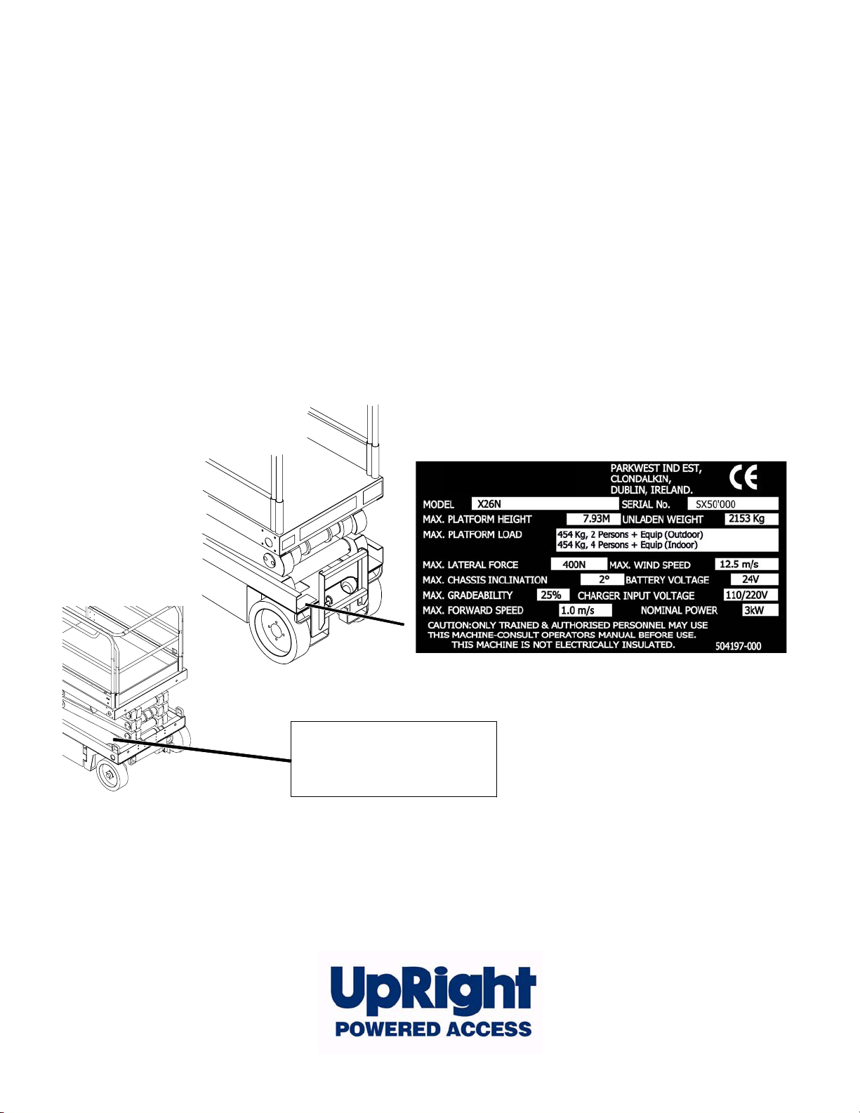
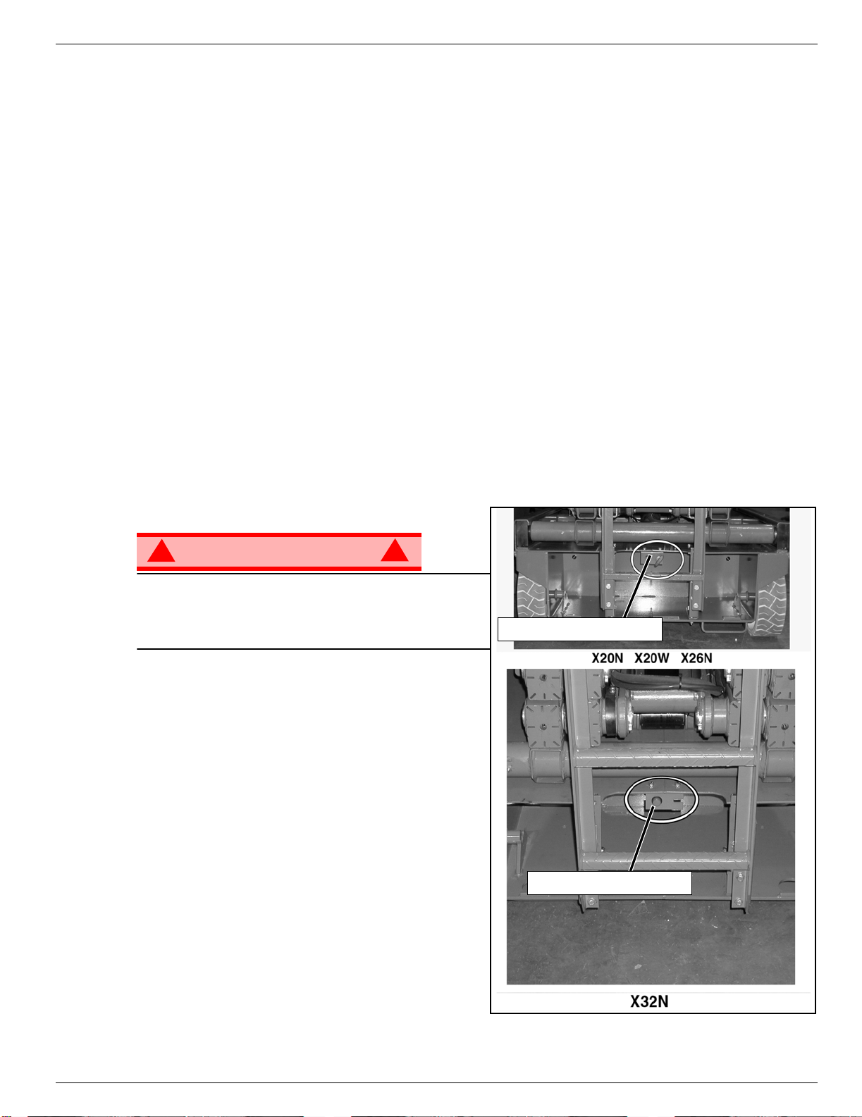
When contacting Ui for service or parts information, be sure to include the MODEL and SERIAL NUMBERS from the equipment nameplate. Should the nameplate be missing, the SERIAL NUMBER is also stamped on top of the chassis above the
front axle pivot.
FRANÇAIS
Lors des communications avec Ui pour des informations au sujet de l’entretient ou des pièces, ne pas oublier d’inclure les
NUMÉROS DE MODÈLE et de SÉRIE inscrits sur la plaque signalétique. Si la plaque signalétique manque, le NUMÉRO
DE SÉRIE est également estampé sur le dessus du châssis, au-dessus de l’axe pivot avant.
DEUTSCH
Stellen Sie sicher, dass Sie die MODELL- und SERIENNUMMERN auf dem Gerätetypenschild angeben, wenn Sie sich mit
Ui bezüglich Wartungs- oder Ersatzteilinformationen in Verbindung setzten. Sollte das Typenschild fehlen, finden Sie die
SERIENNUMMER auch auf dem Fahrwerk über der vorderen Schwenkachse.
Stamped Serial Number
Estampille de numéro de série
Eingestanzte Seriennummer
Page 4
OPERATION MANUAL
C
WA RN IN G
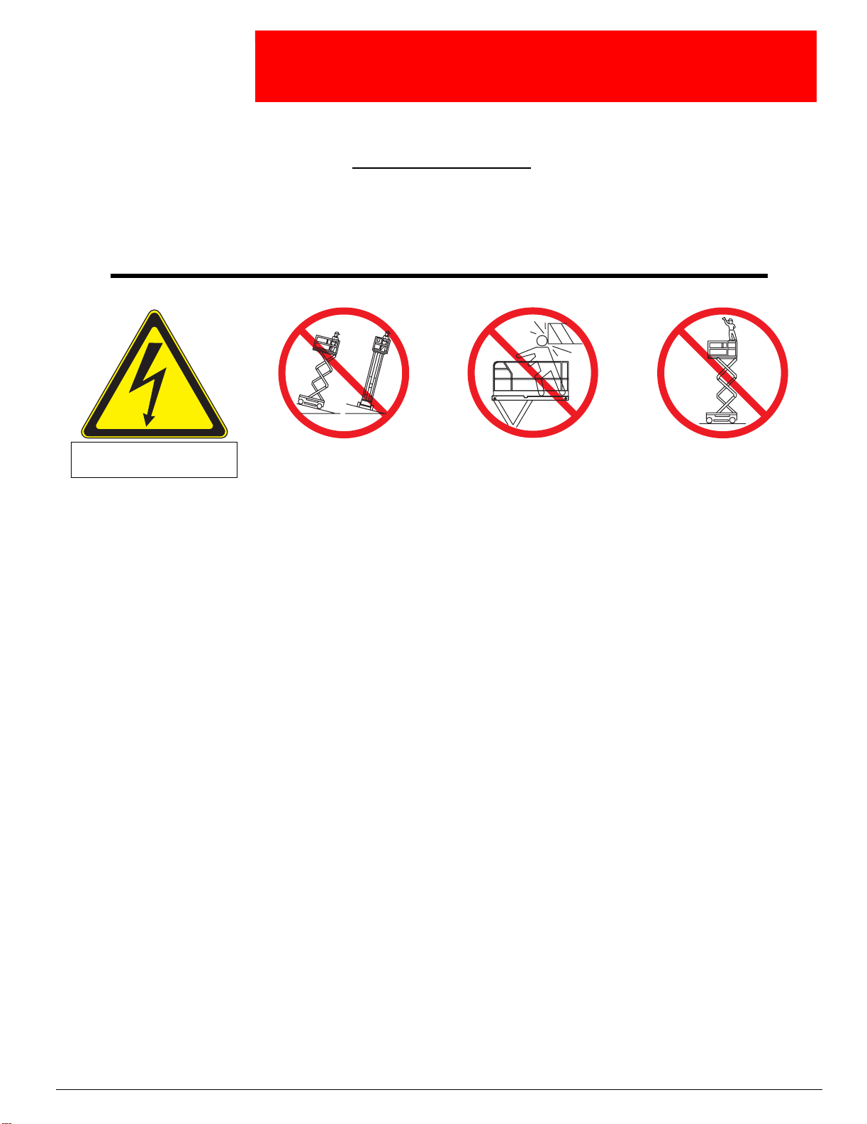
All personnel shall carefully read, understand and follow all safety rules and operating
instructions before operating or performing maintenance on any Ui aerial work platform.
Safety Rules
Electrocution Hazard Tip Over Hazard
THIS MACHINE IS NOT
INSULATED!
USE OF THE AERIAL WORK PLATFORM: This aerial work platform is intended to lift persons and his tools as well as the material
used for the job. It is designed for repair and assembly jobs and assignments at overhead workplaces (ceilings, cranes, roof structures,
buildings etc.). All oth er uses of t he aerial work platform are proh ibited!
THIS AERIAL WORK PLATFORM IS NOT INSULATED! For this reason it is imperative to keep a safe distance from live parts of electrical equipment!
Exceeding the specified permissible maximum load is prohibited! See “Special Limitations” on page 4 for details.
The use and operation of the aerial work platform as a lifting tool or a crane (lifting of loads from below upwards or from up high on
down) is prohibited!
NEVER exceed the manual force allowed for this machine. See “Special Limitations” on page 4 for details.
DISTRIBUTE all platform loads evenly on the platform.
NEVER operate the m achin e withou t first surve y ing th e w ork area f or su rf a ce ha zards such as h oles , dro p-offs , b um ps , curb s, or deb ris;
and avoiding them.
OPERATE machine on ly on surfaces capable of supporting wheel loads.
NEVER operate the machine when wind speeds exceed this machine’s wind rating. See “Beaufort Scale” on page 4 for details.
IN CASE OF EMERGENCY push EMERGENCY STOP switch to deactivate all powered functions.
IF ALARM SOUNDS while platform is elevated, STOP, carefully lower platform. Move machine to a firm, level surface.
Climbing up the r ailing of the pla tf orm, standi ng on o r st epping from th e platform onto buildings , st eel or pref a b conc rete s tructures , etc.,
is prohibited!
Dismantling the swing gate or other railing components is prohibited! Always make certain t hat the swing gate is closed and securely
locked!
It is prohibited to keep the swing gate in an open position (held open with tie-straps) when the platform is raised!
To extend the height or the range by placing of ladders, scaffolds or similar devices on the platform is prohibited!
NEVER perform service on machine while platform is elevated without blocking elevating assembly.
INSPECT the machine thoroughly for cracked welds, loose or missing hardware, hydraulic leaks, l oos e wire connections, and da ma ged
cables or hoses before using.
VERIFY that all labels are in place and legible before using.
NEVER use a machine that is damaged, not functioning properly, or has damaged or missing labels.
To bypass any safety equipment is prohibited and presents a danger for the persons on the aerial work platform and in its working
range.
NEVER charge batteries near sparks or open flame. Charging batteries emit explosive hydrogen gas.
Modifications to the aerial work platform are pr oh ibite d or permissible only at the approval by
AFTER USE, secure the work platform from unauthorized use by turning both keyswitches off and removing key.
NEVER elevate the platform or drive
the machine while elevated unless the
machine is on a firm, level surface.
ollision Hazard Fall Hazard
NEVER position the platform
without first checking for overhead
obstructions or other hazards.
Ui.
NEVER climb, stand, or sit on
platform guardrails or midrail.
Page 1
Page 5

504165-001
C
ONTENTS
Introduction. . . . . . . . . . . . . . . . . . . . . . . . . . . . . . . . . . . . . . . . . . . . . . . . . . . . . . . . . . . . . . . . . . . . . . . . . .3
General Description . . . . . . . . . . . . . . . . . . . . . . . . . . . . . . . . . . . . . . . . . . . . . . . . . . . . . . . . . . . . . . . . . . .3
Special Limitations. . . . . . . . . . . . . . . . . . . . . . . . . . . . . . . . . . . . . . . . . . . . . . . . . . . . . . . . . . . . . . . . . . . .4
Platform Capacity . . . . . . . . . . . . . . . . . . . . . . . . . . . . . . . . . . . . . . . . . . . . . . . . . . . . . . . . . . . . . . . . . . . . . . . . . . . 4
Manual Force . . . . . . . . . . . . . . . . . . . . . . . . . . . . . . . . . . . . . . . . . . . . . . . . . . . . . . . . . . . . . . . . . . . . . . . . . . . . . . 4
Beaufort Scale. . . . . . . . . . . . . . . . . . . . . . . . . . . . . . . . . . . . . . . . . . . . . . . . . . . . . . . . . . . . . . . . . . . . . . . . . . . . . . 4
Lift Overload Alarm . . . . . . . . . . . . . . . . . . . . . . . . . . . . . . . . . . . . . . . . . . . . . . . . . . . . . . . . . . . . . . . . . . . . . . . . . . 4
Controls and Indicators . . . . . . . . . . . . . . . . . . . . . . . . . . . . . . . . . . . . . . . . . . . . . . . . . . . . . . . . . . . . . . . .5
Pre-Operation Safety Inspection . . . . . . . . . . . . . . . . . . . . . . . . . . . . . . . . . . . . . . . . . . . . . . . . . . . . . . . . .6
System Function Inspection . . . . . . . . . . . . . . . . . . . . . . . . . . . . . . . . . . . . . . . . . . . . . . . . . . . . . . . . . . . .7
Operation. . . . . . . . . . . . . . . . . . . . . . . . . . . . . . . . . . . . . . . . . . . . . . . . . . . . . . . . . . . . . . . . . . . . . . . . . . . .8
Platform Extension . . . . . . . . . . . . . . . . . . . . . . . . . . . . . . . . . . . . . . . . . . . . . . . . . . . . . . . . . . . . . . . . . . . . . . . . . . 8
Travel With the Platform Lowered. . . . . . . . . . . . . . . . . . . . . . . . . . . . . . . . . . . . . . . . . . . . . . . . . . . . . . . . . . . . . . . 8
Steering. . . . . . . . . . . . . . . . . . . . . . . . . . . . . . . . . . . . . . . . . . . . . . . . . . . . . . . . . . . . . . . . . . . . . . . . . . . . . . . . . . . 8
Elevating the Platform. . . . . . . . . . . . . . . . . . . . . . . . . . . . . . . . . . . . . . . . . . . . . . . . . . . . . . . . . . . . . . . . . . . . . . . . 8
Travel With the Platform Elevated. . . . . . . . . . . . . . . . . . . . . . . . . . . . . . . . . . . . . . . . . . . . . . . . . . . . . . . . . . . . . . . 9
Lowering the Platform. . . . . . . . . . . . . . . . . . . . . . . . . . . . . . . . . . . . . . . . . . . . . . . . . . . . . . . . . . . . . . . . . . . . . . . . 9
Emergency Lowering. . . . . . . . . . . . . . . . . . . . . . . . . . . . . . . . . . . . . . . . . . . . . . . . . . . . . . . . . . . . . . . . . . . . . . . . . 9
X20N, X20W and X26N. . . . . . . . . . . . . . . . . . . . . . . . . . . . . . . . . . . . . . . . . . . . . . . . . . . . . . . . . . . . . . . . . . . 9
X32N . . . . . . . . . . . . . . . . . . . . . . . . . . . . . . . . . . . . . . . . . . . . . . . . . . . . . . . . . . . . . . . . . . . . . . . . . . . . . . . . . 9
Lower the Guardrails, X26N . . . . . . . . . . . . . . . . . . . . . . . . . . . . . . . . . . . . . . . . . . . . . . . . . . . . . . . . . . . . . . . . . . 10
Lowering Procedure. . . . . . . . . . . . . . . . . . . . . . . . . . . . . . . . . . . . . . . . . . . . . . . . . . . . . . . . . . . . . . . . . . . . . 10
Raising Procedure . . . . . . . . . . . . . . . . . . . . . . . . . . . . . . . . . . . . . . . . . . . . . . . . . . . . . . . . . . . . . . . . . . . . . . 10
Fold Down guardrails, X32N . . . . . . . . . . . . . . . . . . . . . . . . . . . . . . . . . . . . . . . . . . . . . . . . . . . . . . . . . . . . . . . . . . 11
Fold Down Procedure . . . . . . . . . . . . . . . . . . . . . . . . . . . . . . . . . . . . . . . . . . . . . . . . . . . . . . . . . . . . . . . . . . . 11
Erection Procedure . . . . . . . . . . . . . . . . . . . . . . . . . . . . . . . . . . . . . . . . . . . . . . . . . . . . . . . . . . . . . . . . . . . . . 11
Towing or Winching . . . . . . . . . . . . . . . . . . . . . . . . . . . . . . . . . . . . . . . . . . . . . . . . . . . . . . . . . . . . . . . . . .12
Parking Brake Release . . . . . . . . . . . . . . . . . . . . . . . . . . . . . . . . . . . . . . . . . . . . . . . . . . . . . . . . . . . . . . . . . . . . . . 12
After Use Each Day. . . . . . . . . . . . . . . . . . . . . . . . . . . . . . . . . . . . . . . . . . . . . . . . . . . . . . . . . . . . . . . . . . . . . . . . . 12
Hour Meter . . . . . . . . . . . . . . . . . . . . . . . . . . . . . . . . . . . . . . . . . . . . . . . . . . . . . . . . . . . . . . . . . . . . . . . . . . . . . . . 12
Transporting the Work Platform . . . . . . . . . . . . . . . . . . . . . . . . . . . . . . . . . . . . . . . . . . . . . . . . . . . . . . . .13
Preparation for Shipment . . . . . . . . . . . . . . . . . . . . . . . . . . . . . . . . . . . . . . . . . . . . . . . . . . . . . . . . . . . . . . . . . . . . 13
Lifting By Crane. . . . . . . . . . . . . . . . . . . . . . . . . . . . . . . . . . . . . . . . . . . . . . . . . . . . . . . . . . . . . . . . . . . . . . . . . . . . 13
By Forklift . . . . . . . . . . . . . . . . . . . . . . . . . . . . . . . . . . . . . . . . . . . . . . . . . . . . . . . . . . . . . . . . . . . . . . . . . . . . . . . . 13
Driving or Winching onto a Truck or Trailer. . . . . . . . . . . . . . . . . . . . . . . . . . . . . . . . . . . . . . . . . . . . . . . . . . . . . . . 13
Maintenance . . . . . . . . . . . . . . . . . . . . . . . . . . . . . . . . . . . . . . . . . . . . . . . . . . . . . . . . . . . . . . . . . . . . . . . .14
Blocking The Elevating Assembly. . . . . . . . . . . . . . . . . . . . . . . . . . . . . . . . . . . . . . . . . . . . . . . . . . . . . . . . . . . . . . 14
Scissor Brace Installation. . . . . . . . . . . . . . . . . . . . . . . . . . . . . . . . . . . . . . . . . . . . . . . . . . . . . . . . . . . . . . . . . 14
Scissor Brace Stowage . . . . . . . . . . . . . . . . . . . . . . . . . . . . . . . . . . . . . . . . . . . . . . . . . . . . . . . . . . . . . . . . . . 14
Battery Maintenance. . . . . . . . . . . . . . . . . . . . . . . . . . . . . . . . . . . . . . . . . . . . . . . . . . . . . . . . . . . . . . . . . . . . . . . . 15
Battery Charging . . . . . . . . . . . . . . . . . . . . . . . . . . . . . . . . . . . . . . . . . . . . . . . . . . . . . . . . . . . . . . . . . . . . . . . 15
Inspection and Maintenance Schedule. . . . . . . . . . . . . . . . . . . . . . . . . . . . . . . . . . . . . . . . . . . . . . . . . . .16
Daily Preventative Maintenance Checklist. . . . . . . . . . . . . . . . . . . . . . . . . . . . . . . . . . . . . . . . . . . . . . . .16
Labels . . . . . . . . . . . . . . . . . . . . . . . . . . . . . . . . . . . . . . . . . . . . . . . . . . . . . . . . . . . . . . . . . . . . . . . . . . . . .17
Specifications . . . . . . . . . . . . . . . . . . . . . . . . . . . . . . . . . . . . . . . . . . . . . . . . . . . . . . . . . . . . . . . . . . . . . . .19
Page 2 Operation Manual
Page 6
Introduction 504165-001
I
NTRODUCTION
This manual covers operation of the X Series Self-Propelled Work Platforms. This manual must be
stored on the machine at all times.
G
ENERAL
D
ESCRIPTION
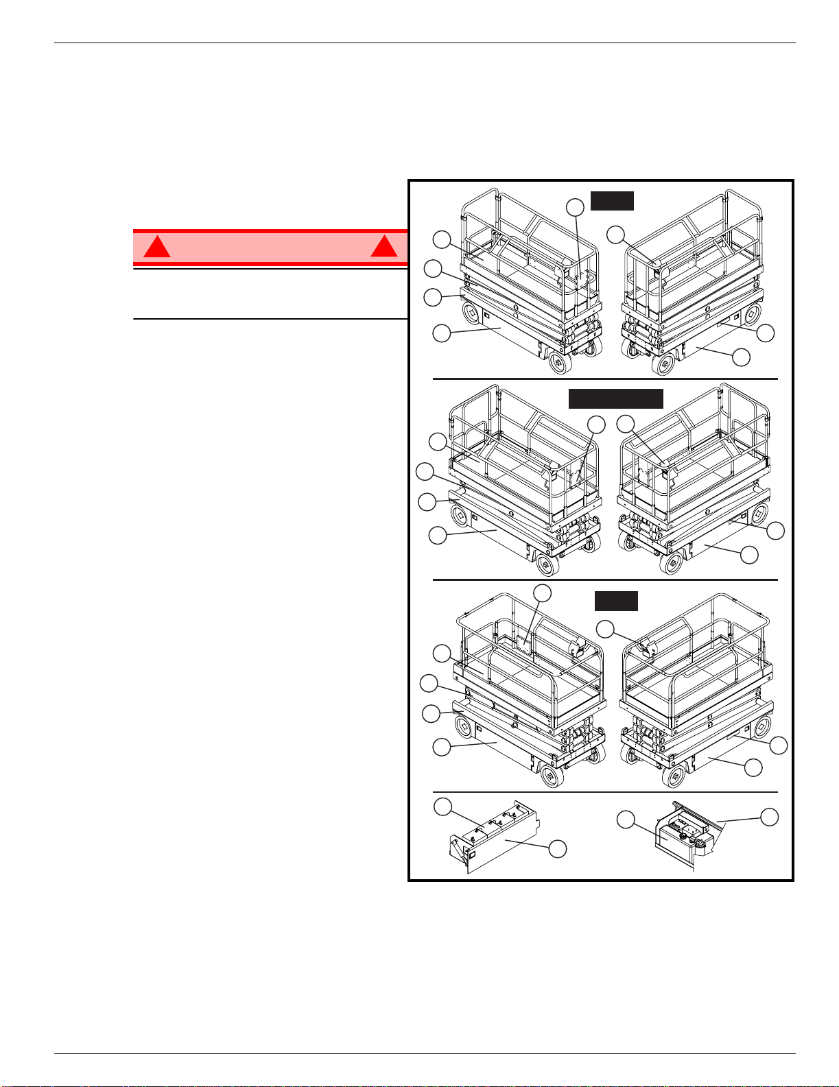
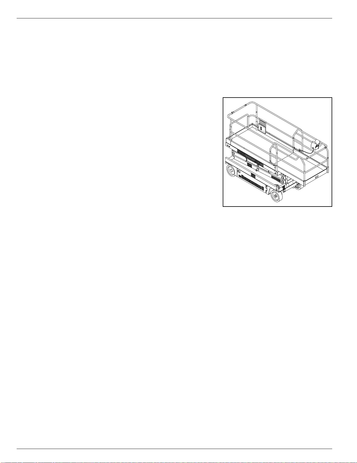
1. Platform
7
Figure 1: X Series
X20N
!
WARNING
DO NOT use the maintenance platform
without guardrails properly assembled
and in place
2. Elevating Assembly
3. Chassis
4. Power Module
5. Control Module
6. Platform Controls
7. Manual Case
8. Chassis Controls
9. Hydraulic Fluid Reservoir
10. Batteries
1
6
!
2
3
4
X20W & X26N
6
7
1
2
3
4
7
X32N
6
8
5
8
5
1
2
3
4
10
9
4
8
5
5
Operation Manual Page 3
Page 7
504165-001 Special Limitations
S
PECIAL
L
IMITATIONS
Travel with the platform raised is limited to creep speed range.
Elevating the Work Platform is limited to firm, level surfaces only.
DANGER
! !
The elevating function shall ONLY be used when the work platform is level and on a firm surface.
The work platform is NOT intended to be driven over uneven, rough, or soft terrain.
P
LATFORM
The maximum capacity for the MACHINE, including occupants is determined by model and options, and
is listed in “Specifications” on page 20.
DANGER
! !
DO NOT exceed the maximum platform capacity or the platform occupancy limits for this machine.
M
ANUAL
Manual force is the force applied by the occupants to objects such as walls or other structures outside the
work platform.
F
C
APACITY
ORCE
The maximum allowable manual force is limited to 200 N (45 lbs.) of force per occupant, with a maximum
of 400 N (90 lbs.) for two or more occupants.
DANGER
! !
DO NOT exceed the maximum amount of manual force for this machine.
B
EAUFORT
Never operate the machine when wind speeds exceed 25 km/h (15 mph) [Beaufort scale 4].
BEAUFORT
RATING
3 3,4~5,4 12,25~19,4 11.5~17.75 7.5~12.0 Papers and thin branches move, flags wave.
4 5,4~8,0 19,4~28,8 17.75~26.25 12.0~18 Dust is raised, paper whirls up, and small branches sway.
5 8,0~10,8 28,8~38,9 26.25~35.5 18~24.25 Shrubs with leaves start swaying. Wave crests are apparent in ponds or swamps.
6 10,8~13,9 38,9~50,0 35.5~45.5 24.5~31 Tree branches move. Power lines whistle. It is difficult to open an umbrella.
7 13,9~17,2 50,0~61,9 45.5~56.5 31.~38.5 Whole trees sway. It is difficult to walk against the wind.
m/s km/h ft/s mph
L
IFT
O
If a load equivelent to 90% of safe working load is lifted a fault code “03” will be displayed on the digital
display on the platform control box. If a load which is greater than the safe working load is present in the
basket all machine functions will cease to operate and an acoustic warning will sound. In order to return to
normal operation a load equal to or less than the safe working load must be present in the basket and the
power must be re-cycled, power can be re-cycled by pushing the emergency stop button and releasing it
again.
S
CALE
WIND SPEED
VERLOAD
A
GROUND CONDITIONS
LARM
DANGER
! !
Never operate the machine with a platform load greater than the rated capacity.
Page 4 Operation Manual
Page 8

Controls and Indicators 504165-001
C
ONTROLS AND INDICATORS
Figure 2: Controls and Indicators
Platform Controls
4
6
3
1
1 Drive Selectors
2. Horn Button
3. Lift/Lower Button
4. Emergency Stop Button
5. Display
6. Joystick
1
2
Chassis Controls
2
5
34
1. Keyswitch
2. Enable Button
3. Toggle Switch (Up & Down)
4. Emergency Stop Switc h
Operation Manual Page 5
Page 9
504165-001 Pre-Operation Safety Inspection
P
RE
-O
PERATION
NOTE: Carefully read, understand and follow all safety rules, operating instructions, labels and National Safety
Instructions/Requirements. Perform the following steps each day before use.
1. Open modules and inspect for damage, fluid leaks or missing parts.
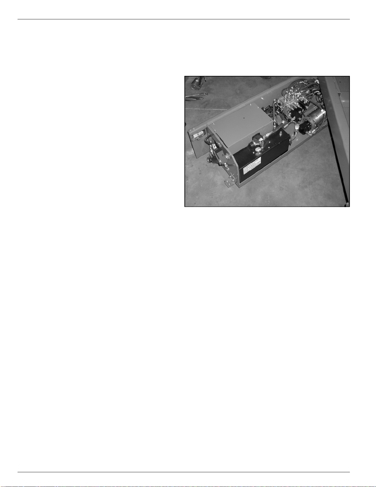
2. Check the level of the hydraulic fluid with
the platform fully lowered. The hydraulic
reservoir is located in the Control Module Door. The fluid level must be
between the MIN and MAX lines. Add
hydraulic fluid if necessary.
3. Check that fluid level in the batteries is
correct.
4. Verify that batteries are charged.
5. Check that A.C. extension cord has
been disconnected from the plug in the
rear of the machine.
6. Check that all guardrails are in place
and all fasteners are properly tightened.
7. Inspect the machine thoroughly for
cracked welds and structural damage,
loose or missing hardware, hydraulic
leaks, damaged control cable, loose wire connections and wheel bolts.
S
AFETY
I
NSPECTION
Figure 3: Hydraulic Tank
Page 6 Operation Manual
Page 10

System Function Inspection 504165-001
S
YSTEM
F
UNCTION INSPECTION
Refer to Figure 2 for the locations of various controls and indicators.
!
WARNING
STAND CLEAR of the work platform while performing the following checks.
Before operating the work platform, survey the work area for surface hazards such as holes, drop-offs,
bumps and debris.
Check in ALL directions, including above the work platform, for obstructions and electrical conductors.
Protect the control console cable from possible damage while performing checks.
1. Move the machine, if necessary, to an unobstructed area to allow for full elevation.
2. Pull Chassis Emergency Stop Switch to the ON position.
3. Pull Platform Emergency Stop Switch to the ON position.
4. Turn and hold the Chassis Key Switch to the ON position. Push the Chassis Lift/Lower Switch to the UP
position and raise the platform approximately 2,1 m (7 feet). BLOCK THE ELEV ATING ASSEMBLY AS
DESCRIBED ON PAGE 9.
5. Visually inspect the elevating assembly, lift cylinder, cables, and hoses for cracked welds and structural
damage, loose hardware, hydraulic leaks, loose wire connections, and erratic operation. Check for missing or loose parts.
6. Verify that the Depression Mechanism Supports have rotated into position under the machine. REMOVE
THE SCISSOR BRACE AS DESCRIBED ON page 14.
7. Push the Chassis Lift/Lower Switch to the UP position and fully elevate the platform.
8. Partially lower the platform by pushing Chassis Lift/Lower Switch to LOWER, and check for proper operation of the audible lowering alarm.
9. Open the Emergency Lowering Valve (see Figure 5) by pulling the knob out to check for proper operation. When the platform is lowered, release the knob.
10. Push the Chassis Emergency Stop Switch to check for proper operation. All machine functions should
be disabled. Pull out the Chassis Emergency Stop Switch to resume.
11. Check that the route is clear of obstacles (persons, obstructions, holes, and drop-offs, bumps and
debris), is level, and is capable of supporting the wheel loads.
12. Mount the platform and properly close the entrance.
13. Mount the platform and select DRIVE mode.
!
NOTE: Use both HI and LOW drive (if applicable) when performing the following step.
14. While engaging the Interlock Switch, move the Control Handle to FORWARD, then REVERSE, to check
for speed control.
15. Push the Steering Switch RIGHT, then LEFT, to check for steering control.
16. Select LIFT mode. Grasp the Control Handle, engaging the Interlock Switch, and push it forward to
check platform lift controls. Raise the platform to full elevation.
17. Pull back on the Control Handle. The platform should descend and the audible lowering alarm should
sound.
18. Push the Platform Emergency Stop Switch to check for proper operation. All machine functions should
be disabled. Pull out the Platform Emergency Stop Switch to resume.
Operation Manual Page 7
Page 11
504165-001
O
PERATION
Before operating the work platform, ensure that the Pre-Operation Safety Inspection has been completed
and that any deficiencies have been corrected. Never operate a damaged or malfunctioning machine.
The operator must be thoroughly trained on this machine.
P
LATFORM
1. Mount the platform and properly close the entrance.
2. Depress the foot lever located at the rear of the platform
extension. Push the platform extension forward until the
pin engages the front stop.
3. To retract the platform extension, depress the foot lever
and pull the platform extension toward the rear of the
machine until the pin engages the rear stop.
T
RAVEL
OWERED
L
1. Check that the route is clear of obstacles (persons,
obstructions, holes, drop-offs, bumps, and debris), is level,
and is capable of supporting the wheel loads.
2. Verify that the Chassis Key Switch is turned to ON and the
Chassis Emergency Stop Switch is ON (pulled out).
3. Mount the platform and properly close the entrance.
4. Check clearances above, b elow, and to the sides of platform.
5. Pull the Platform Emergency Stop Switch out to the ON position.
6. Select DRIVE mode.
E
W
ITH THE
XTENSION
P
LATFORM
Figure 4: Platform Extension
NOTE: Choose between standard drive and extra torque depending on the gradient.
7. Engage the Interlock Switch and move the Control Handle to FORWARD or REVERSE to travel in the
desired direction. The speed of the machine will vary depending on how far from center the Control
Handle is moved.
S
TEERING
1. Turn the Drive/Lift Switch to DRIVE.
2. While engaging the Interlock Switch, push the Steering Switch to RIGHT or LEFT to turn the wheels in
the desired direction. Observe the tires while maneuvering the work platform to ensure proper direction.
NOTE: Steering is not self-centering. Wheels must be returned to the straight ahead position by operating the Steering
Switch.
E
LEVATING THE
1. Select a firm, level surface.
2. Select LIFT mode.
3. While engaging the Interlock Switch, push the Control Handle forward.
4. If the machine is not level the tilt alarm will sound and the machine will not lift or drive. If the tilt alarm
sounds the platform must be lowered and the machine moved to a firm level surface before
attempting to re-elevate the platform.
NOTE: Depression Mechanism supports will deploy automatically as the platform elevates and will retract after the
platform has been lowered completely and has been driven.
P
LATFORM
Page 8 Operation Manual
Page 12
Operation 504165-001
T
RAVEL
NOTE: The machine will travel at reduced speed when the platform is elevated.
1. Check that the route is clear of obstacles (persons, obstructions, holes, drop-offs, bumps, and debris), is
level, and is capable of supporting the wheel loads.
2. Check clearances above, b elow, and to the sides of platform.
3. Select DRIVe mode.
4. Engage the Interlock Switch and move the Control Handle to FORWARD or REVERSE to travel in the
desired direction. The speed of the machine will vary depending on how far from center the Control Handle is moved.
5. If the machine is not level the tilt alarm will sound and the machine will not lift or drive. If the tilt alarm
sounds the platform must be lowered and the machine moved to a firm, level surface before
attempting to re-elevate the platform.
L
OWERING THE
1. Select LIFT mode.
2. Check around the base of the platform to ensure that no one is in contact with the machine. Engage the
Interlock Switch and pull back on the Control Handle to lower the platform.
3. The platform will stop when it reaches the PPE cutout height. Inspect around the machine to ensure no
one is in contact with the machine. After a four-second time delay, lower the platform as in step 2.
W
ITH THE
P
P
LATFORM
LATFORM
E
LEVATED
E
MERGENCY
!
WARNING
If the platform should fail to lower, NEVER climb
down the elevating assembly.
Stand clear of the elevating assembly while operating
the Emergency Lowering Valve Knob.
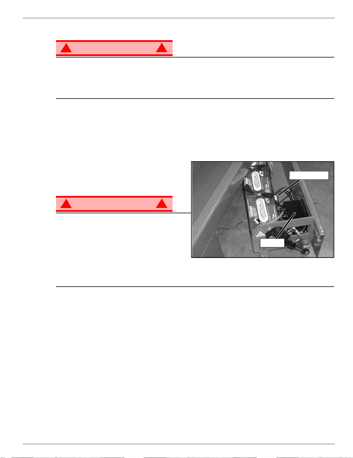
X20N, X20W
The Emergency Lowering Valve for the X20N,
X20W, and X26N is located at the rear of the
machine, above the charger.
1. Open the Emergency Lowering Valve by pulling
and holding the knob.
2. To close, release the knob. The platform will not
elevate if the Emergency Lowering Valve is open.
L
OWERING
AND
X26N
!
X32N
The emergency lowering control switch is located at
the rear of the machine.
Figure 5: Emergency Lowering Valve
Emergency Lowering Knob
Emergency Lowe r i ng Button
1. Open the emergency lowering valve by pushing
down on the toggle switch and holding it.
2. Once the platform is fully lowered, release the
toggle switch to close the valve. The platform will
not elevate if the Emergency Lowering Valve is
open.
Operation Manual Page 9
Page 13

504165-001 Operation
L
OWER THE
This procedure applies only to the X26N model for the purpose of passing through a standard double
doorway. Guardrails must be returned to proper position before using the machine.
L
OWERING PROCEDURE
1. Ensure that the slide-out deck extension is fully retracted and the deck pin is locked. Place the Platform
Control s on the floor of the platform.
2. Remove and retain the set screws from the side guardrails and the slide-out deck guardrails.
3. Lower the slide-out deck guardrail completely.
4. Lower the rear guardrail until it rests on the stop screws.
5. Lower the side guardrails completely.
6. Raise the rear guardrail until the retaining pins engage. Remove and retain the stop screws and nuts
from the rear guardrail.
7. Pull the two retaining pins and lower the rear guardrail completely.
R
AISING PROCEDURE
1. Raise the rear guardrail until the retaining pins engage.
2. Install the stop screws and nuts on the rear guardrail and torque to 42 N-m (31 ft. lbs).
3. Pull the two retaining pins and lower the rear guardrail until it rests on the stop screws.
4. Raise the side guardrails until the tops are level with the rear guardrail.
• Install the set screws
5. Raise the slide-out deck guardrail until the top is level with the side guardrails.
• Install the set screws
6. Hang the controller on the slide-out deck guardrail.
7. Torque all set screws to 42 N-m (31 ft. lbs).
G
UARDRAILS
, X26N
!
WARNING
Before operating machine, guardrails must be securely fastened in their proper position.
!
Page 10 Operation Manual
Page 14

Operation 504165-001
F
OLD
F
OLD
1. Unhook the controller from the side guardrail and place it on the floor of the platform.
2. Pull the retaining pin on the front guardrail and rotate inwards.
3. Pull the retaining pin on the rear guardrail and rotate inwards.
4. Starting with the slide-out deck guardrails and then the outer guardrails, lift up on each guardrail and fold
E
RECTION
1. Starting with the outer guardrails and then the slide-out deck guardrails, raise each guardrail and drop it
2. Rotate the front and rear upper guardrails outward and secure them to the opposite side guardrails,
3. Hang the controller on the side guardrail.
D
OWN GUARDRAILS
This procedure applies only to the X32N model for the purpose of passing through a standard double doorway. Guardrails must be returned to proper position before using the machine.
D
OWN PROCEDURE
inward.
P
ROCEDURE
down, securing it in the vertical position.
using the retaining pins.
, X32N
Operation Manual Page 11
Page 15

504165-001 Towing or Winching
T
OWING OR
W
INCHING
Perf orm the following only when the machine will not operate under its own power and it is necessary to
move the machine or when winching onto a transport vehicle (see “Transporting the Work Platform” on
page 13).
CAUTION
DO NOT tow or winch the machine faster than 0,3 m/s (1 ft./s). Faster speeds will damage drive
components and void the warranty.
!
WARNING
Never tow faster than 0,3 m/sec. (1 ft./sec.).
Never operate the work platform with the parking brakes released. Serious injury or damage could
result.
A
FTER
1. Ensure that the platform is fully lowered.
2. Park the machine on a firm level surface, preferably under cover, secure against vandals, children and
3. Turn the Chassis Key Switch to OFF and remove the key to prevent unauthorized operation.
H
OUR
To access the hour meter function perform the following steps.
1. Climb into the basket (with the machine powered up)
2. Push the platform emergency stop button.
3. Hold down the following buttons, Jib and Upper Boom Lift.
4. While holding the buttons twist the emergency stop button to return power to the machine.
5. “hr” will now be displayed on the readout, Pressing the right turn button will scroll through the accumulated hours two digits at a time. For example, if pressing the right turn button once displays “20”, pressing
it a 2nd time displays “58”, and pressing it a 3rd time displays “hr”, the elapsed time of operation is 2058
hours.
U
SE
E
ACH
unauthorized operation.
M
ETER
D
!
AY
Page 12 Operation Manual
Page 16
Transporting the Work Platform 504165-001
T
RANSPORTING THE
P
REPARATION FOR
1. Fully lower the platform.
2. Disconnect the battery negative (-) lead from the battery terminal.
3. Band the controller to the front guardrail.
4. Band the elevating linkage to the frame.
L
IFTING
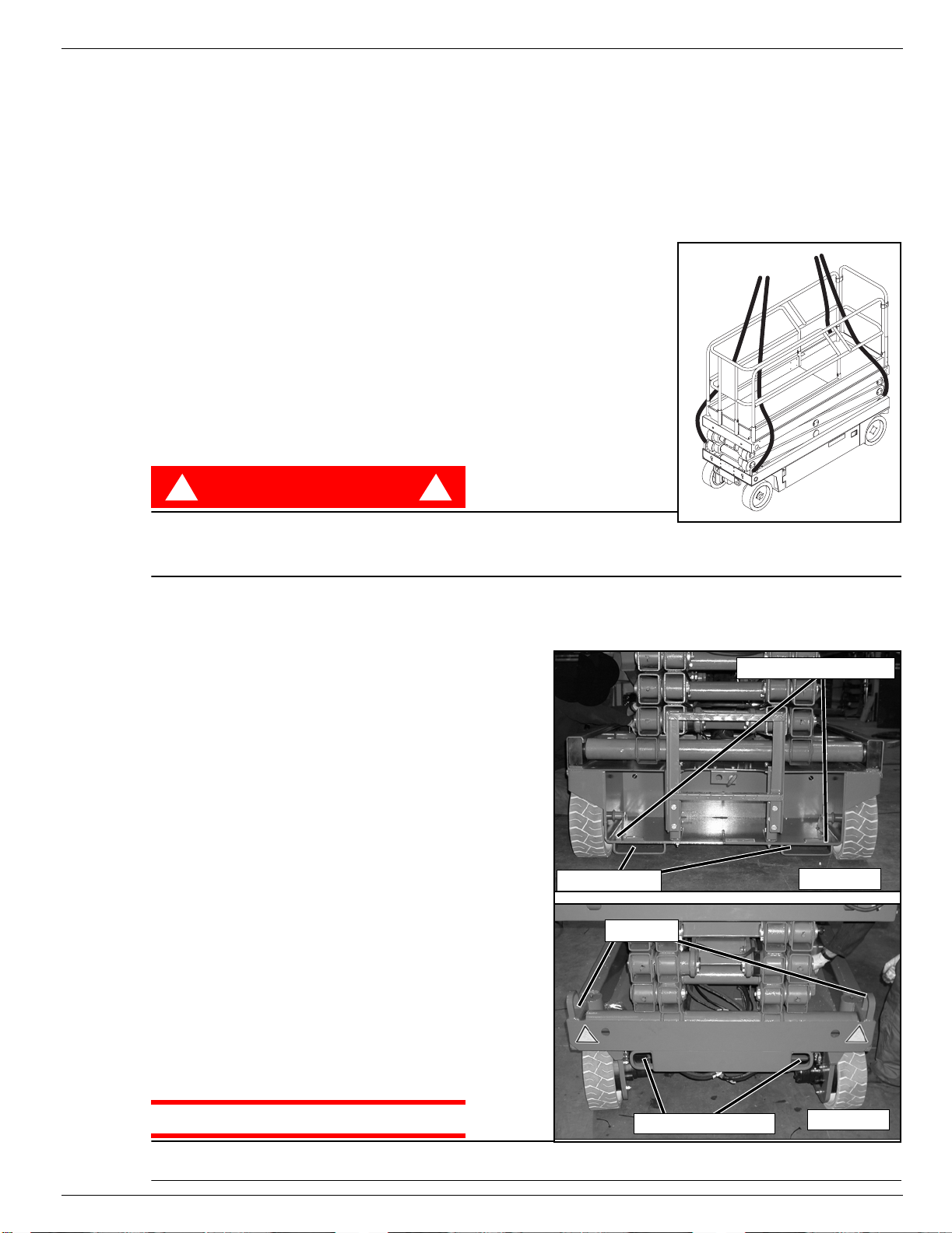
1. Secure straps to chassis tie down/lifting lugs only.
2. Place the platform onto the transport vehicle in transport position.
3. Chock the wheels.
4. Secure the work platform to the transport vehicle with chains or straps
of adequate load capacity attached to the chassis tie down/lifting lugs.
BY C
W
ORK
RANE
P
S
HIPMENT
LATFORM
Figure 6: Secure Crane Straps
BY F
Forklifting is for transport only.
See specifications for weight of work platform and be certain that forklift is of adequate capacity to lift
the work platform.
D
RUCK OR
T
NOTE: Do not winch faster than 0,3 m/s (1 ft/s).
1. Move the machine onto the truck or trailer;
2. Secure the work platform to the transport vehicle
ORKLIFT
DANGER
! !
Forklift from the rear of the machine using the forklift pockets provided. If necessary, the machine may be
forklifted from the side by lifting under the Chassis Modules.
Figure 7: Transporting the Work Platform
RIVING OR
A. To Drive the machine onto the transport vehicle:
a. Move the work platform up the ramp and into
transport position.
b. Set the wheels straight and turn off the machine.
c. Chock the wheels.
B. To Winch the machine onto the transport vehicle:
a. Move the work platform up to the ramp.
b. Attach the winch cable to the tie down/lifting lugs.
c. Release the parking brakes (refer to “Towing or
Winching” on page 12).
d. Winch the platform into transport position
e. Chock the wheels.
with chains or straps of adequate load capacity
attached to the chassis tie down/lifting lugs.
W
T
RAILER
INCHING ONTO A
Forklift Pockets
Lift Lugs
Rear Tie Down/Lift Lugs
REAR
CAUTION
Overtightening of the chains or straps attached to the
Tie Down/Lifting Lugs may result in damage to work platform.
Operation Manual Page 13
Front Tie Down Lugs
FRONT
Page 17
504165-001 Maintenance
M
AINTENANCE
!
WARNING
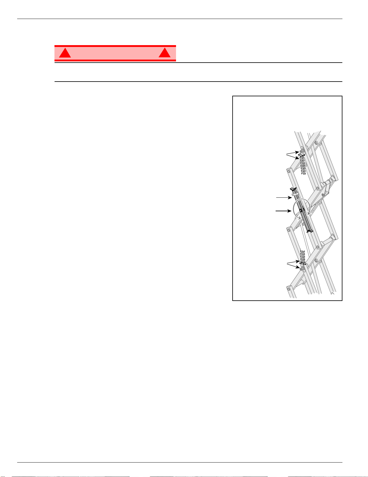
Never perform service while the platform is elevated without first blocking the elevating assembly.
DO NOT stand in the elevating assembly area while deploying or storing the brace.
B
LOCKING
SSEMBLY
A
S
CISSOR BRACE INSTALLATION
1. Park the work platform on a firm, level surface.
2. Pull Chassis EMERGENCY STOP Switch to the ON position.
3. Pull Platform EMERGENCY STOP Switch to the ON position.
4. Turn and hold the Chassis Key Switch to CHASSIS.
5. Push the Chassis Lift/Lower Switch to LIFT to elevate the
platform until the Scissor Brace can be rotated to the vertical
position.
6. X20N, X20W, and X26N – From the rear of the machine, lift
the Scissor Brace from its stowed position. Rotate upward
and outward, then down until it is hanging vertically below its
attachment point.
7. X32N – From the left side of the machine, pull the locking
pin securing the brace. Rotate the Scissor Brace counterclockwise until it is in the vertical posit ion .
8. Lower the platform by pushing the Chassis Lift/Lower Switch
to LOWER and gradually lower the platform until the Scissor
Brace is supporting the platform.
T
HE
E
LEVATING
!
Figure 8: Scissor Brace
X20N, X20W, and X26N
Pin Rests on Brace
when in Blocking
Position
Scissor Brace in
Rest Position
Brace Rotates to
Blocking Position
Brace Rests on Pin
when in Blocking
Position
X32N
S
CISSOR BRACE
1. Using the Chassis Controls, gradually elevate the platform until the Scissor Brace is clear.
2. X20N, X20W, and X26N – Rotate the Scissor Brace outward and upward over its mounting point until it
rests in the stowed position.
3. X32N – Rotate the Scissor Brace clockwise until the locking pin engages.
4. Lower the platform by pushing the Chassis Lift/Lower Switch to LOWER to completely lower the platform.
Page 14 Operation Manual
S
TOWAGE
Page 18
Maintenance 504165-001
B
ATTERY
M
AINTENANCE
!
WARNING
Hazard of explosive gas mixture. Keep sparks, flame, and smoking material away from batteries.
Always wear safety glasses when working near batteries.
Battery fluid is highly corrosive. Thoroughly rinse away any spilled fluid with clean water.
Always replace batteries with Ui batteries or manufacturer approved replacements weighing 26,3 kg
(58 lbs.) each.
• Check the battery fluid level daily, especially if the work platform is being used in a warm, dry climate.
• If electrolyte level is lower than 10 mm
tap water with high mineral content, as it will shorten battery life.
• Keep the terminals and tops of the batteries clean.
• Refer to the Service Manual to extend battery life and for complete service instructions.
B
ATTERY CHARGING
Charge the batteries at the end of each work
shift or sooner if the batteries have been discharged.
!
WARNING
Charge the batteries in a well ventilated area.
Do not charge the batteries when the work
platform is near a source of sparks or flames.
Permanent damage to the batteries will result if
the batteries are not immediately recharged after
discharging.
Never leave the battery charger operating for more than two days.
Never disconnect the cables from the batteries when the charger is operating.
Keep the charger dry.
!
3
(
/
in.) above the plates add distilled water only. DO NOT use
8
Figure 9: Battery Charger
Charger Plug
!
Charger
3
(
/
1. Check the battery fluid level. If the battery fluid level is lower than 10 mm
distilled water only.
2. Connect an appropriate extension cord to charger outlet plug in Left Module Door. Plug the extension
cord into a properly grounded outlet of proper voltage and frequency.
3. The charger turns on automatically after a short delay. The LED charge indicator will illuminate. After
completion of the charge cycle the LED will blink, indicating that the charger is in a continuing maintenance mode. DO NOT leave the charger plugged in for more than 48 hours, as permanent damage to
the batteries may occur.
NOTE: The battery charger circuit must be used with a GFI (Ground Fault Interrupt) outlet.
NOTE: DO NOT operate the machine while the charger is plugged in.
Operation Manual Page 15
in.) above the plates add
8
Page 19
504165-001 Inspection and Maintenance Schedule
I
NSPECTION AND
M
AINTENANCE
S
CHEDULE
The Complete Inspection consists of periodic visual and operational checks, along with periodic minor
adjustments that assure proper performance. Daily inspection will prevent abnormal wear and prolong the
life of all systems. The inspection and maintenance schedule should be performed at the specified intervals. Inspection and maintenance shall be performed by personnel who are trained and familiar with
mechanical and electrical procedures.
D
AILY
M
AINTENANCE
!
WARNING
Before performing preventative maintenance, familiarize yourself with the operation of the machine.
Always block the elevating assembly whenever it is necessary to perform maintenance while the
platform is elevated.
The daily preventative maintenance checklist has been designed for machine service and maintenance.
Please photocopy this page and use the checklist when inspecting the machine.
P
REVENTATIVE
T
ABLE KEY
Y = Yes/Acceptable
N = No/Not Acceptable
R = Repaired/Acceptable
!
M
AINTENANCE
C
HECKLIST
P
REVENTATIVE MAINTENANCE
R
EPORT
Date:_______________________________________
Owner: _____________________________________
Model No:___________________________________
Serial No: ___________________________________
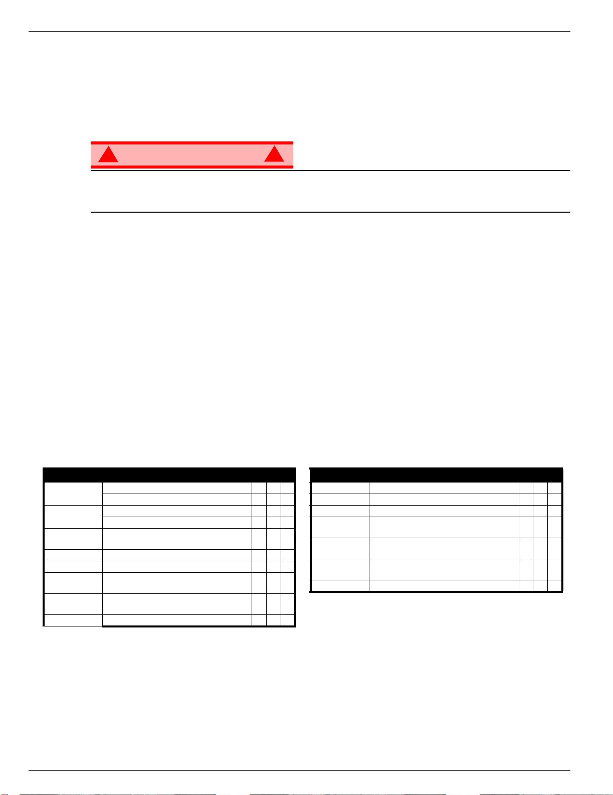
COMPONENT INSPECTION OR SERVICES Y N R
Battery
Chassis
Control Cable
Controller Check switch operation.
Drive Motors Check for operation and leaks.
Elevating
Assembly
Emergency
Lowering System
Entire Unit Check for and repair collision damage.
Check electrolyte level.
Check battery cable condition.
Check hoses for pinch or rubbing points.
Check welds for cracks.
Check the exterior of the cable for pinching,
binding or wear.
Inspect for structural cracks.
Operate the emergency lowering valve and check
for serviceability.
Serviced By:_________________________________
COMPONENT INSPECTION OR SERVICES Y N R
Hydraulic Fluid Check fluid level.
Hydraulic Pump Check for hose fitting leaks.
Hydraulic System Check for leaks.
Labels
Platform Deck
and Rails
Platform Deck
and Rails
Tyres and Wheels Check for damage.
Check for peeling, missing, or unreadable labels
& replace.
Check welds for cracks.
Check condition of deck.
Page 16 Operation Manual
Page 20

Daily Preventative Maintenance Checklist 504165-001
N
OTES
:
Operation Manual Page 17
Page 21
504165-001 Labels
MAX = 113 kg =
066561-902
067195-001
454Kg,2Persons+Equip(Outdoor)
CLONDALKIN,
DUBLIN,IRELAND.
PARKWESTINDEST,
THISMACHINECONSULTOPERATORSMANUALBEFOREUSE.
CAUTION:ONLYTRAINED&AUTHORISEDPERSONNELMAYUSE
CHARGERINPUTVOLTAGE
MAX.WINDSPEED
UNLADENWEIGHT
SERIALNo.
UpRight
MAX.CHASSISINCLINATION
MAX.LATERALFORCE
MAX.PLATFORMLOAD
MAX.PLATFORMHEIGHT
NOMINALPOWER
MODEL
X26N
400N
3kW
2∞
5.8m
110/220V
12.5m/s
BATTERYVOLTAGE
24V
2153Kg
MAX.GRADEABILITY
MAX.FORWARDSPEED
1.0m/s
25%
504197000
454Kg,4Persons+Equip(Indoor)
L
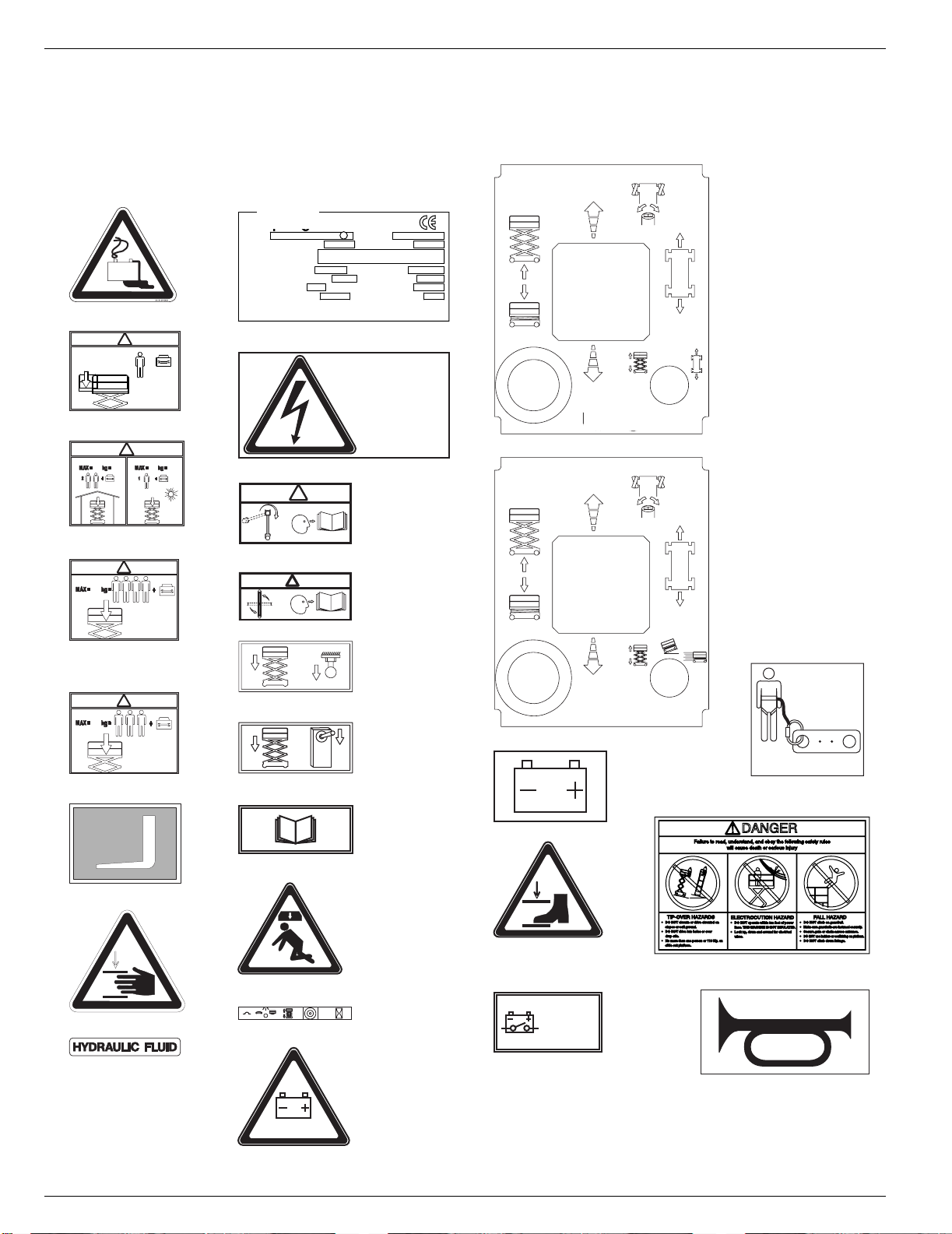
ABELS
These labels shall be present and in good condition before operating the work platform. Be sure to read,
understand and follow these labels when operating the work platform.
11 504197-000
15 100102-900
THIS PLATFORM IS
NOT INSULATED
DIESE ARBEITSBÜHNE
IST NICHT ISOLIERT
CETTE PLATEFORME
N'EST ISOLEE
100102-900
31 X20N 101222-904
4 101210-000
!
1
MAX = 113 kg =
+
5 066551-950
!
340
340
066551-950
!
066557-951
066557-930
6 X20N 066557-930
!
454
066557-951
066557-954
16 X20N, 20W, 26N 066561-900
!
16 X32N 066561-902
066561-900
066561-902
6 X20W, 26N
066557-957
!
340
17 X20N, 20W, 26N 005223-906
005223-906
31 X20W, 26N, 32N 101222-905
066557-951
066557-950
6 X32N 066557-950
17 X32N 005223-908
005223-908
36 068635-001
066522-900
32 066522-900
010076-901
014222-903
20 010076
7 014222-903
33 501453-000
37 067195-001
25 066556-900
9 503724-000
10 060197-001
26 503721-000
INSIDE
INNSEITIG
L'INTERIEUR
107051-900
34 503723-000
40 107053-000
26,3 kg +
29 062562-951
Page 18 Operation Manual
Page 22

Labels 504165-001
Operation Manual Page 19
Page 23

504165-001 Specifications
S
PECIFICATIONS
ITEM X20N X20W X26N X32N
Platform Size w/ Extension
Max. Platform Capacity
Standard 340 kg [750 lbs.] 454 kg [1000 lbs.] 454 kg [1000 lbs.] 340 kg [750 lbs.]
on Extension 110 kg [250 lbs.] 113 kg [250 lbs.] 113 kg [250 lbs.] 113 kg [250 lbs.]
Max. No. of occupants
Standard (total) 3 people indoor
on Extension 1 person 1 person 1 person 1 person
Height
Working Height 8.1 m [26.58 ft.] 8.1 m [26.58 ft.] 9.93 m [32.58 ft.] 11.6 m [38.1 ft.]
Max. Platform Height 6.1 m [20 ft.] 6.1 m [20 ft.] 7.93 m [26 ft.] 9.75 m [32 ft.]
Min. Platform Height 0.96 m [38 in.] 0.96 m [38 in.] 1.09 m [43 in.] 1.22 m [48 in.]
Dimensions
Weight 1736 kg [3828 lbs.] 1938 kg [4273 lbs.] 2153 kg [4747 lbs.] 2486 kg [5481 lbs.]
Overall Width 0.82 m [32.5 in.] 1.22 m [48 in.] 1.22 m [48 in.] 1.22 m [48 in.]
Overall Height 2.06 m [78.5 in.] 2.06 m [78.5 in.] 2.19 m [83.5 in.] 2.32 m [88.5 in.]
Overall Height, Rails Lowered N/A N/A 1.98 m [78 in.] 1.88 m [74 in.]
Overall Length, Extension In 2.35 m [92.5 in.] 2.35 m [92.5 in.] 2.35 m [92.5 in.] 2.35 m [92.5 in.]
Overall Length, Extension Out 3.26 m [128.5 in.] 3.26 m [128.5 in.] 3.26 m [128.5 in.] 3.26 m [128.5 in.]
Drivable Height 6.1 m [20 ft.] 6.1 m [20 ft.] 7.93 m [26 ft.] 9.75 m [32 ft.]
Drive Speed
Platform Lowered 0 to 3,2 km/h [0 to 2.0 mph]
Platform Raised 0 to 1 km/h [0 to 0.62 mph]
Energy Source 24 Volt Battery Pack (4-220 A Hour, 6 Volt Batteries, min. wt. 28.12 kg [62 lbs.] each)
Motor 24 Volt 4 Horse Power DC Electric Motor
System Voltage 24 Volt DC
Battery Charger 25 A, 110/220 V AC
Battery Duty Cycle 25% for 8 Hours
Hydraulic Tank Capacity 15 L [4 US Gallons] 15 L [4 US Gallons] 15 L [4 US Gallons] 19 L [5 US Gallons]
Maximum Hydraulic Pressure 207 bar [3000 psi]
Hydraulic Fluid
Normal Temperature (>32° F [0° C])
Low Temperature (<32° F [0° C])
Extreme Temperature (<0° F [-17° C])
Lift System
Lift Speed Raise, 35 sec./Lower 30 sec. Raise, 40 sec./Lower 30 sec. Raise, 45 sec./Lower 40 sec. Raise, 65 sec./Lower 40 sec.
Control System
Drive System Dual Front Wheel Hydraulic Motors
Tires 381 mm [15 in.] Diameter Solid Rubber, non-marking
Parking Brake Dual Spring Applied, Hydraulic Release
Turning Radius 203 mm [8 in.] Inside
Maximum Gradeability 13° [23%] 13° [23%] 12° [22%] 12° [22%]
Wheel Base 1.9 m [74.75 in.]
Guardrails 1.02 m [40 in.] High
Noise Level
0.71 m x 2.21 m
[28 in. x 87 in.]
1 person outdoor
One Single Stage
Lift Cylinder
Proportional Control Handle with Interlock Switch, Rotary Drive/Lift Switch,
1.12 m x 2.21 m
[44 in. x 87 in.]
4 people
ISO #46
ISO #32
ISO #15
One Single Stage
Lift Cylinder
and Red Mushroom EMERGENCY STOP Switch
1.17 m x 2.21 m
[44.25 in. x 87 in.]
4 people
2 people outdoor
One Single Stage
Lift Cylinder
1.17 m x 2.21 m
[44 in. x 87 in.]
3 people
Two Single Stage
Lift Cylinders
*Specifications are subject to change without notice. Hot weather or heavy use may affect performance.
Refer to the Service Manual for complete parts and service information.
This machine meets or exceeds all applicable CE and GS machinery directive requirements.
Page 20 Operation Manual
Page 24

Page 25

Serie X
Seriennummern 50000 – aktuell
DEUTSCH
Stellen Sie sicher, dass Sie die MODELL- und SERIENNUMMERN auf dem Gerätetypenschild angeben, wenn Sie sich
mit Ui bezüglich Wartungs- oder Ersatzteilinformationen in Verbindung setzen. Sollte das Typenschild fehlen, finden Sie
die SERIENNUMMER auch auf dem Fahrwerk über der vorderen Schwenkachse.
USA
TEL: +1 800-926-5438 oder
+1 559-662-3900
FAX: +1 559-673-6184
PARTS FAX: +1 800-669-9884
801 South Pine Street
Madera, California 93637 USA
http://www.upright.com
Stamped Serial Number
Estampille de numéro de série
Eingestanzte Seriennummer
Ui
Unit S1
Friel Avenue
Parkwest Industrial Park ,
Nangor Road
Dublin 12
Irland
TEL: +353 1 6209300
FAX: +353 1 6209301
Page 26

Page 27

BETRIEBSANLEITUNG
S
WARNUNG
Alle Bediener müssen die Sicherheitsregeln und Betriebsanleitungen gründlich durchlesen,
verstehen und befolgen, bevor sie an irgendeiner Ui-Hocharbeitsbühne Wartungsarbeiten
ausführen oder die Arbeitsbühne in Betrieb nehmen.
Sicherheitsregeln
Elektroschockgefahr Kippgefahr Kollisionsgefahr
DIESE MASCHINE IST NICHT
ISOLIERT!
EINSATZ DER HOCHARBEITSBÜHNE: Diese Hocharbeitsbühne dient dazu, Personen und Werkzeuge sowie die für die jeweilige Arbeit
erforderlichen Materialien zu transportieren. Sie wurde speziell für Reparatur- und Montagearbeiten sowie für Einsatzbereiche konzipiert, die
sich oberhalb der Mita rbe ite r be finden, sodass die Mitar bei t er nac h oben gerichtet arbeiten m üssen (z. B. Decken, Krän e, Dachstrukturen,
Gebäude etc.). Jede andere Verwendung der Hocharbeitsbühne ist st rik t ve rb ot en!
DIESE HOCHARBEITSBÜHNE IST NICHT ISOLIERT! Aus diesem Grund muss zwingend ein Sicherheitsabstand zu al len le i tfäh ig en Teilen
der elektrischen Ausrüstung eingehalten werden!
Die angegebene zulässige Höchstlast darf nicht überschritten werden!Nähere Informationen hierzu finden Sie im Abschnitt “Beschränkungen”
auf Seite 4.
Es ist strikt verboten, die Ho charbeitsbühne als Hub w er kzeug oder Kran einzuset ze n (d. h. um Lasten von unten n ach oben oder von oben
nach unten zu beförde rn ).
Die für diese Maschine zu lä ss ig e m anuelle Kraft NIEMALS überschreiten.Nähere Informationen hierzu finden Sie im Abschnitt
“Beschränkungen” auf Seite 4.
Lasten immer gleichmäßig auf der Plattform VERTEILEN.
Vor Inbetriebnahme der M aschine IMMER ZUERST die Aufstellfläche im Arb eit sbereich auf Gefahren wie Bo denlöcher, ausgelaufen e
Flüssigkeiten, Bodenerhebungen, Kanten od er Sc hutt untersuchen und dies e umgehen bzw. beseitigen.
Maschine nur auf Oberf lächen IN BETRIEB NEHMEN, die die zuläss igen Radlasten aufnehmen können.
Maschine NIEMALS in Betrieb nehmen, wenn die tatsächliche Windgeschwin d i gkeit höher ist als die Windgeschwindigkeit, für die di e
Maschine ausgelegt ist. Nähere Informationen hierzu finden Sie im Abschnitt “Beaufort-Skala” auf Seite 4.
IM NOTFALL NOT-AUS-Schalter drücken, um alle strombetriebenen Funktionen zu deaktivieren.
WENN EIN ALARM ERTÖNT, während die Plattform ausgefahren wird, Plattfo rm ANH ALTEN und vorsichtig einfahren (absenken). Masc hi ne
auf feste, ebene Oberflä che fahren.
Auf das Schutzgeländer der P lat tfor m zu kl ettern, auf Gebäuden , Stah l- oder vorgefertigten Beto nst r ukt ur en zu stehen oder von d er Pl at tform
aus darauf zu klettern et c. ist verboten!
Das Schwingtor oder an der e Komponenten des Sch ut zge l änders zu demontieren ist verboten! Vergewissern Sie sich immer, dass das
Schwingtor geschlossen und sicher verriegel t ist!
Es ist verboten, das Schwingtor geöffnet zu halte n (z . B. m it Befestigungsgurten), wen n di e Ar beitsplattform ausgefa hr en wi r d!
Die Höhe oder Reichweite der Plattform d urch An bring en von Leitern, Gerü sten oder ähnlichen Vorrichtungen zu verg röß ern
IMMER ZUERST die Hubvorrichtung blocki er en, be vor bei ausgefahrener Pla ttf or m Wartungs- oder Insta ndh al t ungsarbeiten an der Maschine
durchgeführt werden.
Maschine vor jedem Ge brauch sorgfältig auf Riss e an Schweißstellen, lose oder fehlende Beschläg e, Leckagen in der Hydraulikv orrichtung,
gelöste Kabelverbindu ngen und beschädigte Kabe l od er S chläuche UNTERSUCHEN.
Vor Gebrauch SICHERSTELLEN, dass alle Bezeichnung sschilder ordnungsge m äß angebracht und volls tä ndig lesbar sind.
NIEMALS eine Maschine benutzen, die beschädigt is t , nich t o rd nungsgemäß funktion ie rt oder deren Bezeichnungs schilder Beschädigu ngen
aufweisen oder sogar gan z f ehl en.
Sicherheitseinrichtungen zu umgehen ist verboten und stellt eine Gefahr für alle Personen dar, die sich auf der Hocharbeitsbühne und in deren
Arbeitsbereich befinden.
Batterien NIEMALS in der Nähe von Funkenquellen oder of fenen Flammen aufladen. Bei m Auf l ade n von Batterien wird explosives
Wasserstoffgas freigesetzt.
Änderungen an der Hocharbeitsbühne sind verbot en bzw. nur mit ausdrückl i che r G e nehmigung von
NACH GEBRAUCH ist die Hocharbeitsbühne gegen unbefugten Gebrauch durch Dritte zu sichern. Hierzu müssen beide Schlüsselschalter auf
“Aus” gestellt und die Schl üssel abgezogen werde n.
NIEMALS die Plattform ausfahren
oder die Maschine mit ausgefahrener
Plattform fortbewegen, wenn sich die
Maschine nicht auf einer festen,
ebenen Fläche befindet.
Plattform NIEMALS in Position
bringen, ohne vorher sicherzustellen,
dass der Bereich über der Plattform
frei von Hindernissen und anderen
Gefahren ist.
Ui zulässig.
des Plattformgeländers klettern
und auch nicht darauf stehen
turzgefahr
NIEMALS auf das obere
oder mit tlere Gestänge
oder sitzen.
ist verboten
!
Seite 1
Page 28

504165-001
I
NHALT
Einführung. . . . . . . . . . . . . . . . . . . . . . . . . . . . . . . . . . . . . . . . . . . . . . . . . . . . . . . . . . . . . . . . . . . . . . . . . . .3
Allgemeine Beschreibung . . . . . . . . . . . . . . . . . . . . . . . . . . . . . . . . . . . . . . . . . . . . . . . . . . . . . . . . . . . . . .3
Beschränkungen. . . . . . . . . . . . . . . . . . . . . . . . . . . . . . . . . . . . . . . . . . . . . . . . . . . . . . . . . . . . . . . . . . . . . .4
Tragfähigkeit der Plattform . . . . . . . . . . . . . . . . . . . . . . . . . . . . . . . . . . . . . . . . . . . . . . . . . . . . . . . . . . . . . . . . . . . . 4
Manuelle Kraft. . . . . . . . . . . . . . . . . . . . . . . . . . . . . . . . . . . . . . . . . . . . . . . . . . . . . . . . . . . . . . . . . . . . . . . . . . . . . . 4
Beaufort-Skala. . . . . . . . . . . . . . . . . . . . . . . . . . . . . . . . . . . . . . . . . . . . . . . . . . . . . . . . . . . . . . . . . . . . . . . . . . . . . . 4
Überlastalarm . . . . . . . . . . . . . . . . . . . . . . . . . . . . . . . . . . . . . . . . . . . . . . . . . . . . . . . . . . . . . . . . . . . . . . . . . . . . . . 4
Bedienelemente und Anzeigen . . . . . . . . . . . . . . . . . . . . . . . . . . . . . . . . . . . . . . . . . . . . . . . . . . . . . . . . . .5
Sicherheitsprüfung vor Inbetriebnahme . . . . . . . . . . . . . . . . . . . . . . . . . . . . . . . . . . . . . . . . . . . . . . . . . .6
Überprüfung der Systemfunktionen . . . . . . . . . . . . . . . . . . . . . . . . . . . . . . . . . . . . . . . . . . . . . . . . . . . . . .7
Bedienung . . . . . . . . . . . . . . . . . . . . . . . . . . . . . . . . . . . . . . . . . . . . . . . . . . . . . . . . . . . . . . . . . . . . . . . . . . .8
Plattformverlängerung. . . . . . . . . . . . . . . . . . . . . . . . . . . . . . . . . . . . . . . . . . . . . . . . . . . . . . . . . . . . . . . . . . . . . . . . 8
Fahren mit eingefahrener Plattform. . . . . . . . . . . . . . . . . . . . . . . . . . . . . . . . . . . . . . . . . . . . . . . . . . . . . . . . . . . . . . 8
Lenken. . . . . . . . . . . . . . . . . . . . . . . . . . . . . . . . . . . . . . . . . . . . . . . . . . . . . . . . . . . . . . . . . . . . . . . . . . . . . . . . . . . . 8
Ausfahren der Plattform . . . . . . . . . . . . . . . . . . . . . . . . . . . . . . . . . . . . . . . . . . . . . . . . . . . . . . . . . . . . . . . . . . . . . . 8
Fahren mit ausgefahrener Plattform . . . . . . . . . . . . . . . . . . . . . . . . . . . . . . . . . . . . . . . . . . . . . . . . . . . . . . . . . . . . . 9
Einfahren der Plattform. . . . . . . . . . . . . . . . . . . . . . . . . . . . . . . . . . . . . . . . . . . . . . . . . . . . . . . . . . . . . . . . . . . . . . . 9
Notfallabsenkung. . . . . . . . . . . . . . . . . . . . . . . . . . . . . . . . . . . . . . . . . . . . . . . . . . . . . . . . . . . . . . . . . . . . . . . . . . . . 9
X20N, X20W und X26N. . . . . . . . . . . . . . . . . . . . . . . . . . . . . . . . . . . . . . . . . . . . . . . . . . . . . . . . . . . . . . . . . . . 9
X32N . . . . . . . . . . . . . . . . . . . . . . . . . . . . . . . . . . . . . . . . . . . . . . . . . . . . . . . . . . . . . . . . . . . . . . . . . . . . . . . . . 9
Absenken des Schutzgeländers, X26N. . . . . . . . . . . . . . . . . . . . . . . . . . . . . . . . . . . . . . . . . . . . . . . . . . . . . . . . . . 10
Absenken. . . . . . . . . . . . . . . . . . . . . . . . . . . . . . . . . . . . . . . . . . . . . . . . . . . . . . . . . . . . . . . . . . . . . . . . . . . . . 10
Anheben. . . . . . . . . . . . . . . . . . . . . . . . . . . . . . . . . . . . . . . . . . . . . . . . . . . . . . . . . . . . . . . . . . . . . . . . . . . . . . 10
Einklappen des Schutzgeländers, X32N. . . . . . . . . . . . . . . . . . . . . . . . . . . . . . . . . . . . . . . . . . . . . . . . . . . . . . . . . 11
Einklappen . . . . . . . . . . . . . . . . . . . . . . . . . . . . . . . . . . . . . . . . . . . . . . . . . . . . . . . . . . . . . . . . . . . . . . . . . . . . 11
Ausklappen . . . . . . . . . . . . . . . . . . . . . . . . . . . . . . . . . . . . . . . . . . . . . . . . . . . . . . . . . . . . . . . . . . . . . . . . . . . 11
Schleppen oder Anheben . . . . . . . . . . . . . . . . . . . . . . . . . . . . . . . . . . . . . . . . . . . . . . . . . . . . . . . . . . . . .12
Lösen der Parkbremse . . . . . . . . . . . . . . . . . . . . . . . . . . . . . . . . . . . . . . . . . . . . . . . . . . . . . . . . . . . . . . . . . . . . . . 12
Nach dem täglichen Gebrauch . . . . . . . . . . . . . . . . . . . . . . . . . . . . . . . . . . . . . . . . . . . . . . . . . . . . . . . . . . . . . . . . 12
Betriebsstundenzähler. . . . . . . . . . . . . . . . . . . . . . . . . . . . . . . . . . . . . . . . . . . . . . . . . . . . . . . . . . . . . . . . . . . . . . . 12
Transport der Arbeitsbühne . . . . . . . . . . . . . . . . . . . . . . . . . . . . . . . . . . . . . . . . . . . . . . . . . . . . . . . . . . .13
Vorbereitung . . . . . . . . . . . . . . . . . . . . . . . . . . . . . . . . . . . . . . . . . . . . . . . . . . . . . . . . . . . . . . . . . . . . . . . . . . . . . . 13
Anheben per Kran. . . . . . . . . . . . . . . . . . . . . . . . . . . . . . . . . . . . . . . . . . . . . . . . . . . . . . . . . . . . . . . . . . . . . . . . . . 13
Per Gabelstapler. . . . . . . . . . . . . . . . . . . . . . . . . . . . . . . . . . . . . . . . . . . . . . . . . . . . . . . . . . . . . . . . . . . . . . . . . . . 13
Fahren oder Heben auf einen LKW oder Anhänger . . . . . . . . . . . . . . . . . . . . . . . . . . . . . . . . . . . . . . . . . . . . . . . . 13
Instandhaltung . . . . . . . . . . . . . . . . . . . . . . . . . . . . . . . . . . . . . . . . . . . . . . . . . . . . . . . . . . . . . . . . . . . . . .14
Blockieren der Hubvorrichtung . . . . . . . . . . . . . . . . . . . . . . . . . . . . . . . . . . . . . . . . . . . . . . . . . . . . . . . . . . . . . . . . 14
Installation der Scherenverstrebung . . . . . . . . . . . . . . . . . . . . . . . . . . . . . . . . . . . . . . . . . . . . . . . . . . . . . . . . 14
Verstauen der Scherenverstrebung . . . . . . . . . . . . . . . . . . . . . . . . . . . . . . . . . . . . . . . . . . . . . . . . . . . . . . . . . 14
Instandhaltung der Batterie . . . . . . . . . . . . . . . . . . . . . . . . . . . . . . . . . . . . . . . . . . . . . . . . . . . . . . . . . . . . . . . . . . . 15
Aufladen der Batterien. . . . . . . . . . . . . . . . . . . . . . . . . . . . . . . . . . . . . . . . . . . . . . . . . . . . . . . . . . . . . . . . . . . 15
Inspektions- und Instandhaltungsplan. . . . . . . . . . . . . . . . . . . . . . . . . . . . . . . . . . . . . . . . . . . . . . . . . . .16
Checkliste der täglichen präventiven Instandhaltungsmaßnahmen . . . . . . . . . . . . . . . . . . . . . . . . . . .16
Bezeichnungsschilder . . . . . . . . . . . . . . . . . . . . . . . . . . . . . . . . . . . . . . . . . . . . . . . . . . . . . . . . . . . . . . . .18
Technische Daten. . . . . . . . . . . . . . . . . . . . . . . . . . . . . . . . . . . . . . . . . . . . . . . . . . . . . . . . . . . . . . . . . . . .20
Seite 2 Betriebsanleitung
Page 29

Einführung 504165-001
E
INFÜHRUNG
Dieses Handbuch beschreibt Einsatz und Bedienung der selbstfahrenden Arbeitsbühnen der Serie X.
Das Handbuch muss immer bei der Maschine aufbewahrt werden.
A
LLGEMEINE
1. Plattform
B
ESCHREIBUNG
7
Abbildung 1: Serie X
X20N
WARNUNG
!
Hocharbeitsbühne NICHT ohne korrekt
montiertes und angebrachtes
Schutzgeländer ve rwe nde n.
2. Hubvorrichtung
3. Fahrwerk
4. Leistungsmodul
5. Steuermodul
6. Plattform-Bedienelemente
7. Handbuchfach
8. Fahrwerk-Bedienelemente
9. Behälter für Hydraulikflüssigkeit
10. Batterien
1
6
!
2
3
4
X20W & X26N
6
7
1
2
3
4
7
X32N
6
8
5
8
5
1
2
3
4
10
9
4
8
5
5
Betriebsanleitung Seite 3
Page 30

504165-001 Beschränkungen
B
ESCHRÄNKUNGEN
Bei ausgefahrener Plattform kann die Maschine nur im Schleichgang gefahren werden.
Die Arbeitsplattform kann nur auf festen, ebenen Oberflächen ausgefahren werden.
GEFAHR
! !
Die Hubfunktion darf NUR verwendet werden, wenn die Hocharbeitsbühne nivelliert ist und auf einer
festen Oberfläche steht.
Die Hocharbeitsbühne ist NICHT dafür ausgelegt, auf unebenem, grobem oder weichem Gelände
gefahren zu werden.
T
RAGFÄHIGKEIT DER
Die maximale Tragfähigkeit der MASCHINE, einschließlich Personen, hängt vom Modell und verschiedenen
Optionen ab; Sie fi nden eine entspr echende Liste im Absc hnitt “Technische Daten” auf Seite 20.
GEFAHR
! !
Maximale Tragfähigkeit der Plattform oder maximal zulässige Personenzahl für diese Maschine NICHT
überschreiten.
P
LATTFORM
M
ANUELLE
Unter manueller Kraft versteht man die Kraft, die die Personen auf der Plattform auf Objekte wie Wände
oder andere Strukturen außerhalb der Arbeitsplattform ausüben.
Die maximal zulässige manuelle Kraft ist auf 200 N (45 lbs.) pro Person beschränkt, d. h. maximal 400 N
(90 lbs.), wenn sich zwei oder mehr Personen auf der Plattform befinden.
GEFAHR
! !
Die für diese Maschine maximal zulässige manuelle Kraft NICHT überschreiten.
B
EAUFORT
Niemals die Maschine in Betrieb nehmen, wenn die Windgeschwindigkeit mehr als 25 km/h (15 mph)
[Beaufort-Skala 4] beträgt.
BEAUFORT-WERT
3 3,4~5,4 12,25~19,4 11.5~17.75 7.5~12.0 Papier und dünne Zweige bewegen sich, Fahnen wehen.
4 5,4~8,0 19,4~28,8 17.75~26.25 12.0~18 Staub und Papier wird aufgewirbelt und kleine Zweige schaukeln.
5 8,0~10,8 28,8~38,9 26.25~35.5 18~24.25
6 10,8~13,9 38,9~50,0 35.5~45.5 24.5~31
7 13,9~17,2 50,0~61,9 45.5~56.5 31.~38.5 Ganze Bäume schwanken. Es ist schwierig, gegen den Wind zu gehen.
m/s km/h ft/s mph
Ü
BERLASTALARM
Wenn eine Last angehoben wird, die 90 % der Nennlast ausmacht, erscheint im digitalen Display des
Bedienpultes an der Plattform der Fehlercode “03”. Befindet sich im Fahrkorb eine Last, die höher als die
Nennlast ist, werden alle Maschinenfunktionen blockiert und eine akustische Warnung ertönt. Damit der
normale Betrieb wieder aufgenommen werden kann, muss die Last im Fahrkorb verringert werden,
sodass sie gleich oder niedriger als die Nennlast ist, und die Stromzufuhr zur Maschine muss aus- und
wieder eingeschaltet werden. Das Aus- und wieder Einschalten der Stromversorgung kann durch
Drücken und anschließendes Lösen des Not-Aus-Tasters erfolgen.
WINDGESCHWINDIGKEIT
K
-S
RAFT
KALA
BODEN-/UMGEBUNGSBEDINGUNGEN
Sträucher mit Blättern beginnen zu schaukeln. In Teichen, Sümpfen oder anderen Gewässern
erscheinen Wellenkämme.
Zweige und Äste von Bäumen bewegen sich. Stromleitungen pfeifen. Regenschirme können nur mit
Mühe geöffnet werden.
GEFAHR
! !
Niemals die Maschine in Betrieb nehmen, wenn sich auf der Arbeitsplattform eine Last befindet, die
die angegebene Tragfähigkeit überschreitet.
Seite 4 Betriebsanleitung
Page 31

Bedienelemente und Anzeigen 504165-001
B
EDIENELEMENTE UND
A
NZEIGEN
Abbildung 2: Bedienelemente und Anzeigen
Plattform-Bedienelemente
4
6
3
1
1 Aus wahltasten zum Fahren
2. Taste für die Hupe
3. Taste zum Aus-/Einfahren
4. Not-Aus-Taster
5. Display
6. Joystick
1
2
Fahrwerk-Bedienelemente
2
5
34
1. Schlüsselschalter
2. Freigabetaste
3. Umschalter (Auf & Ab)
4. Not-Aus-Schalter
Betriebsanleitung Seite 5
Page 32

504165-001 Sicherheitsprüfung vor Inbetriebnahme
S
ICHERHEITSPRÜFUNG VOR INBETRIEBNAHME
HINWEIS: Lesen Sie sich alle Sicherheitsregeln, Betriebsanleitungen, Bezeichnungsschilder und nationalen
Sicherheitsanweisungen/-anforderungen sorgfältig durch, stellen Sie sicher, dass Sie sie vollständig verstanden
haben und halten Sie sie ein. Gehen Sie jeden Tag vor Inbetriebnahme der Maschine wie folgt vor.
1. Öffnen Sie die Module, und untersuchen Sie sie auf Beschädigungen, Leckagen oder fehlende Teile.
Abbildung 3: Hydraulikbehälter
2. Überprüfen Sie bei vollständig
abgesenkter Plattform die Füllstandshöhe
der Hydraulikflüssigkeit.
Der Hydraulikbehälter befindet sich
in der Tür des Steuermoduls.
Die Füllstandshöhe der Flüssigkeit muss
zwischen den Strichen für MIN und MAX
liegen. Füllen Sie bei Bedarf
Hydraulikflüssigkeit nach.
3. Stellen Sie sicher, das s die
Batterieflüssigkeit die korrekte
Füllstandshöhe aufweist.
4. Vergewissern Sie sich, dass
die Batterien aufg eladen sind.
5. Vergewissern Sie sich, dass das
AC-Verlängerungskabel vom Anschluss
auf der Rückseite der Maschine
abgezogen wurde.
6. Überprüfen Sie, ob alle Komponenten der Schutzgeländer angebracht und sämtliche
Befestigungselem ente ordnungsgemäß festge zog en si nd.
7. Untersuchen Sie die Maschine sorgfältig auf Risse an Schweißstellen und Schäden an der Struktur,
lose oder fehlende Beschläge, Leckagen in der Hydraulikvorrichtung, Beschädigungen am Steuerkabel
sowie lose Kabelverbindungen und Radbolzen.
Seite 6 Betriebsanleitung
Page 33

Überprüfung der Systemfunktionen 504165-001
Ü
BERPRÜFUNG DER
Die Positionen der verschiedenen Bedienelemente und Anzeigen sehen Sie in Abbildung 2.
S
YSTEMFUNKTIONEN
WARNUNG
!
HALTEN SIE AUSREICHENDEN ABSTAND zur Arbeitsplattform, während Sie die nachfolgenden
Überprüfungen durchführen.
Untersuchen Sie vor Inbetriebnahme der Hocharbeitsbühne die Aufstellfläche im Arbeitsbereich auf
Gefahren wie Bodenlöcher, ausgelaufene Flüssigkeiten, Bodenerhebungen und Schutt.
Prüfen Sie in ALLE Richtungen, einschließlich im Bereich über der Arbeitsplattform, ob irgendwelche
Hindernisse und elektrische Leitungen vorhanden sind.
Schützen Sie das Kabel des Bedienpultes vor möglichen Beschädigungen, während Sie diese
Prüfungen durchführen.
1. Fahren Sie die Maschine ggf. in einen Bereich ohne Hindernisse, um die Hubvorrichtung vollständig
auszufahren.
2. Ziehen Sie den Not-Aus-Schalter des Fahrwerks in die Position EIN.
3. Ziehen Sie den Not-Aus-Schalter der Plattform in die Position EIN.
4. Drehen Sie den Schlüsselschalter des Fahrwerks in die Position für EIN, und halten Sie ihn in dieser
Position. Drücken Sie den am Fahrwerk befindlichen Schalter zum Aus-/Einfahren in die Position für
AUFWÄRTS, und fahren Sie die Arbeitsplattform etwa 2,1 m (7 ft) aus. BLOCKIEREN SIE DIE
HUBVORRICHTUNG WIE AUF SEITE 9 BESCHRIEBEN.
5. Führen Sie eine Sichtprüfung an Hubvorrichtung, Hubzylinder, Kabeln und Schläuchen durch. Stellen
Sie sicher, dass keine Risse an Schweißstellen und Schäden an der Struktur, lose Beschläge, Leckagen
in der Hydraulikvorrichtung oder gelösten Kabelverbindungen vorliegen und dass die Maschine fehlerfrei
arbeitet. Vergewissern Sie sich, dass keinerlei Teile fehlen oder gelöst sind.
6. Vergewissern Sie sich, dass sich die Stützen des Absenkmechanismus unter der Maschine in Position
gedreht haben.
7. Drücken Sie den am Fahrwerk befindlichen Schalter zum Aus-/Einfahren in die Position für AUFWÄRTS,
und fahren Sie die Arbeitsplattform vollständig aus.
8. Fahren Sie die Arbeitsplattform anschließend teilweise wieder ein, indem Sie den Fahrwerkschalter
zum Aus-/Einfahren in die Position für ABWÄRTS drücken, und überprüfen Sie, ob der akustische
Absenkalarm korrekt arbeitet.
9. Öffnen Sie das Ventil zur Notfallabsenkung (siehe Abbildung 5) durch Herausziehen des Knopfes, um
zu überprüfen, ob es korrekt arbeitet. Wenn die Plattform eingefahren wird, lassen Sie den Knopf los.
10. Drücken Sie den Not-Aus-Schalter des Fahrwerks, um zu überprüfen, ob er korrekt arbeitet. Alle
Maschinenfunktionen sollten jetzt deaktiviert sein. Ziehen Sie den Not-Aus-Schalter am Fahrwerk
heraus, um den Betrieb wieder aufzunehmen.
11. Prüfen Sie, ob der Verfahrweg frei von Hindernissen (Personen, sonstige Hindernisse, Bodenlöcher und
ausgelaufene Flüssigkeiten, Bodenerhebungen und Schutt) und eben ist und die Radlast en tragen kann.
12. Besteigen Sie die Plattform, und schließen Sie die Eingangspforte ordnungsgemäß.
13. Besteigen Sie die Plattform, und wählen Sie den Modus FAHREN.
ENTFERNEN SIE DIE SCHERENVERSTREBUNG WIE AUF Seite 14 BESCHRIEBEN.
!
HINWEIS: Ve rwenden Sie ggf. beide Antriebe (AUF und AB), wenn Sie die folgenden Schritte ausführen.
14. Rasten Sie den Verriegelungsschalter ein, und bewegen Sie den Bedienhebel dabei VORWÄRTS und
dann RÜCKWÄRTS, um die Drehzahlregelung zu überprüfen.
15. Drücken Sie den Lenkschalter nach RECHTS, dann nach LINKS, um zu überprüfen, ob die Lenkung
ordnungsgemäß funktioniert.
16. Wählen Sie den Modus AUSFAHREN. Greifen Sie den Bedienhebel, während Sie dabei den
Verriegelungsschalter einrasten, und schieben Sie ihn nach vorn, um die Bedienelemente zum
Ausfahren der Arbeitsplattform zu überprüfen. Fahren Sie die Arbeitsplattform vollständig aus.
17. Ziehen Sie den Bedienhebel zurück. Die Plattform sollte nun einfahren und der akustische Absenkalarm
ertönen.
18. Drücken Sie den Not-Aus-Schalter der Plattform, um zu überprüfen, ob er korrekt arbeitet. Alle
Maschinenfunktionen sollten jetzt deaktiviert sein. Ziehen Sie den Not-Aus-Schalter der Plattform
heraus, um den Betrieb wieder aufzunehmen.
Betriebsanleitung Seite 7
Page 34

504165-001 Bedienung
B
EDIENUNG
Vor Inbetriebnahme der Hocharbeitsbühne müssen Sie sicherstellen, dass sämtliche vorbereitenden
Sicherheitsprüfungen durchgeführt und eventuelle Defekte behoben wurden. Nehmen Sie niemals eine
beschädigte oder nicht ordnungsgemäß arbeitende Maschine in Betrieb. Der Bediener muss
umfassend auf dieser Maschine geschult worden sein.
P
LATTFORMVERLÄNGERUNG
Abbildung 4: Plattformverlängerung
1. Besteigen Sie die Plattform, und schließen Sie
die Eingangspforte ordnungsgemäß.
2. Drücken Sie den Fußhebel auf der Rückse ite der
Plattformverlängerung herunter. Schieben Sie die
Plattformverlängerung nach vorn, bis der Zapfen
im vorder en An schl ag einr a ste t.
3. Um die Plattformverlängerung wieder einzufahren,
drücken Sie den Fußhebel herunter und ziehen die
Plattformverlängerung zur Rückseite der Maschine,
bis der Zapfen im hinteren Anschlag einrastet.
F
AHREN MIT EINGEFAHRENER
LATTFORM
P
1. Prüfen Sie, ob der Verfahrweg frei von Hindernissen
(Personen, sonstige Hinderni sse, Bodenlöcher,
ausgelaufene Flüssigkeiten, Bodenerhebungen und
Schutt) und eben ist und die Radlasten tragen kann.
2. Vergewissern Sie sich, dass sowohl der Schlüsselsch alter des Fahrwerks a l s auch der Not-AusSchalter des Fahrwerks auf EIN stehen (der Not-Aus-Schalter muss herausgezogen sein).
3. Besteigen Sie die Plattform, und schließen Sie die Eingangspforte ordnungsgemäß.
4. Überprüfen Sie den Bereich über, unter und an den Seiten der Plattform.
5. Ziehen Sie den Not-Aus-Schalter der Plattform heraus in die Position EIN.
6. Wählen Sie den Modus FAHREN.
HINWEIS: Wählen Sie – je nach Steigung – zwischen dem Standardantrieb und einem zusätzlichen Drehmoment.
7. Rasten Sie den Verriegelungsschalter ein, und bewegen Sie den Bedienhebel VORWÄRTS oder
RÜCKWÄRTS, um in die gewünschte Richtung zu fahren. Die Geschwindigkeit der Maschine hängt
davon ab, wie weit der Bedienhebel von der Mittelstellung wegbewegt wird.
L
ENKEN
1. Drehen Sie den Schalter für Fahren/Ausfahren in die Stellung für FAHREN.
2. Drücken Sie, während Sie den Verriegelungsschalter einrasten, den Schalter für die Lenkung nach
RECHTS oder LINKS, um die Räder in die gewünschte Richtung zu lenken. Beobachten Sie beim
Manövrieren der Arbeitsplattform die Reifen, um sicherzustellen, dass die Richtung korrekt ist.
HINWEIS: Die Lenkung ist nicht selbstzentrierend. Die Räder müssen mithilfe des Schalters für die Lenkung wieder
geradeaus gestellt werden.
A
USFAHREN DER
1. Wählen Sie eine feste, ebene Oberfläche.
2. Wählen Sie den Modus AUSFAHREN.
3. Schieben Sie, während Sie den Verriegelungsschalter einrasten, den Bedienhebel vorwärts.
4. Wenn die Maschine nicht nivelliert ist, ertönt der Kippalarm; in diesem Fal l fährt die Maschine weder die
Plattform aus noch lässt sie sich selbst fahren.
eingefahren (abgesenkt) und die Maschine auf eine feste, ebene Oberfläche gefahren werden,
bevor Sie erneut versuchen können, die Arbeitsplattform au szufahren.
P
LATTFORM
Wenn der Kippalarm ertönt, muss d ie Arbeitsplattform
HINWEIS: Die Stützen des Absenkmechanismus klappen beim Ausfahren der Arbeitsplattform automatisch aus und
klappen wieder ein, sobald die Plattform komplett eingefahren wurde und die Maschine anfährt.
Seite 8 Betriebsanleitung
Page 35

Bedienung 504165-001
F
AHREN MIT AUSGEFAHRENER
HINWEIS: Wenn die Arbeitsplattform ausgefahren ist, fährt die Maschine mit gedrosselter Geschwindigkeit.
1. Prüfen Sie, ob der Verfahrweg frei von Hi ndernissen (Personen, sonstige Hinderniss e, Bodenlöcher,
ausgelaufene Flüssigkeiten, Bodenerhebungen und Schutt) und eben ist und die Radlast en tragen kann.
2. Überprüfen Sie den Bereich über, unter und an den Seiten der Plattform.
3. Wählen Sie den Modus FAHREN.
4. Rasten Sie den Verriegelungsschalter ein, und bewegen Sie den Bedienhebel VORWÄRTS oder
RÜCKWÄRTS, um in die gewünschte Richtung zu fahren. Die Geschwindigkeit der Maschine hängt
davon ab, wie weit der Bedienhebel von der Mittelstellung wegbewegt wird.
5. Wenn die Maschine nicht nivelliert ist, ertönt der Kippalarm; in diesem Fal l fährt die Maschine weder die
Plattform aus noch lässt sie sich selbst fahren.
eingefahren (abgesenkt) und die Maschine auf eine feste, ebene Oberfläche gefahren werden,
bevor Sie erneut versuchen können, die Arbeitspl attform aus zufahre n.
E
INFAHREN DER
1. Wählen Sie den Modus AUSFAHREN.
2. Überprüfen Sie den Bereich rund um den Plattformsockel, um sicherzustellen, dass keine Personen
oder Hindernisse mit der Maschine in Kontakt sind. Rasten Sie den Verriegelungsschalter ein, und
ziehen Sie den Bedienhebel zurück, um die Arbeitsplattform einzufahren (abzusenken).
3. Die Arbeitsplattform stoppt, sobald sie die Höhe den persönlichen Schutzausschnitt erreicht hat.
Vergewissern Sie sich, dass rund um die Maschine keine Personen oder Hindernisse mit der Maschine
in Kontakt sind. Fahren Sie dann nach einer zeitlichen Verzö gerung von vier S ekunden die Arbeitsplat tform
wie in Schritt 2 beschrieben ein.
P
LATTFORM
P
LATTFORM
Wenn der Kippalarm ertönt, muss d ie Arbeitsplattform
N
OTFALLABSENKUNG
WARNUNG
!
Falls sich die Plattform nicht einfahren lassen sollte,
AUF KEINEN FALL an der Hubvorrichtung
herunterklettern.
Halten Sie Abstand zur Hubvorrichtung, und
betätigen Sie den Ventilknopf zur Notfallabsenkung.
X20N, X20W
Das Ventil zur Notfallabsenkung befindet sich bei
den Modellen X20N, X20W und X26N auf der
Rückseite der Maschine, über dem Ladegerät.
1. Öffnen Sie das Ventil zur Notfallabsenkung, indem
Sie den Knopf herausziehen und gezogen halten.
2. Zum Schließen lassen Sie den Knopf einfach los.
Die Plattform fährt nicht aus, wenn das Ventil zur
Notfallabsenkung geöffnet ist.
UND
X26N
!
X32N
Der Steuerschalter für die Notabsenkung befindet
sich auf der Rückseite der Maschine.
Abbildung 5: Ventil zur Notfallabsenkung
Knopf zur Notfallabsenkung
Taste zur Notfallabsenkung
1. Öffnen Sie das Ventil zur Notfallabsenkung,
indem Sie den Umschalter herunterdrücken und
gedrückt halten.
2. Sobald die Plattform vollständig eingefahren ist,
lassen Sie den Umschalter los, um das Ventil
wieder zu schließen. Die Plattform fährt nicht aus,
wenn das Ventil zur Notfallabsenkung geöffnet ist.
Betriebsanleitung Seite 9
Page 36

504165-001 Bedienung
A
BSENKEN DES
Die hier beschriebene Vorgehensweise gilt nur für das Modell X26N und ist für Fälle gedacht, in denen
durch ein standardmäßiges zweiflügeliges Tor gefahren werden muss. Vor Inbetriebnahme der
Maschine muss das Schutzgeländer zuerst wieder in seine korrekte Position gebracht werden.
A
BSENKEN
1. Vergewissern Sie sich, dass die herausschiebbare Plattformverlängerung vollständig eingefahren und
der Plattformzapfen verriegelt ist. Platzieren Sie die Plattform-Bedienelemente auf dem Boden der
Plattform.
2. Entfernen Sie die Gewindestifte aus den Seitengeländern und dem Geländer der herausschiebbaren
Plattformverlängerung, und bewahren Sie sie sicher auf.
3. Senken Sie das Geländer der herausschiebbaren Plattformverlängerung vollständig ab.
4. Senken Sie das rückwärtige Geländer ab, bis es auf den Anschlagschrauben aufliegt.
5. Senken Sie die Seitengeländer vollständig ab.
6. Heben Sie das rückwärtige Geländer an, bis die Haltestifte einrasten. Entfernen Sie die
Anschlagschrauben und Muttern aus dem rückwärtigen Geländer, und bewahren Sie sie sicher auf.
7. Ziehen Sie die beiden Haltestifte heraus, und senken Sie das rückwärtige Geländer vollständig ab.
A
NHEBEN
1. Heben Sie das rückwärtige Geländer an, bis die Haltestifte einrasten.
2. Bringen Sie die Anschlagschrauben und Muttern am rückwärtigen Geländer an, und ziehen Sie
sie mit einem Anzugsmoment von 42 N-m (31 ft. lbs) fest.
3. Ziehen Sie die beiden Haltestifte heraus, und senken Sie das rückwärtige Geländer ab, bis es auf
den Anschlagschrauben aufliegt.
4. Heben Sie die Seitengeländer an, bis sie auf gleicher Höhe mit dem rückwärtigen Geländer sind.
• Bringen Sie die Gewindestifte an.
5. Heben Sie das Geländer der herausschiebbaren Plattformverlängerung an, bis es auf gleicher Höhe
mit den Seitengeländern ist.
• Bringen Sie die Gewindestifte an.
6. Hängen Sie die Steuerung am Geländer der herausschiebbaren Plattformverlängerung ein.
7. Ziehen Sie alle Gewindestifte mit einem Anzugsmoment von 42 N-m (31 ft. lbs) fest.
S
CHUTZGELÄNDERS
, X26N
WARNUNG
!
Vor Inbetriebnahme der Maschine müssen sich alle Geländer wieder in ihrer korrekten Position
befinden und sicher befestigt sein.
Seite 10 Betriebsanleitung
!
Page 37

Bedienung 504165-001
E
INKLAPPEN DES
Die hier beschriebene Vorgehensweise gilt nur für das Modell X32N und ist für Fälle gedacht, in denen
durch ein standardmäßiges zweiflügeliges Tor gefahren werden muss. Vor Inbetriebnahme der
Maschine muss das Schutzgeländer zuerst wieder in seine korrekte Position gebracht werden.
E
INKLAPPEN
1. Hängen Sie die Steuerung aus dem Seitengeländer aus, und legen Sie sie auf den Boden der Plattform.
2. Ziehen Sie den Haltestift aus dem vorderen Geländer, und drehen Sie es nach innen ein.
3. Ziehen Sie den Haltestift aus dem rückwärtigen Geländer, und drehen Sie es nach innen ein.
4. Heben Sie alle Geländer an, und klappen Sie sie nach innen ein. Beginnen Sie mit dem Geländer
der herausschiebbaren Plattformverlängerung, und fahren Sie dann mit den äußeren Geländern fort.
A
USKLAPPEN
1. Heben Sie jedes Geländer an, setzen Sie es ab, und sichern Sie es in dieser vertikalen Position.
Beginnen Sie mit den äußeren Geländern, und fahren Sie dann mit dem Geländer der
herausschiebbaren Plattformverlängerung fort.
2. Drehen Sie auf der Vorder- und Rückseite der Plattform jeweils die oberen Geländer nach außen,
und sichern Sie sie mithilfe der Haltestifte an den Geländern der gegenüberliegenden Seite.
3. Hängen Sie die Steuerung am Seitengeländer ein.
S
CHUTZGELÄNDERS
, X32N
Betriebsanleitung Seite 11
Page 38

504165-001 Schleppen oder Anheben
S
CHLEPPEN ODER
Führen Sie die folgenden Schritte nur durch, wenn die Maschine nicht aus eigener Kraft fährt, aber
bewegt werden muss oder wenn sie auf ein Transportfahrzeug gehoben werden soll (siehe “Transport
der Arbeitsbühne” auf Seite 13).
A
NHEBEN
VORSICHT
Maschine NIEMALS mit einer Geschwindigkeit von mehr als 0,3 m/s (1 ft./s) schleppen oder anheben.
Bei höheren Geschwindigkeiten werden die Antriebskomponenten beschädigt, und die Garantie
erlöscht.
WARNUNG
!
Maschine niemals mit einer höheren Geschwindigkeit als 0,3 m/s (1 ft./sec.) schleppen.
Arbeitsbühne niemals in Betrieb nehmen, wenn die Parkbremsen gelöst sind. Andernfalls kann es zu
schweren Körperverletzungen oder Sachschäden kommen.
N
ACH DEM TÄGLICHEN
1. Vergewissern Sie sich, dass die Plattform vollständig eingefahren (abgesenkt) ist.
2. Parken Sie die Maschine auf einer festen, ebenen Fläche, vorzugsweise abgedeckt und gesichert
gegen Vandalismus und unbefugten Betrieb sowie unzugänglich für Kinder.
3. Stellen Sie den Schlüsselschalter am Fahrwerk auf AUS, und ziehen Sie den Schlüssel ab, um einen
Betrieb durch unbefugte Dritte zu verhindern.
B
ETRIEBSSTUNDENZÄHLER
Gehen Sie wie folgt vor, um die Zeitzählerfunktion aufzurufen.
1. Steigen Sie in den Fahrkorb (bei eingeschalteter Maschine).
2. Drücken Sie den Not-Aus-Taster der Plattform.
3. Halten Sie folgende Tasten heruntergedrückt: die Taste für die Hupe und die Taste zum Ausfahren
des Auslegers.
4. Halten Sie diese Tasten heruntergedrückt, und drehen Sie nun den Not-Aus-Taster, um die Maschine
wieder einzuschalten.
!
G
EBRAUCH
5. In der Anzeige erscheint nun “hr”. Durch Drücken der Taste zum Drehen nach rechts werden Ihnen
die angesammelten Stunden in zwei Schritten angezeigt. Ein Beispiel: Sie drücken die Taste zum Drehen
nach rechts einmal, und es erscheint die Zahl “20”; Sie drücken die Taste ein zweites Mal, und die Zahl
“58” wird angezeigt. Wenn Sie die Taste ein drittes Mal herunterdrücken, erscheint “hr” (für “hours” =
Stunden). Das bedeutet, das 2058 Betriebsstunden vergangen sind.
Seite 12 Betriebsanleitung
Page 39

Transport der Arbeitsbühne 504165-001
T
RANSPORT DER
V
ORBEREITUNG
1. Fahren Sie die Plattform vollständig ein.
2. Ziehen Sie das negative (-) Batteriekabel von der Batterieklemme ab.
3. Binden Sie die Steuerung am vorderen Geländer fest.
4. Binden Sie die Hubverbindungen am Rahmen fest.
A
NHEBEN PER
1. Befestigen Sie die Gurte nur an den Hebe-/Befestigungsösen
des Fahrwerks.
2. Platzieren Sie die Plattform auf dem Transportfahrzeug
in Transportposition.
3. Blockieren Sie die Räder mit Bremsklötzen.
4. Sichern Sie die Arbeitsbühne mit Ketten oder Gurten von geeigneter
Belastbarkeit am Transportfahrzeug, indem Sie sie an den Hebe-/
Befestigungsösen des Fahrwerks anbringen.
P
ER
G
ABELSTAPLER
GEFAHR
! !
Das Anheben per Gabelstapler darf nur zu Transportzwecken erfolgen.
Bitte lesen Sie in den technischen Daten das Gewicht der Hocharbeitsbühne nach, und stellen
Sie sicher, dass der Gabelstapler entsprechend ausgelegt ist, um diese Maschine anzuheben.
A
RBEITSBÜHNE
K
RAN
Abbildung 6: Sichern Sie die Krangurte.
Zum Anheben mit einem Gabelstapler sind auf der Rückseite der Maschine Gabeltaschen vorgesehen.
Falls erforderlich, kann die Maschine auch von der Seite mit einem Gabelstapler angehoben werden und
zwar indem unter den Fahrwerksmodulen angesetzt und die Maschine angehoben wird.
F
AHREN ODER
EINEN
HINWEIS: Maschine niemals schneller als 0,3 m/s (1 ft/s)
anheben.
1. Bewegen Sie die Maschine auf den LKW oder
A. So fahren Sie die Maschine auf das
B. So heben Sie die Maschine auf das
2. Sichern Sie die Arbeitsbühne mit Ketten oder
LKW
Anhänger.
Transportfahrzeug:
a. Bringen Sie die Arbeitsbühne die Rampe hinauf
und in die Transportposition.
b. Richten Sie die Räder gerade aus, und schalten
Sie die Maschine aus.
c. Blockieren Sie die Räder mit Bremsklötzen.
Transportfahrzeug:
a. Bewegen Sie die Arbeitsbühne auf die Rampe.
b. Bringen Sie das Seil der Hebevorrichtung an den
Befestigungs-/Hebeösen an.
c. Lösen Sie die Parkbremsen (siehe “Schleppen
oder Anheben” auf Seite 12).
d. Heben Sie die Arbeitsbühne in Transportposition.
e. Blockieren Sie die Räder mit Bremsklötzen.
Gurten von geeigneter Belastbarkeit am
Transportfahrzeug, indem Sie sie an den Hebe-/
Befestigungsösen des Fahrwerks anbringen.
H
ODER
EBEN AUF
A
NHÄNGER
Gabeltaschen
Hebeösen
Befestigungsösen auf der Vorderseite
Abbildung 7: Transport der Arbeitsbühne
Rückwärtige Befestigungs-/Hebeösen
RÜCKSEITE
VORDERSEITE
VORSICHT
Achten Sie darauf, die an den Befestigungs-/Hebeösen angebrachten Ketten oder Gurte nicht
übermäßig festzuzurren, da dies zu einer Beschädigung der Arbeitsbühne führen kann.
Betriebsanleitung Seite 13
Page 40

504165-001 Instandhaltung
I
NSTANDHALTUNG
WARNUNG
!
Immer zuerst die Hubvorrichtung blockieren, bevor bei ausgefahrener Arbeitsplattform irgendwelche
Wartungs- oder Instandhaltungsarbeiten an der Maschine durchgeführt werden.
NICHT im Bereich der Hubvorrichtung stehen, während die Verstrebung ausgeklappt oder eingefahren
wird.
B
LOCKIEREN DER
UBVORRICHTUNG
H
I
NSTALLATION DER SCHERENVERSTREBUNG
1. Parken Sie die Arbeitsbühne auf einer festen, ebenen
Oberfläche.
2. Ziehen Sie den Not-Aus-Schalter des Fahrwerks in die
Position EIN.
3. Ziehen Sie den Not-Aus-Schalter der Plattform in die
Position EIN.
4. Drehen Sie den Schlüsselschalter des Fahrwerks auf
die Stellung für FAHRWERK, und halten Sie ihn in dieser
Position.
5. Drücken Sie den Fahrwerkschalter zum Aus-/Einfahren
in die Position für AUSFAHREN, um die Plattform soweit
auszufahren, bis die Scherenverstrebung in die vertikale
Position gedreht werden kann.
6. X20N, X20W und X26N – Von der Rückseite der Maschine
aus: Heben Sie die Scherenverstrebung aus der verstauten
Lage. Drehen Sie sie nach oben und nach außen und dann
nach unten, bis sie vertikal unter ihrem Befestigungspunkt
hängt.
7. X32N – Von der linken Seite der Maschine aus: Ziehen Sie
den Arretierungsstift heraus, der die Verstrebung sichert.
Drehen Sie die Scherenverstrebung gegen den
Uhrzeigersinn, bis sie sich in vertikaler Position befindet.
8. Senken Sie die Plattform ab, indem Sie den Fahrwerkschalter zum Aus-/Einfahren in die Position für
EINFAHREN drücken, und fahren Sie die Plattform schrittweise ein, bis die Scherenverstrebung die
Plattform stützt.
!
Abbildung 8: Scherenverstrebung
X32N
X20N, X20W und X26N
In blockierter Position
liegt der Zapfen auf
der Verstrebung auf
Scherenverstre-
bung in Ruhelage
Verstrebung dreht
in blockierte
Position
In blockierter Position
liegt Verstrebung auf
dem Zapfen auf
V
ERSTAUEN DER SCHERENVERSTREBUNG
1. Verwenden Sie die Fahrwerk-Bedienelemente, und fahren Sie die Plattform schrittweise aus, bis die
Scherenverstrebung wieder frei liegt.
2. X20N, X20W und X26N – Drehen Sie die Scherenverstrebung nach außen und nach oben über ihren
Befestigungspunkt, bis sie in der verstauten Position ruht.
3. X32N – Drehen Sie die Scherenverstrebung im Uhrzeigersinn, bis der Arretierungsstift einrastet.
4. Senken Sie die Plattform ab, indem Sie den Fahrwerkschalter zum Aus-/Einfahren in die Position
für EINFAHREN drücken, um die Plattform vollständig einzufahren.
Seite 14 Betriebsanleitung
Page 41

Instandhaltung 504165-001
I
NSTANDHALTUNG DER
B
ATTERIE
WARNUNG
!
Vorsicht! Es besteht die Gefahr, dass es zu explosiven Gasmischungen kommt. Funkenquellen, offene
Flammen und rauchende Materialien von den Batterien fern halten.
Beim Arbeiten in der Nähe der Batterien immer eine Schutzbrille tragen.
Die Batterieflüssigkeit ist hoch korrodierend. Verspritzte Batterieflüssigkeit mit sauberem Wasser gründlich
wegspülen.
Batterien immer durch Batterien von Ui oder andere vom Hersteller zugelassene Ersatzbatterien mit
einem Gewicht von je 26,3 kg (58 lbs.) austauschen.
• Prüfen Sie die Füllstandshöhe der Batterieflüssigkeit täglich - speziell dann, wenn die Arbeitsbühne
in einem warmen, trockenen Klima verwendet wird.
• Wenn der Elektrolytpegel weniger als 10 mm
destilliertes Wasser hinzu. Verwenden Sie KEIN Leitungswasser mit hohem Gehalt an Mineralien,
da sich dadurch die Batterielebensdauer verkürzt.
• Halten Sie die Anschlussklemmen und Oberseiten der Batterien sauber.
• Hinweise zur Verlängerung der Batterielebensdauer und umfassende Wartungsanleitungen finden
Sie im Wartungshandbuch.
A
UFLADEN DER BATTERIEN
Laden Sie die Batterien am Ende jeder
Arbeitsschicht oder – falls sich die Batterien
entladen haben – auch früher auf.
!
3
(
/
in.) über den Elektroden steht, fügen Sie nur
8
Abbildung 9: Batterieladegerät
Ladegerätanschluss
WARNUNG
!
Laden Sie die Batterien in einem gut belüfteten
Bereich auf.
Laden Sie die Batterien nicht auf, wenn sich die
Arbeitsbühne in der Nähe einer Funken- oder
Flammenquelle befindet.
Wenn die Batterien nicht sofort nach dem
Entladen wieder aufgeladen werden, kann es zu
einer dauerhaften Beschädigung der Batterien kommen.
Batterieladegerät niemals länger als zwei Tage in Betrieb lassen.
Niemals die Kabel von den Batterien abziehen, während das Ladegerät in Betrieb ist.
Ladegerät trocken halten.
1. Überprüfen Sie die Füllstandshöhe der Batterieflüssigkeit. Wenn die Füllstandshöhe der Batterieflüssigkeit
weniger als 10 mm
2. Schließen Sie ein geeignetes Verlängerungskabel an den Ladegerätanschluss in der linken Modultür
an. Schließen Sie das Verlängerungskabel an einen ordnungsgemäß geerdeten Anschluss mit der
korrekten Spannung und Frequenz an.
3. Das Ladegerät schaltet sich nach einer kurzen Verzögerung automatisch ein. Die LED der Ladeanzeige
leuchtet auf. Sobald der Ladezyklus beendet ist, beginnt die LED zu blinken und zeigt damit an, dass sich
das Ladegerät noch immer im Instandhaltungsmodus befindet . Lassen Sie das Ladegerät NICHT länger als
48 Stunden eingesteckt, da es andernfalls zu einer dauerhaften Besc hädigung der Batterien kommen kann.
3
(
/
in.) über den Elektroden steht, fügen Sie nur destilliertes Wasser hinzu.
8
!
Ladegerät
HINWEIS: Der Stromkreis des Batterieladegerätes muss mit einem GFI-Anschluss (Ground Fault Interrupt) verwendet
werden.
HINWEIS: Maschine NICHT bei eingestecktem Ladegerät in Betrieb nehmen.
Betriebsanleitung Seite 15
Page 42

504165-001 Inspektions- und Instandhaltungsplan
I
NSPEKTIONS
-
UND INSTANDHALTUNGSPLAN
Die umfassende Inspektion besteht aus regelmäßigen Sicht- und Funktionsprüf ungen so wie regelmäßigen
kleineren Anpassungen, die eine ordnungsgemäße Leistung sicherstellen. Die täglic he Inspektion verhin dert
ungewöhnlich starke Abnutzung und verlängert die Lebensdauer aller Systeme. Inspek tionen und
Instandhaltungsmaßnahmen sollten in den im entsprechenden Plan festgelegten Intervallen durchgeführt
werden. Inspektionen und Instandhaltungsmaßnahmen dürfen nur von entsprechend geschultem Personal
durchgeführt werden, das mit den mechanischen und elektrischen Abläufen vertraut ist.
WARNUNG
!
!
Machen Sie sich zuerst mit dem Betrieb der Maschine vertraut, bevor Sie präventive
Instandhaltungsmaßnahmen durchführen.
Achten Sie darauf, immer zuerst die Hubvorrichtung zu blockieren, sobald es erforderlich wird,
Instandhaltungsmaßnahmen bei ausgefahrener Plattform durchzuführen.
Die Checkliste der täglichen präventiven Instandhaltungsmaßnahmen wurde für die Wartung und
Instandhaltung der Maschine aufgestellt. Bitte fotokopieren Sie sich diese Seite, und verwenden Sie diese
Checkliste bei der Inspektion der Maschine.
C
HECKLISTE DER TÄGLICHEN PRÄVENTIVEN
NSTANDHALTUNGSMA
I
L
EGENDE ZUR
I
NSTANDHALTUNGSTABELLE
J = Ja/Akzeptabel
N = Nein/Nicht akzeptabel
ß
NAHMEN
B
ERICHT ZUR PRÄVENTIVEN
I
NSTANDHALTUNG
Datum: _____________________________________
Betreiber: ___________________________________
R = Repariert/Akzeptabel
KOMPONENTE INSPEKTION ODER WARTUNG J N R
Batterie
Fahrwerk
Steuerkabel
Steuerung Schalter auf korrekten Betrieb überprüfen.
Antriebsmotoren
Hubvorrichtung Auf Risse in der Struktur untersuchen.
Notabsenkungssystem
Gesamte Maschine
Elektrolytfüllstand überprüfen.
Zustand des Batteriekabels überprüfen.
Schläuche auf Quetschungen oder
Reibungspunkte untersuchen.
Schweißstellen auf Risse untersuchen.
Das Äußere des Kabels auf Quetschungen,
Einklemmungen oder Abnutzung
untersuchen.
Auf korrekten Betrieb und Leckagen
überprüfen.
Ventil für Notfallabsenkung betätigen
und auf korrekten Betrieb überprüfen.
Auf Kollisionsschäden überprüfen
und vorhandene Schäden reparieren.
Modellnr.: ___________________________________
Seriennr:____________________________________
Instandhaltung durch:__________________________
KOMPONENTE INSPEKTION ODER WARTUNG J N R
Hydraulikflüssigkeit Füllstandshöhe der Flüssigkeit überprüfen.
Hydraulikpumpe
Hydrauliksystem Auf Leckagen untersuchen.
Bezeichnungsschilder
Plattformdeck und
Geländer
Plattformdeck und
Geländer
Reifen und Räder Auf Beschädigungen untersuchen.
Auf Leckagen am Schlauchanschluss
untersuchen.
Untersuchen, ob Bezeichnungsschilder
abgenutzt oder unleserlich sind oder
komplett fehlen & Schilder austauschen.
Schweißstellen auf Risse untersuchen.
Zustand des Decks untersuchen.
Seite 16 Betriebsanleitung
Page 43

Checkliste der täglichen präventiven Instandhaltungsmaßnahmen 504165-001
N
OTIZEN
:
Betriebsanleitung Seite 17
Page 44

504165-001 Bezeichnungsschilder
MAX = 113 kg =
066561-902
067195-001
454Kg,2Persons+Equip(Outdoor)
CLONDALKIN,
DUBLIN,IRELAND.
PARKWESTINDEST,
THISMACHINE-CONSULTOPERATORSMANUALBEFOREUSE.
CAUTION:ONLYTRAINED&AUTHORISEDPERSONNELMAYUSE
CHARGERINPUTVOLTAGE
MAX.WINDSPEED
UNLADENWEIGHT
SERIALNo.
UpRight
MAX.CHASSISINCLINATION
MAX.LATERALFORCE
MAX.PLATFORMLOAD
MAX.PLATFORMHEIGHT
NOMINALPOWER
MODEL
X26N
400N
3kW
2∞
5.8m
110/220V
12.5m/s
BATTERYVOLTAGE
24V
2153Kg
MAX.GRADEABILITY
MAX.FORWARDSPEED
1.0m/s
25%
504197-000
454Kg,4Persons+Equip(Indoor)
B
EZEICHNUNGSSCHILDER
Die nachfol gend aufgelisteten Bezeichnungsschilder müssen vor Inbetriebnahme der Arbeitsbüh ne an der
Maschine angebracht und in gutem Zustand sein. Stellen Sie sicher, dass Sie diese Bezeichnungsschilder
gelesen und verstanden haben und dass Sie die Angaben darauf einhalten, wenn Sie die Arbeitsbühne in
Betrieb nehmen und bedienen.
11 504197-000
15 100102-900
THIS PLATFORM IS
NOT INSULATED
DIESE ARBEITSBÜHNE
IST NICHT ISOLIERT
CETTE PLATEFORME
N'EST ISOLEE
100102-900
31 X20N 101222-904
4 101210-000
!
1
MAX = 113 kg =
+
5 066551-950
!
340
340
066551-950
!
066557-951
066557-930
6 X20N 066557-930
!
454
066557-951
066557-954
16 X20N, 20W, 26N 066561-900
!
16 X32N 066561-902
066561-900
066561-902
6 X20W, 26N
066557-957
!
340
005223-906
17 X20N, 20W, 26N 005223-906
31 X20W, 26N, 32N 101222-905
066557-951
066557-950
6 X32N 066557-950
17 X32N 005223-908
005223-908
36 068635-001
066522-900
32 066522-900
010076-901
014222-903
20 010076
7 014222-903
33 501453-000
37 067195-001
25 066556-900
9 503724-000
10 060197-001
26 503721-000
INSIDE
INNSEITIG
L'INTERIEUR
107051-900
34 503723-000
40 107053-000
26,3 kg +
29 062562-951
Seite 18 Betriebsanleitung
Page 45

Bezeichnungsschilder 504165-001
Betriebsanleitung Seite 19
Page 46

504165-001 Technische Daten
T
ECHNISCHE
MERKMAL X20N X20W X26N X32N
Plattformgröße mit Verlängerung
Max. Tragfähigkeit der Plattform
Standard 340 kg [750 lbs.] 454 kg [1000 lbs.] 454 kg [1000 lbs.] 340 kg [750 lbs.]
auf der Verlängerung 110 kg [250 lbs.] 113 kg [250 lbs.] 113 kg [250 lbs.] 113 kg [250 lbs.]
Max. Personenzahl
Standard (insgesamt) 3 Personen im
auf der Verlängerung 1 Person 1 Person 1 Person 1 Person
Höhe
Arbeitshöhe 8,1 m [26.58 ft.] 8,1 m [26.58 ft.] 9,93 m [32.58 ft.] 11,6 m [38.1 ft.]
Max. Plattformhöhe 6,1 m [20 ft.] 6,1 m [20 ft.] 7,93 m [26 ft.] 9,75 m [32 ft.]
Min. Plattformhöhe 0,96 m [38 in.] 0,96 m [38 in.] 1,09 m [43 in.] 1,22 m [48 in.]
Abmessungen
Gewicht 1736 kg [3828 lbs.] 1938 kg [4273 lbs.] 2153 kg [4747 lbs.] 2486 kg [5481 lbs.]
Gesamtbreite 0,82 m [32.5 in.] 1,22 m [48 in.] 1,22 m [48 in.] 1,22 m [48 in.]
Gesamthöhe 2,06 m [78.5 in.] 2,06 m [78.5 in.] 2,19 m [83.5 in.] 2,32 m [88.5 in.]
Gesamthöhe, Geländer abgesenkt N/A N/A 1,98 m [78 in.] 1,88 m [74 in.]
Gesamtlänge, Verlängerung
eingefahren
Gesamtlänge, Verlängerung
ausgefahren
Fahrhöhe 6,1 m [20 ft.] 6,1 m [20 ft.] 7,93 m [26 ft.] 9,75 m [32 ft.]
Fahrgeschwindigkeit
Eingefahrene Plattform 0 bis 3,2 km/h [0 bis 2.0 mph]
Ausgefahrene Plattform 0 bis 1 km/h [0 bis 0.62 mph]
Energiequelle 24-V-Batteriesatz (4-220 Ah, 6 V Batterien, Mindestgewicht je 28,12 kg [62 lbs.])
Motor 24 V, 4 PS, DC-Elektromotor
Systemspannung 24 V DC
Batterieladegerät 25 A, 110/220 V AC
Arbeitszyklus Batterie 25 % für 8 h
Fassungsvermögen Hydraulikbehälter 15 L [4 US Gallonen] 15 L [4 US Gallonen] 15 L [4 US Gallonen] 19 L [5 US Gallonen]
Max. Hydraulikdruck 207 bar [3000 psi]
Hydraulikflüssigkeit
Normale Temperatur (>32° F [0° C])
Tieftemperatur (<32° F [0° C])
Extreme Temperatur (<0° F [-17° C])
Hubsystem Ein einstufiger Hubzylinder Ein einstufiger Hubzylinder Ein einstufiger Hubzylinder
Hubgeschwindigkeit
Steuersystem
Antriebssystem Hydraulikmotoren mit dualem Vorderradantrieb
Reifen 381 mm [15 in.] Durchmesser, Vollgummi, abriebfest
Parkbremse Dual, mit Feder, Lösen per Hydraulik
Wenderadius 203 mm [8 in.] Innen
Max. Steigvermögen 13° [23%] 13° [23%] 12° [22%] 12° [22%]
Radstand 1,9 m [74.75 in.]
Schutzgeländer 1,02 m [40 in.] Höhe
Geräuschpegel
D
ATEN
0,71 m x 2,21 m
[28 in. x 87 in.]
Innenbereich,
1 Person im Außenbereich
2,35 m [92.5 in.] 2,35 m [92.5 in.] 2,35 m [92.5 in.] 2,35 m [92.5 in.]
3,26 m [128.5 in.] 3,26 m [128.5 in.] 3,26 m [128.5 in.] 3,26 m [128.5 in.]
Ausfahren, 35 s/
Einfahren 30 s
Bedienhebel (P-Regelung) mit Verriegelungsschalter, Drehschalter für Fahren/Ausfahren und rotem NOT-AUS-Pilztaster
1,12 m x 2,21 m
[44 in. x 87 in.]
4 Personen
Ausfahren, 40 s/
Einfahren 30 s
ISO #46
ISO #32
ISO #15
1,17 m x 2,21 m
[44.25 in. x 87 in.]
4 Personen,
2 Personen im
Außenbereich
Ausfahren, 45 s/
Einfahren 40 s
1,17 m x 2,21 m
[44 in. x 87 in.]
Zwei einstufige
Hubzylinder
Ausfahren, 65 s/
Einfahren 40 s
3 Personen
*Änderungen an den technischen Daten ohne vorherige Ankündigung vorbehalten. Wetter mit hohen
Temperaturen oder eine starke Beanspruchung der Arbeitsbühne kann sich auf die Leistung der
Maschine auswirken.
Umfassende Informationen zu Ersatzteilen und Wartung finden Sie im Wartungshandbuch.
Diese Maschine erfüllt alle Anforderungen der einschlägigen CE- und GS-Maschinenrichtlinien bzw.
übertrifft diese sogar.
Seite 20 Betriebsanleitung
Page 47

Série X
Serial Numbers 50000 – Current
ENGLISH
When contacting Ui for service or parts information, be sure to include the MODEL and SERIAL NUMBERS from the
equipment nameplate. Should the nameplate be missing, the SERIAL NUMBER is also stamped on top of the chassis
above the front axle pivot.
FRANÇAIS
Lors des communications avec Ui pour des informations au sujet de l’entretien ou des pièces, ne pas oublier d’inclure les
NUMÉROS DE MODÈLE et de SÉRIE inscrits sur la plaque signalétique. Si la plaque signalétique manque, le NUMÉRO
DE SÉRIE est également estampé sur le dessus du châssis, au-dessus de l’axe pivot avant.
DEUTSCH
Stellen Sie sicher, dass Sie die MODELL- und SERIENNUMMERN auf dem Gerätetypenschild angeben, wenn Sie sich
mit Ui bezüglich Wartungs- oder Ersatzteilinformationen in Verbindung setzten. Sollte das Typenschild fehlen, finden Sie
die SERIENNUMMER auch auf dem Fahrwerk über der vorderen Schwenkachse.
USA
TEL: (1) 800-926-5438 oder
(1) 559-662-3900
FAX: (1) 559-673-6184
PARTS FAX: (1) 800-669-9884
801 South Pine Street
Madera, California 93637 USA
http://www.upright.com
Stamped Serial Number
Estampille de numéro de série
Eingestanzte Seriennummer
Europe
Unit S1
Friel Avenue
Parkwest Industrial Park,
Nangor Road
Dublin 12
Ireland
TEL: +353 1 6209300
FAX: +353 1 6209301
Page 48

Page 49

GUIDE DE L'OPÉRATEUR
AVERTISSEMENT
T out le perso nnel devra lire soigneusement, comprendre et respecter tout es les règles de sécurité
et instructions d'utilisation avant d'utiliser ou d'effectuer des travaux de maintenance sur une
Règles de sécurité
Risque d'électrocution Risque de basculement Risque de collision Risque de chute
plate-forme de travail aérien Ui.
CETTE MACHINE N'EST PAS
UTILISATION DE LA PLATE-FORME DE TRAVAIL AÉRIEN : Cette plate-forme est des tinée à lever le personnel et ses outils ainsi que le s
matériaux utilisés pour effectuer le travail. Elle est conçue pour les travaux de réparation et de m ont age situés en hauteur (plafonds, grues,
toitures, bâtiments, etc.). Toute autre utilisation de cette plate-forme de t ravail aérien est inter di t e !
CETTE PLATE-FORME DE TRAVAIL AÉRIEN N'EST PAS ISOLÉE ! Pour cette raison, il est impératif de ma int eni r une distance de sécuri t é
entre la plate-forme et les p arties sous tensi on de l 'é qui pement électriqu e !
Tout dépassement de la ch ar ge m aximum admissible spécifiée e st interdit ! Voir “Restrictions spéci al es” page 4 pour plus de détails.
L'utilisation de cette plate-forme de travail aérien comme outil de levage ou comme grue (levage de charge de dessous vers le haut ou du haut
vers le bas) est interdite !
NE JAMAIS dépasser la force manuelle autorisée pour cette machine. Voir “Restrictions spéci ales” page 4 pour plus de détai ls.
RÉPARTIR de façon égale toutes les charges sur la plat e- for m e.
NE JAMAIS utiliser la machine sans avoir auparavant vérifié sur la surface de travail l'absence de trous, dénivellations, bosses, trottoirs
ou débris afin de les éviter.
UTILISER la machine uniquement sur des surfaces capables de supporter les charges par roue.
NE JAMAIS utiliser la machine quand la vitess e du vent dé passe la résistance nominale au vent de la machine. Voir “Échelle de Beaufort”
page 4 pour plus de détails.
EN CAS D'URGENCE, appuyer sur le bouton d'ARRÊT D'URGENCE pour désactiver toutes les fonctions en action.
SI L'ALARME RETENTIT pendant que la plate-forme est en positi on haut e, ARR ÊTER la plate-forme et la descendre avec précaution.
Déplacer la machine su r une surface ferme et de niveau.
Escalader le garde-corps de la plate-forme, passer de la plate-forme sur des constructions ou des structures en acier ou béton préfabriqué,
etc., est interdit !
Le démontage de la porte oscillante ou d'autres composants du garde-corps est interdit ! Toujours s'assurer que la porte oscillante est fermée
et correctement verrouillée !
Il est interdit de maintenir la porte oscillante en position ouverte (maintenue ouverte avec des sangles) quand la plate-forme est levée !
L'extension de la hauteur ou de la portée de la plate- form e en y plaçant des échelles, éc hafaudages ou dispositifs similair es est interdite !
NE JAMAIS effectuer de réparations sur la machine pe ndant que la plate-forme est l evée sans bloquer l'ensem ble de levage.
INSPECTER soigneusement l a m achine pour vérifier l'absence de soudures fissuré es, pièces de fixation desserr ées ou manquantes, fuites
hydrauliques, connexions de câblage desserrées et c âbles ou tuyaux endommagés avant toute utilisation.
VÉRIFIER que toutes les étiquettes sont en place et lisibles avant toute utilisat ion.
NE JAMAIS utiliser une machine endommagée, qui ne fonctionne pas correctement ou dont les étiquettes sont endommagées ou manquantes.
La neutralisation de tout équipement de sécurité est interdite et présente un da nger pour les personnes se tenant sur la plate- forme de tra vail
et sa zone d'activité.
NE JAMAIS charger les batteries près d'étincelles ou d'une flamm e nue. La charge des batteri es cause l'émission d'hydrogène explosif.
Les modifications de la pl at e- form e de travail aérien sont interdites ou auto r isées seulement après approbation de
APRÈS UTILISATION, empêcher toute utilisation non autorisé e de la plate-forme de travail en coupant le conta ct aux deux interrupteur s et
en retirant la clé.
ISOLÉE !
NE JAMAIS élever la plate-forme
ou conduire la machine avec la
plate-forme élevée sauf sur une
surface ferme et de niveau.
NE JAMAIS positionner la plate-
forme sans vérifier au préalable qu'il
n'existe pas d'obstructions ou
autres risques au-dessus.
NE JAMAIS grimper, se tenir
debout ou assis sur les
garde-corps ou la rampe
intermédiaire de la plate-forme.
Ui.
Page 1
Page 50

504165-001
T
ABLE DES MATIÈRES
Introduction. . . . . . . . . . . . . . . . . . . . . . . . . . . . . . . . . . . . . . . . . . . . . . . . . . . . . . . . . . . . . . . . . . . . . . . . . .3
Description générale . . . . . . . . . . . . . . . . . . . . . . . . . . . . . . . . . . . . . . . . . . . . . . . . . . . . . . . . . . . . . . . . . .3
Restrictions spéciales . . . . . . . . . . . . . . . . . . . . . . . . . . . . . . . . . . . . . . . . . . . . . . . . . . . . . . . . . . . . . . . . .4
Capacité de la plate-forme . . . . . . . . . . . . . . . . . . . . . . . . . . . . . . . . . . . . . . . . . . . . . . . . . . . . . . . . . . . . . . . . . . . . 4
Force manuelle . . . . . . . . . . . . . . . . . . . . . . . . . . . . . . . . . . . . . . . . . . . . . . . . . . . . . . . . . . . . . . . . . . . . . . . . . . . . . 4
Échelle de Beaufort . . . . . . . . . . . . . . . . . . . . . . . . . . . . . . . . . . . . . . . . . . . . . . . . . . . . . . . . . . . . . . . . . . . . . . . . . 4
Alarme de surcharge de levage . . . . . . . . . . . . . . . . . . . . . . . . . . . . . . . . . . . . . . . . . . . . . . . . . . . . . . . . . . . . . . . . 4
Commandes et indicateurs . . . . . . . . . . . . . . . . . . . . . . . . . . . . . . . . . . . . . . . . . . . . . . . . . . . . . . . . . . . . .5
Inspection de sécurité avant utilisation . . . . . . . . . . . . . . . . . . . . . . . . . . . . . . . . . . . . . . . . . . . . . . . . . . .6
Vérification des fonctions des systèmes . . . . . . . . . . . . . . . . . . . . . . . . . . . . . . . . . . . . . . . . . . . . . . . . . .7
Utilisation . . . . . . . . . . . . . . . . . . . . . . . . . . . . . . . . . . . . . . . . . . . . . . . . . . . . . . . . . . . . . . . . . . . . . . . . . . .8
Extension de la plate-forme. . . . . . . . . . . . . . . . . . . . . . . . . . . . . . . . . . . . . . . . . . . . . . . . . . . . . . . . . . . . . . . . . . . . 8
Déplacement avec la plate-forme abaissée . . . . . . . . . . . . . . . . . . . . . . . . . . . . . . . . . . . . . . . . . . . . . . . . . . . . . . . 8
Direction . . . . . . . . . . . . . . . . . . . . . . . . . . . . . . . . . . . . . . . . . . . . . . . . . . . . . . . . . . . . . . . . . . . . . . . . . . . . . . . . . . 8
Élévation de la plate-forme . . . . . . . . . . . . . . . . . . . . . . . . . . . . . . . . . . . . . . . . . . . . . . . . . . . . . . . . . . . . . . . . . . . . .8
Déplacement avec la plate-forme élevée . . . . . . . . . . . . . . . . . . . . . . . . . . . . . . . . . . . . . . . . . . . . . . . . . . . . . . . . . 9
Abaissement de la plate-forme . . . . . . . . . . . . . . . . . . . . . . . . . . . . . . . . . . . . . . . . . . . . . . . . . . . . . . . . . . . . . . . . . .9
Abaissement d'urgence . . . . . . . . . . . . . . . . . . . . . . . . . . . . . . . . . . . . . . . . . . . . . . . . . . . . . . . . . . . . . . . . . . . . . . 9
X20N, X20W et X26N . . . . . . . . . . . . . . . . . . . . . . . . . . . . . . . . . . . . . . . . . . . . . . . . . . . . . . . . . . . . . . . . . . . . 9
X32N . . . . . . . . . . . . . . . . . . . . . . . . . . . . . . . . . . . . . . . . . . . . . . . . . . . . . . . . . . . . . . . . . . . . . . . . . . . . . . . . . 9
Abaissement des garde-corps, X26N . . . . . . . . . . . . . . . . . . . . . . . . . . . . . . . . . . . . . . . . . . . . . . . . . . . . . . . . . . . 10
Procédure d'abaissement. . . . . . . . . . . . . . . . . . . . . . . . . . . . . . . . . . . . . . . . . . . . . . . . . . . . . . . . . . . . . . . . . 10
Procédure de levage . . . . . . . . . . . . . . . . . . . . . . . . . . . . . . . . . . . . . . . . . . . . . . . . . . . . . . . . . . . . . . . . . . . . 10
Garde-corps repliables, X32N. . . . . . . . . . . . . . . . . . . . . . . . . . . . . . . . . . . . . . . . . . . . . . . . . . . . . . . . . . . . . . . . . 11
Procédure de repliage . . . . . . . . . . . . . . . . . . . . . . . . . . . . . . . . . . . . . . . . . . . . . . . . . . . . . . . . . . . . . . . . . . . 11
Procédure de dépliage. . . . . . . . . . . . . . . . . . . . . . . . . . . . . . . . . . . . . . . . . . . . . . . . . . . . . . . . . . . . . . . . . . . 11
Remorquage ou treuillage . . . . . . . . . . . . . . . . . . . . . . . . . . . . . . . . . . . . . . . . . . . . . . . . . . . . . . . . . . . . .12
Desserrage du frein de stationnement . . . . . . . . . . . . . . . . . . . . . . . . . . . . . . . . . . . . . . . . . . . . . . . . . . . . . . . . . . 12
Après utilisation chaque jour . . . . . . . . . . . . . . . . . . . . . . . . . . . . . . . . . . . . . . . . . . . . . . . . . . . . . . . . . . . . . . . . . 12
Horomètre . . . . . . . . . . . . . . . . . . . . . . . . . . . . . . . . . . . . . . . . . . . . . . . . . . . . . . . . . . . . . . . . . . . . . . . . . . . . . . . 12
Transport de la plate-forme de travail . . . . . . . . . . . . . . . . . . . . . . . . . . . . . . . . . . . . . . . . . . . . . . . . . . .13
Préparation pour expédition . . . . . . . . . . . . . . . . . . . . . . . . . . . . . . . . . . . . . . . . . . . . . . . . . . . . . . . . . . . . . . . . . . 13
Levage avec une grue. . . . . . . . . . . . . . . . . . . . . . . . . . . . . . . . . . . . . . . . . . . . . . . . . . . . . . . . . . . . . . . . . . . . . . . 13
Par chariot élévateur à fourche. . . . . . . . . . . . . . . . . . . . . . . . . . . . . . . . . . . . . . . . . . . . . . . . . . . . . . . . . . . . . . . . 13
Conduite ou treuillage sur un camion ou une remorque . . . . . . . . . . . . . . . . . . . . . . . . . . . . . . . . . . . . . . . . . . . . . 13
Maintenance . . . . . . . . . . . . . . . . . . . . . . . . . . . . . . . . . . . . . . . . . . . . . . . . . . . . . . . . . . . . . . . . . . . . . . . .14
Blocage de l'ensemble de levage . . . . . . . . . . . . . . . . . . . . . . . . . . . . . . . . . . . . . . . . . . . . . . . . . . . . . . . . . . . . . . 14
Installation du renfort de ciseaux . . . . . . . . . . . . . . . . . . . . . . . . . . . . . . . . . . . . . . . . . . . . . . . . . . . . . . . . . . . 14
Rangement du renfort de ciseaux . . . . . . . . . . . . . . . . . . . . . . . . . . . . . . . . . . . . . . . . . . . . . . . . . . . . . . . . . . 14
Maintenance des batteries . . . . . . . . . . . . . . . . . . . . . . . . . . . . . . . . . . . . . . . . . . . . . . . . . . . . . . . . . . . . . . . . . . . 15
Charge des batteries . . . . . . . . . . . . . . . . . . . . . . . . . . . . . . . . . . . . . . . . . . . . . . . . . . . . . . . . . . . . . . . . . . . . 15
Programme d'inspection et de maintenance . . . . . . . . . . . . . . . . . . . . . . . . . . . . . . . . . . . . . . . . . . . . . .16
Liste de vérification quotidienne de maintenance préventive . . . . . . . . . . . . . . . . . . . . . . . . . . . . . . . .16
Étiquettes . . . . . . . . . . . . . . . . . . . . . . . . . . . . . . . . . . . . . . . . . . . . . . . . . . . . . . . . . . . . . . . . . . . . . . . . . .17
Spécifications . . . . . . . . . . . . . . . . . . . . . . . . . . . . . . . . . . . . . . . . . . . . . . . . . . . . . . . . . . . . . . . . . . . . . . .19
Page 2 Guide de l'opérateur
Page 51

Introduction 504165-001
I
NTRODUCTION
Le présent manuel couvre l'utilisation des plates-formes automotrices séries X. Il doit être rangé sur la
machine en permanence.
D
ESCRIPTION GÉNÉRALE
Figure 1 : Série X
1. Plate-forme
7
X20N
!
AVERTISSEMENT
NE PAS utiliser la plate-forme
de maintenanc e sa ns les gar de-c orps
correctement montés et en place
2. Ensemble de levage
3. Châssis
4. Module d'alimentation
5. Module de commande
6. Commandes de plate-forme
7. Boîte du manuel
8. Commandes du châssis
9. Réservoir de liquide hydraulique
10. Batteries
1
6
!
2
3
4
X20W & X26N
6
7
1
2
3
4
7
X32N
6
8
5
8
5
1
2
3
4
10
9
4
8
5
5
Guide de l'opérateur Page 3
Page 52

504165-001 Restrictions spéciales
R
ESTRICTIONS SPÉCIALES
Tout déplacement avec la plate-forme levée est limitée à la gamme de vitesses très lentes.
L'élévation de la plate-forme de travail est limitée uniquement aux surfaces fermes et de niveau.
DANGER
! !
La fonction d'élévation sera utilisée SEULEMENT quand la plate-forme de travail est de niveau et sur une
surface ferme.
La plate-forme de travail N'EST PAS CONÇUE pour être conduite sur un terrain inégal, non nivelé ou mou.
C
APACITÉ DE LA PLATE-FORME
La capacité maximale de la MACHINE, y compris les occupants, est déterminée par le modèle et les
options et figure dans les “Spécifications” page 20.
DANGER
! !
NE PAS dépasser la capacité maximale de la plate-forme ni ses limites d'occupation pour cette
machine.
F
ORCE MANUELLE
La force manuelle est la force appliquée par les occupants aux objets tels que les murs ou autres
structures extérieures à la plate-forme de travail.
La force manuelle maximale admissible est limitée à 200 N de force par occupant, avec un maximum
de 400 N pour deux occupants.
DANGER
! !
NE PAS dépasser la valeur maximale de force manuelle pour cette machine.
É
CHELLE DE
Ne jamais utiliser la machine quand la vitesse du vent dépasse 25 km/h [force 4 sur l'échelle de Beaufort].
ÉCHELLE DE
BEAUFORT
3 3,4~5,4 12,25~19,4 11,5~17,75 7,5~12,0 Les papiers et branches fines bougent ; les drapeaux ondulent.
4 5,4~8,0 19,4~28,8 17,75~26,25 12,0~18 La poussière vole, les papiers tourbillonnent et les petites branches oscillent.
5 8,0~10,8 28,8~38,9 26,25~35,5 18~24,25
6 10,8~13,9 38,9~50,0 35,5~45,5 24,5~31 Les branches des arbres bougent. Les lignes électriques sifflent. Il est difficile d'ouvrir un parapluie.
7 13,9~17,2 50,0~61,9 45,5~56,5 31~38,5 Les arbres oscillent au complet. Il est difficile de marcher face au vent.
m/s km/h pi/s mi/h
A
LARME
Si une charge équiv al ente à 90 % d'une charge de travail de sécurité est soule vée, un code de défaut “03”
s'inscrit sur l'affichage numérique du boîtier de commande de la plate-f orme. Si une char ge supérieure à la
charge de travail de sécurité est présente dans la plate-forme, toutes les fonctions de la machine
deviennent inopérantes et une alarme sonore retentit. Pour revenir au fonctionnement normal, la
plate-forme doit supporter une charge inf érieure ou égal e à la charge d e tra vail admissible et l'alimen tation
électrique doit coupée puis rétablie en appuyant sur le bouton d'arrêt d'urgence et en le relâchant.
VITESSE DU VENT
B
EAUFORT
CONDITIONS AU SOL
Les arbustes portant des feuilles commencent à osciller. On voit les crêtes des vagues dans les
mares ou les marais.
DE SURCHARGE DE LEVAGE
DANGER
! !
Ne jamais utiliser la machine avec une charge de la plate-forme supérieure à la capacité nominale.
Page 4 Guide de l'opérateur
Page 53

Commandes et indicateurs 504165-001
C
OMMANDES ET INDICATEURS
Figure 2 : Commandes et indicateurs
Commandes de plate-forme
4
6
3
1
1 Sélecteurs de déplacement
2. Bouton d'avertisseur sonore
3. Bouton de levage/abaissement
4. Bouton d'arrêt d'urgence
5. Affichage
6. Manche à balai
1
2
Commandes du châssis
2
5
34
1. Interrupteur à clé
2. Bouton d'activation
3. Commutateur à bascule (Haut et bas)
4. Interrupteur d'arrêt d'urgence
Guide de l'opérateur Page 5
Page 54

504165-001 Inspection de sécurité avant utilisation
I
NSPECTION DE SÉCURITÉ AVANT UTILISATION
NOTE : Lire soigneusement, comprendre et respecter toutes les règles de sécurité, instructions d'utilisation,
étiquettes et instructions/exigences nationales de sécurité. Chaque jour avant utilisation, exécuter les étapes
suivantes.
1. Ouvrir les modules et vérifier l'absence de dommages, de fuites de liquides ou de pièces manquantes.
Figure 3 : Réservoir hydraulique
2. Vérifier le niveau de liquide hydraulique
avec la plate-forme complètement
abaissée. Le réservoir hydraulique est
situé dans la porte du module de
commande. Le niveau de liquide doit
être situé entre les lignes MIN et MAX.
Si nécessaire, ajouter du liquide
hydraulique.
3. Vérifier que le niveau de liquide dans les
batteries est correct.
4. Vérifier la charge des batteries.
5. Vérifier que la rallonge c.a. a été
débranchée de la prise à l'arrière
de la machine.
6. Vérifier que tous les garde-corps sont en
place et toutes les fixations
correctement serrées.
7. Inspecter soigneusement la machine pour vérifier l'absence de soudures fissurées et dommages
structurels, pièces de fixation desserrées ou manquantes, fuites hydrauliques, câble de commande
endommagé, connexions de câblage et boulons de roue desserrés .
Page 6 Guide de l'opérateur
Page 55

Vérification des fonctions des systèmes 504165-001
V
ÉRIFICATION
Se référer à la Figure 2 pour les emplacements des commandes et indicateurs.
DES FONCTIONS
DES SYSTÈMES
!
AVERTISSEMENT
SE TENIR À L'ÉCART de la plate-forme de travail pour effectuer les vérifications suivantes.
Avant d'utiliser la plate-forme de travail, vérifier sur la surface de travail l'absence de trous, bosses
ou débris.
Vérifier dans TOUTES les directions, y compris au-dessus de la plate-forme de travail, l'absence
d'obstructions et conducteurs électriques.
Protéger le câble de la console de commande de tout dommage possible en effectuant les vérifications.
1. Si nécessaire, déplacer la machine dans une zone dégagée pour pouvoir élever complètement
la plate-forme.
2. Tirer l'interrupteur d'arrêt d'urgence du châssis en position de marche.
3. Tirer l'interrupteur d'arrêt d'urgence de la plate-forme en position de marche.
4. Tourner et maintenir l'interrupteur à clé en position de marche. Pousser le commutateur de
levage/abaissement du châssis en position de LEVAGE et lev er la plate-forme d'environ 2,1 m (7 pieds).
BLOQUER L'ENSEMBLE DE LEVAGE TEL QUE DÉCRIT À LA PAGE 9.
5. Inspecter visuellement l'ensemble de levage, le vérin de levage, les câbles et tuyaux pour déceler les
soudures fissurées et dommages structures, les pièces de fixation desserrées, les fuites de liquide
hydraulique, les connexions de câblage desserrées et tout fonctionnement irrégulier. Vérifier l'absence
de pièces manquantes ou desserrées.
6. Vérifier que les supports de mécanisme à dépression ont tourné en position sous la machine.
DÉPOSER LE RENFORT DE CISEAUX COMME DÉCRIT page 14.
7. Pousser le commutateur de levage/abaissement en position de LEVAGE et élever complètement
la plate-forme.
8. Abaisser partiellement la plate-forme en poussant le commutateur de levage/abaissement du châssis
en position d'ABAISSEMENT et vérifier le fonctionnement de l'alarme sonore d'abaissement.
9. Ouvrir la soupape d'abaissement d'urgence (voir Figure 5) en tirant sur le bouton afin de vérifier son
fonctionnement. Une fois la plate-forme abaissée, relâcher le bouton.
10. Appuyer sur le bouton d'arrêt d'urgence du châssis pour vérifier son fonctionnement. Toutes les
fonctions de la machine devraient être inopérantes. Tirer sur l'interrupteur d'arrêt d'urgence du châssis
pour une reprise des fonctions.
11. Vérifier que le trajet ne comporte pas d'obstacles (personnes, obstructions, trous et dénivellations,
bosses et débris), est de niveau et capable de supporter les charges par roue.
12. Monter la plate-forme et fermer correctement l'entrée.
13. Monter la plate-forme et sélectionner le mode de DÉPLACEMENT.
!
NOTE : Utiliser les modes de déplacement RAPIDE et LENT (le cas échéant) pendant l'exécution
de l'étape suivante.
14. Tout en engageant le commutateur de verrouillage, déplacer la poignée de commande sur MARCHE
AVANT, puis sur MARCHE ARRIÈRE pour vérifier la commande de vitesse.
15. Pousser le commutateur de direction à DROITE, puis à GAUCHE, afin de vérifier la commande
de direction.
16. Sélectionner le mode LEVAGE. Saisir la poignée de commande en engageant le commutateur
de verrouillage et la pousser vers l'avant pour vérifier les commandes de levage de la plate-forme.
Lever complètement la plate-forme.
17. Tirer la poignée de commande vers l'arrière. La plate-forme devrait descendre et on devrait entendre
l'alarme sonore de descente.
18. Appuyer sur le bouton d'arrêt d'urgence de la plate-forme pour vérifier son fonctionnement. Toutes les
fonctions de la machine devraient être inopérantes. Tirer sur l'interrupteur d'arrêt d'urgence de
la plate-forme pour une reprise des fonctions.
Guide de l'opérateur Page 7
Page 56

504165-001
U
TILISATION
E
D
PLATE-FORME ABAISSÉE
Avant d'utiliser la plate-forme de travail, s'assurer que l'inspection de sécurité avant utilisation a été
effectuée et que les défauts ont été corrigés. Ne jamais utiliser une machine endommagée ou qui
fonctionne mal. L'opérateur doit être parfaitement formé au fonctionnement de la machine.
XTENSION DE LA PLATE-FORME
Figure 4 : Extension de la plate-forme
1. Monter la plate-forme et fermer correctement l'entrée.
2. Appuyer sur le levier à pied situé à l'arrière de l'extension
de plate-forme. Pousser l'extension de plate-forme vers
l'avant jusqu'à ce que la goupille s'enclenche dans la
butée avant.
3. Pour rentrer l'extension de plate-forme, appuyer sur le
levier à pied et tirer l'extension de plate-forme vers l'arrière
de la machine jusqu'à ce que la goupille s'enclenche dans
la butée arrière.
ÉPLACEMENT AVEC LA
1. Vérifier que le trajet ne comporte pas d'obstacles
(personnes, obstructions, trous et dénivellations, bosses
et débris), est de niveau et capable de supporter les
charges par roue.
2. Vérifier que l'interrupteur à clé du châssis est tourné sur ON et que l'interrupteur d'arrêt d'urgence est
activé (sorti).
3. Monter la plate-forme et fermer correctement l'entrée.
4. Vérifier les dégagements au-dessus, en dessous et sur les côtés de la plate-forme.
5. Tirer l'interrupteur d'arrêt d'urgence de la plate-forme en position de marche.
6. Sélectionner le mode DÉPLACEMENT.
NOTE : Choisir entre le déplacement standard et avec couple supplémentaire en fonction de la pente.
7. Enclencher le commutateur de verrouillage et déplacer la poignée de commande sur MARCHE AVANT
ou MARCHE ARRIÈRE pour déplacer la machine dans le sens souhaité (marche avant ou arrière).
La vitesse de la machine dépend de la distance entre le point central et la position de la poignée
de commande.
D
IRECTION
1. Tourner le commutateur de Déplacement/Levage sur DÉPLACEMENT .
2. Tout en enclenchant le commutateur de verrouillag e, pousse r le com mutate ur de directi on à DROITE
ou GAUCHE pour tourner les roues dans la direction souhaitée. Observer les roues pendant la
manoeuvre de la plate-forme de travail pour vérifier qu'elles se déplacent dans la bonne direction.
NOTE : La direction n'est pas autocentrée. Il est nécessaire de remettre les roues droites en utilisant le commutateur
de direction.
É
LÉVATION DE LA PLATE-FORME
1. Sélectionner une surface ferme et de niveau.
2. Sélectionner le mode LEVAGE.
3. Tout en engageant le commutateur de verrouillage, pousser la poignée de commande vers l'avant.
4. Si la machine n'est pas de niveau, l'alarme d'inclinaison retentit et la plate-forme ne monte pas et ne
se déplace pas. Si l'alarme d'inclinaison retentit, la plate-forme doit être abaissée et la machine
déplacée sur une surface ferme et de niveau avant d'essayer de nouveau de monter
la plate-forme.
NOTE : Les supports de mécanisme à dépression se déploient automatiquement au fur et à mesure que la plate-forme
monte et se rétractent après que la plate-forme a été complètement abaissée et a été déplacée.
Page 8 Guide de l'opérateur
Page 57

Utilisation 504165-001
D
ÉPLACEMENT AVEC LA PLATE-FORME ÉLEVÉE
NOTE : La machine se déplace à vitesse réduite quand la plate-forme est élevée.
1. Vérifier que le trajet ne comporte pas d'obstacles (personnes, obstructions, trous et dénivellations,
bosses et débris), est de niveau et capable de supporter les charges par roue.
2. Vérifier les dégagements au-dessus, en dessous et sur les côtés de la plate-forme.
3. Sélectionner le mode DÉPLACEMENT.
4. Enclencher le commutateur de verrouillage et déplacer la poignée de commande sur MARCHE AVANT
ou MARCHE ARRIÈRE pour déplacer la machine dans le sens souhaité (marche avant ou arrière).
La vitesse de la machine dépend de la distance entre le point central et la position de la poignée de
commande.
5. Si la machine n'est pas de niveau, l'alarme d'inclinaison retentit et la plate-forme ne monte pas et ne
se déplace pas. Si l'alarme d'inclinaison retentit, la plate-forme doit être abaissée et la machine
déplacée sur une surface ferme et de niveau avant d'essayer de nouveau de monter la
plate-forme.
A
BAISSEMENT DE LA PLATE-FORME
1. Sélectionner le mode LEVAGE.
2. Vérifier autour de la base de la plate-forme pour s'assurer que personne n'est en contact avec
la machine. Enclencher le commutateur de verrouillage et tirer la poignée de commande vers l'arrière
pour abaisser la plate-for me.
3. La plate-forme s'arrête quand elle atteint la hauteur de découpe de l'équipement de protection
individuelle. Vérifier autour de la machine que personne n'est en contact avec celle-ci. Après un délai
de quatre secondes, abaisser la plate-forme comme à l'étape 2.
A
BAISSEMENT D'URGENCE
!
AVERTISSEMENT
Si la plate-forme ne s'abaisse pas, NE JAMAIS
redescendre de l'appareil de levage.
Se tenir à l'écart de l'ensemble de levage tout en
actionnant le bouton de la soupape d'abaissement
d'urgence.
!
X20N, X20W ET X26N
La soupape d'abaissement d'urgence pour les
modèles X20 N, X20W et X26N est située à l'arrière
de la machine, au-dessus du chargeur.
1. Ouvrir la soupape d'abaissement d'urgence en
tirant sur le bouton et en le maintenant dans cette
position.
2. Pour la fermer, relâcher le bouton. La plate-forme
ne monte pas si la soupape d'abaissement
d'urgence est ouverte.
X32N
Le commutateur de commande d'abaissement
d'urgence est situé à l'arrière de la machine.
1. Ouvrir la soupape d'abaissement d'urgence
en appuyant sur le commutateur à bascule et
en le maintenant enfoncé.
2. Une fois la plate-forme complètement abaissée,
relâcher le commutateur à bascule pour fermer
la soupape. La plate-forme ne monte pas si la
soupape d'abaissement d'urgence est ouverte.
Figure 5 : Soupape d'abaissement d'urgence
Bouton d'abaissement d'urgence
Bouton d'abaissement d'urgence
Guide de l'opérateur Page 9
Page 58

504165-001 Utilisation
A
BAISSEMENT DES GARDE-CORPS
Cette procédure s'applique seulement au modèle X26N et a pour but de passer une porte à deux vantaux
standard. Les garde-corps doivent être remis en position normale avant d'utiliser la machine.
P
ROCÉDURE D'ABAISSEMENT
1. S'assurer que l'extension de plate-forme coulissante est complètement rétractée et que la goupille
de plate-forme est verrouillée. Placer les commandes de plate-forme sur le plancher de la plate-forme.
2. Retirer et conserver les vis de fixation des garde-corps latéraux et de plate-forme coulissante.
3. Abaisser complètement le garde-corps de plate-forme coulissante.
4. Abaisser le garde-corps arrière jusqu'à ce qu'il repose sur les vis de butée.
5. Abaisser complètement les garde-corps latéraux.
6. Soulever le garde-corps arrière jusqu'à ce que les goupilles de retenue s'enclenchent. Retirer
et conserver les vis de butée et les écrous du garde-corps arrière.
7. Tirer sur le deux goupilles de retenue et abaisser complètement le garde-corps arrière.
P
ROCÉDURE DE LEVAGE
1. Soulever le garde-corps arrière jusqu'à ce que les goupilles de retenue s'enclenchent.
2. Poser les vis de butée et les écrous sur le garde-corps arrière et les serrer au couple de 42 N-m.
3. Tirer sur les deux goupilles de retenue et abaisser le garde-corps arrière jusqu'à ce qu'il repose sur les
vis de butée.
4. Soulever les garde-corps latéraux jusqu'à ce que le haut soit de niveau avec le garde-corps arrière.
• Poser les vis de fixation
5. Lever garde-corps de plate-forme coulissante jusqu'à ce que le haut soit de niveau avec les
garde-corps latéraux.
• Poser les vis de fixation
6. Accrocher le contrôleur sur le garde-corps de plate-forme coulissante.
7. Serrer toutes les vis de fixation au couple de 42 N-m.
, X26N
!
AVERTISSEMENT
Avant d'utiliser la machine, les garde-corps doivent être bien fixés dans leur position correcte.
!
Page 10 Guide de l'opérateur
Page 59

Utilisation 504165-001
G
ARDE-CORPS REPLIABLES
Cette procédure s'applique seulement au modèle X32N et a pour but de passer une porte à deux vantaux
standard. Les garde-corps doivent être remis en position normale avant d'utiliser la machine.
P
ROCÉDURE DE REPLIAGE
1. Décrocher le contrôleur du garde-corps latéral et le placer sur le plancher de la plate-forme.
2. Tirer la goupille de retenue du garde-corps avant et le tourner vers l'intérieur.
3. Tirer la goupille de retenue du garde-corps arrière et le tourner vers l'intérieur.
4. En commençant par les garde-corps de plate-forme coulissante, puis les garde-corps extérieurs,
soulever chaque garde-corps et le replier vers l'intérieur.
P
ROCÉDURE DE DÉPLIAGE
1. En commençant par les garde-corps extérieurs, puis les garde-corps de plate-forme coulissante,
soulever chaque garde-corps et le laisser descendre, en le fixant en position verticale.
2. Tourner les garde-corps supérieurs avant et arrière et les fixer aux garde-corps latéraux opposés,
en utilisant les goupilles de retenue.
3. Accrocher le contrôleur au garde-corps latéral.
, X32N
Guide de l'opérateur Page 11
Page 60

504165-001 Remorquage ou treuillage
R
EMORQUAGE OU TREUILLAGE
Exécuter la procédure suivante seulement quand la machine ne fonctionne pas avec sa propre
alimentation et s'il est nécessaire de la déplacer ou de la treuiller sur un véhicule de transport
(Voir “Transport de la plate-forme de travail” page 13.
ATTENTION
NE PAS remorquer ni treuiller la machine à une vitesse supérieure à 0,3 m/s. Des vitesses plus
rapides endommageront les composants d'entraînement et annuleront la garantie.
!
AVERTISSEMENT
Ne jamais remorquer à une vitesse supérieur à 0,3 m/s.
Ne jamais utiliser la plate-forme de travail avec les freins de stationnement desserrés. Cela pourrait
causer des blessures ou des dommages graves.
A
PRÈS UTILISATION
1. S'assurer que la plate-forme est complètement abaissée.
2. Stationner la machine sur une surface ferme et de niveau, de préférence à l'abri, protégée contre les
vandales, les enfants et toute utilisation non autorisée.
3. Tourner l'interrupteur à clé du châssis en position d'arrêt et retirer la clé pour empêcher toute utilisation
non autorisée.
H
OROMÈTRE
Pour accéder à la fonction d'horomètre, suivre les étapes ci-dessous .
1. Monter dans la plate-forme (avec la machine sous tension)
2. Appuyer sur le bouton d'arrêt d'urgence de la plate-forme.
3. Maintenir enfoncés les boutons suivants : Flèche télescopique et levage de flèche supérieure.
4. Tout en maintenant ces boutons, tourner le bouton d'arrêt d'urgence pour rétablir l'alimentation
électrique de la machine.
!
CHAQUE JOUR
5. La mention “hr” apparaît sur l'affichage ; appuyer sur le bouton tournant de droite fait défiler les heures
accumulées deux chiffres à la fois. Par exemple, si le fait d'appuyer une fois sur le bouton tournant de
droite affiche “20”, la deuxième fois “58”, et la troisième fois “hr”, le temps de fonctionnement écoulé est
de 2 058 heures.
Page 12 Guide de l'opérateur
Page 61

Transport de la plate-forme de travail 504165-001
T
RANSPORT DE LA PLATE-FORME DE TRAVAIL
P
RÉPARATION POUR EXPÉDITION
1. Abaisser complètement la plate-forme.
2. Débrancher le câble négatif (-) de la borne des batteries.
3. Attacher le contrôleur au garde-corps avant.
4. Attacher la tringlerie de levage au châssis.
L
EVAGE AVEC UNE GRUE
1. Fixer les sangles uniquement aux tenons de levage/arrimage
du châssis.
2. Placer la plate-forme sur le véhicule de transport en position
de transport.
3. Caler les roues.
4. Attacher la plate-forme de travail au véhicule de transport avec des
chaînes ou des sangles de capacité adaptée et fixées aux tenons
de levage/arrimage du châss is.
P
AR CHARIOT ÉLÉVATEUR À FOURCHE
DANGER
! !
Figure 6 : Fixer les sangles pour la grue
Utiliser un chariot élévateur à fourche pour le transport seulement.
Voir les spécifications pour le poids de la plate-forme de travail et vérifier que le chariot élévateur
à fourche a une capacité suffisante pour soulever la plate-forme.
Soulever avec un chariot à fourche depuis l'arrière de la machine en utilisant les entrées de fourche prévues.
Si nécessaire, la machine peut être soulevée par le côté, en la soulevant sous les modules de châssis.
Figure 7 : Transport de la plate-forme de travail
C
ONDUITE OU TREUILLAGE SUR
UN CAMION
NOTE : Ne pas treuiller à une vitesse supérieure à 0,3 m/s.
1. Déplacer la machine sur le camion ou la remorque ;
A. Pour conduire la machine sur le véhicule
de transport :
a. Conduire la plate-forme de travail en lui faisant
monter la rampe jusqu'à la position de transport.
b. Placer les roues droites et arrêter la machine.
c. Caler les roues.
B. Pour treuiller la machine sur le véhicule
de transport :
a. Faire monter la rampe à la plate-forme de travail.
b. Fixer le câble du treuil aux tenons
de levage/arrimage.
c. Desserrer les freins de stationnement (se reporter
à “Remorquage ou treuillage ” page 12).
d. Treuiller la plate-forme dans sa position
de transport
e. Caler les roues.
2. Attacher la plate-forme de travail au véhicule
de transport avec des chaînes ou des sangles
de capacité adaptée et fixées aux tenons
de levage/arrimage du châss is.
OU UNE REMORQUE
Entrées de fourche
Tenons de levage/arrimage arrière
Tenons de levage
Tenons d' a r r image avant
ARRIÈRE
AVANT
ATTENTION
Le fait de trop serrer les chaînes ou sangles fixées aux tenons de levage/arrimage peut endommager
la plate-forme de travail.
Guide de l'opérateur Page 13
Page 62

504165-001 Maintenance
M
AINTENANCE
!
AVERTISSEMENT
Ne jamais effectuer de réparations pendant que la plate-forme est levée sans bloquer l'ensemble
de levage.
NE PAS rester à proximité de l'ensemble de levage pendant le déploiement ou le rangement
du renfort.
B
LOCAGE DE L'ENSEMBLE
DE LEVAGE
I
NSTALLATION DU RENFORT DE CISEAUX
1. Stationner la plate-forme de travail sur une surface ferme
et de niveau.
2. Tirer l'interrupteur d'arrêt d'urgence du châssis en position
de marche.
3. Tirer l'interrupteur d'arrêt d'urgence de la plate-forme
en position de marche.
4. Tourner et maintenir sur CHÂSSIS l'interrupteur à clé
du châssis.
5. Pousser le commutateur de levage/abaissement du châssis
à LEVAGE pour monter la plate-forme jusqu'à ce que le
renfort de ciseaux puisse être tourné en position verticale.
6. X20N, X20W et X26N – Depuis l' arrière de la machine,
soulever le renfort de ciseaux de sa position repliée.
Le tourner vers le haut et l'extérieur, puis vers le bas jusqu'à
ce qu'il pende verticalement sous son point de fixation.
7. X32N – Depuis le côté gauche de la machine, tirer la
goupille de verrouillage fixant le renfort.. Tourner le renfort
de ciseaux dans le sens inverse des aiguilles d'une montre
jusqu'à ce qu'il soit en position verticale.
8. Abaisser la plate-forme en poussant le commutateur
de levage/abaissement du châssis à ABAISSEMENT
et abaisser progressivement la plate-forme jusqu'à ce que
le renfort de ciseaux supporte la plate-forme.
!
Figure 8 : Renfort de ciseaux
X20N, X20W et X26N
La goupille repose
contre le renfort en
position de blocage
Renfort de
ciseaux en
position de repos
Le renfort tourne
en position
de blocage
Le renfort repose
contre la goupille en
position de blocage
X32N
R
ANGEMENT DU RENFORT DE CISEAUX
1. En utilisant les commandes de châssis, monter progressivement la plate-forme jusqu'à ce que
le renfort de ciseaux sont dégagé.
2. X20N, X20W et X26N – Tourner le renfort de ciseaux vers l'extérieur et vers le haut par dessus son
point de montage jusqu'à ce qu'il repose en position repliée.
3. X32N – Tourner le renfort de ciseaux dans le sens des aiguilles d'une montre jusqu'à ce que la goupille
de verrouillage s'enclenche.
4. Abaisser la plate-forme en poussant le commutateur de levage/abaissement du châssis
à ABAISSEMENT pour abaisser complètement la plate-forme.
Page 14 Guide de l'opérateur
Page 63

Maintenance 504165-001
M
AINTENANCE DES BATTERIES
!
AVERTISSEMENT
Risque de mélange de gaz explosif. Maintenir les étincelles, flammes et cigarettes à l'écart des batteries.
Toujours porter des lunettes de sécurité pour travailler près des batteries.
Le liquide des batteries est hautement corrosif. Rincer soigneusement tout déversement de liquide avec
de l'eau propre.
Toujours remplacer les batteries par des batteries Ui ou des batteries de rechange approuvées par
le fabricant et pesant 26,3 kg chacune.
• Vérifier chaque jour le niveau de liquide de la batterie, en particulier si la plate-forme de travail est
utilisée dans un climat chaud et sec.
• Si le niveau de l'électrolyte au-dessus des plaques est inférieur à 10 mm, ajouter de l'eau distillée
uniquement
raccourcira la durée de vie de la batterie.
• Maintenir propres les bornes et les dessus des batteries.
• Se référer au manuel de réparation pour prolonger la durée de vie des batteries et pour des
instructions d'entretien complètes.
C
HARGE DES BATTERIES
Charger les batteries à la fin de chaque poste
de travail ou plus souvent si les batteries sont
déchargées.
. NE PAS ajouter d'eau du robinet ayant une teneur élevée en sels minéraux car cela
!
Figure 9 : Chargeur de batterie
Prise de chargeur
!
AVERTISSEMENT
Charger les batteries dans un endroit bien
ventilé.
Ne pas charger les batteries quand la
plate-forme de travail se trouve près d'une source
d'étincelles ou de flammes.
Les batteries subiront des dommages
permanents si elles ne sont pas rechargées
immédiatement après avoir été déchargées.
Ne jamais laisser le chargeur de batteries fonctionner pendant plus de deux jours.
Ne jamais débrancher les câbles des batteries pendant que le chargeur fonctionne.
Conserver le chargeur au sec.
1. Vérifier le niveau de liquide des batteries. Si le niveau de l'électrolyte au-dessus des plaques est
inférieur à 10 mm, ajouter de l'eau distillée uniquement.
2. Brancher une rallonge appropriée à la prise de sortie du chargeur dans la porte du module de gauche.
Brancher la rallonge dans une prise de courant reliée à la terre de tension et de fréquence correctes.
3. Le chargeur se met en marche automatiquement après un court délai. L'indicateur de charge à LED
s'allume. À la fin du cycle de charge, la LED clignote, indiquant que le chargeur est en mode de
maintenance continue. NE PAS laisser le chargeur branché pendant plus de 48 heures, car cela risque
de causer des dommages permanents aux batteries.
!
Chargeur
NOTE : Le circuit du chargeur de batteries doit être utilisé sur une prise avec interrupteur de défaut à la terre.
NOTE : NE PAS utiliser la machine lorsque le chargeur de batteries est branché.
Guide de l'opérateur Page 15
Page 64

504165-001 Programme d'inspection et de maintenance
P
ROGRAMME
D'
INSPECTION
ET DE MAINTENANCE
L'inspection complète se compose de vérifications visuelles et opérationnelles périodiques, associées
à des réglages périodiques mineurs assurant un fonctionnement correct. Une inspection quotidienne
évitera toute usure anormale et prolongera la durée de vie de tous les systèmes. Le programme
d'inspection et de maintenance doit être exécuté aux intervalles indiqués. L'inspection et la maintenance
doivent être effectuées par du personnel ayant reçu une formation et connaissant bien les procédures
mécaniques et électriques.
!
AVERTISSEMENT
Avant d'effectuer la maintenance préventive, il est bon de se familiariser avec le fonctionnement
de la machine.
Toujours bloquer l'ensemble de levage lorsqu'il est nécessaire d'effectuer la maintenance avec
la plate-forme en position haute.
La liste de vérification quotidienne de maintenance préventive a été conçue pour l'entretien et la
maintenance de la machine. Photocopier cette page et utiliser la liste de vérification pour l'inspection
de la machine.
L
ISTE
DE VÉRIFICATION QUOTIDIENNE DE MAINTENANCE
PRÉVENTIVE
L
ÉGENDE DU TABLEAU DE MAINTENANCE
O = Oui/Acceptable
N = Non/Inacceptable
R = Réparé/Acceptable
!
R
APPORT DE MAINTENANCE
Date : ______________________________________
Propriétaire :_________________________________
N° de modèle : _______________________________
PRÉVENTIVE
COMPOSANT INSPECTION OU SERVICES O N R
Batterie
Châssis
Câble de
commande
Contrôleur Vérifier le fonctionnement des commutateurs.
Moteurs
d'entraînement
Ensemble
de levage
Système
d'abaissement
d'urgence
Unité totale
Vérifier le niveau d'électrolyte.
Vérifier l'état des câbles de batterie.
Vérifier l'absence de pincements ou de points
de frottement sur les tuyaux.
Vérifier l'absence de fissures au niveau des
soudures.
Vérifier à l'extérieur du câble l'absence de traces
de pincement, torsion ou usure.
Vérifier le fonctionnement et l'absence de fuites.
Vérifier l'absence de fissures structurelles.
Actionner la soupape d'abaissement d'urgence
et vérifier son fonctionnement.
Vérifier l'absence de dommages causés par
des collisions et les réparer.
N° de série : _________________________________
Entretenu par : _______________ ___ ____ ___ ___ ___
COMPOSANT INSPECTION OU SERVICES O N R
Liquide
hydraulique
Pompe
hydraulique
Système
hydraulique
Étiquettes
Plancher de
plate-forme
et garde-corps
Plancher de
plate-forme
et garde-corps
Pneus et roues Vérifier l'absence de dommages.
Vérifier le niveau de liquide.
Vérifier l'absence de fuites aux raccords
de tuyaux.
Vérifier l'absence de fuites.
Vérifier que les étiquettes ne soient pas
décollées, manquantes ou illisibles ; les
remplacer le cas échéant.
Vérifier l'absence de fissures au niveau des
soudures.
Vérifier l'état du plancher.
Page 16 Guide de l'opérateur
Page 65

Liste de vérification quotidienne de maintenance préventive 504165-001
N
OTES
:
Guide de l'opérateur Page 17
Page 66

504165-001 Étiquettes
MAX = 113 kg =
066561-902
067195-001
454Kg,2Persons+Equip(Outdoor)
CLONDALKIN,
DUBLIN,IRELAND.
PARKWESTINDEST,
THISMACHINE-CONSULTOPERATORSMANUALBEFOREUSE.
CAUTION:ONLYTRAINED&AUTHORISEDPERSONNELMAYUSE
CHARGERINPUTVOLTAGE
MAX.WINDSPEED
UNLADENWEIGHT
SERIALNo.
UpRight
MAX.CHASSISINCLINATION
MAX.LATERALFORCE
MAX.PLATFORMLOAD
MAX.PLATFORMHEIGHT
NOMINALPOWER
MODEL
X26N
400N
3kW
2∞
5.8m
110/220V
12.5m/s
BATTERYVOLTAGE
24V
2153Kg
MAX.GRADEABILITY
MAX.FORWARDSPEED
1.0m/s
25%
504197-000
454Kg,4Persons+Equip(Indoor)
É
TIQUETTES
Ces étiquettes doivent être présentes et en bon état avant d'utiliser la plate-forme de travail. Il est
essentiel de lire, comprendre et respecter ces étiquettes lors de l'utilisation de la plate-forme de travail.
11 504197-000
15 100102-900
THIS PLATFORM IS
NOT INSULATED
DIESE ARBEITSBÜHNE
IST NICHT ISOLIERT
CETTE PLATEFORME
N'EST ISOLEE
100102-900
31 X20N 101222-904
4 101210-000
!
1
MAX = 113 kg =
+
5 066551-950
!
340
340
066551-950
!
066557-951
066557-930
6 X20N 066557-930
!
454
066557-951
066557-954
16 X20N, 20W, 26N 066561-900
!
16 X32N 066561-902
066561-900
066561-902
6 X20W, 26N
066557-957
!
340
17 X20N, 20W, 26N 005223-906
005223-906
31 X20W, 26N, 32N 101222-905
066557-951
066557-950
6 X32N 066557-950
17 X32N 005223-908
005223-908
36 068635-001
066522-900
32 066522-900
010076-901
014222-903
20 010076
7 014222-903
33 501453-000
37 067195-001
25 066556-900
9 503724-000
10 060197-001
26 503721-000
INSIDE
INNSEITIG
L'INTERIEUR
107051-900
34 503723-000
40 107053-000
26,3 kg +
29 062562-951
Page 18 Guide de l'opérateur
Page 67

Étiquettes 504165-001
Guide de l'opérateur Page 19
Page 68

504165-001 Spécifications
S
PÉCIFICATIONS
ÉLÉMENT X20N X20W X26N X32N
Dimensions de la plate-forme avec
extension
Capacité max. de la plate-forme
Standard 340 kg 454 kg 454 kg 340 kg
sur extension 110 kg 113 kg 113 kg 113 kg
Nb max. d'occupants
Standard (total) 3 personnes à l'intérieur
sur extension 1 personne 1 personne 1 personne 1 personne
Hauteur
Hauteur de travail 8,1 m 8,1 m 9,93 m 11,6 m
Hauteur max. de la plate-forme 6,1 m 6,1 m 7,93 m 9,75 m
Hauteur min. de la plate-forme 0,96 m 0,96 m 1,09 m 1,22 m
Dimensions
Poids 1736kg 1938kg 2153kg 2486kg
Largeur totale 0,82 m 1,22 m 1,22 m 1,22 m
Hauteur totale 2,06 m 2,06 m 2,19 m 2,32 m
Hauteur totale, garde-corps abaissés S/O S/O 1,98 m 1,88 m
Longueur totale, extension rentrée 2,35 m 2,35 m 2,35 m 2,35 m
Longueur totale, extension sortie 3,26 m 3,26 m 3,26 m 3,26 m
Hauteur admissible pour la conduite 6,1 m 6,1 m 7,93 m 9,75 m
Vitesse de déplacement
Plate-forme abaissée 0 à 3,2 km/h
Plate-forme levée 0 à 1 km/h
Source d'énergie Bloc de batteries 24 V (4 batteries de 6 V et 220 A/h, pds min. 28,12 kg chacune)
Moteur Moteur électrique 24 volts c.c. 4 HP
Tension du système 24 volts c.c.
Chargeur de batterie 25 A, 110/220 V c.a.
Cycle de service des batteries 25 % pour 8 heures
Capacité du réservoir hydraulique 15 L 15 L 15 L 19 L
Pression hydraulique maximale 207 bars
Liquide hydraulique
Température normale (>0 °C)
Température basse (<0 °C)
Température extrême (<-17 °C)
Système de levage
Vitesse de levage
Système de commande
Système de déplacement Deux moteurs hydrauliques aux roues avant
Pneus 381 mm de diamètre, caoutchouc plein, non marquants
Frein de stationnement Deux, serrés par ressort et à desserrage hydraulique
Rayon de braquage 203 mm Intérieur
Pente maximale 13° [23 %] 13° [23 %] 12° [22 %] 12° [22 %]
Empattement 1,9 m
Garde-corps 1,02 m de hauteur
Niveau de bruit
0,71 m x 2,21 m 1,12 m x 2,21 m 1,17 m x 2,21 m 1,17 m x 2,21 m
1 personne à l'extérieur
Vérin de levage à un seul
Poignée de commande proportionnelle avec commutateur de verrouillage, commutateur rotatif déplacement/levage et
étage
Levage,
35 sec./Abaissement
30 sec.
4 personnes
ISO n°46
ISO n°32
ISO n°15
Vérin de levage à un seul
interrupteur d'arrêt d'urgence à bouton poussoir rouge
étage
Levage,
40 sec./Abaissement
30 sec.
4 personnes
2 personnes à l'extérieur
Vérin de levage à un seul
étage
Levage,
45 sec./Abaissement
40 sec.
3 personnes
Deux vérins de levage
à un seul étage
Levage,
65 sec./Abaissement
40 sec.
*Spécification pouvant être modifiées sans préavis. Un temps chaud ou une utilisation intensive peuvent
affecter les performances.
Se reporter au manuel de réparation pour obtenir des renseignements complets sur les pièces et
l'entretien.
Cette machine respecte ou dépasse les exigences des directives CE et GS applicables en matière
d'équipement.
Page 20 Guide de l'opérateur
Page 69

Page 70

Local Distributor:
Lokaler Vertiebshändler:
Distributeur local:
El Distribuidor local:
Il Distributore locale:
USA
TEL: +1 (559) 443 6600
FAX: +1 (559) 268 2433
Europe
TEL: +44 (0) 845 1550 058
www.upright.com
504165-001
01-05
 Loading...