

Page 1

FOR MORE INFORMATION
USA Local Distributor:
Operator Manual
TEL: (1) 209-891-5200
FAX: (1) 209-896-9012
PARTSFAX: (1) 209-896-9244
1775 Park St., Selma, CA 93662
http://www.upright.com
EUROPE
TEL: (353) 1-202-4100
FAX: (353) 1-285-1710
Pottery Road, Dun Laoire, Ireland
ÉTATS-UNIS Distributeur local :
TÉL. : (1) 209-891-5200
TÉLÉC. : (1) 209-896-9012
TÉLÉC. (PIÈCES) : (1) 209-896-9244
1775 Park St., Selma, CA 93662
http://www.upright.com
EUROPE
TÉL : (353) 1-202-4100
TÉLÉC. : (353) 1-285-1710
Pottery Road, Dun Laoire, Ireland
USA Inr Ortsveitrieb:
TEL: (1) 209-891-5200
FAX: (1) 209-896-9012
Fax für Ersatzteile: (1) 209-896-9244
1775 Park St., Selma, CA 93662
http://www.upright.com
EUROPA
TEL: (353) 1-202-4100
FAX: (353) 1-285-1710
Pottery Road, Dun Laoire, Ireland
Guide de l’opérateur
Betriebsanleitung
Manual del operador
LX Electric & BiEnergy
LX Electric & BiEnergy
All personnel shall carefully read, understand and follow all safety rules, and
operating instructions before performing maintenance on or operating any
Refer to page 2 for the English language version of this Operator Manual.
Tout le personnel doit lire attentivement et respecter toutes les consignes de
sécurité avant d’entretenir ou d’utiliser une plate-forme élévatrice UpRight.
Reportez-vous à la page 12 pour la version française de ce guide de l’opérateur
LX-SERIES
SERIAL NO. 1879 TO CURRENT
WARNING
UpRight aerial work platform.
AVERTISSEMENT
USA Distribudor local:
TÉLÉFONO: (1) 209-891-5200
FACSÍMIL : (1) 209-896-9012
FACSÍMIL PARA REPUESTOS: (1) 209-896-9244
1775 Park St., Selma, CA 93662
http://www.upright.com
EUROPA
TÉLÉFONO: (353) 1-202-4100
FACSÍMIL : (353) 1-285-1710
Pottery Road, Dun Laoire, Ireland
48
067449-020
9901 .1 D
Revised 10-99
WARNUNG
Alle Bediener müssen die Sicherheitsregeln und Bedienungsanleitungen gründlich durchlesen,
verstehen und befolgen, bevor sie an irgendeiner UpRight-Hocharbeitsbühne Wartungsarbeiten
ausführen oder diese in Betrieb nehmen.
Bezüglich der deutschsprachigen Ausgabe dieser Betriebsanleitung siehe Seite 22.
ADVERTENCIA
Todo el personal debe leer atentamente, entender y respetar todas las reglas de
seguridad, las instrucciones de operación antes de efectuar trabajos de
mantenimiento o manejar cualquier plataforma aérea de trabajo UpRight.
Referirse a la página 32 para la versión en español de este manual del operador.
1
Page 2
English Language Section
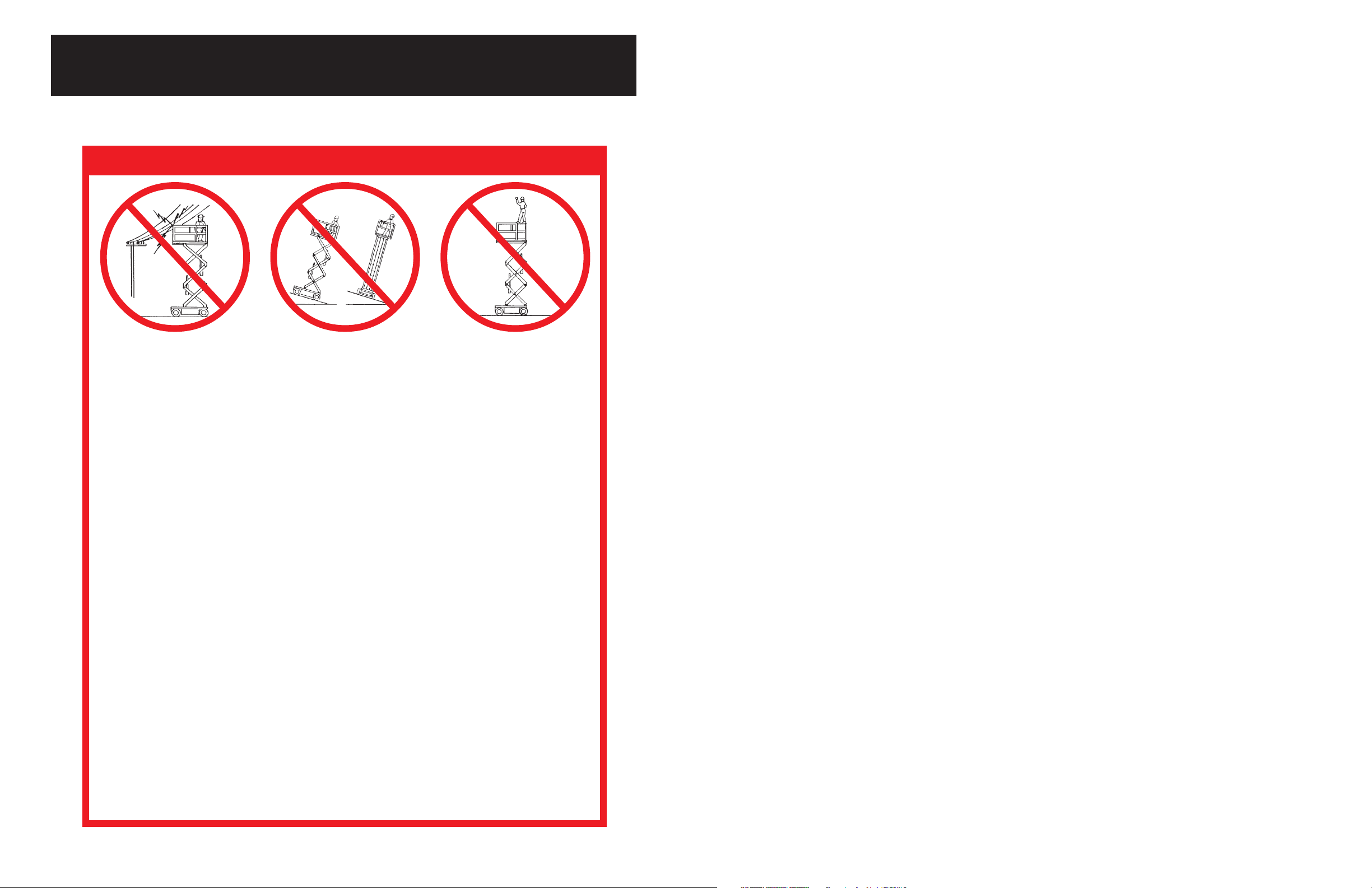
SAFETY RULES
NEVER operate the machine
within 3 m (10 ft) of power
lines. THIS MACHINE IS NOT
INSULATED.
NEVER operate the machine without first surveying the work area for surface hazards such as
holes, drop-offs, bumps and debris.
NEVER operate the machine if all guardrails are not properly in place and secured with all fasten-
ers properly torqued.
SECURE and lock gate after mounting platform.
KEEP all body parts clear of outriggers when extending or retracting (outrigger equipped machines
only).
NEVER use ladders or scaffolding on the platform.
NEVER attach overhanging loads or increase platform size.
MAINTAIN tire pressure at 3.4 bars (50 psi). Check daily.
LOOK up, down and around for overhead obstructions and electrical conductors.
DISTRIBUTE all loads evenly on the platform. See the back cover for maximum platform load.
NEVER use damaged equipment. (Contact UpRight for instructions. See toll-free phone number on
back cover.)
NEVER change operating or safety systems.
INSPECT the machine thoroughly for cracked welds, loose hardware, hydraulic leaks, damaged
control cable, loose wire connections and wheel bolts.
NEVER climb down elevating assembly with the platform elevated.
NEVER perform service on machine while platform is elevated without blocking elevating assem-
bly.
NEVER recharge battery near sparks or open flame; batteries that are being charged emit highly
explosive hydrogen gas.
AFTER USE secure the work platform against unauthorized use by turning key switch off and
removing key.
NEVER replace any component or part with anything other than original UpRight replacement parts
without the manufacturer's consent.
NEVER elevate or drive elevated
on uneven slopes or soft ground
or elevate the platform unless the
platform is level.
NEVER sit, stand or climb
on guardrail or midrail.
2
47
Page 3
UPRIGHT ELECTRICAL SCHEMATIC LX ELECTRIC
PART NO. 067447-003
ENGLISH
CONTROLLER CONTRÔLEUR Steuergerät CONTROLADOR
PLUG NUMBERS NUMÉROS DE FICHE Steckernummern NUMERACÍÓN CONECTOR
DRIVE ENABLE LIGHT TÉMOIN, MODE DE DÉPLACEMENT Fahrbereitschaftsleuchte LUZ DE HABILITACIÓN DE
560 OHM 560 ohms 560 Ohm 560 OHM
TRIGGER IMPULSION DE DÉCLENCHEMENT Triggerschalter GATILLO
ROCKER ARMATURE Wippenschalter BALANCÍN
IGNITION ALLUMAGE Zündung ARRANQUE
EMERGENCY STOP ARRÊT D’URGENCE Notaus-Taster PARADA DE EMERGENCIA
DRIVE DÉPLACEMENT Fahren TRANSMISIÓN
LIFT LEVAGE Heben ELEVACIÓN
HIGH/LOW HAUT/BAS Hochdruck/Niederdruck ALTO/BAJO
EMERGENCY STOP SECTIONNEUR Notaustaster-Schutzschalter FUSIBLE DE PARADA
CIRCUIT BREAKER D’ARRÊT D’URGENCE DE EMERGENCIA
CHASSIS/PLATFORM CHÂSSIS/PLATE-FORME Fahrwerk/Arbeitsbühne CHASIS/PLATAFORMA
DOWN ABAISSÉE abwärts ABAJO
UP LEVÉE aufwärts ARRIBA
LIFT SWITCH SÉLECTEUR DE MODE Hubschalter INTERRUPTOR DE ELEVACIÓN
FONCTIONNEMENT, LEVAGE
LOWER CONTROLS COMMANDES D’ABAISSEMENT untere Bedienorgane CONTROLES INFERIORES
POWER RELAY RELAIS D’ALIMENTATION Stromrelais RELE DE ENERGÍA
DRIVE/LIFT DÉPLACEMENT/LEVAGE Fahren/Heben TRANSMISIÓN/ELEVACIÓN
LEVEL SENSOR CAPTEUR DE NIVEAU Niveausensor SENSOR DE NIVEL
51.7 (750 PSI) 51,7 bars (750 lb/po²) 51,7 bar (750 psi) 51,7 BAR (750 lb/plg2)
TILT ALARM ALARME D’INCLINAISON Neigungswarnung ALARMA DE INCLINACIÓN
DOWN ALARM ALARME D’ABAISSEMENT Senkwarnung ALARMA ABAJO
STEER RIGHT DIRECTION À DROITE Lenkung rechts DIRECCIÓN DERECHA
STEER LEFT DIRECTION À GAUCHE Lenkung links DIRECCIÓN IZQUIERDA
PUMP START DÉMARRAGE, POMPE Pumpenanlauf ARRANQUE DE LA BOMBA
BRAKE FREIN Bremsen FRENO
UP LIMIT LIMITE SUPÉRIEURE Hochfahrbegrenzer LÍMITE SUPERIOR
DOWN ALARM ALARME, ABAISSÉE Senkwarnung ALARMA INFERIOR
BRAKE N.O. FREIN, N.O. Bremse (Schließer) FRENO (ABIERTO)
BRAKE N.C. FREIN, N.F. Bremse (Öffner) FRENO (CERRATO)
RESISTOR PACK BLOC, RÉSISTANCES Widerstandssatz RESISTENCIA
INTERFACE MODULE MODULE D’INTERFACE Schnittstellenmodul MÓDULO DE INTERFASE
PUMP/TRACTION POMPE/TRACTION Pumpe / Traktion BOMBA/TRACCIÓN
LEFT GAUCHE links IZQUIERDA
RIGHT DROITE rechts DERECHA
ARMATURE INDUIT Anker INDUCIDO
FIELD CHAMP Feld CAMPO
POWER UNIT BLOC D’ALIMENTATION Antriebseinheit UNIDAD DE ENERGÍA
PUMP OVERDRIVE SURMODULATION, POMPE Pumpenschnellgang SOBREMARCHA DE LA BOMBA
BATTERY CHARGER CHARGEUR DE BATTERIES Batterieladegerät CARGADOR DE BATERÍA
MAIN POWER ALIMENTATION PRINCIPALE Hauptspannung ENERGÍA PRINCIPAL
CONTROL MODULE MODULE DE COMMANDE Steuergerät MÓDULO DE CONTROL
300 AMP 300 A 300 A 300 AMP
FRANÇAIS GERMAN
LA TRANSMISIÓN
SPANISH
Introduction
This manual covers Electric and BiEnergy of the LX
Series Work Platforms. This manual must be stored on
the machine at all times.
Pre-Operation and Safety
Inspection
Carefully read, understand and follow all safety rules,
labels, and operating instructions, then perform the
following steps each day before use.
Perform a complete visual inspection of the entire unit
prior to operating. Check the following areas for discrepancies:
1. Open panels and check hydraulic components and
hoses for damage or leaks. Check electrical components and wiring for damage or loose connections.
2. Inspect chassis, axles, hubs, and steering linkage for
damage, deformation, buckled paint, loose or missing
hardware, and cracked welds.
3. With platform fully lowered, check the hydraulic oil
level sight gauge on the hydraulic tank . Add ISO #46
hydraulic oil if necessary.
4. Check that fluid level in all batteries is correct (See
Battery Maintenance, Page 9).
5. Check the engine oil level and fuel level (BiEnergy
model).
6. Check that all guardrails are in place. Insure that gate
operates freely and latches securely.
7. Check tires for damage. Check tire pressure; 5.2 bar
(75 psi) if equipped with pneumatic tires.
8. Carefully inspect the entire work platform for damage
such as cracked welds or structural members, loose
or missing parts, oil leaks, damaged cables or hoses,
and loose connections.
9. BiEnergy models - While the engine is cool check the
engine coolant level.
NEVER remove the cap from a hot radiator. Hot
coolant can cause severe burns.
System Function Inspection
STAND CLEAR of the work platform while
performing the following checks.
Before operating the work platform survey the
work area for surface hazards such as holes,
drop-offs, bumps and debris.
Check in ALL directions, including above the
work platform, for obstructions and electrical
conductors.
Protect control console cable from possible
damage while performing checks.
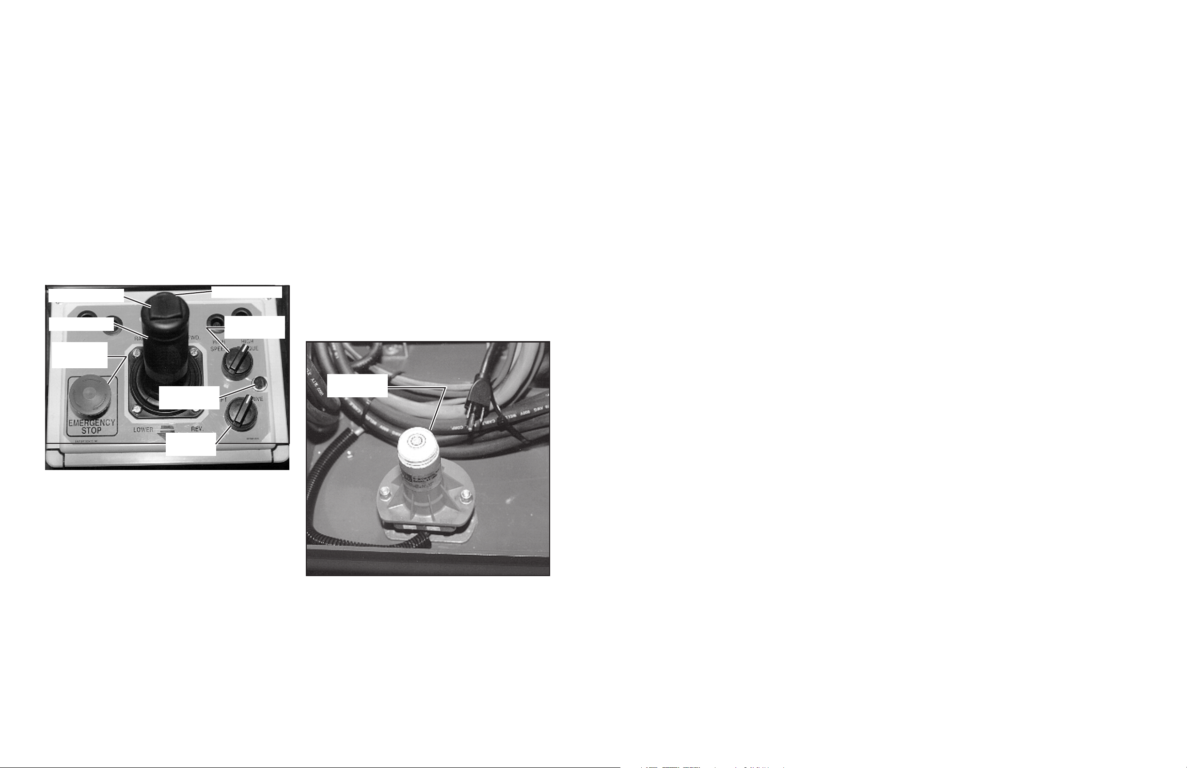
1. Unhook controller from front guardrail. Firmly grasp
controller handle in such a manner that the interlock
lever can be depressed, while performing the
following checks from the ground.
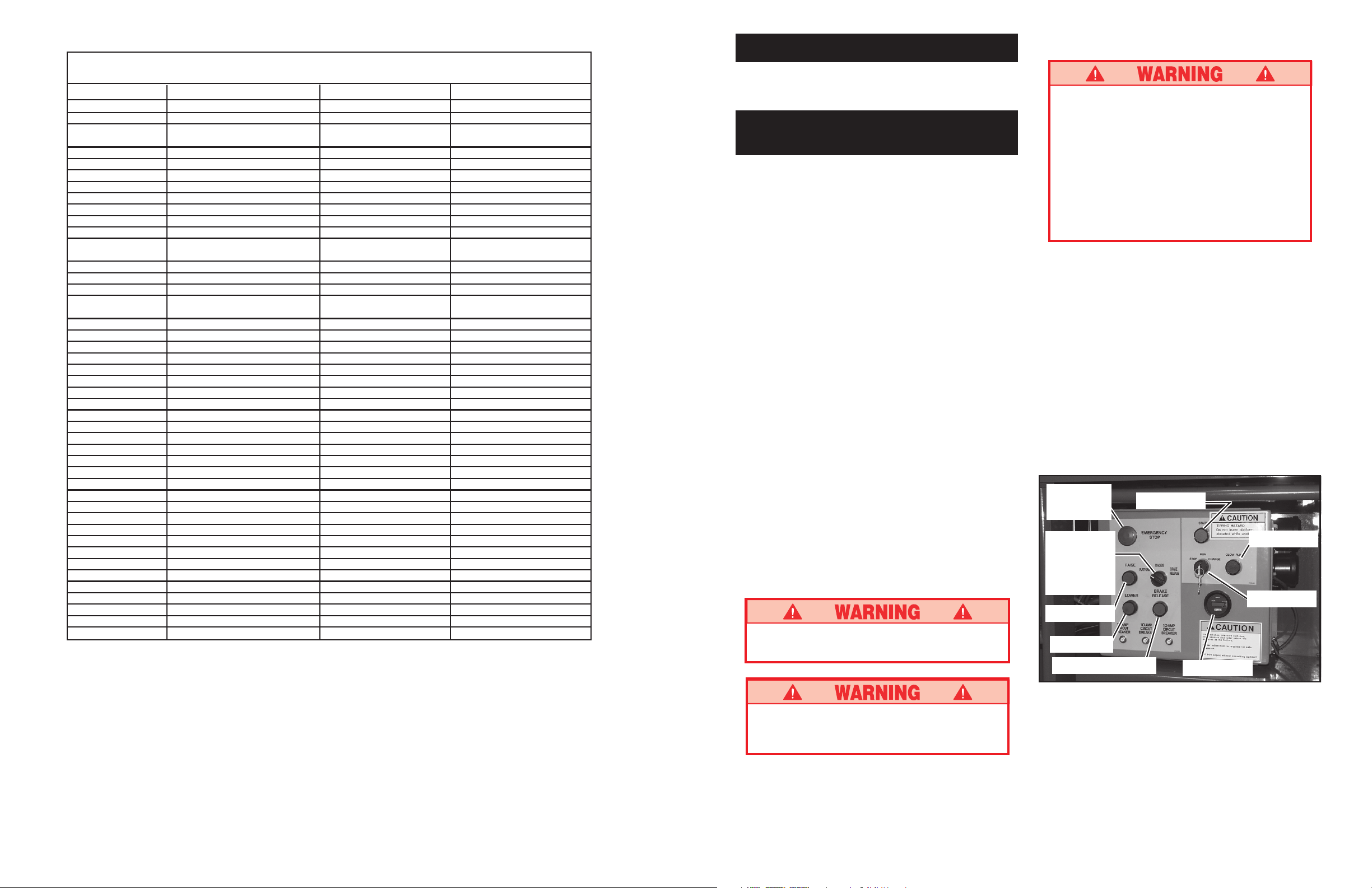
NOTE: BiEnergy machine may be powered by
batteries or by engine. To power the machine by
engine, press the engine start button to crank the
engine. Release button when engine starts. If engine
is cold: press the glow plug button for six seconds
prior to starting.
IMPORTANT: BiEnergy models - If starting engine
from platform be sure engine switch on chassis is set
to "RUN".
Emergency
Stop
Button
Platform/
Chassis/
Brake
Release
Switch
Raise
Lower
Brake Release
Start
Glow Plug
Key Switch
Hour Meter
46
Figure 1: Chassis, Left Side
DO NOT use a machine that is damaged or
malfunctioning. Tag and remove the unit from
service until it is repaired.
3
Page 4
2. Turn controller key switch clockwise to ON.
3. Position drive/lift switch to DRIVE position. Drive
enable indicator will be illuminated.
4. With the speed range switch first in LOW SPEED
and then again in HIGH SPEED depress the interlock
lever and slowly push the control lever to FORWARD
then REVERSE positions to check for speed and
directional control. The farther you push or pull the
control lever the faster the machine will travel.
5. Push steering switch RIGHT then LEFT to check for
steering control.
6. Hook controller on guardrail in original position.
7. Turn the platform/chassis switch to
8. From lower controls, push chassis raise button to
elevate platform while pushing the tilt sensor (Figure 3)
off of level. The platform should only partially elevate
and the tilt alarm should sound. If the platform continues to elevate and/or there is no alarm STOP and
remove the machine from service until it is repaired.
Steering Switch
Control Lever
Emergency
Stop Switch
CHASSIS.
Interlock Lever
Speed Range
Switch
9. Release the tilt sensor and fully elevate platform.
10. Visually inspect the elevating assembly, lift cylinder,
cables and hoses for damage or erratic operation.
Check for missing or loose parts.
11. Lower the platform partially by pushing in on the
chassis lower switch, and check operation of the
audible lowering alarm.
12. Open the chassis emergency lowering valve
(Figure 4) to check for proper operation by pulling
and holding the knob out. Once the platform is fully
lowered, close the valve by releasing the knob.
13. Turn the platform/chassis switch to
14. Mount the platform making sure the gate is latched.
15. Position drive/lift switch to LIFT.
16. Depress the interlock lever and slowly push the
control lever to RAISE to raise the platform, fully
actuate the control lever to check proportional lift
speed. Elevate the platform to 3.7 m (12 feet).
17. Slowly pull control lever to DOWN position to lower
platform. Check that lowering alarm sounds.
18. Turn controller key switch to OFF, push the emergency
stop button and dismount the platform.
19. Close and secure module covers.
PLATFORM.
Drive Enable
Indicator
Lift/Drive
Switch
Figure 2: Controller
Tilt Sensor
Figure 3: Tilt Sensor
4
45
Page 5

UPRIGHT ELECTRICAL SCHEMATIC LX BI-ENERGY
PART NO. 067447-002
ENGLISH
CONTROLLER CONTRÔLEUR Steuergerät CONTROLADOR
PLUG NUMBERS NUMÉROS DE FICHE Steckernummern NUMERACIÓN CONECTOR
DRIVE ENABLE LIGHT TÉMOIN, MODE DE Fahrbereitschaftsleuchte LUZ DE HABILITACIÓN DE LA
DÉPLACEMENT TRANSMISIÓN
560 OHM 560 ohms 560 Ohm 560 OHM
TRIGGER IMPULSION DE DÉCLENCHEMENT Triggerschalter GATILLO
ROCKER ARMATURE Wippenschalter BALANCÍN
IGNITION ALLUMAGE Zündung ARRANQUE
EMERGENCY STOP ARRÊT D’URGENCE Notaus-Taster PARADA DE EMERGENCIA
DRIVE DÉPLACEMENT Fahren TRANSMISIÓN
LIFT LEVAGE Heben ELEVACIÓN
HIGH/LOW HAUT/BAS Hockdruck/Niederdruck ALTO/BAJO
START 12 VOLTS DÉMARRAGE, 12 V Starter 12 V ARRANQUE 12 VOLTIOS
BATTERY 12 VOLTS BATTERIE, 12 V Batterie 12 V BATERÍA 12 VOLTIOS
NEGATIVE NÉGATIF Minuspol NEGATIVO
POSITIVE POSITIF Pluspol POSITIVO
BATTERY CABLE CÂBLE DE BATTERIE Batteriekabel CABLE DE BATERÍA
RECTIFIER REDRESSEUR Gleichrichter RECTIFICADOR
DYNAMO DYNAMO Dynamo DÍNAMO
STARTER RELAY RELAIS DE DÉMARREUR Starterrelais RELÉ DE ARRANQUE
GLOW PLUG RELAY RELAIS DE BOUGIE Glühkerzenrelais RELÉ DE BUJÍA
DE PRÉCHAUFFAGE INCANDESCENTE
KUBOTA GLOW PLUG BOUGIE DE PRÉCHAUFFAGE Kubota-Glühkerze BUJÍA INCANDESCENTE
KUBOTA KUBOTA
12 VOLT CIRCUIT BREAKER SECTIONNEUR, 12 V Schutzschalter 12 V DISYUNTOR DE 12 VOLTIOS
POWER CIRCUIT BREAKER SECTIONNEUR DE PUISSANCE Hauptstrom-Schutzschalter DISYUNTOR DE ENERGÍA
CHARGE CHARGE Ladung CARGA
STARTER DÉMARREUR Starter ARRANCADOR
GLOW PLUG BOUGIE DE PRÉCHAUFFAGE Glühkerze BUJÍA INCANDESCENTE
ENGINE RUN MOTEUR, MARCHE Motorlauf MARCHA DEL MOTOR
EMERGENCY STOP SECTIONNEUR, ARRÊT Notaustaster-Schutzschalter FUSIBLE DE PARADA DE
CIRCUIT BREAKER D’URGENCE EMERGENCIA
CHASSIS/PLATFORM CHÂSSIS/PLATE-FORME Fahrwerk/Arbeitsbühne CHASIS/PLATAFORMA
DOWN ABAISSÉ abwärts ABAJO
UP LEVÉ aufwärts ARRIBA
LIFT SWITCH SÉLECTEUR DE MODE Hubschalter INTERRUPTOR DE
FONCTIONNEMENT, LEVAGE ELEVACIÓN
LOWER CONTROLS COMMANDES D’ABAISSEMENT untere Bedienorgane CONTROLES INFERIORES
POWER RELAY RELAIS D’ALIMENTATION Stromrelais RELÉ DE ENERGIA
DRIVE/LIFT DÉPLACEMENT/LEVAGE Fahren/Heben TRANSMISIÓN/ELEVACIÓN
LEVEL SENSOR CAPTEUR DE NIVEAU Niveausensor SENSOR DE NIVEL
51.7 (750 PSI) 51,7 bars (750 lb/po²) 51,7 bar (750 psi) 51,7 BARS (750 lb/plg2)
TILT ALARM ALARME D’INCLINAISON Neigungswarnung ALARMA DE INCLINACIÓN
DOWN ALARM ALARME D’ABAISSEMENT Senkwarnung ALARMA ABAJO
STEER RIGHT DIRECTION À DROITE Lenkung rechts DIRECCIÓN DERECHA
STEER LEFT DIRECTION À GAUCHE Lenkung links DIRECCIÓN IZQUIERDA
PUMP START DÉMARRAGE, POMPE Pumpenanlauf ARRANQUE DE LA BOMBA
BRAKE FREIN Bremsen FRENO
UP LIMIT LIMITE SUPÉRIEURE Hochfahrbegrenzer LÍMITE ARRIBA
DOWN ALARM ALARME, ABAISSEMENT Senkwarnung ALARMA ABAJO
BRAKE N.O. FREIN, N.O. Bremse (Schließer) FRENO (ABIERTO)
BRAKE N.C. FREIN, N.F. Bremse (Öffner) FRENO (CERRADO)
RESISTOR PACK BLOC DE RÉSISTANCES Widerstandssatz RESISTENCIA
INTERFACE MODULE MODULE D’INTERFACE Schnittstellenmodul MÓDULO DE INTERFASE
PUMP/TRACTION POMPE/TRACTION Pumpe/Traktion BOMBA/TRACCIÓN
LEFT GAUCHE links IZQUIERDA
RIGHT DROITE rechts DERECHA
ARMATURE INDUIT Anker INDUCIDO
FIELD CHAMP Feld CAMPO
POWER UNIT BLOC D’ALIMENTATION Antriebseinheit UNIDAD DE ENERGÍA
PUMP OVERDRIVE SURMODULATION, POMPE Pumpenschnellgang SOBREMARCHA DE LA BOMBA
BATTERY CHARGER CHARGEUR DE BATTERIES Batterieladegerät CARGADOR DE BATERÍA
MAIN POWER ALIMENTATION PRINCIPALE Hauptspannung ENERGÍA PRINCIPAL
CONTROL MODULE MODULE DE COMMANDE Steuergerät MÓDULO DE CONTROL
300 AMP 300 A 300 A 300 AMP
FRANÇAIS GERMAN SPANISH
Operation
Before operating work platform, ensure that the pre-
operation and safety inspection has been completed, any
deficiencies have been corrected and the operator has
been thoroughly trained on this machine.
NOTE: BiEnergy machine may be powered by batteries or by engine. To power the machine by engine,
press engine start button to crank the engine. Release button when engine starts. If engine is cold,
press the glow plug button on chassis control box
for six seconds prior to starting.
IMPORTANT: If starting engine from platform be sure
engine switch on chassis is set to "RUN".
Travel With Platform Lowered
1. Verify chassis emergency stop switch is in the ON
position (pulled out), the drive enable indicator is on,
and that the platform/chassis switch is on PLAT-
FORM.
Note: If the drive enable indicator is off, verify that
the platform is fully lowered.
2. After mounting platform, close and latch gate. Check
that guardrails are in position and properly assembled
with fasteners properly torqued.
3. Check that route is clear of persons, obstructions,
holes and drop-offs and surface is capable of supporting the wheel loads.
4. Check clearances above, below and to the sides of
the platform.
5. Pull controller emergency stop button out to ON
position.
6. Set the speed range switch to LOW SPEED.
7. Grasp the control lever so the interlock lever is
depressed (releasing the interlock lever cuts power to
controller). Slowly push or pull the control lever to
FORWARD or REVERSE to travel in the desired
direction. The farther you push or pull the control
lever from center the faster the machine will travel.
8. While moving, push the speed range switch to HIGH
SPEED for travel on level surfaces or to LOW
SPEED for climbing grades or traveling in confined
areas.
Steering
1. Push the steering switch RIGHT or LEFT to turn the
wheels. Observe the tires while maneuvering to
insure proper direction.
Note: Steering is not self-centering. Wheels must be
returned to the straight ahead position by operating
the steering switch.
Raising and Lowering the Platform
1. Position the drive/lift switch to LIFT.
2. While holding the control lever so the interlock lever
is depressed, push the control lever slowly to UP to
raise the platform. Pushing the control lever farther
increases the lift speed.
3. When the work task is completed, position the drive/
lift switch to LIFT and lower the platform by pulling
back on the control lever until the platform is fully
lowered.
44
5
Page 6
Travel with Work Platform Elevated
Travel with platform elevated ONLY on firm and level
surfaces.
Note: The work platform will travel at reduced speed
when in the elevated position, and then only when
the front axle is parallel with the rear axle.
1. Check that the route is clear of persons, obstructions, holes and drop-offs, surface is level and
capable of supporting the wheel loads.
2. Check clearances above, below and to the sides of
platform.
3. Position the drive/lift switch to the DRIVE position.
4. Push the control lever to FORWARD or REVERSE
for the desired direction of travel.
If the machine quits driving and the tilt alarm
sounds, immediately lower the platform and move
the machine to a level location before re-elevating the
platform.
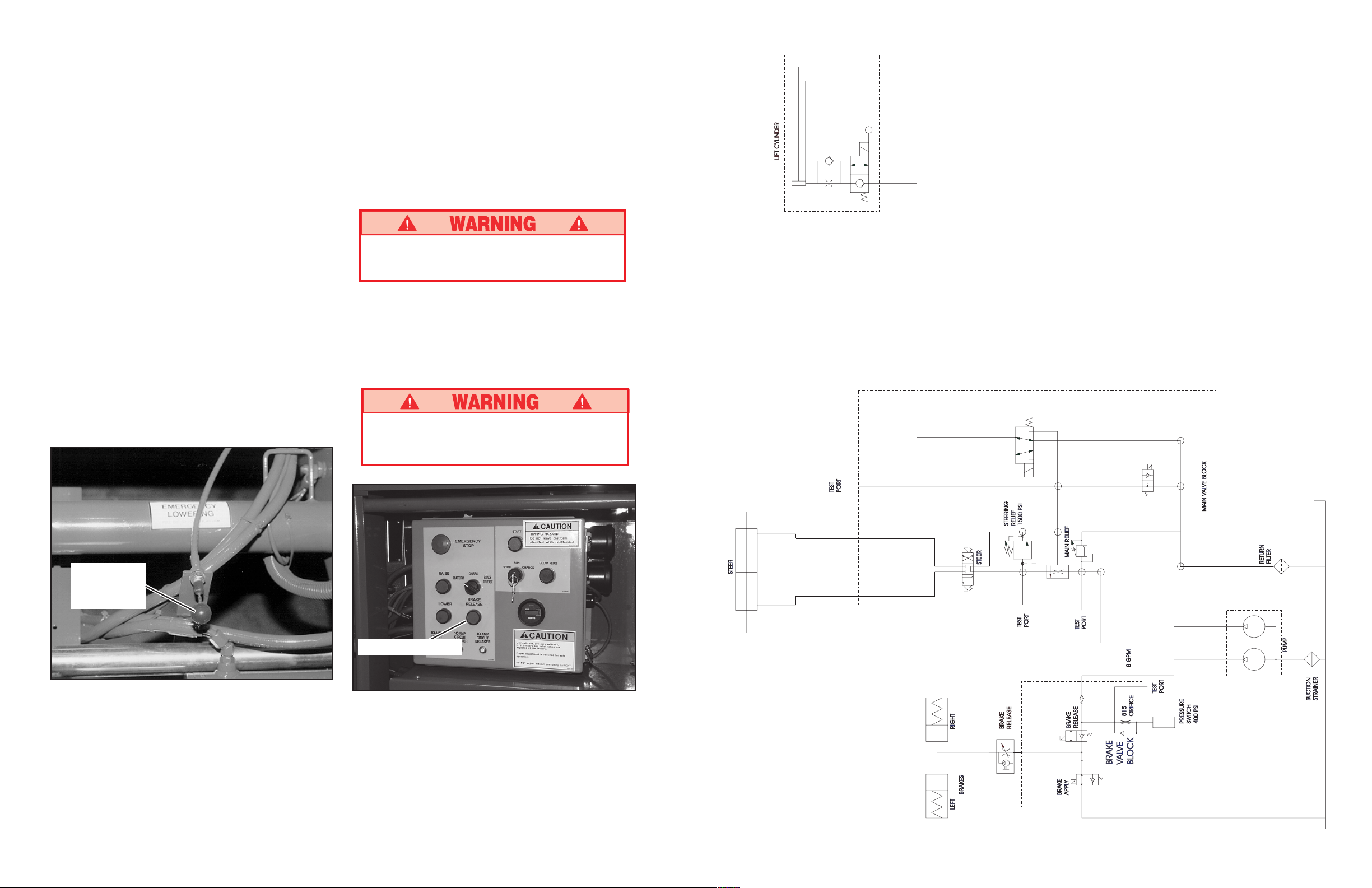
Emergency Lowering
The emergency lowering knob is located at the front
of the machine at the base of the scissor assembly
(Figure 4).
1. Open the emergency lowering valve by pulling on the
knob and holding it.
2. Once the platform is fully lowered, release the knob
to close the valve.
After Use Each Day
1. Ensure that the platform is fully lowered.
2. Park the machine on level ground, preferably under
cover, secure against vandals, children or unauthorized operation.
3. Turn the key switch to OFF and remove the key to
prevent unauthorized operation.
Parking Brake Release (Figure 5)
Perform the following only when the machine will not
operate under its own power and it is necessary to move
the machine or when winching onto a trailer to transport.
Never release brakes if machine is on a slope.
Hook machine to towing vehicle before releasing
brakes.
1. Turn the Platform/Chassis/Brake Release switch to
Brake Release position. Alarm will sound.
2. Momentarily push brake release button.
3. The machine will now roll when pushed or pulled.
4. For normal operation, turn Platform/Chassis/Brake
Release switch to platform.
Never operate work platform with the parking
brakes released. Serious injury or damage could
result.
Emergency
Lowering
Knob
Figure 4: Emergency Lowering Knob
Hydraulic Schematic: LX Electric & BiEnergy - Euro - 067446-000
Brake Release
Figure 5: Parking Brake Release
6
43
Page 7
UPRIGHT HYDRAULIC SCHEMATIC LX ELECTRIC & BI-ENERGY
PART NO. 67446-000
ENGLISH
BRAKES FREINS Bremsen FRENOS
815 ORIFICE ORIFICE 815 Blende 815 ORIFICIO 815
LEFT GAUCHE links IZQUIERDA
RIGHT DROITE rechts DERECHA
SUCTION STRAINER CRÉPINE D’ASPIRATION Ansaugsieb FILTRO DE ASPIRACIÓN
TEST PORT PRISE D’ESSAI Prüfanschluß PUERTO DE PRUEBA
STEER DIRECTION Lenkung DIRIGIR
BRAKE RELEASE DESSERRAGE DES FREINS Bremsbetätigung QUITAR EL FRENO
BRAKE APPLY SERRAGE DES FREINS Bremse anziehen COLOCAR EL FRENO
BRAKE VALVE BLOCK BLOCAGE DE SOUPAPE DE FREIN Bremsventilblock BLOQUE DE VÁLVULA DE FRENO
PRESSURE SWITCH MANOSTAT Druckschalter INTERRUPTOR DE PRESIÓN
27.6 BARS (400 PSI) 27,6 bars (400 lb/po²) 27,6 bar (400 PSI) 27,6 bars (400 lb/plg2)
PUMP POMPE Pumpe BOMBA
MAIN RELIEF DÉCHARGE, PRINCIPALE Überdruck-Hauptventil ALIVIO PRINCIPAL
MAIN VALVE BLOCK BLOCAGE, SOUPAPE PRINCIPALE Hauptventilblock BLOQUE DE LA VÁLVULA
RETURN FILTER FILTRE DE RETOUR Rücklauffilter FILTRO DE RETORNO
STEERING RELIEF DÉCHARGE, DIRECTION, Lenkentlastung ALIVIO DE LA DIRECCIÓN
103 BARS (1500 PSI) 103 bars (1500 lb/po²) 103 bar (1500 PSI) 103 bars (1500 lb/plg2)
LIFT CYLINDER VÉRIN DE LEVAGE Hubzylinder CILINDRO DE ELEVACIÓN
FRANÇAIS GERMAN SPANISH
PRINCIPAL
Fold Down Guardrails
This procedure is only for passing through doorways.
Guardrails must be returned to proper position before
using the machine.
Fold Down Procedure (Figure 6)
Note: When performing the following procedures
retain all fasteners.
1. Place controller on platform.
2. Starting at the front of the platform, remove nuts,
bolts and washers from the top of the front guardrail.
Fold the front guardrail down onto the platform.
3. Close and latch the gate.
4. Remove nuts, bolts and washers from the top of the
rear guardrail. Fold the rear guardrail down onto the
platform being careful to keep gate latched at all
times.
5. Remove nuts, bolts and washers from the top of the
side guardrails and from the slideout deck midrail. Lift
up and fold one side guardrail in so it rests on the
deck. Repeat with other side guardrails.
Erection Procedure
1. Raise side guardrails making sure each is pushed
down to secure the guardrail in the vertical position.
2. Install bolts, washers and nuts between the side
guardrails, tighten securely.
3. Raise rear guardrail assembly, aligning holes and
install bolts, washers and nuts. Tighten securely.
4. Raise front guardrail, aligning holes and install bolts,
washers and nuts. Tighten securely.
5. Hang controller from front guardrail.
6. Before operating work platform check that all fasteners are in place and properly torqued.
Before operating machine, guardrails must be
securely fastened in their proper position.
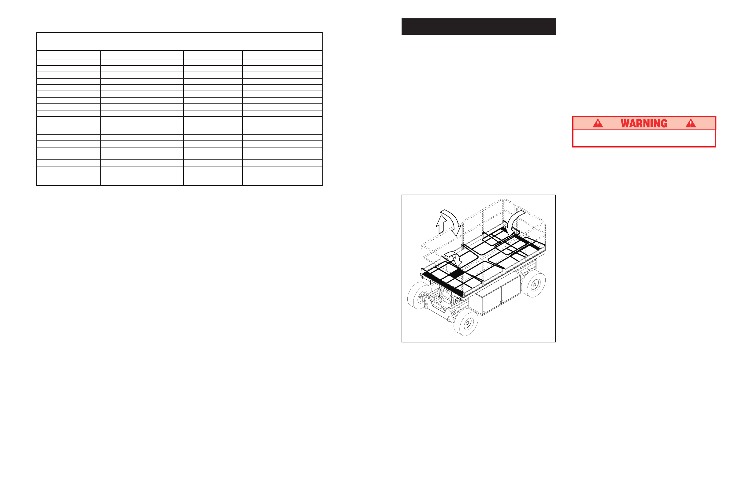
Double Deck Fold Down Procedure
(Figure 7)
NOTE: When performing the following procedures
retain all fasteners.
1. Place controller on platform.
2. Starting at the front; slide out deck, remove hardware
from top front corners of guardrails. Remove hardware
from the slide out deck side guardrail midrails. Also
remove hardware from the top of the sockets that
hold the slide out deck side guardrails to the deck.
Fold the side guardrails down onto the platform.
3. Follow step 2 to fold the front side guardrails on the
rear slide out deck.
4. Unlatch the gate so the left side guardrails can be
folded down in two separate pieces. Also remove the
hardware opposite the gate latch on the right side
guardrail so it can be separated into two pieces.
5. Lift up and fold side guardrails in so they rest on the
deck.
6. Lift up and fold front guardrail in so it rests on the
deck. Repeat for rear guardrail.
42
Figure 6: Fold Down Guardrails
7
Page 8
Double Deck Erection Procedure
1. Raise front guardrail making sure it is pushed down to
secure the guardrail in the vertical position. Repeat
for rear guardrail.
2. Raise guardrails making sure each is pushed down to
secure the guardrail in the vertical position. Align
holes and install hardware. Tighten securely.
3. Raise one of the four slide out deck side guardrail
assemblies. Align holes and install hardware. Tighten
securely. Repeat this procedure for the other three
slide out deck side guardrails.
4. Hang controller from front guardrail.
5. Before operating work platform, check that all fasteners are in place and properly torqued.
step 6
step 2
step 5
step 3
Note: Illustration above is shown with decks
extended for clarity. Perform this procedure with
decks retracted.
Figure 7: Fold Down Guardrails (Double Deck)
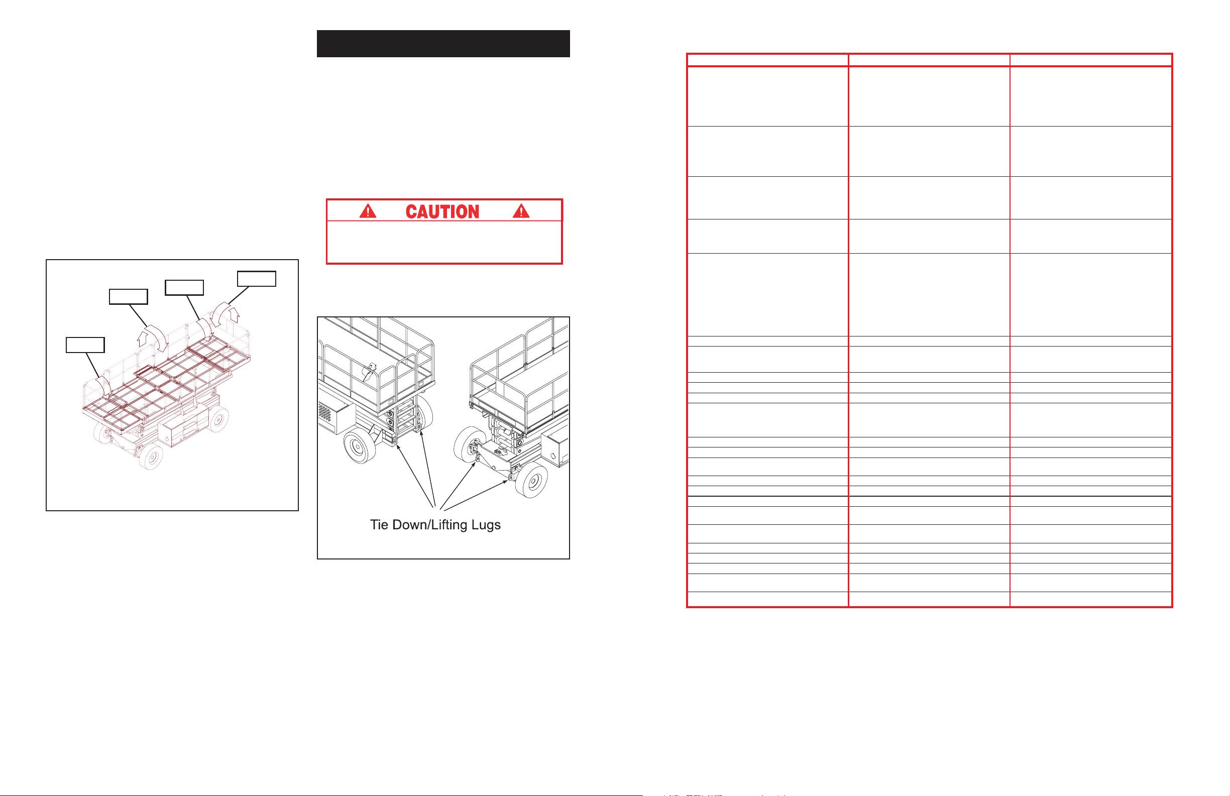
Transporting Work Platform
By Crane
1. Secure straps to chassis tie down/lifting lugs only
(Figure 8).
By Truck
1. Maneuver the work platform into transport position
and chock wheels.
2. Secure the work platform to the transport vehicle with
chains or straps of adequate load capacity attached
to the chassis tie down/lifting lugs (Figure 8).
Overtightening of chains or straps through tie
down lugs may result in damage to work platform.
Figure 8: Transporting Work Platform
Especificaciones*
LX31 LX41ÍTEM
Tamaño de plataforma
(dentro de banda de protección)
Estándar 3,64 m x 1,78 m [143,38 plg x 70 plg] 3,64 m x 1,78 m [143,38 plg x 70 plg]
Con extensión 4,56 m x 1,73 m [179,38 plg x 68 plg] 4,56 m x 1,73 m [179,38 plg x 68 plg]
Modelos de doble cubierta
Con las cubiertas retraídas 3,96 m x 1,73 m [156 plg x 68 plg] 3,96 m x 1,73 m [156 plg x 68 plg]
Con las cubiertas extendidas 5,79 m x 1,73 m [228 plg x 68 plg] 5,79 m x 1,73 m [228 plg x 68 plg]
Capacidad máxima de plataforma
Estándar 907 kg [2 000 lb] 680 kg [1 500 lb]
Con extensión 907 kg [2 000 lb] 680 kg [1 500 lb]
Sobre extensión 227 kg [500 lb] 227 kg [500 lb]
Modelos de doble cubierta 795 kg [1 750 lb] 567 kg [1 250 lb]
en Extensión (solo un extremo) 227 kg [500 lb] 227 kg [500 lb]
Ocupantes, máximo
Estándar 8 personas 6 personas
Sobre extensión 2 personas 2 personas
Modelos de doble cubierta 8 personas 6 personas
en Extensión (solo un extremo) 2 personas 2 personas
Altura
Altura de trabajo 11,28 m [37 pies] 14,33 m [47 pies]
Altura máxima plataforma 9,45 m [31 pies] 12,34 m [40 pies, 6 plg]
Altura mínima plataforma 1,43 m [56,3 plg] 1,66 m [65,3 plg]
Dimensiones
Peso, Eléctrica 2WD: 4 477 kg [9 870 lb]; 2WD: 5 085 kg [11 210 lb]
Peso, Energía doble 2WD : 4 568 kg [10 070 lb] 4WD: 5 176 kg [11 410 lb]
Peso, Eléctrica con extensión2WD: 4 672 kg [10 300 lb] 2WD: 5 280 kg [11 640 lb]
Peso, Energía doble 2WD : 4 763 kg [10 500 lb] 4WD: 5 371 kg [11 890 lb]
Peso, Eléctrica doble cubierta 2WD: 4 866 kg [10 728 lb] 2WD: 5 474 kg [12 068 lb]
Peso, Energía doble 2WD : 4 957 kg [10 928 lb] 4WD: 5 565 kg [12 268 lb]
Ancho total 2,29 m [90 plg] 2,29 m [90 plg]
Altura total 2,53 m [99,75 plg] 2,76 m [108,75 plg]
Largo total, estándar 4,08 m [160,5 plg] 4,08 m [160,5 plg]
Altura de movimiento 9,45 m [31 pies] 12,34 m [40 pies, 6 plg]
Velocidad de avance
Plataforma abajo 0 a 5,0 km/h [0 a 3,1 mph] 0 a 5,0 km/h [0 a 3,1 mph]
Plataforma arriba 0 a 0,48 km/h [0 a 0,3 mph] 0 a 0,48 km/h [0 a 0,3 mph]
Voltaje 48 volts, corriente continua 48 volts, corriente continua
Capacidad estanque hidráulico 107,13 L [28,3 galones EE.UU.] 107,13 L [28,3 galones EE.UU.]
Presión hidráulica máxima 206,8 bars [3 000 lb/plg2] 206,8 bars [3 000 lb/plg2]
Fluido hidráulico
Uso normal (sobre 0 oC [32 oF]) ISO #46 ISO #46
Baja temperatura
(-23 a 0 oC [-10 a 32 oF]) 5W-20 aceite motor 5W-20 aceite motor
Sistema de levante Un cilindro de elevación de una etapa Un cilindro de elevación de una etapa
Velocidad de levante Levante, 45 seg./ Bajada, 65 seg. Levante, 45 seg./ Bajada, 60 seg.
Fuente de potencia Ocho baterías 6V360 AH (doble Ocho baterías 6V360 AH (doble
energía) Una Kubota 12 CV Diesel energía) Una Kubota 12 CV Diesel
Control de tracción Proporcional Proporcional
Sistema de control Palanca manual simple suave Palanca manual simple suave
Tracción horizontal Dos motores de ruedas eléctricos Dos motores de ruedas eléctricos
Neumáticos - estándar 10-16,5 NHS 8 capas 10-16,5 NHS 8 capas
Neumát cos - opcional 3,4 bars [50 lb/plg2] Relleno de poli 3,4 bars [50 lb/plg2) Relleno de poli
Frenos de estacionamiento Dos, por resorte, desenganche Dos, por resorte, desenganche
Radio de giro (interno) 1,22 m [48 plg] 1,22 m [48 plg]
Inclinación máxima 2WD: 30% [16,7o]2WD: 30% [16,7o]
Base de ruedas 2,94 m [115,75 plg] 2,94 m [115,75 plg]
Barandas 1,1 m [43,5 plg] de alto, plegar con 1,1 m [43,5 plg] de alto, plegar con
Banda de protección 152 mm [6 plg] de alto 152 mm [6 plg] de alto
hidráulico, discos múltiples hidráulico, discos múltiples
compuerta de cierre automático compuerta de cierre automático
* Las especificaciones pueden cambiarse sin aviso previo.
Vea en el Manual de mantenimiento la lista completa de repuestos
e información de servicio.
Cumple o excede todos los requisitos apropiados de OSHA y ANSI A92.6-1990.
8
41
Page 9

Mantenimiento de rutina
Use la tabla siguiente como guía para mantenimiento de
rutina. Sólo personal entrenado y que sepa los
procedimientos eléctricos y mecánicos de la
máquina debe inspeccionarla y mantenerla. Consulte
en el Manual de mantenimiento las instrucciones
completas de mantenimiento.
Fotocopie esta página y úsela como hoja de verificación
de mantenimiento de rutina.
Clave de la tabla
Intervalo
Diario = cada turno (cada día) o cada ocho horas
D = cada mes (30 días) o cada cincuenta horas
30
3M = cada 3 meses o cada 125 horas
6
M = cada 6 meses o cada 250 horas
1Y = cada año o cada 500 horas
2Y = cada dos años o cada 1000 horas
S = Si/aceptable
N = No/No aceptable
R = Reparada/Aceptable
Maintenance
Upper Scissor
Center Pivot
Never perform service on the work platform in
the elevating assembly area while platform is
elevated without first blocking the elevating
assembly.
DO NOT stand in elevating assembly area while
deploying or storing brace.
Tabla de mantenimiento de rutina
COMPONENTE INSPECCIÓN O ACTIVIDAD INTERVALO S N R
Aceite motor Verifique nivel y condición Diario
modelos de Verifique goteos Diario
doble energia Cambie filtro y aceite 100 hr
Sistema com- Verifique nivel combustible Diario
bustible motor Verifique goteos Diario
modelos de Cambie filtro combustible 100 hr
doble energia Inspeccione depurador del aire Diario
Batería Verifique nivel electrólito Diario
principal Verifique gravedad específica 30D
Limpie exterior 6M
Inspeccione condición cables Diario
Limpie terminales 6M
Sistema Verifique nivel electrólito Diario
batería Verifique gravedad específica 30D
motor Limpie exterior 6M
modelos de Inspeccione condición cables Diario
doble energia Limpie terminales 6M
Refrigerante Verifique nivel (motor frío) Diario
motor Cambie refrigerante 2Y
Aceite Verifique nivel Diario
hidráulico Cambie filtro 6M
Cambie aceite 2Y
Sistema Verifique goteos Diario
hidráulico Inspeccione conexión de mangueras 30D
Inspeccione desgaste mangueras 30D
Sistema Abra la válvula de bajada de emergencia
hidráulico de e inspeccione condición Diario
emergencia
Contralor Inspeccione operación conmutador Diario
Cable de Inspeccione exterior cable por daños
control
Baranda Verifique par de torsión pernos Diario
y piso Inspeccione soldaduras Diario
plataforma Inspeccione condición de piso Diario
Neumáticos Inspeccione condición Diario
Verifique presión 5,2 bars (75 lb/plg2) Diario
Verifique tensión tuercas 205 Nm (150 lbs.-pies) 30D
Bomba Limpiado exterior 30D
hidráulica Examine fugas por junturas 30D
Verifique goteos conectores mangueras Diario
Verifique par de torsión de pernos 30D
Motores Inspeccione operación y goteos
hidráulicos
Sistema de Verifique par de torsión de pernos y conectores 6M
dirección Lubrique puntos pivotes 30D
Verifique goteos y par de torsión de cilindro
de dirección
Diario
Diario
30D
COMPONENTE INSPECCIÓN O ACTIVIDAD INTERVALO S N R
Mecanismo Verifique integridad estructura Diario
de tijera Inspeccione desgaste pivotes 30D
Verifique par de torsión de pernos de
pasadores pivotes
Inspeccione dobladuras de brazos de tijeras 6M
Engrase pasadores de tijeras 30D
Chasis Inspeccione mangueras por
estrangulaciones o roces
Verifique par de torsión de componentes
de montaje
Verifique integridad de soldaduras Diario
Cilindro de Verifique condición vástago 30D
levante Verifique par de torsión de pernos de
pasadores
Revise sellos por fugas 30D
Inspeccione desgaste de puntos pivote 30D
Verifique par de torsión de conectores 30D
Cilindro Verifique condición vástago 30D
del eje Verifique par de torsión de pernos
de pasadores
Revise sellos por fugas 30D
Inspeccione desgaste de puntos pivote 30D
Verifique par de torsión de conectores 30D
Unidad Revise y repare daños de colisión Diario
completa Verifique par de torsión de pernos 3M
Inspeccione por corrosión; limpie y pinte 6M
Lubricar 30D
Calcomanías Reemplace las dañadas, ilegibles o sueltas Diario
30D
Diario
6M
30D
30D
Informe de mantenimiento
Fecha:
Dueño:
Modelo No.: No. serie:
Mecánico:
Intervalo:
Blocking Elevating Assembly
(Figure 9)
Installation
1. Park the work platform on firm level ground.
2. Verify platform emergency stop switch is ON.
3. Turn platform/chassis switch to CHASSIS.
4. Elevate platform far enough to allow brace to be
lowered.
5. From the left side of the machine, disengage the
locking pin securing the brace. Rotate the scissor
brace counterclockwise until it is vertical and between
the two scissor center pivots.
6. Slowly lower platform until brace is supporting the
platform.
Removal
1. Using chassis controls, raise platform until the
scissors brace clears the two scissor center pivots.
2. Rotate scissors brace clockwise until the locking pin
engages.
3. Lower platform completely.
Brace
Locking Pin
Lower Scissor
Center Pivot
Figure 9: Blocking Elevating Assembly
Battery Maintenance
Hazard of explosive gas mixture. Keep sparks,
flame and smoking materials away from batteries.
Always wear safety glasses when working with
batteries.
Battery fluid is highly corrosive. Rinse away any
spilled fluid thoroughly with clean water.
Always replace batteries with UpRight batteries
or manufacturer approved replacements weighing
54.4 kg (120 lbs.) each.
Check battery fluid level daily, especially if work platform
is being used in a warm, dry climate.
If electrolyte level is lower than 10 mm (3/8 in.) above
plates add distilled water only. DO NOT use tap water
with high mineral content it will shorten battery life.
Keep terminals and tops of batteries clean.
Refer to the Service Manual to extend battery life and for
complete service instructions.
40
9
Page 10

Routine Service
Use the following table as a guide for routine maintenance. Inspection and maintenance shall be
performed by personnel who are trained and familiar
with mechanical and electrical procedures. Refer to
the Service Manual for complete service instructions.
Please copy this page and use the Routine Service
Table as a checklist when inspecting a machine for
service.
Routine Service Table Key
Interval
Daily=each shift (every day) or every eight hours
30D=every month (30 days) or every 50 hours
3M=every 3 months or 125 hours
6M=every 6 months or 250 hours
1Y=every year or 500 hours
Y=every 2 years or 1000 hours
2
Y=Yes/Acceptable
N=No/Not Acceptable
R=Repaired/Acceptable
Mantenimiento
Jamás mantenga el mecanismo de tijera de la
plataforma de trabajo con la plataforma
levantada sin haber bloqueado antes ese
mecanismo.
NO se pare en el área del mecanismo de tijera al
instalar o guardar el puntal.
Pivote central
de tijera
superior
Routine Service Table
COMPONENT INSPECTION OR SERVICES INTERVAL Y N R
Engine Oil Check level and condition Daily
BiEnergy Check for leaks Daily
Models Change oil & filter 100HOURS
Engine Fuel Check fuel level Daily
System Check for leaks Daily
BiEnergy Replace fuel filter 100 HOURS
Models Check air cleaner Daily
Main Check electrolyte level Daily
Battery Check specific gravity 30D
Pack Clean exterior 6M
Engine Check electrolyte level Daily
Battery Check specific gravity 30D
System Clean exterior 6M
BiEnergy Check battery cable condition Daily
Models Clean terminals 6M
Engine Check coolant level (with engine cold) Daily
Coolant Replace coolant 2Y
Hydraulic Check oil level Daily
Oil Change filter 6M
Hydraulic Check for leaks Daily
System Check hose connections 30D
Emergency Open the emergency lowering valve and
Hydraulic check for serviceability Daily
System
Controller Check switch operation Daily
Control Check the exterior of the cable
Cable for pinching, binding or wear
Platform Check fasteners for proper torque Daily
Deck and Check welds for cracks Daily
Rails Check condition of deck Daily
Tires Check for damage Daily
Hydraulic Wipe clean 30D
Pump Check for leaks at mating surfaces 30 D
Drive Motors Check for operation and leaks Daily
Steering Check hardware & fittings
System for proper torque
Check battery cable condition Daily
Clean terminals 6M
Drain and replace oil 2 Y
Check hoses for exterior wear 30D
Daily
Check air pressure 5.2 bars (75 psi) Daily
Check lug nuts (torque to 205 Nm [150 ft. lbs.]) 30D
Check for hose fitting leaks Daily
Check mounting bolts for proper torque 30D
6M
Oil all pivot points 30D
Check steering cylinder for leaks &
mounting bolts for proper torque
30D
COMPONENT INSPECTION OR SERVICES INTERVAL Y N R
Elevating Inspect for structural cracks Daily
Assembly Check pivot points for wear 30D
Check pivot pin mounting bolts
for proper torque
Check scissor arms for bending 6M
Grease scissor pins 30D
Chassis Check hoses for pinch or rubbing points Daily
Check component mounting for proper torque 6M
Check welds for cracks Daily
Lift Check the cylinder rod for wear 30D
Cylinder Check pivot pin mounting bolts for proper torque 30D
Check seals for leaks 30D
Inspect pivot points for wear 30D
Check fittings for proper torque 30D
Axle Check the cylinder rod for wear 30D
Cylinder Check mounting pin pivot bolts for proper torque 30D
Check seals for leaks 30D
Inspect pivot points for wear 30D
Check fittings for proper torque 30D
Entire Check for and repair collision damage Daily
Unit Check fasteners for proper torque 3M
Check for corrosion-remove and repaint 6M
Lubricate 30D
Labels Check for peeling, missing, or unreadable
labels & replace
30D
Daily
Service Report
Date: ________________
Owner: _________________
Model No: ____________ Serial No: _____________
Serviced By: ____________
Service Interval: _________
Bloqueando el mecanismo de tijera
(figura 9)
Instalación
1. Estacione la plataforma de trabajo en piso horizontal
firme.
2. Verifique que el interruptor de paradas de
emergencia esté conectado “ON”.
3. Gire el conmutador plataforma/chasis a chasis
“CHASSIS”.
4. Eleve la plataforma lo más lejos posible para permitir
que la abrazadera baje.
5. Desde el lado izquierdo de la máquina, saque el
pasador de enganche que asegura el brazo. Gire el
brazo de las tijeras contra las manecillas del reloj
hasta que esté vertical y entre los dos pivotes de las
tijeras.
6. Baje la plataforma lentamente hasta que la
abrazadera sostenga la plataforma.
Remoción
1. Desde los controles del chasis levante la plataforma
hasta que el puntal de las tijeras salga de los dos
pivotes centrales.
2. Gire el puntal en el sentido de los punteros del reloj
hasta que el pasador de enganche encaje.
3. Baje completamente la plataforma.
Puntal
Pasador de
enganche
Pivote central de
tijera inferior
Figura 9: Bloqueo del mecanismo de tijera
Mantenimiento de la batería
Peligro de mezcla de gases explosiva. Mantenga
las baterías lejos de chispas, llamas o de
cigarrillos.
Cuando trabaje con baterías, use siempre
anteojos de seguridad.
Los electrólitos son muy corrosivos. Lave bien
los derrames con agua limpia.
Use siempre baterías UpRight de repuesto o
aquellas aprobadas por el fabricante como tales
y que pesen 54,4 kg (120 lb) c/u.
Inspeccione el nivel de electrólito diariamente,
especialmente si la plataforma de trabajo se usa en un
clima seco y cálido.
Si el electrólito está a menos de 10 mm (3/8 plg) del
tope de las placas agregue sólo agua destilada. NO use
agua potable con alto contenido de minerales para no
acortar la vida de la batería.
Mantenga los terminales y las baterías limpias.
Consulte en la Manual de mantenimiento como
incrementar la vida de la batería y las instrucciones
completas de mantenimiento.
10
39
Page 11

Procedimiento de elevación para
modelos de doble cubierta
1. Levante la baranda delantera y empújela hacia abajo
para asegurar la baranda en posición vertical. Repita
la operación para la baranda trasera.
2. Levante las barandas laterales y empújelas hacia
abajo para asegurarlas en posición vertical, alínee
los orificios e instale los pernos, arandelas y
tuercas. Asegúrelos firmemente.
3. Levante uno de los cuatro ensamblados de las
barandas laterales de la cubierta de deslizamiento.
Alinee los orificios e instale los elementos de
montaje. Asegúrelos firmemente. Repita este
proceso para las otras tres barandas laterales de la
cubierta de deslizamiento.
4. Cuelgue el contralor en la baranda delantera.
5. Antes de operar la plataforma de trabajo verifique que
los pernos estén en su lugar y apretados al par de
torsión correcto.
paso 6
paso 2
paso 5
paso 3
Nota: La illustración de arriba muestra las cubiertas
extendidas con el propósito de clarificar. Realice
este procedimiento con las cubiertas retrídas.
Figura 7: Plegar la baranda (doble cubierta)
Transportar la plataforma
de trabajo
Por grúa
1. Asegure las correas sólo a los anillos de amarre o
levante (fig. 8).
Por camión
1. Mueva la plataforma de trabajo a la posición para
transporte y acuñe las ruedas.
2. Asegure la plataforma de trabajo al vehículo de
transporte con cadenas o correas, de resistencia
adecuada para la carga, desde los anillos de
amarre (fig. 8).
Sobreestirar cadenas o correas desde los
anillos puede dañar la plataforma de trabajo.
Anillos de amarre para asegurar o levantar
Figura 8: Transportando la plataforma de trabajo
ITEM
Platform Size (Inside Toeboards)
Standard
w/ Extension
Double Deck Models
w/ Decks Retracted
w/ Decks Extended
Max. Platform Capacity
Standard
w/ Extension
on Extension
Double Deck Models
on Extension (one end only)
Max. No. of occupants
Standard
on Extension
Double Deck Models
on Extension (one end only)
Height
Working Height
Max. Platform Height
Min. Platform Height
Dimensions
Weight, Electric
Overall Width
Overall Height
Overall Length, Standard
Driveable Height
Surface Speed
Platform Lowered
Platform Raised
System Voltage
Hydraulic Tank Capacity
Maximum Hydraulic System Pressure
Hydraulic Fluid
Normal Use (> 0 °C [32 °F])
Low Temp. Use
(-23 to 0 °C [-10 to 32 °F])
Lift System
Lift Speed
Power Source
Drive Control
Control System
Horizontal Drive
Tires Standard
Parking Brakes
Turning Radius (inside)
Maximum Gradeability
Wheel Base
Guardrails
Toeboard
BiEnergy
Electric w/ Extension
BiEnergy
Electric Double Deck
BiEnergy
Optional
LX31
3.64 m x 1.78 m [143.38 in. x 70 in.]
4.56 m x 1.73 m [179.38 in. x 68 in.]
3.96 m x 1.73 m [156 in. x 68 in.]
5.79 m x 1.73 m [228 in. x 68 in.]
907 kg [2000 lbs.]
907 kg [2000 lbs.]
227 kg [500 lbs.]
795 kg [1750 lbs.]
227 kg [500 lbs.]
8 people
2 people
8 people
2 people
11.28 m [37 ft.]
9.45 m [31 ft.]
1.43 m [56.3 in.]
2WD: 4,477 kg [9,870 lbs.]
2WD: 4,568 kg [10,070 lbs.]
2WD: 4,672 kg [10,300 lbs.]
2WD: 4,763 kg [10,500 lbs.]
2WD: 4,866 kg [10,728 lbs.]
2WD: 4,957 kg [10,928 lbs.]
2.29 m [90 in.]
2.53 m [99.75 in.]
4.08 m [160.5 in.]
9.45 m [31 ft.]
0 to 5.0 km/h [0 to 3.1 mph]
0 to .48 km/h [0 to 0.3 mph]
48 Volt DC
107.13 l [28.3 Gallons]
206.8 bar [3000 psi]
ISO #46
5W-20 Motor Oil
One Single Stage Lift Cylinder
Raise, 40 sec./Lower, 60 sec.
Eight 6V 350 AH Batteries
(BiEnergy) One Kubota 12 HP Diesel
Proportional
Smooth one hand Joystick
Two Electric Wheel Motors
10-16.5 NHS 8 Ply, 3.4 bar [50psi]
Poly Filled
Two, Spring Applied, Hydraulic Release,
Multiple Disc
1.22 m [48 in.]
2WD: 30% [16.7º]
2.94 m [115.75 in.]
1.1 m [43.5 in.] high, Fold Down with Self
Closing Gate
152 mm [6 in.] High
LX41
3.64 m x 1.78 m [143.38 in. x 70 in.]
4.56 m x 1.73 m [179.38 in. x 68 in.]
3.96 m x 1.73 m [156 in. x 68 in.]
5.79 m x 1.73 m [228 in. x 68 in.]
680 kg [1,500 lbs.]
680 kg [1,500 lbs.]
227 kg [500 lbs.]
567 kg [1,250 lbs]
227 kg [500 lbs.]
6 people
2 people
6 people
2 people
14.33 m [47 ft.]
12.34 m [40 ft. 6 in. ]
1.66 m [65.3 in. ]
2WD: 5,085 kg [11,210 lbs.]
4WD: 5,176 kg [11,410 lbs.]
2WD: 5,280 kg [11,640 lbs.]
4WD: 5,371 kg [11,890 lbs.]
2WD: 5,474 kg [12,068 lbs.]
4WD: 5,565 kg [12,268 lbs.]
2.29 m [90 in.]
2.76 m [108.75 in.]
4.08 m [160.5 in.]
12.34 m [0 ft. 6 in.]
0 to 5.0 km/h [0 to 3.1 mph]
0 to .48 km/h [0 to 0.3 mph]
48 Volt DC
107.13 l [28.3 Gallons]
206.8 bar [3000 psi]
ISO #46
5W-20 Motor Oil
One Single Stage Lift Cylinder
Raise, 40 sec./Lower, 60 sec.
Eight 6V 350 AH Batteries
(BiEnergy) One Kubota 12 HP Diesel
Proportional
Smooth one hand Joystick
Two Electric Wheel Motors
10-16.5 NHS 8 Ply, 3.4 bar [50psi]
Poly Filled
Two, Spring Applied, Hydraulic Release,
Multiple Disc
1.22 m [48 in.]
2WD: 30% [16.7º]
2.94 m [115.75 in.]
1.1 m [43.5 in.] high, Fold Down with Self
Closing Gate
152 mm [6 in.] High
38
* Specifications subject to change without notice.
Refer to Service Manual for complete parts and service information.
Meets or exceeds all applicable requirements of OSHA and ANSI A92.6-1990
11
Page 12

Version française
RÈGLES DE SÉCURITÉ
NE JAMAIS utiliser la machine
à moins de 3 mètres (10 pi) de
lignes d’énergie électrique.
CETTE MACHINE N’EST PAS
ISOLÉE.
NE JAMAIS utiliser la machine sans avoir d’abord vérifié si la surface de la zone de travail ne
présente pas de dangers, tels que des trous, des dénivellations, des bosses et des débris.
NE JAMAIS utiliser la machine sans que tous les garde-corps soient bien montés en place et
fixés solidement au moyen de toutes les pièces de fixation serrées au bon couple.
REFERMER et verrouiller le portillon après être monté sur la plate-forme.
NE PAS s’approcher des stabilisateurs au moment d’élever ou d’abaisser la plate-forme. (Ma-
chines équipées de stabilisateurs seulement).
NE JAMAIS dresser d’échelle ni d’échafaudage sur la plate-forme.
NE JAMAIS agrandir la surface de la plate-forme, ni y fixer une charge qui la déborde.
MAINTENIR la pression des pneus à 3,4 bars (50 lb/po2) . Vérifier chaque jour.
REGARDER en haut, en bas et tout autour de la machine afin de s’assurer qu’il n’y a aucun
conducteur électrique ou autre obstacle aux alentours.
RÉPARTIR également toutes les charges sur la plate-forme. Pour connaître la capacité
maximale de cette dernière, voir la fiche technique à la page couverture arrière.
NE JAMAIS utiliser une machine endommagée. (Si la machine est endommagée, communiquer
avec UpRight en composant le numéro sans frais inscrit à la page couverture arrière.)
NE JAMAIS modifier les éléments assurant le fonctionnement de la machine, ni les dispositifs de
sécurité.
VÉRIFIER la machine de fond en comble en s’assurant que toutes les soudures et tous les
câbles électriques ou de commande sont en bon état, que toutes les pièces de fixation sont bien
serrées, y compris les boulons de fixation des roues, que le circuit hydraulique ne présente
aucune fuite et que tous les fils électriques sont bien branchés.
NE JAMAIS descendre par le dispositif d’élévation lorsque la plate-forme est élevée.
NE JAMAIS effectuer des travaux d’entretien dans la zone du dispositif d’élévation d’une plate-
forme élevée sans avoir d’abord bloqué ce dernier au moyen d’un étai.
NE JAMAIS recharger la batterie d’accumulateurs près d’une flamme ou d’une source d’étincelles :
au moment du rechargement, les batteries dégagent de l’hydrogène gazeux hautement explosif.
APRÈS AVOIR UTILISÉ la plate-forme élévatrice, tourner la clé de l’interrupteur à la position
d’arrêt « OFF », puis la retirer afin de prévenir l’utilisation de la plate-forme par toute personne
non autorisée.
NE JAMAIS remplacer quelque élément ou quelque pièce que ce soit par autre chose qu’une
pièce d’origine UpRight, sans le consentement du fabricant.
NE JAMAIS élever la plate-forme
sur des pentes de surface inégale
ou sur un sol mou, ni déplacer la
machine en pareilles conditions,
ni élever la plate-forme si celle-ci
n’est pas de niveau.
12
NE JAMAIS s’asseoir, monter
ou se mettre debout sur les
rampes du garde-corps de la
plate-forme.
Abatiendo barandas
Use este procedimiento sólo para pasar por puertas.
Vuelva las barandas a su posición correcta antes de
usar la máquina.
Procedimiento para abatir (figura 6)
Nota: Cuando ejecute este procedimiento guarde los
pernos, tuercas y arandelas.
1. Coloque el contralor en la plataforma.
2. Empezando por el frente, saque los pernos, tuercas
y arandelas de encima de la baranda delantera.
Abata la baranda delantera sobre la plataforma.
3. Cierre la puerta con pestillo.
4. Saque los pernos, tuercas y arandelas de encima de
la baranda trasera. Abata la baranda sobre la
plataforma cuidando mantener la puerta con pestillo
todo el tiempo.
5. Saque los pernos, tuercas y arandelas de encima de
las barandas laterales y del eje medio de la
plataforma deslizante. Levante y voltee la baranda
de un lado dejándola sobre la plataforma. Repítalo
con la baranda opuesta.
Figura 6: Abatiendo barandas
Procedimiento de elevación
1. Levante las barandas laterales y empújelas hacia
abajo para asegurarlas en la posición vertical.
2. Instale pernos, arandelas y tuercas entre las
barandas laterales y apriételos bien.
3. Levante el ensamble de la baranda trasera, alinee
hoyos e instale pernos, arandelas y tuercas.
4. Levante la baranda delantera, alinee agujeros e
instale pernos, arandelas y tuercas. Apríetelos bien.
5. Cuelgue el contralor en la baranda delantera.
6. Antes de operar la plataforma de trabajo verifique
que los pernos estén en su lugar y apretados al par
de torsión correcto.
Antes de operar la máquina, las barandas deben
estar aseguradas en su posición correcta.
Procedimiento de plegado para los
modelos de doble cubierta (figura 7)
Nota: Cuando se realiza el siguiente procedimiento
guardar todos los sujetadores.
1. Coloque el controlador sobre la plataforma
2. Comenzando desde el frente de la máquina, la
cubierta de deslizamiento, quite los elementos de
montaje de los extremos superiores delanteros de
las barandas. Quite los elementos de montaje de la
baranda lateral de la cubierta de deslizamiento.
También quite los elementos de montaje de la parte
superior de los soportes que unen la baranda lateral
de la cubierta de deslizamiento con la cubierta.
Doble las barandas laterales sobre la plataforma.
3. Siga el paso 2 para plegar la baranda lateral sobre la
cubierta de deslizamiento trasera.
4. Destrabe la compuerta de modo que se pueda plegar
la baranda lateral izquierda en dos piezas separadas.
También quite los elementos de montaje que se
encuentran frente al pestillo de la compuerta en la
baranda lateral derecha, para poder separarla en dos
piezas.
5. Levante y pliegue la baranda lateral hacia adentro de
modo que quede sobre la cubierta.
6. Levante y pliegue la baranda delantera hacia adentro
de modo que quedesobre la cubierta. Repita la
peración con la baranda trasera.
37
Page 13

Traslado con la plataforma elevada
Traslade la plataforma elevada SÓLO en superficies
firmes y horizontales.
Nota: La máquina se moverá a velocidad reducida
con la plataforma elevada, y sólo cuando ambos ejes
están paralelos.
1. Cersiórese de que no haya personas, obstrucciones,
hoyos y desniveles en el camino y que la superficie
sea capaz de resistir la carga de las ruedas.
2. Verifique el espacio libre sobre, debajo y en los lados
de la plataforma.
3. Coloque el conmutador manejo/levante en la
posición de manejo “DRIVE”.
4. Empuje la palanca de control a avance
“FORWARD” o retroceso “REVERSE” según la
dirección de movimiento deseada.
Si la máquina se detiene y la alarma de inclinación
suena, baje la plataforma de inmediato y mueva la
máquina a un lugar horizontal antes de levantar la
plataforma de nuevo.
Bajada de emergencia
La válvula de bajada de emergencia se encuentra en
el frente de la máquina en la base del mecanismo de
tijera (fig. 4).
1. Abra la perilla de bajada de emergencia tirando y
sosteniendo la manilla.
2. Cuando la plataforma esté abajo, suelte la manilla
para cerrar la válvula.
Manilla de
bajada de
emergencia
Figura 4: Manilla de bajada de emergencia
Después de cada uso diario
1. Cerciórese que la plataforma esté totalmente abajo.
2. Estacione la máquina en piso horizontal, de
preferencia bajo techo, asegurada contra vándalos,
niños o usos no autorizados.
3. Apague el motor y saque la llave “OFF” para
prevenir usos no autorizados.
Desenganche del freno de
estacionamiento (figura 5)
Ejecute lo siguiente sólo cuando la máquina no opere por
si misma y es necesario moverla, o al tirarla sobre un
remolque para transporte.
Nunca suelte los frenos cuando la unidad està
en una pendiente. Enganche la unidad a un
vehìculo de remolque antes de soltar los frenos.
1. Coloque el interruptor de desenganche del freno/
plataforma/ chasis, en la posición de desenganche
del freno. La alarma sonará.
2. Apriete por un momento el botón de desenganche del
freno.
3. Las ruedas de la máquina girarán al empujarla o
tirarla.
4. Para la operación normal, coloque el interruptor
plataforma/chasis, desenganche del freno en
plataforma.
Jamás opere la plataforma de trabajo sin los
frenos de estacionamiento enganchados. Ello
puede resultar en lesiones o daños serios.
Desenganche del
freno
Introduction
Ce manuel se rapporte à l'utilisation des modèles
électrique et bi-énergie de plate-formes élévatrices de
travail appartenant à la série LX. On veillera à le garder
sur la machine en tout temps.
Vérification préliminaire
de sécurité
Lire d’abord attentivement toutes les règles de
sécurité, les étiquettes et le mode d’emploi, en
s’assurant de les comprendre et de s’y conformer.
Chaque jour avant d’utiliser la machine, exécuter les
tâches suivantes.
Effectuer une inspection visuelle complète de la machine
avant de l’utiliser.
1. Ouvrir les panneaux, et vérifier que les composants des
circuits hydrauliques/les tuyaux ne présentent pas de
fuites ni de dommages. Vérifier qu’aucun composant
ou filage électrique ne présente de dommages ni de
connexions ayant du jeu.
2. Vérifier à fond le châssis, les essieux, les moyeux et la
timonerie de direction pour s’assurer qu’ils ne
présentent pas de dommages, de déformations, de
peinture gondolée, de pièces de fixation ayant du jeu ou
qui manquent, ni de soudures fissurées.
3. La plate-forme étant complètement abaissée, vérifier
la jauge de niveau du réservoir d’huile hydraulique.
Faire l’appoint d’huile hydraulique ISO no 46, au
besoin.
4. S’assurer que le niveau d’électrolyte de toutes les
batteries est correct. (Voir « Entretien de la batterie »,
à la page 19.)
5. Vérifier le niveau d'huile du moteur et le niveau de
carburant (modèles bi-énergie).
6. S’assurer que tous les garde-corps sont en place.
Veiller à ce que le portillon fonctionne librement et
s’enclenche fermement.
7. Vérifier si les pneus ne sont pas endommagés.
Vérifier la pression des pneus; elle doit être de
5,2 bars (75 lb/po2), si la machine est équipée de
pneumatiques.
8. Vérifier la plate-forme élévatrice de fond en comble
en s’assurant que les soudures et toutes les pièces –
comme les éléments porteurs, les câbles électriques,
les tuyaux flexibles et les pneus – sont en bon état,
que toutes les pièces sont fixées solidement en place
et qu’aucune d’elles ne manque, qu’il n’y a aucune
fuite d’huile et que tous les fils électriques sont bien
branchés.
9. Modèles bi-énergie - Une fois le moteur refroidi,
vérifier le niveau de liquide de refroidissement.
NE PAS utiliser la machine si elle est endommagée ou en mauvais état de fonctionnement.
Apposer une étiquette volante sur la machine et la
retirer du service jusqu’à ce qu’elle ait été réparée.
Essai de fonctionnement des
éléments
S’ÉLOIGNER de la plate-forme de travail au
moment d’effectuer les essais décrits ci-après.
Avant d’utiliser la plate-forme de travail, vérifier
si la surface de la zone de travail ne présente
pas de dangers à l’utilisateur, tels que des trous,
des dénivellations, des bosses et des débris.
REGARDER en haut, en bas et tout autour de la
machine afin de s’assurer qu’il n’y a aucun
conducteur électrique ou autre obstacle aux
alentours.
En effectuant les essais, protéger le câble du
pupitre de commande contre tout dommage
éventuel.
1. Décrocher le boîtier de commande du garde-corps
avant. Saisir fermement la poignée du boîtier de
commande, de façon à pouvoir actionner le levier
d’enclenchement solidaire au moment d’effectuer les
essais au sol décrits ci-après.
NOTA : L’engin bi-énergie peut être mû par batteries
d’accumulateurs ou par moteur. Pour mouvoir
l’engin par moteur, enfoncer le bouton de démarrage
du moteur pour lancer celui-ci; relâcher le bouton
lorsque le moteur démarre. Si le moteur est froid :
enfoncer le bouton de préchauffage, et le maintenir
enfoncé pendant 6 secondes avant d’essayer de
démarrer.
Bouton
d’arrêt
d’urgence
Sélecteur de
châssis/
plate-forme/
desserrage
des freins
Élever
Abaisser
Démarrer
Bougie de
préchauffage
Interrupteur
à clé
Figura 5: Desenganche del freno de estacionamiento
36
NE JAMAIS ôter le bouchon d’un radiateur
chaud. Le liquid de refroidissement chaud peut
causer de graves brûlures.
Desserrage des freins
13
Horomètre
Figure 1 : Châssis, côté gauche
Page 14

2. Régler l’interrupteur à clé du boîtier de commande à
la position « ON ».
3. Régler le sélecteur de mode de fonctionnement à la
position de déplacement « DRIVE ». Le témoin du
mode de déplacement sera alors allumé.
4. Le sélecteur de plage de vitesses étant réglé d’abord
à la position de basse vitesse « LOW SPEED », puis
à la position de grande vitesse « HIGH SPEED »,
vérifier les commandes de vitesse et de direction.
Pour ce faire, appuyer sur le levier d’enclenchement
solidaire et déplacer progressivement le levier de
commande à la position de marche avant
« FORWARD », puis à la position de marche arrière
« REVERSE ». La vitesse de déplacement de la
machine augmentera à mesure que le levier de
commande s’éloigne de la position neutre.
5. Vérifier la commande de direction en déplaçant le
bouton de commande de direction d’abord vers la
DROITE, puis vers la GAUCHE.
6. Accrocher le boîtier de commande du garde-corps
dans sa position initiale.
7. Régler le sélecteur de châssis/plate-forme à la
position « CHASSIS ».
8. Appuyer sur le bouton d’élévation situé sur le tableau
de commande du châssis, puis déplacer le détecteur
d’inclinaison (figure 3) de sa position de nivelage en
le poussant. La plate-forme devrait arrêter avant
d’atteindre sa hauteur maximale, et l’alarme du
détecteur d’inclinaison devrait sonner. Si la plateforme continue à s’élever ou que l’alarme ne sonne
pas, ARRÊTER la machine et la faire réparer avant
de l’utiliser à nouveau.
Bouton de commande
de direction
Bouton de
commande de
stabilisateur
Bouton d'arret
d'urgence
Témoin du mode
de déplacement
Levier d'enclenchement
solidaire
Sélecteur de plage
de vitesses
9. Relâcher le détecteur d’inclinaison, et élever la plateforme à la hauteur maximale.
10. Vérifier le bon état et le bon fonctionnement des
éléments suivants : le dispositif d’élévation, le vérin,
les câbles et les tuyaux flexibles. S’assurer que les
pièces sont fixées solidement en place et qu’aucune
d’elles ne manque.
11. Abaisser partiellement la plate-forme au moyen du
bouton d’abaissement situé sur le tableau de
commande du châssis, puis vérifier le fonctionnement de l’alarme sonore d’abaissement.
12. Au châssis, vérifier le bon fonctionnement de la
soupape d’abaissement de secours (figure 4). Pour
ce faire, l’ouvrir en tirant sur sa tirette de commande
et la maintenir dans la position ouverte. Une fois la
plate-forme abaissée à fond, fermer la soupape en
relâchant la tirette.
13. Régler le sélecteur de châssis/plate-forme à la
position « PLATFORM ».
14. Monter sur la plate-forme et fermer le portillon au
loquet.
15. Régler le sélecteur de mode de fonctionnement à la
position d’élévation « LIFT ».
16. Appuyer sur le levier d’enclenchement solidaire et
déplacer progressivement le levier de commande à
la position d’élévation « RAISE » pour élever la
plate-forme. Ce faisant, actionner le levier sur toute
sa course afin de vérifier la vitesse d’élévation
proportionnelle. Élever la plate-forme jusqu’à une
hauteur de 3,7 mètres (12 pi).
17. Déplacer progressivement le levier de commande à la
position d’abaissement « DOWN », pour abaisser la
plate-forme. S’assurer que l’alarme d’abaissement
sonne.
18. Tourner la clé du boîtier de commande à la position
« OFF », rentrer le bouton d’arrêt d’urgence et
descendre de la plate-forme.
19. Fermer les modules en s’assurant que les couvercles
sont fixés solidement en place.
Operación
Antes de operar la plataforma de trabajo asegúrese que
se completó la inspección de pre-operación y seguridad,
que cualquiera deficiencia ha sido corregida y que el
operador ha sido entrando en la máquina.
NOTA: Las máquinas de doble energía pueden ser
accionadas por baterías o motor. Para accionar la
máquina a motor, presione el botón de arranque del
motor para arrancar el motor. Libere el botón cuando
la máquina arranque. Si el motor está frío, presione
el botón de la bujía incandescente en la caja de
control del chasis, durante seis segundos antes del
arranque.
IMPORTANTE: Si arranca el motor desde la plataforma, asegúrese de que el interruptor del motor en
el chasis esté en la posición de “RUN” (marcha).
Traslado con la plataforma abajo
1. Verifique que el interruptor de parada de emergencia
del chasis se encuentre en la posición ON
(encendido) (hacia afuera), que el indicador de
habilitación de la transmisión esté encendido y que el
interruptor de la plataforma/chasis se encuentre en
PLATFORM (plataforma).
Nota: Si el indicador de habilitación de la ransmisión está apagado, verifique que la plataforma esté
completamente abajo.
2. Suba a la plataforma y cierre la puerta con pestillo.
Verifique que las barandas estén bien ensambladas
y colocadas con los tornillos bien apretados.
3. Cersiórese de que no haya personas, obstrucciones,
hoyos y desniveles en el camino y que la superficie
sea capaz de resistir la carga de las ruedas.
4. Verifique el espacio libre sobre, abajo y a los lados
de la plataforma.
5. Tire el botón de detención de emergencia a la
posición de contacto “ON”.
6. Coloque el interruptor de promedio de velocidad en
“LOW SPEED” (velocidad baja).
7. Coja la palanca de control de tal manera que presione
la palanca de enganche (soltando la palanca de
enganche interrumpe la corriente al contralor).
Suavemente mueva la palanca de control a avance
“FORWARD” o retroceso “REVERSE” para
trasladarse en la dirección deseada. Mientras más
empuja o tira la palanca de control de su centro, más
rápido se moverá la máquina.
8. En movimiento, coloque el interruptor de velocidades
en la posición de HIGH SPEED (alta velocidad) para
desplazarse sobre superficies niveladas o en la
posición de LOW SPEED (baja velocidad) para subir
pendientes o desplazarse en áreas limitadas.
Dirección
1. Empuje el cambiode dirección a DERECHA o
IZQUIERDA para mover las ruedas. Mientras
maniobre verifique que las ruedas giren en la
dirección requerida.
Nota: La dirección no es auto-centrante. Las ruedas
deben volverse al sentido derecho moviendo el
cambio de dirección.
Subir y bajar la plataforma
1. Coloque el conmutador manejo/levante en levante
“LIFT”.
2. Mientras sostenga la palanca de control para
presionar la palanca de enganche, empuje la palanca
de control lentamente a arriba “UP” para levantar la
plataforma. Al empujar más la palanca de control se
aumenta la velocidad de levante.
3. Al completar la tarea coloque el conmutador manejo/
levante en levante “LIFT” y baje la plataforma
tirando hacia atrás la palanca de control hasta que la
plataforma esté totalmente abajo.
Selecteur de
mode de
fonctionnement
Figure 2 : Boîtier de commande
14
Capteur de degré
d'inclinaison
Figure 3 : Capteur de degré d'inclinaison
35
Page 15

2. Gire la llave del contralor hacia la derecha a contacto
“ON”.
3. Coloque el conmutador manejo/levante en la posición
de manejo “DRIVE”. El indicador de habilitación de
la transmisión se iluminará.
4. Con el selector de velocidades, primero en par de
torsión alto “LOW SPEED” (baja velocidad) y luego
en alta velocidad “HIGH SPEED” (alta velocidad)
presiones la palanca de enganche y lentamente
empuje la palanca de control a avance “FORWARD”
y luego a retroceso “REVERSE” para verificar la
velocidad y control direccional. Mientras más empuje
o tire la palanca de control más rápido se moverá la
máquina.
5. Empuje el cambio de dirección hacia la derecha
“RIGHT” y luego a la izquierda “LEFT” para verificar
el control de dirección.
6. Enganche el controlador en la barandilla en la
posición original
7. Gire el conmutador plataforma/chasis a chasis
“CHASSIS”.
8. En los controles de bajada. Empuje el botón de
levante en el chasis para levantar la plataforma
mientras empuja el sensor de inclinación fuera de
nivel (fig. 3). La plataforma debería elevarse sólo
parcialmente y la alarma de inclinación sonar. Si la
plataforma continúa subiendo y / o la alarma no
suena, pare “STOP” y retire la máquina del servicio
hasta que esté reparada.
Conmutador de
dirección
Palanca de
control
Interruptor para
parar de
emergencia
Indicador de
enganche para
manejar
Conmutador
manejo/levante
Palanca de
interconexión
Conmutador de
rango de
velocidades
9. Suelte el sensor de inclinación y levante la
plataforma totalmente.
10. Inspeccione visualmente el mecanismo y cilindro de
levante, los cables y mangueras cerciorándose que
no estén dañados y que funcionen bien. Verifique
que no falten partes o que estén sueltas.
11. Baje la plataforma parcialmente, empujando el botón
de bajada en el chasis y verifique el funcionamiento
de la alarma audible de bajada.
12. Abra la válvula de bajada de emergencia del chasis
(fig. 4) para verificar el funcionamiento adecuado
tirando y sosteniendo la perilla. Cuando la
plataforma esté totalmente abajo cierre la válvula
soltando la perilla.
13. Gire el conmutador plataforma/chasis a plataforma
“PLATFORM”.
14. Suba a la plataforma y cierre la puerta con pestillo.
15. Gire el conmutador manejo/levante a levante “LIFT”.
16. Presione la palanca de enganche y, lentamente,
empuje la palanca de control a arriba “RAISE” para
levantar la plataforma, mueva totalmente la palanca
de control para verificar la velocidad proporcional de
levante. Levante la plataforma 3,70 m (12 pies).
17. Suavemente, mueva la palanca de control a abajo
“DOWN” para bajar la plataforma. Verifique que la
alarma suene.
18. Saque la llave de partida del contralor “OFF”, empuje
el botón de detención de emergencia y bájese de la
plataforma.
19. Cierre y asegure las cubiertas del módulo.
Sensor de
inclinación
Mode d’emploi
Avant d’utiliser la plate-forme élévatrice de travail,
effectuer la vérification préliminaire de sécurité et réparer
toute défectuosité relevée. S’assurer également que
l’opérateur a reçu une formation pratique qui lui a permis
de bien connaître l’utilisation de la machine.
NOTA : L’engin bi-énergie peut être mû par batteries
d’accumulateurs ou par moteur. Pour mouvoir
l’engin par moteur, enfoncer le bouton de démarrage
du moteur pour lancer celui-ci; relâcher le bouton
lorsque le moteur démarre. Si le moteur est froid :
enfoncer le bouton de préchauffage, et le maintenir
enfoncé pendant 6 secondes avant d’essayer de
démarrer.
IMPORTANT : Pour faire démarrer le moteur à partir
de la plate-forme, s’assurer que l’interrupteur du
moteur monté sur le châssis est bien réglé sur la
position « RUN ».
Déplacement – plate-forme abaissée
1. Au tableau de commande du châssis, régler le
bouton d’arrêt d’urgence à la position « ON »
en le tournant dans le sens inverse des aiguilles
d’une montre. S’assurer que le témoin du mode de
déplacement s’allume, et régler le sélecteur de
châssis/plate-forme à la position « PLATFORM ».
Nota : Si le témoin du mode de déplacement ne
s’allume pas, s’assurer que la plate-forme est abaissée
à fond.
2. Monter sur la plate-forme et fermer le portillon au
loquet. S’assurer que les garde-corps sont bien
montés en place et que leurs pièces de fixation sont
toutes bien serrées.
3.
Vérifier la voie de passage en s’assurant qu’elle est
libre de personnes, d’obstacles, de trous et de
dénivellations, et que la surface est capable de
supporter les charges des roues.
4. Vérifier l’espace disponible de chaque côté de la
plate-forme, y compris au-dessus et au-dessous de
celle-ci.
5. Tirer sur le bouton d’urgence d’arrêt pour le régler à la
position « ON ».
6. Régler le sélecteur de plage de vitesses à la position
de basse vitesse « LOW SPEED ».
(sorti)
7. Saisir le levier de commande de façon à appuyer sur
le levier d’enclenchement solidaire. (Le fait de
relâcher ce dernier coupe l’alimentation du boîtier de
commande.) Déplacer progressivement le levier de
commande à la position de marche avant
« FORWARD » ou à celle de marche arrière
« REVERSE », selon le cas. La vitesse de
déplacement de la machine augmentera à mesure
que le levier de commande s’éloigne de la position
neutre.
8. Pendant le déplacement, enfoncer le sélecteur de
plage de vitesses à la position de grande vitesse
« HIGH SPEED » pour rouler sur une surface
horizontale, ou à la position de basse vitesse « LOW
SPEED », pour monter une pente ou rouler dans un
espace restreint.
Commande de direction
1. Pour orienter les roues, déplacer le bouton de
commande de direction vers la DROITE ou vers la
GAUCHE, selon le cas. En manoeuvrant, observer le
mouvement des pneus afin d’assurer qu’ils
s’orientent dans la bonne direction.
Nota : La direction n’est pas de type à centrage
automatique. Pour ramener les roues à la position
droite, il faut donc actionner le bouton de commande
de direction.
Élévation et abaissement de la
plate-forme
1. Régler le sélecteur de mode de fonctionnement à la
position d’élévation « LIFT ».
2. Saisir le levier de commande de façon à appuyer sur
le levier d’enclenchement solidaire, et le déplacer
progressivement à la position d’élévation « UP » pour
faire lever la plate-forme. Pour augmenter la vitesse
d’élévation, éloigner davantage le levier de
commande de la position neutre.
3. Une fois le travail terminé, régler le sélecteur de
mode de fonctionnement à la position d’élévation
« LIFT » et abaisser la plate-forme en déplaçant le
levier de commande vers soi, jusqu’à ce que la plateforme s’abaisse à fond.
Figura 2: Contralo
34
Figura 3: Sensor de inclianción
15
Page 16

Déplacement – plate-for
me élevée
Après utilisation, tous les jours
Introducción
Inspección de funciones del sistema
Lorsque la plate-forme est élevée, NE déplacer la
machine QUE sur des surfaces horizontales solides.
Nota : La plate-forme élevée, la machine se déplace à
vitesse réduite, et ce seulement à condition que les
essieux avant et arrière soient parallèles.
1. Vérifier la voie de passage en s’assurant qu’elle est
libre de personnes, d’obstacles, de trous et de
dénivellations, et que la surface est capable de
supporter les charges des roues.
2. Vérifier l’espace disponible de chaque côté de la
plate-forme, y compris au-dessus et au-dessous de
celle-ci.
3. Régler le sélecteur de mode de fonctionnement à la
position de déplacement « DRIVE ».
4. Déplacer le levier de commande à la position de
marche avant « FORWARD » ou à celle de marche
arrière « REVERSE », selon le cas.
Si la machine arrête de rouler et que l’alarme du
détecteur d’inclinaison sonne, abaisser immédiatement la plate-forme et déplacer la machine sur
une surface horizontale avant d’élever à nouveau la
plate-forme.
Abaissement d’urgence
La tirette d’abaissement de secours se trouve à
l’avant de la machine, à la base du support articulé
de la plate-forme (figure 4).
1. Ouvrir la soupape d’abaissement de secours en tirant
sur sa tirette et en maintenant celle-ci dans la
position sortie.
2. Une fois la plate-forme abaissée complètement,
relâcher la tirette pour fermer la soupape.
Tirette
d'abaissement
de secours
1. Abaisser à fond la plate-forme.
2. Stationner la machine sur une surface plane,
préférablement à l’abri des vandales, des enfants et
de toute personne qui pourrait éventuellement s’en
servir sans autorisation.
3. Tourner la clé de l’interrupteur à la position d’arrêt
« OFF », puis la retirer afin de prévenir l’utilisation
de la plate-forme par toute personne non autorisée.
Desserrage des freins de
stationnement (figure 5)
On ne doit exécuter cette marche à suivre que lorsqu’il
faut déplacer la machine et qu’elle ne réagit pas aux
commandes, ou pour la charger sur une remorque à
l’aide d’un treuil.
Ne desserrez jamais les freins lorsque l’engin se
trouve sur une pente. Accrochez l’engin au
véhicule de remorquage avant de desserrer les
freins.
1. Tourner le sélecteur de châssis/plate-forme/
desserrage des freins à la position de desserrage
des freins. L’alarme retentit.
2. Enfoncer momentanément le bouton de desserrage
des freins.
3. La machine peut maintenant être déplacée en la
poussant ou en la tirant.
4. Pour commander le fonctionnement normal, tourner le
sélecteur de châssis/plate-forme/desserrage des
freins à la position de plate-forme.
Ne jamais utiliser la plate-forme à moins que les
freins de stationnement ne soient bloqués. Sinon
l’on risque de provoquer des dommages ou des
blessures graves.
Este Manual incluye todos los modelos de la electrica y
energia doble de Plataformas de trabajo y debe
mantenerse en la máquina todo el tiempo.
Inspección de pre-
operación y de seguridad
Lea cuidadosamente, comprenda y cumpla todas las
reglas de seguridad, calcomanías e instrucciones de
operación antes de efectuar las operaciones
siguientes, todos los días antes de usarla.
Realizar una inspección visual completa de toda la
unidad antes de operarla.
1. Abrir los paneles y controlar que los componentes
hidráulicos y las mangueras no estén dañados ni
goteen. Controlar que el cableado y los componentes
eléctricos estén en buen estado y no haya
conexiones flojas.
2. Inspeccionar el chasis, los ejes, los cubos de las
ruedas y la dirección; observar que no haya
deformaciones, pintura dañada, componentes flojos o
faltantes ni soldaduras resquebrajadas.
3. Verifique el nivel de aceite en el indicador del
estanque hidráulico con la plataforma totalmente
abajo. Agregue aceite ISO # 46 si es necesario.
4. Verifique que el fluido de todas las baterías sea
correcto (Consultar Mantenimiento de la batería, en la
página 39).
5. Verifique los niveles del aceite lubricante y de
combustible (modelo de energia doble).
6. Verifique que todas las barandillas se encuentren en
su lugar. Asegúrese de que la compuerta opere
libremente y de que los pestillos se aseguren.
7. Verifique que los neumáticos no se encuentren
dañados. Verifique que la presión de los neumáticos
sea 5,2 bar (75 lb/plg
neumáticas.
8. Cuidadosamente, asegúrese que la plataforma no
tiene soldaduras o componentes estructurales
dañados, partes sueltas o no existentes, goteras de
fluidos, cables o mangueras dañadas, conexiones
sueltas y neumáticos dañados.
9. Modelos de doble energía – mientras que el motor
está frío, verifique el nivel del fluido refrigerante.
2
) si viene equipada con llantas
Párese lejos de la plataforma de trabajo cuando
ejecute los controles siguientes.
Antes de operar la máquina asegúrese que el
área de trabajo esté libre de peligros tales como
hoyos, desniveles y escombros.
Mire en todas direcciones, incluso sobrecabeza, para detectar obstáculos y conductores
eléctricos.
Proteja el cable de control de la consola contra
daños cuando ejecute las verificaciones.
1. Desenganche el controlador de la baranda. Tome
firmemente la palanca del controlador de tal modo
que se presione el mecanismo de enganche de la
palanca, mientras realiza los siguientes controles
desde el piso.
NOTA: Las máquinas de doble energía pueden ser
accionadas por baterías o motor. Para accionar la
máquina con el motor, presione el botón de arranque
del motor para arrancar el motor. Libere el botón
cuando la máquina arranque. Si el motor está frío,
presione el botón de la bujía incandescente, durante
seis segundos antes del arranque.
IMPORTANTE: Modelos de doble energía – si arranca
el motor desde la plataforma, asegúrese de que el
interruptor del motor en el chasis esté en la posición
de “RUN” (marcha).
Botón de
parada de
emergencia
Interruptor de
desenganche
del freno/
plataforma/
chasis
Elevar
Bajar
Desenganche del
freno
Arranque
Bujía
incandescente
Interruptor
llave
Horómetro
Figure 4 : Tirette d'abaissement de secours
Desserrage des
freins
Figure 5 : Desserrage des freins de stationnement
16
NO usar una máquina dañada o que no funcione
bien. Identificar la unidad y sacarla de servicio
hasta que sea reparada.
Jamás quitar la tapa del radiador cuando este
está caliente. El refrigerante caliente puede
causar quemaduras graves.
Figura 1: Chasis, lado izquierdo
33
Page 17

Versión en español
REGLAS DE SEGURIDAD
JAMÁS opere la máquina a
menos de 3 m (10 pies) de
líneas de alta tensión. LA
MÁQUINA NO ESTÁ AISLADA.
JAMÁS opere la máquina sin antes cerciorarse que el área de trabajo esté libre de peligros, tales
como hoyos, desniveles y escombros.
JAMÁS opere la máquina si las barandas no están adecuadamente en su lugar y con los tornillos
con el par de torsión correcto.
ASEGURE y use el pestillo de la puerta al subirse a la plataforma.
EVITE tocar con el cuerpo los estabilizadores cuando se extiendan o retracten (sóla máquinos con
estabilizodores).
JAMÁS use escaleras o andamios en la plataforma.
JAMÁS cuelgue cargas en los lados de la plataforma o incremente su tamaño.
MANTENGA la presión de los neumáticos a 3,4 bars (50 lb/plg2). Revíselos a diario.
MIRE hacia arriba, abajo y alrededores para detectar obstáculos aéreos y conductores eléctricos.
DISTRIBUYA uniformemente todas las cargas sobre la plataforma. Vea en la contraportada la carga
máxima permitida para la plataforma.
JAMÁS use equipo dañado. (Pida instrucciones a UpRight. Vea el número de llamado gratis en la
contraportada).
JAMÁS altere los sistemas de operación y seguridad.
REVISE a fondo las soldaduras, quincallería, sistema hidráulico, cables de control, conexiones de
alambres y pernos de las ruedas.
JAMÁS use los brazos de la tijeras para bajarse de la plataforma elevada.
JAMÁS repare o mantenga la máquina con la plataforma elevada sin bloquear el mecanismo de
tijeras.
JAMÁS cargue la batería donde hayan chispas o llamas. Las baterías en carga emiten hidrógeno
gaseoso, que es altamente explosivo.
DESPUÉS DE USAR, retire la llave del interruptor de partida para evitar usos no autorizados.
JAMÁS use repuestos que no sean UpRight genuinos sin la autorización del fabricante.
JAMÁS eleve o traslade la
plataforma elevada sobre
superficies irregulares o eleve
la plataforma a menos que la
plataforma esté sobre una
superficie horizontal.
NUNCA se suba, se siente o
se pare en las barandas de
la plataforma.
Garde-corps rabattables
On ne doit exécuter cette marche à suivre que pour faire
passer la machine par une entrée de porte. Avant
d’utiliser à nouveau la machine, il faut remettre les
garde-corps dans leur position normale.
Mise à plat des garde-corps (figure 6)
Nota : Récupérer toutes les pièces de fixation afin de
pouvoir les utiliser à nouveau.
1. Placer le boîtier de commande sur la plate-forme.
2. Depuis l’avant de la plate-forme, déposer les écrous,
les boulons et les rondelles situés à l’extrémité
supérieure du garde-corps avant, puis abaisser ce
dernier sur la plate-forme.
3. Fermer le portillon au loquet.
4. Déposer les écrous, les boulons et les rondelles situés
à l’extrémité supérieure du garde-corps arrière, puis
abaisser ce dernier sur la plate-forme. Veiller à ce
que le portillon reste verrouillé.
5. Déposer les écrous, les boulons et les rondelles situés
à l’extrémité supérieure des garde-corps latéraux,
ainsi que ceux de la rampe intermédiaire de la plateforme coulissante de rallonge. Soulever un des
garde-corps et le replier sur la plate-forme. Replier les
autres de la même façon.
Figure 6 : Garde-corps rabattables
Redressement
1. Lever les garde-corps latéraux dans leur position
verticale et les fixer solidement en place en les
poussant à fond.
2. Poser les boulons, les rondelles et les écrous reliant
les garde-corps latéraux, et bien les serrer.
3. Lever le garde-corps arrière et aligner les trous de
fixation. Poser les boulons, les rondelles et les
écrous, puis bien les serrer.
4. Lever le garde-corps avant et aligner les trous de
fixation. Poser les boulons, les rondelles et les
écrous, puis bien les serrer.
5. Accrocher le boîtier de commande au garde-corps
avant.
6. Avant d’utiliser la plate-forme élévatrice, s’assurer
que toutes les pièces de fixation sont en place et
qu’elles sont bien serrées.
Avant d’utiliser à nouveau la machine, s’assurer
que les garde-corps sont bel et bien en place et
qu’ils sont fixés solidement.
M
ise à plat, double plate-forme
(figure 7)
Nota : Récupérer toutes les pièces de fixation afin de
pouvoir les utiliser à nouveau.
1. Placer le boîtier de commande sur la plate-forme.
2. Depuis l’avant de la plate-forme coulissante, déposer
la boulonnerie des coins supérieurs avant des gardecorps. Déposer la boulonnerie des rails intermédiaires
des garde-corps latéraux de la plate-forme
coulissante. Déposer aussi la boulonnerie qui se
trouve au-dessus des manchons qui maintiennent sur
la plate-forme les garde-corps latéraux de la plateforme coulissante. Abaisser ensuite les garde-corps
latéraux jusque sur la plate-forme.
3. Suivre l’étape 2 pour mettre à plat les garde-corps
latéraux jusque sur la plate-forme coulissante arrière.
4. Ouvrir le portillon pour que les garde-corps latéraux
de gauches puissent être mis à plat séparément en
deux parties. Déposer également la boulonnerie du
côté opposé du loquet du portillon sur le garde-corps
latéral de droite, de sorte qu’il puisse aussi être
séparé en deux parties.
5. Relever et rabattre à l’intérieur les garde-corps
latéraux de sorte qu’ils reposent sur la plate-forme.
6. Relever et rabattre à l’intérieur le garde-corps avant
de sorte qu’il repose sur la plate-forme. Répéter la
marche à suivre pour le garde-corps arrière.
32
17
Page 18

Redressement, double plate-forme
1. Lever le garde-corps avant en veillant à le pousser
bien à fond, de manière à le fixer en position
verticale. Répéter pour le garde-corps arrière.
2. Lever les garde-corps latéraux en veillant à ce que
chacun soit poussé bien à fond, de manière à les
fixer en position verticale. Aligner les trous, puis
poser la boulonnerie. Les serrer à fond.
3. Lever un des quatre ensembles de garde-corps
latéraux de plate-forme coulissante. Aligner les trous,
puis poser la boulonnerie. Les serrer à fond. Répéter
cette marche à suivre pour les trois autres ensembles
de garde-corps latéraux de plate-forme coulissante.
4. Accrocher le boîtier de commande au garde-corps
avant.
5. Avant d’utiliser la plate-forme élévatrice, s’assurer
que toutes les pièces de fixation sont en place et
qu’elles sont bien serrées.
étape 5
étape 2
étape 3
Nota : L’illustration ci-dessus montre les platesformes déployées, pour plus de clarté.
toutefois cette marche à suivre plate-forme rentrées.
Figure 7 : Garde-corps rabattables
(double plate-forme)
étape 6
Exécuter
Transport de la plate-forme
élévatrice
Déplacement par grue
1. Attacher les sangles au châssis, seulement aux
brides de levage/arrimage (figure 8).
Par camion
1. Mettre la plate-forme élévatrice en position de
transport en la manoeuvrant, puis caler les roues.
2. Arrimer la plate-forme élévatrice sur le véhicule de
transport au moyen de chaînes ou de sangles assez
fortes pour la retenir. Attacher ces dernières aux
brides de levage/arrimage du châssis (figure 8).
Le fait de trop serrer les chaînes ou les sangles
peut endommager la plate-forme élévatrice.
Brides de levage/arrimage
Figure 8 : Transport de la plate-forme élévatrice
Technische Daten*
GEGENSTAND
Plattformgröße
(innerhalb der Fußbleche)
Standardausführung 3,64 m x 1,78 m [143,38 Zoll x 70 Zoll] 3,64 m x 1,78 m [143,38 Zoll x 70 Zoll]
mit Verlängerung 4,56 m x 1,73 m [179,38 Zoll x 68 Zoll] 4,56 m x 1,73 m [179,38 Zoll x 68 Zoll]
Doppeldeckmodelle
Deck eingefahren 3,96 m x 1,73 m [156 Zoll x 68 Zoll] 3,96 m x 1,73 m [156 Zoll x 68 Zoll]
Deck ausgefahren 5,79 m x 1,73 m [228 Zoll x 68 Zoll] 5,79 m x 1,73 m [228 Zoll x 68 Zoll]
Max. Tragfähigkeit der
Plattform
Standardausführung 907 kg [2 000 Pfund] 680 kg [1 500 Pfund]
mit Verlängerung 907 kg [2 000 Pfund] 680 kg [1 500 Pfund]
auf Verlängerung 227 kg [500 Pfund] 227 kg [500 Pfund]
Doppeldeckmodelle 795 kg [1 750 Pfund] 567 kg [1 250 Pfund]
auf Verlängerung (nur an einem Ende) 227 kg [500 Pfund] 227 kg [500 Pfund]
Max. Personenzahl
Standardausführung 8 Personen 6 Personen
auf Verlängerung 2 Personen 2 Personen
Doppeldeckmodelle 8 Personen 6 Personen
auf Verlängerung (nur an einem Ende) 2 Personen 2 Personen
Höhe
Arbeitshöhe 11,28 m [37 Fuß] 14,33 m [47 Fuß]
Max. Bühnenhöhe 9,45 m [31 Fuß] 12,34 m [40 Fuß 6 Zoll]
Min. Bühnenhöhe 1,43 m [56,3 Zoll] 1,66 m [65,3 Zoll]
Maße
Gewicht, Electric 2-Radantrieb: 4 477 kg [9 870 Pfund] 2-Radantrieb: 5 085 kg [11 210 Pfund]
Gewicht, BiEnergy 2-Radantrieb: 4 568 kg [10 070 Pfund] 4-Radantrieb: 5 176 kg [11 410 Pfund]
Gewicht, Electric mit Verlängerung 2-Radantrieb: 4 672 kg [10 300 Pfund] 2-Radantrieb: 5 280 kg [11 640 Pfund]
Gewicht, BiEnergy 2-Radantrieb: 4 763 kg [10 500 Pfund] 4-Radantrieb: 5 371 kg [11 890 Pfund]
Gewicht, Electric, Doppeldeckmodelle 2-Radantrieb: 4 866 kg [10 728 Pfund] 2-Radantrieb: 5 474 kg [12 068 Pfund]
Gewicht, BiEnergy 2-Radantrieb: 4 957 kg [10 928 Pfund] 4-Radantrieb: 5 565 kg [12 268 Pfund]
Gesamtbreite 2,29 m [90 Zoll] 2,29 m [90 Zoll]
Gesamthöhe 2,53 m [99,75 Zoll] 2,76 m [108,75 Zoll]
Gesamtlänge, Standardausführung 4,08 m [160,5 Zoll] 4,08 m [160,5 Zoll]
Fahrbare Höhe 9,45 m [31 Fuß] 12,34 m [40 Fuß 6 Zoll]
Fahrgeschwindigkeit
Arbeitsbühne gesenkt 0 bis 5,0 km/h [0 bis 3,1 mph] 0 bis 5,0 km/h [0 bis 3,1 mph]
Arbeitsbühne gehoben 0 bis 0,48 km/h [0 bis 0,3 mph] 0 bis 0,48 km/h [0 bis 0,3 mph]
Systemspannung 48 Volt Gleichstrom 48 Volt Gleichstrom
Fassungsvermögen
Hydrauliktank 107,13 L [28,3 Gallonen] 107,13 L [28,3 Gallonen]
Max. Druck des
Hydrauliksystems 206,8 bar [3000 psi] 206,8 bar [3000 psi]
Hydraulikflüssigkeit
Normaler Betrieb ISO 46 ISO 46
(>0o C [32o F])
Bei Tieftemperaturen
-23 bis 0o C [-10 bis 32o F]) Motoröl 5W-20 Motoröl 5W-20
Hubsystem Ein einstufiger Hubzylinder Ein einstufiger Hubzylinder
Hubgeschwindigkeit Heben: 40 sec. Heben: 45 sec.
Kraftquelle Acht Batterien 6 V 350 Ah Acht Batterien 6 V 350 Ah
Kubota 12 PS
Fahrsteuerung Proportional Proportional
Steuersystem Stufenloser, einhändiger Joystick Stufenloser, einhändiger Joystick
Horizontalantrieb Zwei Elektro-Radmotoren Zwei Elektro-Radmotoren
Reifen - Standardausführung 10-16,5 NHS 8 PR, 3,4 bar [50 psi] 10-16,5 NHS 8 PR, 3,4 bar [50 psi]
Reifen - Wahlweise Polyfüllung Polyfüllung
Feststellbremsen Zwei; mit Federkraftbetätigung und Zwei; mit Federkraftbetätigung und
Wenderadius (innen) 1,22 m [48 Zoll] 1,22 m [48 Zoll]
Max. Steigfähigkeit 2-Radantrieb: 30% [16,7o] 2-Radantrieb: 30% [16,7o]
Radstand 2,94 m [115,75 Zoll] 2,94 m [115,75 Zoll]
Schutzgeländer 1,1 m [43,5 Zoll] hoch,abklappbar mit 1,1 m [43,5 Zoll] hoch,abklappbar mit
Senken: 60 sec. Senken: 60 sec.
(Doppelenergie) Ein Dieselmotor Kubota 12 PS (Doppelenergie) Ein Dieselmotor
hydraulischer Freigabe, hydraulischer Freigabe,
Mehrscheibenbremse Mehrscheibenbremse
selbstschließender Tür selbstschließender Tür
LX31
LX41
18
* Änderung technischer Daten ohne vorherige Bekanntgabe vorbehalten.
Bezüglich kompletter Ersatzteil- und Wartungsangaben siehe das Wartungshandbuch.
Entspricht allen einschlägigen Bestimmungen der OSHA und der ANSI A92.6-1990 bzw. übertrifft diese.
31
Page 19

Planmäßige Wartung
Verwenden Sie die nachstehende Tabelle als Leitfaden
für die planmäßige Wartung. Inspektion und Wartung
dürfen nur von Personen vorgenommen werden, die
in der Ausführung mechanischer und elektrischer
Arbeiten ausgebildet sind. Das Wartungshandbuch
enthält komplette Wartungsanweisungen.
Bitte fertigen Sie von dieser Seite Kopien an, und
verwenden Sie die planmäßige Wartungstabelle als
Checkliste für die Prüfung und Wartung der Maschine.
Schlüssel für die planmäßige Wartung
Zeitabstände
Täglich = je Schicht (täglich) oder alle acht Stunden
30T = jeden Monat (30 Tage) oder alle 50 Stunden
3M = alle 3 Monate oder 125 Stunden
6M = alle 6 Monate oder 250 Stunden
J = einmal pro Jahr oder alle 500 Stunden
1
2
J = alle zwei Jahre oder 1000 Stunden
J = Ja / Akzeptabel
N = Nein / Nicht akzeptabel
R = Repariert / Akzeptabel
Entretien
NE JAMAIS effectuer des travaux d’entretien
dans la zone du dispositif d’élévation d’une
plate-forme élevée sans avoir d’abord bloqué ce
dernier au moyen d’un étai.
NE PAS se tenir dans la zone du dispositif
d’élévation au moment de déployer ou de ranger
l’étai.
Axe d’articulation
central supérieur du
support articulé
Planmäßige Wartung
GEGENSTAND INSPEKTION ODER WARTUNG ZEITABSTAND J N R
Motoröl Füllstand und Zustand prüfen Täglich
(Doppelenergie-
modelle)
Motor-Kraftstoffsyste
(Doppelenergiemodelle)
Hauptbatteriesatz Prüfen des Elektrolytstands Täglich
Motorbatteriesystem Prüfen des Elektrolytstands Täglich
(Doppelenergie-
modelle)
Motorkühlmittel Kühlmittelstand prüfen (bei kaltem Motor) Täglich
Hydrauliköl Ölstand prüfen Täglich
Hydrauliksystem Auf Lecks prüfen Täglich
Hydraulisches- Notsenkventil öffnen und auf
Notsystem Einsatzfähigkeit prüfen
Steuergerät Schalterfunktion prüfen Täglich
Steuerkabel Kabel äußerlich auf Druckstellen,
Deck und Gitter Befestigungselemente auf
der Arbeitsbühne richtiges Anzugsmoment prüfen
Reifen Auf Schäden prüfen Täglich
Hydraulikpumpe Sauberwischen 30T
Antriebsmotoren Auf Funktion und Lecks prüfen Täglich
Lenksystem Metallteile und Anschlüsse auf richtiges
Auf Lecks prüfen Täglich
Öl- und Filterwechsel 100 Std.
m Kraftstoffstand prüfen Täglich
Auf Lecks prüfen Täglich
Kraftstoffilter wechseln 100 Std.
Luftfilter prüfen Täglich
Säuredichte prüfen 30T
Äußerlich reinigen 6M
Zustand der Batteriekabel prüfen Täglich
Batterieklemmen reinigen 6M
Säuredichte prüfen 30
Äußerlich reinigen 6
Zustand der Batteriekabel prüfen Täglich
Batterieklemmen reinigen 6M
Kühlmittel wechseln 2J
Filter wechseln 6M
Öl ablassen und erneuern 2J
Schlauchanschlüsse prüfen 30T
Schläuche auf äußerliche Abnutzung prüfen 30T
Täglich
Klemmstellen und Abnutzung prüfen
Schweißnähte auf Bruch prüfen Täglich
Zustand des Decks prüfen Täglich
Luftdruck (5,2 bar = 75 psi) prüfen Täglich
Radmuttern prüfen
(auf 205 Nm [150 lb.ft.] anziehen)
An Anschlußflächen auf Lecks prüfen 30T
Schlauchverbindungen auf Lecks prüfen Täglich
Befestigungsschrauben auf richtiges
Anzugsmoment prüfen
Anzugsmoment prüfen
Alle Lagerstellen ölen 30T
Lenkzylinder auf Lecks, und Befestigungsschrauben auf richtiges Anzugsmoment prüfen
Täglich
Täglich
30
30
6
30
T
M
T
T
M
T
GEGENSTAND INSPEKTION ODER WARTUNG ZEITABSTAND J N R
Hubgestell Struktur auf Risse prüfen Täglich
Fahrwerk Schläuche auf Druck- oder Reibstellen prüfen Täglich
Hubzylinder Kolbenstange auf Abnutzung prüfen 30T
Achsenzylinder Kolbenstange auf Abnutzung prüfen 30T
Gesamtmaschine Auf Kollisionsschäden prüfen und ggf. Täglich
Schilder Bezeichnungsschilder auf Abblättern,
Lagerstellen auf Abnutzung prüfen 30T
Lagerbefestigungsschrauben auf
richtiges Anzugsmoment prüfen
Scherenarme auf Verbiegung prüfen 6M
Scherenbolzen schmieren 30T
Komponentenbefestigung auf
richtiges Anzugsmoment prüfen
Schweißstellen auf Brüche prüfen Täglich
Lagerbefestigungsschrauben auf
richtiges Anzugsmoment prüfen
Dichtungen auf Lecks prüfen 30T
Lagerstellen auf Abnutzung prüfen 30T
Verschraubungen auf richtiges
Anzugsmoment prüfen
Lagerbefestigungsschrauben auf
richtiges Anzugsmoment prüfen
Dichtungen auf Lecks prüfen 30T
Lagerstellen auf Abnutzung prüfen 30T
Verschraubungen auf richtiges
Anzugsmoment prüfen
Befestigungselemente auf richtiges
Anzugsmoment prüfen
Auf Roststellen prüfen – Rost
entfernen und Fläche neu lackieren
Schmieren 30T
Fehlen und Lesbarkeit prüfen und ggf. ersetzen
30
6
M
30
30
30
30
3
M
6
M
Täglich
T
T
T
T
T
Wartungsbericht
Datum:
Eigentümer:
Modell-Nr.: Serien-Nr.:
Gewartet von:
Wartungsabstand:
Étayage du dispositif d’élévation
(figure 9)
Installation de l'étai
1. Stationner la plate-forme élévatrice sur une surface
horizontale solide.
2. Régler le bouton d’arrêt d’urgence de la plate-forme
à la position « ON ».
3. Régler le sélecteur de châssis/plate-forme à la
position « CHASSIS ».
4. Élever la plate-forme suffisamment haut pour
permettre d’abaisser l’étai.
5. Rentrer le bouton des gaz : celui-ci restera dans la
position rentrée et la vitesse de rotation du moteur
augmentera. Au moyen du bouton d’élévation, élever
suffisamment la plate-forme pour pouvoir mettre l’étai
du support articulé dans la position verticale en le
faisant pivoter.
6. Abaisser lentement la plate-forme jusqu’à ce qu’elle
soit supportée par l’étai.
Enlèvement de l'étai
1. Au moyen des commandes du châssis, élever la
plate-forme, jusqu’à ce que l’étai puisse passer entre
les deux axes d’articulation centraux du support
articulé.
2. Faire pivoter l’étai dans le sens des aiguilles d’une
montre, jusqu’à ce que la goupille de blocage
s’engage dans le trou qui lui est destiné.
3. Abaisser la plate-forme complètement.
Étai
Goupille de
blocage
Axe d’articulation
central inférieur du
support articulé
Figure 9 : Étayage du dispositif d’élévation
Entretien de la batterie
Risque d’émanations gazeuses explosives. Tenir
la batterie à l’écart d’étincelles, de flammes et de
toute source de chaleur extrême.
Ne jamais manipuler la batterie sans porter de
lunettes de sécurité.
L’électrolyte est un liquide très corrosif. Éliminer
toute trace de liquide déversé de la batterie en
rinçant à grande eau claire.
Toujours remplacer la batterie par une batterie
UpRight ou de rechange homologuée par le
fabricant et pesant au moins 54,4 kg (120 lb).
Vérifier le niveau d’électrolyte tous les jours, surtout
lorsque le temps est sec et chaud.
Si l’électrolyte ne recouvre pas les plaques de batterie
d’au moins 10 mm (3/8 po), ajouter de l’eau distillée
seulement. NE PAS utiliser de l’eau de robinet à haute
teneur en minéraux, sinon la vie utile de la batterie sera
raccourcie.
Garder les bornes et le dessus de la batterie propres.
Le manuel d’entretien contient les marches à suivre
détaillées pour entretenir la batterie et lui assurer une
longue vie utile.
30
19
Page 20

Entretien courant
Le tableau ci-après sert de guide pour l’entretien courant.
Seules les personnes formées qui connaissent les
opérations mécaniques et électriques doivent réaliser
la vérification de contrôle et l’entretien de la plateforme élévatrice. Les consignes d’entretien se trouvent
dans le Manuel d’entretien.
Au moment de vérifier la machine, reproduire cette page
et utiliser le tableau qui s’y trouve comme liste de
vérification.
Légende du tableau
Périodicité
Quot. = chaque quart de travail (quotidiennement)
ou toutes les huit heures
30
J = tous les mois (30 jours) ou toutes les
50 heures
M = tous les 3 mois ou toutes les 125 heures
3
6
M = tous les 6 mois ou toutes les 250 heures
1A = chaque année ou toutes les 500 heures
2A = tous les 2 ans ou toutes les 1 000 heures
O = oui/acceptable
N = non/inacceptable
R = réparé/acceptable
Instandhaltung
Wenn die Arbeitsbühne hochgefahren ist, dürfen
Wartungsarbeiten im Hubgestellbereich der
Arbeitsbühne nur ausgeführt werden, wenn das
Hubwerk vorher abgestützt wird.
Beim Einsetzen oder Verstauen der Stützstrebe
NICHT den Hubgestellbereich betreten.
Abstützen des Hubgestells
(Abbildung 9)
Oberes
Scherenmittellager
Tableau d’entretien courant
ÉLÉMENT VÉRIFICATION OU ENTRETIEN À EFFECTUER PÉRIODICITÉ ONR
Huile Vérifier le niveau et l’état Quot.
moteur Vérifier l’absence de fuites Quot.
Modèles Vidanger l'huile et changer de filtre 100
bi-énergie
Circuit Vérifier le niveau de carburant Quot.
carburant Vérifier l’absence de fuites Quot.
Modèles
bi-énergie
Batterie
d'accumulateur
principales
Batterie Vérifier le niveau d’électrolyte Quot.
d'accuma- Vérifier le poids volumique 30J
lateurs Nettoyer l’extérieur 6M
Modèles
bi-énergie
Liquide Vérifier le niveau (le moteur froid) Quot.
de refroi- Remplacer le liquide de refroidissement
dissement
Huile Vérifier le niveau Quot.
hydraulique Changer de filtre 6M
Circuit Vérifier l’absence de fuites Quot.
hydraulique Vérifier le raccordement des tuyaux flexibles 30J
Circuit Ouvrir la soupape d’abaissement
hydraulique de secours et vérifier son bon Quot.
de secours fonctionnement
Boîtier de Vérifier le bon fonctionnement des boutons
commande de commande
Câble de Vérifier l’absence de toute trace de
commande pincement, de coincement ou d’usure
Plate-forme Vérifier le serrage des pièces de fixation Quot.
de travail et Vérifier le bon état des soudures Quot.
garde-corps Vérifier l’état de la plate-forme de travail Quot.
Pneus Vérifier le bon état Quot.
Pompe Bien essuyer 30J
hydra ulique Vérifier l’absence de fuites aux surfaces de contact 30J
Moteurs d'en- Vérifier le bon fonctionnement
traînement et l’absence de fuites
Commande Vérifier le serrage des pièces de fixation
de direction et des raccords
Remplacer le filtre à carburant 100 HRES
Vérifier le filtre à air Quot.
Vérifier le niveau d’électrolyte Quot.
Vérifier le poids volumique 30J
Nettoyer l’extérieur 6M
Vérifier l’état du câble de batterie Quot.
Nettoyer les bornes 6M
Vérifier l’état du câble de batterie Quot.
Nettoyer les bornes 6M
Remplacer l’huile hydraulique 2A
Vérifier l’usure extérieure des tuyaux flexibles 30J
Vérifier la pression d’air (5,2 bars [75 lb/po2]) Quot.
Vérifier le serrage des écrous (205 Nm [150 lbf-pi]) 3 0J
Vérifier l’absence de fuites aux raccordements Quot.
Vérifier le serrage des boulons de fixation 30J
Graisser tous les points d’articulation 30J
Vérifier le vérin de direction en s’assurant
de l’absence de fuites et du bon serrage des 30J
boulons de fixation
HRES
2A
Quot.
Quot.
Quot.
6M
ÉLÉMENT VÉRIFICATION OU ENTRETIEN À EFFECTUER PÉRIODICITÉ ONR
Dispositif Vérifier l’absence de fissures Quot.
d’élévation Vérifier l’usure des pièces aux points
d’articulation
Vérifier le serrage des boulons de fixation
des axes d’articulation
Vérifier l’absence de toute torsion/tout
gauchissement des bras du support articulé
Graisser les axes d’articulation 30J
Châssis Vérifier l’absence de toute trace de Quot.
pincement ou d’usure par frottement
Vérifier le serrage des pièces de fixation des
éléments constitutifs
Vérifier le bon état des soudures Quot.
Vérin Vérifier l’usure de la tige de vérin 30J
d’élévation Vérifier le serrage des boulons de fixation 30J
des axes d’articulation
Vérifier l’absence de fuites aux joints 3 0J
Vérifier l’usure des pièces aux points
d’articulation
Vérifier le serrage des raccordements 30J
Vérin Vérifier l’usure de la tige de vérin 30J
d’essieu Vérifier le serrage des boulons de fixation
des axes d’articulation
Vérifier l’absence de fuites aux joints 3 0J
Vérifier l’usure des pièces aux points
d’articulation
Vérifier le serrage des raccordements 30J
Ensemble Vérifier l’absence de tout signe d’endommagede la ment dû aux chocs; réparer au besoin
machine Vérifier le serrage des pièces de fixation 3M
Vérifier l’absence de toute trace de corrosion;
décaper et peindre au besoin
Lubrifier 30J
Étiquettes Vérifier le bon état et la lisibilité des étiquettes
en s’assurant qu’aucune ne manque; Quot.
remplacer au besoin
30
30J
6M
6M
30J
30J
30J
Quot.
6M
J
Fiche d’entretien
Date :
Propriétaire :
No de modèle : No de série :
Nom du technicien :
Périodicité d’entretien :
Einsetzen der Stützstrebe
1. Arbeitsbühne auf festem, ebenem Boden abstellen.
2. Nachprüfen, ob der Arbeitsbühnentaster Emergency
Stop (Notaustaster) auf ON (Ein) gestellt ist.
3. Schalter Platform/Chassis (Arbeitsbühne / Fahrwerk)
auf CHASSIS (Fahrwerk) stellen.
4. Arbeitsbühne so weit hochfahren, bis die Stützstrebe
heruntergelassen werden kann.
5. Sicherungsbolzen der Stützstrebe von der linken
Maschinenseite her herausziehen. Scherenstützstrebe linksherum schwenken, bis diese senkrecht
zwischen den beiden Scherenmittellagern zu stehen
kommt.
6. Arbeitsbühne langsam absenken, bis die Stützstrebe
die Last der Arbeitsbühne aufnimmt.
Entfernen der Stützstrebe
1. Arbeitsbühne unter Verwendung der FahrwerksBedienelemente hochfahren, bis die Scherenstützstrebe von den beiden Scherenmittellagern
freikommt.
2. Scherenstützstrebe nach rechts schwenken, bis der
Sicherungsbolzen einrastet.
3. Arbeitsbühne vollständig absenken.
Stützstrebe
Sicherungsbolzen
Unteres
Scherenmittellager
Abbildung 9: Abstützen des Hubgestells
Batteriewartung
Explosionsgefahr durch Gasgemisch. Funken,
Flammen und Rauchwaren von den Batterien
fernhalten.
Beim Umgang mit Batterien stets eine Schutzbrille tragen.
Die Batterieflüssigkeit ist stark ätzend. Vergossene Flüssigkeit sofort gründlich mit reinem
Wasser beseitigen.
Batterien stets durch UpRight-Batterien ersetzen
oder durch solche, die vom Hersteller zugelassen sind und je 54,4 kg (120 lbs.) wiegen.
Flüssigkeitsstand der Batterie täglich überprüfen,
besonders, wenn die Arbeitsbühne in einem warmen,
trockenen Klima benutzt wird.
Wenn der Elektrolyt weniger als 10 mm (3/8 Zoll) über
den Platten steht, muß ausschließlich destilliertes
Wasser nachgefüllt werden. KEIN Leitungswasser mit
hohem Mineralgehalt verwenden, da dies die
Lebensdauer der Batterie verkürzen würde.
Anschlußklemmen und Oberfläche der Batterie
sauberhalten.
Hinweise über die Verlängerung der Batterielebensdauer
und komplette Wartungsanleitungen befinden sich im
Wartungshandbuch.
20
29
Page 21

Aufrichten bei Doppeldeckausführung
1. Vorderes Schutzgeländer aufrichten und darauf
achten, daß es zur Sicherung in senkrechter
Stellung weit genug heruntergedrückt wird. Vorgang
beim hinteren Geländer wiederholen.
2. Die Schutzgeländer aufrichten und darauf achten, daß
beide zur Sicherung in senkrechter Stellung
heruntergedrückt werden. Befestigungslöcher
aufeinander ausrichten und Beschlagteile einbauen.
Fest anziehen.
3. Eins der vier Ausziehdeck-Seitenschutzgeländer
komplett aufrichten, Befestigungslöcher aufeinander
ausrichten und Beschlagteile einbauen. Fest
anziehen. Vorgang bei den anderen drei
Ausziehdeck-Seitenschutzgeländern wiederholen.
4. Steuergerät am vorderen Schutzgeländer einhängen.
5. Vor Inbetriebnahme der Arbeitsbühne nachprüfen, ob
alle Befestigungselemente eingebaut und
vorschriftsmäßig angezogen sind.
Schritt 6
Schritt 2
Schritt 5
Schritt 3
Anmerkung: In der obigen Abbildung sind die
Decks zwecks Übersichtlichkeit im ausgefahrenen
Zustand gezeigt. Dieser Arbeitsgang wird jedoch
mit eingefahrenen Decks ausgeführt.
Abbildung 7: Herunterklappen der Geländer
(Doppeldeckausführung)
Transport der Arbeitsbühne
Durch Kran
1. Gurte nur an den Verankerungspunkten oder
Hubösen des Fahrwerks befestigen. (Abbildung 8).
Durch Lkw
1. Arbeitsbühne in Transportstellung bringen und durch
Unterlegkeile blockieren.
2. Arbeitsbühne am Transportfahrzeug mit Ketten oder
Gurten ausreichender Zugfestigkeit, die an den
Verankerungs-Hubösen des Fahrwerks befestigt
werden (Abbildung 8), verankern.
Übermäßiges Anspannen der Ketten oder Gurte
an den Verankerungs-Hubösen kann zu
Schäden an der Arbeitsbühne führen.
Verankerungs-Hubösen
Abbildung 8: Transport der Arbeitsbühne
Fiche technique*
ÉLÉMENT
Dimensions de la plate-forme
(intérieur de la plinthe)
Normale 3,64 m x 1,78 m [143,38 po x 70 po] 3,64 m x 1,78 m [143,38 po x 70 po]
Avec plate-forme de rallonge 4,56 m x 1,73 m [179,38 po x 68 po] 4,56 m x 1,73 m [179,38 po x 68 po]
Modèles à double plate-forme
Plate-formes rentrées 3,96 m x 1,73 m [156 po x 68 po] 3,96 m x 1,73 m [156 po x 68 po]
Plate-formes déployées 5,79 m x 1,73 m [228 po x 68 po] 5,79 m x 1,73 m [228 po x 68 po]
Capacité max. de la plate-forme
Normale 907 kg [2 000 lb] 680 kg [1 500 lb]
Avec plate-forme de rallonge 907 kg [2 000 lb] 680 kg [1 500 lb]
De la plate-forme de rallonge 227 kg [500 lb] 227 kg [500 lb]
Modèles à double plate-forme 795 kg [1 750 lb] 567 kg [1 250 lb]
Sur plate-forme de rallonge
(1 extrém. seul.) 227 kg [500 lb] 227 kg [500 lb]
Nombre max. de personnes
Normale 8 personnes 6 personnes
Sur la plate-forme de rallonge 2 personnes 2 personnes
Modèles à double plate-forme 8 personnes 6 personnes
Sur plate-forme de rallonge
(1 extrém. seul.) 2 personnes 2 personnes
Hauteur
Hauteur de travail 11,28 m [37 pi] 14,33 m [47 pi]
Hauteur max. de la plate-forme 9,45 m [31 pi] 12,34 m [40 pi, 6 po]
Hauteur min. de la plate-forme 1,43 m [56,3 po] 1,66 m [65,3 po]
Dimensions
Poids normal Bi-énergie Traction 2 roues : 4 477 kg [9 870 lb] Traction 2 roues : 5 085 kg [11 210 lb]
Poids normal Électrique Traction 2 roues : 4 568 kg [10 070 lb] Traction 4 roues : 5 176 kg [11 410 lb]
avec plate-forme de rallonge
Poids normal Bi-énergie Traction 2 roues : 4 672 kg [10 330 lb] Traction 2 roues : 5 280 kg [11 640 lb]
Poids normal Électrique Traction 2 roues : 4 763 kg [10 500 lb] Traction 4 roues : 5 371 kg [11 890 lb]
Double plate-forme
Poids normal Bi-énergie Traction 2 roues : 4 866 kg [10 728 lb] Traction 2 roues : 5 474 kg [12 068 lb]
Poids normal Électrique Traction 2 roues : 4 957 kg [10 928 lb] Traction 4 roues : 5 565 kg [12 268 lb]
Largeur hors tout 2,29 m [90 po] 2,29 m [90 po]
Hauteur hors tout 2,53 m [99,75 po] 2,76 m [108,75 po]
Longueur hors tout, normale 4,08 m [160,5 po] 4,08 m [160,5 po]
Hauteur max. au déplacement 9,45 m [31 pi] 12,34 m [40 pi, 6 po]
Vitesse de déplacement
Plate-forme baissée 0 à 5,0 km/h [0 à 3,1 mi/h]) 0 à 5,0 km/h [0 à 3,1 mi/h]
Plate-forme levée 0 à 0,48 km/h [0 à 0,3 mi/h] 0 à 0,48 km/h [0 à 0,3 mi/h]
Tension du circuit électrique 48 V c.c. 48 V c.c.
Capacité du réservoir
hydraulique 107,13 L [28,3 gal.] 107,13 L [28,3 gal.]
Pression maximale du
circuit hydraulique 206,8 bars [3 000 lb/po2] 206,8 bars [3 000 lb/po2]
Liquide hydraulique
Utilisation, conditions normales
(>0 oC [32 oF]) ISO no 46 ISO no 46
Utilisation à basse température
(-23 à 0 oC [-10 à 32 oF]) Huile moteur 5W-20 Huile moteur 5W-20
Dispositif d’élévation Un vérin d’élévation à un étage Un vérin d’élévation à un étage
Vitesse d’élévation Élévation : 40 s; abaissement : 60 s Élévation : 45 s; abaissement : 60 s
Moteur Huit batteries de 6 V, 350 Ah Huit batteries de 6 V, 350 Ah
Mécanisme d’entraînement Régulation proportionnelle Régulation proportionnelle
Système de commande Manche à balai muni d’un levier Manche à balai muni d’un levier
Traction Deux moteurs de roue électriques Deux moteurs de roue électriques
Pneus - standard 8 plis NHS 10-16,5; 3,4 bars [50 lb/po2] 8 plis NHS 10-16,5; 3,4 bars [50 lb/po2]
Pneu - facultatifs remplis de poly remplis de poly
Freins de stationnement Deux, à ressort, desserrage Deux, à ressort, desserrage
Rayon de virage (intérieur) 1,22 m [48 po] 1,22 m [48 po]
Pente gravissable max. Traction 2 roues : 30 % [16,7o] Traction 2 roues : 30 % [16,7o]
Empattement 2,94 m [115,75 po) 2,94 m [115,75 po]
Garde-corps 1,1 m [43,5 po] de haut, rabattables, 1,1 m [43,5 po] de haut, rabattables,
Plinthe 152 mm [6 po] de hauteur 152 mm [6 po] de hauteur
(Bi-énergie) Un (1) moteur diesel (Bi-énergie) Un (1) moteur diesel
Kubota, 12 hp Kubota, 12 hp
d’enclenchement solidaire d’enclenchement solidaire
hydraulique, disques multiples hydraulique, disques multiples
avec portillon à fermeture automatique avec portillon à fermeture automatique
LX31
* Ces caractéristiques peuvent être changées sans préavis.
La liste des pièces et les consignes d’entretien détaillée se trouvent dans le manuel d’entretien.
Satisfait à toutes les exigences qui s’appliquent des normes OSHA et ANSI A92.6-1990, ou les dépassent.
LX41
28
21
Page 22

Deutschsprachiger Teil
SICHERHEITSREGELN
Maschine NIEMALS in Betrieb
nehmen, wenn diese nicht
mindestens 3 m (10 Fuß)
Abstand von irgendwelchen
Starkstromleitungen hat. DIESE
MASCHINE IST NICHT ISOLIERT.
Maschine NIEMALS in Betrieb nehmen, ohne vorher den Arbeitsbereich bezüglich
Gefahrenstellen zu überprüfen, wie z.B. auf Löcher, Abhänge, Bodenwellen oder Schutt.
Maschine NIEMALS in Betrieb nehmen, wenn nicht alle Schutzgeländer ordnungsgemäß
angebracht und mit allen vorschriftsmäßig angezogenen Befestigungselementen befestigt sind.
Geländertür nach Betreten der Arbeitsbühne SCHLIESSEN und verriegeln.
Alle Körperteile beim Aus- und Einfahren der Hilfsstützen von diesen FERNHALTEN (bei
Maschinen, die mit Hilfsstützen ausgerüstet sind).
NIEMALS Leitern oder Gerüste auf der Arbeitsbühne verwenden.
NIEMALS überhängende Lasten an der Arbeitsbühne anbringen oder die Bühne vergrößern.
Reifendruck von 3,4 bar (50 psi) AUFRECHTERHALTEN. Täglich prüfen.
SICHTPRÜFUNG nach Hindernissen und Oberleitungen sowohl nach oben, unten als auch im
Umfeld durchführen.
Alle Belastungen gleichmäßig auf der Arbeitsbühne VERTEILEN. Bezüglich maximaler Belastung
der Arbeitsbühne siehe Angaben auf dem hinteren Deckblatt.
NIEMALS ein beschädigtes Gerät benutzen. (Ggf. Anweisungen von UpRight einholen. Benutzen
Sie die gebührenfreie Telefonnummer auf dem hinteren Deckblatt.)
NIEMALS irgendwelche Betätigungs- oder Sicherheitssysteme ändern.
Maschine gründlich auf gebrochene Schweißnähte, lose Metallteile, Hydrauliklecks, beschädigte
Steuerkabel sowie lose Kabelanschlüsse und Radbolzen UNTERSUCHEN.
NIEMALS am Hubgestell herabklettern, wenn die Arbeitsbühne hochgefahren ist.
NIEMALS irgendwelche Arbeiten an der Maschine ausführen, während die Arbeitsbühne
hochgefahren ist, ohne vorher das Hubgestell abzustützen.
Batterie NIEMALS in der Nähe von Funken oder offener Flamme aufladen; Batterien geben beim
Laden ein hochexplosives Wasserstoffgas ab.
NACH GEBRAUCH die Arbeitsbühne durch Ausschalten des Schlüsselschalters und Abziehen
des Schlüssels gegen unbefugte Benutzung sichern.
Komponenten und Teile NIEMALS ohne schriftliche Genehmigung des Herstellers gegen andere
als Original-UpRight-Ersatzteile auswechseln.
Arbeitsbühne NIEMALS auf
unebenen Steigungen oder auf
weichem Boden hochfahren
bzw. im hochgefahrenen
Zustand verfahren, und Arbeitsbühne nur hochfahren, wenn
diese waagerecht steht.
NIEMALS auf dem
Schutzgeländer oder der
Mittelstrebe sitzen, stehen
oder diese besteigen.
Umklappen des
Schutzgeländers
Dieser Arbeitsgang ist nur für das Durchfahren von
Toreinfahrten vorgesehen. Die Schutzgeländer müssen
vor Inbetriebnahme der Maschine wieder in die korrekte,
aufrechte Stellung gebracht werden.
Umklappen (Abbildung 6)
Anmerkung: Bei Ausführung der folgenden Arbeitsgänge sind sämtliche Befestigungselemente
aufzubewahren.
1. Steuergerät auf die Arbeitsbühne legen.
2. Beginnend an der Vorderseite der Arbeitsbühne die
Muttern, Schrauben und Unterlegscheiben von der
Oberseite des vorderen Schutzgeländers entfernen.
Vorderes Schutzgeländer dann auf die Plattform
herunterklappen.
3. Geländertür schließen und einklinken.
4. Muttern, Schrauben und Unterlegscheiben von der
Oberseite des hinteren Schutzgeländers entfernen.
Das hintere Schutzgeländer auf die Plattform herunterklappen und darauf achten, daß das Gitter ständig
eingeklinkt bleibt.
5. Muttern, Schrauben und Unterlegscheiben von der
Oberseite der seitlichen Schutzgeländer und von der
Mittelstrebe des Ausziehdecks entfernen. Eine Seite
des Schutzgeländers anheben und so umklappen,
daß es auf dem Deck zu liegen kommt. Diesen
Schritt an den anderen Seitengeländern wiederholen.
Abbildung 6: Umklappen der Schutzgeländer
Aufrichten
1. Die Seitengeländer aufrichten und dabei sicherstellen,
daß beide ganz nach unten gedrückt werden, um das
Schutzgeländer in senkrechter Stellung zu sichern.
2. Schrauben, Unterlegscheiben und Muttern an den
Seitengeländern einbauen und fest anziehen.
3. Das hintere Schutzgeländer komplett aufrichten,
Befestigungslöcher aufeinander ausrichten und
Schrauben, Unterlegscheiben und Muttern einbauen.
Fest anziehen.
4. Das vordere Schutzgeländer aufrichten, Befestigungslöcher aufeinander ausrichten und Schrauben,
Unterlegscheiben und Muttern einbauen. Fest
anziehen.
5. Steuergerät am vorderen Schutzgeländer einhängen.
6. Vor Inbetriebnahme der Arbeitsbühne nachprüfen, ob
alle Befestigungselemente eingebaut und richtig
angezogen sind.
Vor Inbetriebnahme der Maschine müssen die
Schutzgeländer an der richtigen Stelle und sicher
befestigt sein.
Umklappen bei Doppeldeckausführung (Abbildung 7)
Anmerkung: Bei Ausführung der folgenden Arbeitsgänge sind sämtliche Befestigungselemente
aufzubewahren.
1. Steuergerät auf Arbeitsbühne legen.
2. Beginnend am vorderen Ausziehdeck die Beschlagteile von den vorderen, oberen Ecken des
Schutzgeländers entfernen. Dann die Beschlagteile
von den Mittelstreben der Ausziehdeck-Seitengeländer entfernen. Außerdem die Beschlagteile entfernen,
die sich auf den Aufnahmesockeln befinden, mit
denen die Ausziehdeck-Seitengeländer am Deck
befestigt sind. Seitengeländer dann auf die Plattform
herunterklappen.
3. Unter Benutzung von Schritt 2 dieser Anleitung die
vorderen seitlichen Schutzgeländer auf das hintere
Ausziehdeck herunterklappen.
4. Geländertür ausklinken, um das linksseitige
Schutzgeländer in zwei getrennten Teilen
herunterklappen zu können. Außerdem die
Beschlagteile gegenüber der Türverriegelung des
rechten Schutzgeländers entfernen, um dieses
ebenfalls in zwei Teile zerlegen zu können.
5. Die seitlichen Geländer anheben und so nach innen
klappen, daß sie auf dem Deck zu liegen kommen.
6. Vorderes Geländer anheben und so nach innen
klappen, daß es auf dem Deck aufliegt. Vorgang beim
hinteren Geländer wiederholen.
22
27
Page 23

Fahren mit hochgefahrener
Arbeitsbühne
Fahren mit hochgefahrener Arbeitsbühne ist NUR auf
festem und ebenem Boden zulässig.
Anmerkung: Die Arbeitsbühne läßt sich in gehobener
Stellung mit reduzierter Geschwindigkeit fahren,
jedoch nur, wenn Vorderachse und Hinterachse
parallel stehen.
1. Sicherstellen, daß die Fahrstrecke von Personen,
Hindernissen, Löchern und Abhängen frei ist und die
Fahrbahn eben ist und die Radlasten aufnehmen
kann.
2. Spielraum oberhalb, unterhalb und um die
Arbeitsbühne herum prüfen.
3. Schalter Drive/Lift (Fahren / Heben) auf DRIVE
(Fahren) stellen.
4. Steuerhebel auf FORWARD (Vorwärts) oder
REVERSE (Rückwärts) schieben, je nach der
gewünschten Fahrtrichtung.
Wenn die Maschine stehenbleibt und die Kippwarnung ertönt, Arbeitsbühne sofort absenken und die
Maschine an eine ebene Stelle fahren, bevor die
Arbeitsbühne wieder hochgefahren werden kann.
Notsenkung
Der Notsenkknopf “EMERGENCY LOWERING”
befindet sich vorn an der Maschine, und zwar am
Fuß des Scherengestells (Abbildung 4).
1. Notsenkventil durch Ziehen und Halten des Knopfes
öffnen.
2. Sobald die Arbeitsbühne vollständig abgesenkt ist,
Knopf loslassen, um das Ventil zu schließen.
Notsenkknopf
Nach täglichem Gebrauch
1. Sicherstellen, daß die Arbeitsbühne vollständig
abgesenkt ist.
2. Maschine auf ebenem Boden abstellen, vorzugsweise
überdacht, und gegen mutwillige Beschädigung,
Eingriffe durch Kinder und unbefugte Inbetriebnahme
sichern.
3. Schlüsselschalter auf OFF (Aus) drehen und
Schlüssel abziehen, um eine unbefugte
Inbetriebnahme zu verhindern.
Lösen der Feststellbremse
(Abbildung 5)
Folgenden Arbeitsgang nur dann ausführen, wenn die
Maschine nicht mit eigener Kraft läuft und es nötig ist,
die Maschine zu transportieren, oder diese zwecks
Transport mit einer Winde auf einen Anhänger zu
ziehen.
Lösen Sie die Bremse niemals, wenn die
Maschine an einem Hang steht. Koppeln Sie die
Maschine vor dem Lösen der Bremse zunächst
am Abschleppfahrzeug an.
1. Plattform-/Fahrwerk-/Bremsfreigabeschalter auf
Stellung Brake Release (Bremsfreigabe) drehen.
Dabei ertönt ein Warnsignal.
2. Knopf Brake Release (Bremsfreigabe) kurz drücken.
3. Die Maschine läßt sich dann durch Schieben oder
Ziehen rollen.
4. Für normalen Betrieb wird der Plattform-/Fahrwerk-/
Bremsfreigabeschalter auf Stellung Platform (Plattform) gedreht.
Arbeitsbühne niemals benutzen, wenn die
Feststellbremse gelöst ist, da dies zu
ernsthaften Verletzungen oder Schäden führen
kann.
Einleitung
Dieses Handbuch behandelt die Elektro-und Doppelenergiemodelle der Arbeitsbühnenserie LX. Das
Handbuch muß stets an der Maschine aufbewahrt
werden.
Sicherheitsinspektion vor
Inbetriebnahme
Alle Sicherheitsvorschriften, Bezeichnungsschilder
und Bedienungsanleitungen sind gründlich
durchzulesen und müssen verstanden und befolgt
werden. Dann sind täglich vor Benutzung die
nachstehend aufgeführten Schritte durchzuführen.
Vor Inbetriebnahme ist eine umfassende Sichtprüfung
der gesamten Maschine durchzuführen.
1. Abdeckplatten öffnen und die Hydraulikteile und
-schläuche auf Beschädigung und Lecks
untersuchen. Elektrische Teile und Leitungen auf
Beschädigung und Wackelkontakte prüfen.
2. Fahrwerk, Achsen, Naben und Lenkgestänge auf
Beschädigung, Verformung, Lackschäden, lose und
fehlende Metallteile sowie gerissene Schweißnähte
untersuchen.
3. Schauglas für den Hydraulikölstand am Hydraulik tank bei vollständig abgesenkter Arbeitsbühne
prüfen. Falls erforderlich, Hydrauliköl Typ ISO 46
nachfüllen.
4.
Alle Batterien auf korrekten Flüssigkeitsstand prüfen
(siehe auch unter Batteriewartung, Seite 29).
5.
Füllstand von Motoröl und Kraftstoff überprüfen
(Doppelenergiemodell).
6. Nachprüfen, ob alle Schutzgeländer angebracht
sind. Sicherstellen, daß sich deren Tür leicht
bewegen und einklinken läßt.
7. Reifen auf Beschädigung untersuchen. Wenn mit
Luftreifen ausgestattet, Reifendruck prüfen: 5,2 bar
(75 psi).
8. Die gesamte Arbeitsbühne sorgfältig auf Schäden
untersuchen, wie z.B. auf gebrochene Schweißnähte
oder Strukturteile, lose oder fehlende Teile, Öllecks,
beschädigte Kabel oder Schläuche sowie lose Anschlüsse.
9. Doppelenergiemodell: Motor-kühlmittelstand prüfen,
wenn der Motor kalt ist.
Verschlußkappe NIEMALS vom heißem Kühler
entfernen. Heißes Kühlmittel kann ernsthafte
Verbrennungen verursachen.
Inspektion der Systemfunktionen
HALTEN SIE während der nachstehenden
Kontrollarbeiten stets Abstand von der
Arbeitsbühne.
Untersuchen Sie den Arbeitsbereich vor
Inbetriebnahme der Arbeitsbühne auf
Fahrbahngefahren, wie z.B. Löcher, Abhänge,
Bodenwellen und Schutt.
Untersuchen Sie ALLE Richtungen, auch
oberhalb der Arbeitsbühne, auf Hindernisse und
elektrische Leitungen.
Vermeiden Sie bei Durchführung der Prüfungen
die Beschädigung des Kabels der Steuerkonsole.
1. Steuergerät am Schutzgeländer aushaken. Steuergriff
so fassen, daß der Sperrhebel gedrückt werden kann,
wenn die folgenden Prüfungen vom Erdboden aus
vorgenommen werden.
ANMERKUNG: Der Antrieb eines Doppelenergiemodells kann entweder durch Batterien oder einen
Verbrennungsmotor erfolgen. Um den
Verbrennungsmotor als Antriebsquelle für das Gerät
zu benutzen, drückt man zum Starten desselben den
Motorstartknopf. Knopf loslassen, sobald der Motor
anspringt. Bei kaltem Motor ist vor dem Starten der
Glühkerzenknopf sechs Sekunden lang gedrückt zu
halten.
WICHTIG: Doppelenergiemodelle: Beim Starten des
Motors von der Arbeitsbühne aus muß sichergestellt
werden, daß der Motorschalter am Fahrwerk auf
“RUN” (Betrieb) steht.
Notaustaster
Plattform-/
Fahrwerk-/
Bremsfreigabe-
schalter
Heben
Senken
Start
Glühkerze
Schlüsselschalter
Abbildung 4: Notsenkknopf
Bremsfreigabe
26
Abbildung 5: Freigabe der Feststellbremse
Maschine NICHT benutzen, wenn diese
beschädigt ist oder Funktionsstörungen aufweist.
Die Einheit entsprechend kennzeichnen und aus
dem Dienst ziehen, bis sie repariert ist.
23
Bremsfreigabe
Abbildung 1: Fahrwerk, linke Seite
Betriebsstundenzähler
Page 24

2. Schlüsselschalter des Steuergeräts nach rechts auf
ON (Ein) drehen.
3. Den Schalter Drive/Lift (Fahren / Heben) auf DRIVE
(Fahren) stellen.
leuchte.
4. Sperrhebel zunächst bei Gangwähl-Schalterstellung
auf LOW SPEED (Kriechgang), und danach auf
HIGH SPEED (Schneller Gang), drücken und den
Steuerhebel langsam erst auf FORWARD (Vorwärts),
dann auf REVERSE (Rückwärts) stellen, um die
Funktion der Geschwindigkeits- und Richtungs steuerung zu prüfen. Je weiter der Steuerknüppel
gedrückt bzw. gezogen wird, desto schneller fährt die
Maschine.
5. Den Lenkschalter auf RIGHT (Rechts), dann auf
LEFT (Links) drücken, um die Lenkfunktion zu
prüfen.
6. Steuergerät wieder an der ursprünglichen Stelle des
Schutzgeländers einhängen.
7. Den Schalter Platform/Chassis (Arbeitsbühne /
Fahrwerk) auf CHASSIS (Fahrwerk) drehen.
Chassis-Hochfahrknopf am unteren Bedienpult
8.
drücken, um die Arbeitsbühne hochzufahren,
während gleichzeitig der Neigungssensor
(Abbildung 3) aus dem Lot gedrückt wird. Die
Arbeitsbühne darf sich dabei nur zum Teil heben, und
das Kippwarnsignal muß ertönen. Sollte sich die
Arbeitsbühne weiter heben und/oder kein Alarm
ertönen, sofort die STOP-Taste betätigen und die
Maschine so lange außer Betrieb setzen, bis sie
repariert ist.
Lenkschalter
Steuerhebel
Notaustaster
Dabei leuchtet die Fahrfunktions
Sperrhebel
Gangwähl-
schalter
Fahrfunktions-
leuchte
Schalter Heben/
Fahren
9. Neigungssensor loslassen und die Arbeitsbühne
völlig hochfahren.
10. Hubgestell, Hubzylinder, Kabel und Schläuche visuell
auf Schäden bzw. sprunghafte Bewegungen prüfen
und auf fehlende oder lose Teile achten.
11. Arbeitsbühne durch Hineindrücken des Knopfes
Lower (Senken) am Fahrwerk zum Teil absenken und
die Funktion der akustischen Senkwarnung prüfen.
12. Das Fahrwerk-Notsenkventil "EMERGENCY
LOWERING" (Abbildung 4) durch Herausziehen und
Halten des Knopfes öffnen, um die einwandfreie
Funktion des Ventils zu prüfen. Ventil nach völligem
Absenken der Arbeitsbühne durch Loslassen des
Knopfes schließen.
13. Den Schalter Platform/Chassis (Arbeitsbühne /
Fahrwerk) auf PLATFORM (Arbeitsbühne) stellen.
14. Arbeitsbühne besteigen und sicherstellen, daß die
Tür eingeklinkt ist.
15. Den Schalter Drive/Lift (Fahren / Heben) auf LIFT
(Heben) stellen.
16. Sperrhebel drücken und den Steuerhebel langsam
auf RAISE (Heben) schieben, um die Arbeitsbühne
zu heben; Steuerhebel dann ganz betätigen, um die
proportionale Hubgeschwindigkeit zu prüfen. Arbeitsbühne auf 3,7 m (12 Fuß) anheben.
17. Steuerhebel langsam auf Position DOWN (Abwärts)
zurückziehen, um die Arbeitsbühne zu senken.
Nachprüfen, ob die Senkwarnung ertönt.
18. Schlüsselschalter des Steuergeräts auf OFF (Aus)
drehen, Taster Emergency Stop (Notaustaster)
drücken und die Arbeitsbühne verlassen.
19. Die Modulabdeckungen schließen und sichern.
Neigungssensor
Betrieb
Vor Inbetriebnahme der Arbeitsbühne muß sichergestellt
sein, daß die Sicherheitsinspektion vor Inbetriebnahme
abgeschlossen ist, daß alle Mängel repariert sind, und
daß der Bediener für den Betrieb dieser Maschine
gründlich geschult ist.
ANMERKUNG: Der Antrieb eines Doppelenergiemodells kann entweder durch Batterien oder einen
Verbrennungsmotor erfolgen. Um den
Verbrennungsmotor als Antriebsquelle für das Gerät
zu benutzen, drückt man zum Starten desselben den
Motorstartknopf. Knopf loslassen, sobald der Motor
anspringt. Bei kaltem Motor ist vor dem Starten der
Glühkerzenknopf am Fahrwerk-Steuerpult sechs
Sekunden lang gedrückt zu halten.
WICHTIG: Soll der Motor von der Arbeitsbühne aus
gestartet werden, muß sichergestellt sein, daß der
Motorschalter am Fahrwerk auf “RUN” (Betrieb) steht.
Fahren mit abgesenkter
Arbeitsbühne
1. Sicherstellen, daß der Knopf Emergency Stop
(Notaustaster) auf ON (Ein) (herausgezogen) ist, daß
die Fahrfunktionsleuchte brennt und daß der Schalter
Platform / Chassis (Arbeitsbühne / Fahrwerk) auf
PLATFORM (Arbeitsbühne) geschaltet ist.
Anmerkung: Wenn die Fahrfunktionsleuchte aus ist,
muß nachgeprüft werden, ob die Arbeitsbühne völlig
abgesenkt ist.
2. Nach Besteigen der Arbeitsbühne die Geländertür
schließen und einklinken. Nachprüfen, ob die
Schutzgeländer aufgestellt und mit vorschriftsmäßig
angezogenen Befestigungselementen einwandfrei
montiert sind.
3. Sicherstellen, daß die Fahrstrecke von Personen,
Hindernissen, Löchern und Abhängen frei ist und die
Fahrbahn die Radlasten aufnehmen kann.
4. Spielraum oberhalb, unterhalb und um die
Arbeitsbühne herum prüfen.
5. Steuergerättaster Emergency Stop (Notaustaster) auf
Stellung ON (Ein) herausziehen.
6. Gangwählschalter auf LOW SPEED (Kriechgang)
stellen.
7. Steuerhebel so greifen, daß der Sperrhebel gedrückt
ist (Loslassen des Sperrhebels macht das
Steuergerät spannungslos). Steuerhebel langsam auf
FORWARD (Vorwärts) oder REVERSE (Rückwärts)
schieben bzw. ziehen, um in die gewünschte
Richtung zu fahren. Je weiter der Steuerhebel von der
Mittelstellung entfernt ist, desto schneller fährt die
Maschine.
8. Während der Fahrt den Gangwählschalter auf HIGH
SPEED (Schneller Gang) drücken, wenn die
Fahrstrecke eben ist, oder auf LOW SPEED
(Kriechgang) beim Befahren von Steigungen oder
engen Stellen.
Lenkung
1. Lenkschalter rechts oder links drücken, um die Räder
einzuschlagen. Beim Manövrieren die Räder beobachten, um sicherzustellen, daß die eingeschlagene
Richtung stimmt.
Anmerkung: Die Lenkung ist nicht selbstrückstellend.
Die Räder müssen durch Betätigen des Lenkschalters
wieder in Geradeausstellung gebracht werden.
Heben und Senken der
Arbeitsbühne
1. Schalter Drive/Lift (Fahren / Heben) auf LIFT (Heben)
stellen.
2. Steuerhebel so halten, daß der Sperrhebel gedrückt
ist; dabei den Steuerhebel langsam auf UP (Aufwärts)
schieben, um die Arbeitsbühne zu heben. Weiterschieben des Steuerhebels steigert die Hubgeschwindigkeit.
3. Wenn die Arbeit beendet ist, den Schalter Drive/Lift
(Fahren / Heben) auf LIFT (Heben) stellen und die
Arbeitsbühne senken, indem der Steuerhebel so weit
zurückgezogen wird, bis die Arbeitsbühne vollständig
abgesenkt ist.
Abbildung 2: Steuergerät
24
Abbildung 3: Neigungssensor
25
 Loading...