

Page 1
Engine Powered
Gasoline/Diesel
Battery Electric
Operator’s
Manual
P/N 12431A
Sep tem ber 2005 (V9A)
Page 2

LIMITED WARRANTY
Snorkel warrants each new machine manufactured and sold by it to be free from defects in material and workmanship for a
period of one (1) year from date of delivery to a Customer or for one year after the machine has been placed in first service in a
Dealer rental fleet, whichever comes first. Any part or parts which, upon examination by the Snorkel Service Department, are
found to be defective, will be replaced or repaired, at the sole discretion of Snorkel, through its local Authorized Dealer at no
charge.
Snorkel further warrants the structural components; specifically, the mainframe chassis, turntable, booms and scissor arms,
of each new machine manufactured by it to be free from defects in material and workmanship for an additional period of four
(4) years. Any such part or parts which, upon examination by the Snorkel Service Department, are found to be defective will
be replaced or repaired by Snorkel through its local Authorized Dealer at no charge; however, any labor charges incurred as a
result of such replacement or repair will be the responsibility of the Customer or Dealer.
The Snorkel Service Department must be notified within forty-eight (48) hours of any possible warranty situation during the
applicable warranty period. Personnel performing warranty repair or replacement must obtain specific approval by Snorkel
Service Department prior to performing any warranty repair or replacement.
Customer and Dealer shall not be entitled to the benefits of this warranty and Snorkel shall have no obligations hereunder
unless the “Pre-Delivery and Inspection Report” has been properly completed and returned to the Snorkel Service
Department within ten (10) days after delivery of the Snorkel product to Customer or Dealer’s rental fleet. Snorkel must be
notified, in writing, within ten (10) days, of any machine sold to a Customer from a Dealer’s rental fleet during the warranty
period.
At the direction of the Snorkel Service Department, any component part(s) of Snorkel products to be replaced or repaired
under this warranty program must be returned freight prepaid to the Snorkel Service Department for inspection. All warranty
replacement parts will be shipped freight prepaid (standard ground) from the Snorkel Service Department or from Snorkel’s
Vendor to Dealer or Customer.
REPLACEMENT PARTS WARRANTY
Any replacement or service part made or sold by Snorkel is not subject to the preceding Limited Warranty beyond the
normal warranty period of the machine upon which the part was installed.
THIS WARRANTY EXCLUDES AND SNORKEL DOES NOT WARRANT:
1. Engines, motors, tires and batteries which are manufactured by suppliers to Snorkel, who furnish their own warranty.
Snorkel will, however, to the extent permitted, pass through any such warranty protection to the Customer or Dealer.
2. Any Snorkel product which has been modified or altered outside Snorkel’s factory without Snorkel’s written approval, if
such modification or alteration, in the sole judgment of Snorkel’s Engineering and/or Service Departments, adversely
affects the stability, reliability or service life of the Snorkel product or any component thereof.
3. Any Snorkel product which has been subject to misuse, improper maintenance or accident. “Misuse” includes but is
not limited to operation beyond the factory-rated load capacity and speeds. “Improper maintenance” includes but is not
limited to failure to follow the recommendations contained in the Snorkel Operation, Maintenance, Repair Parts
Manuals. Snorkel is not responsible for normal maintenance, service adjustments and replacements, including but not
limited to hydraulic fluid, filters and lubrication.
4. Normal wear of any Snorkel component part(s). Normal wear of component parts may vary with the type application or
type of environment in which the machine may be used; such as, but not limited to sandblasting applications.
5. Any Snorkel product that has come in direct contact with any chemical or abrasive material.
6. Incidental or consequential expenses, losses, or damages related to any part or equipment failure, including but not
limited to freight cost to transport the machine to a repair facility, downtime of the machine, lost time for workers, lost
orders, lost rental revenue, lost profits or increased cost.
This warranty is expressly in lieu of all other warranties, representations or liabilities of Snorkel, either expressed or implied,
unless otherwise amended in writing by Snorkel’s President, Vice President-Engineering, Vice President-Sales or Vice
President-Marketing.
SNORKEL MAKES NO WARRANTIES WHICH EXTEND BEYOND THE DESCRIPTION OF THIS LIMITED WARRANTY.
SNORKEL MAKES NO IMPLIED WARRANTY OF MERCHANTABILITY OR FITNESS FOR A PARTICULAR PURPOSE
AND DISCLAIMS ALL LIABILITY FOR INCIDENTAL OR CONSEQUENTIAL DAMAGES, INCLUDING BUT NOT
LIMITED TO INJURY TO PERSONS OR PROPERTY.
The Customer shall make all warranty claims through its local Authorized Dealer and should contact the Dealer from whom
the Snorkel product was purchased for warranty service. Or, if unable to contact the Dealer, contact the Snorkel Service
Department for further assistance.
Ef fec tive July 1995
Page 3

Electrical Hazard
DANGER
■
Electrical Hazard Warning
THE MHP AERIAL WORK PLATFORM
IS NOT ELECTRICALLY INSULATED.
If the plat form, booms, or any other con duc tive part of a MHP con tacts a high-volt age elec tri cal con duc tor,
the re sult can be SERIOUS INJURY or DEATH for per sons on or near the ma chine.
GO NO CLOSER THAN THE MINIMUM SAFE APPROACH DISTANCES
(M.S.A.D) - AS OUTLINED IN TABLE 1. AND FIGURE 3.,
ON THE NEXT PAGE.
Be sure to al low for sag and sway in the wires and the work plat form.
If a MHP co mes in con tact with a live elec tri cal con duc tor, the en tire ma chine can be charged.
If that hap pens, you should re main on the ma chine and not con tact any other struc ture or ob ject within
reach. That in cludes the ground, ad ja cent build ings, poles, and any ob ject not a part of the MHP.
Such con tact could make your body a con duc tor to the other ob ject cre at ing an elec tri cal shock haz ard re sult ing in SERIOUS INJURY or DEATH.
DO NOT at tempt to en ter or leave the MHP un til you are sure the elec tric ity has been turned off.
If a MHP is in con tact with a live con duc tor, the plat form op er a tor MUST warn oth ers on the ground in the vi cin ity of the MHP to STAY AWAY from the ma chine, since their bod ies can also form a path for elec tric ity to
ground thus cre at ing an elec tri cal shock haz ard with pos si ble ELECTROCUTION and DEATH.
DO NOT at tempt to op er ate the MHP ground con trols when the plat form, booms, or any other con duct ing
part of a MHP is in con tact with elec tri cal wires or if there is an im me di ate dan ger of such con tact.
Re gard all con duc tors as en er gized.
Per son nel work ing on or near a MHP must be con tin u ously aware of elec tri cal haz ards, rec og niz ing that
SERIOUS INJURY or DEATH can re sult if con tact with an elec tri cal wire does oc cur.
MHP13/35 – 12431A page - i
Page 4
Electrical Hazard
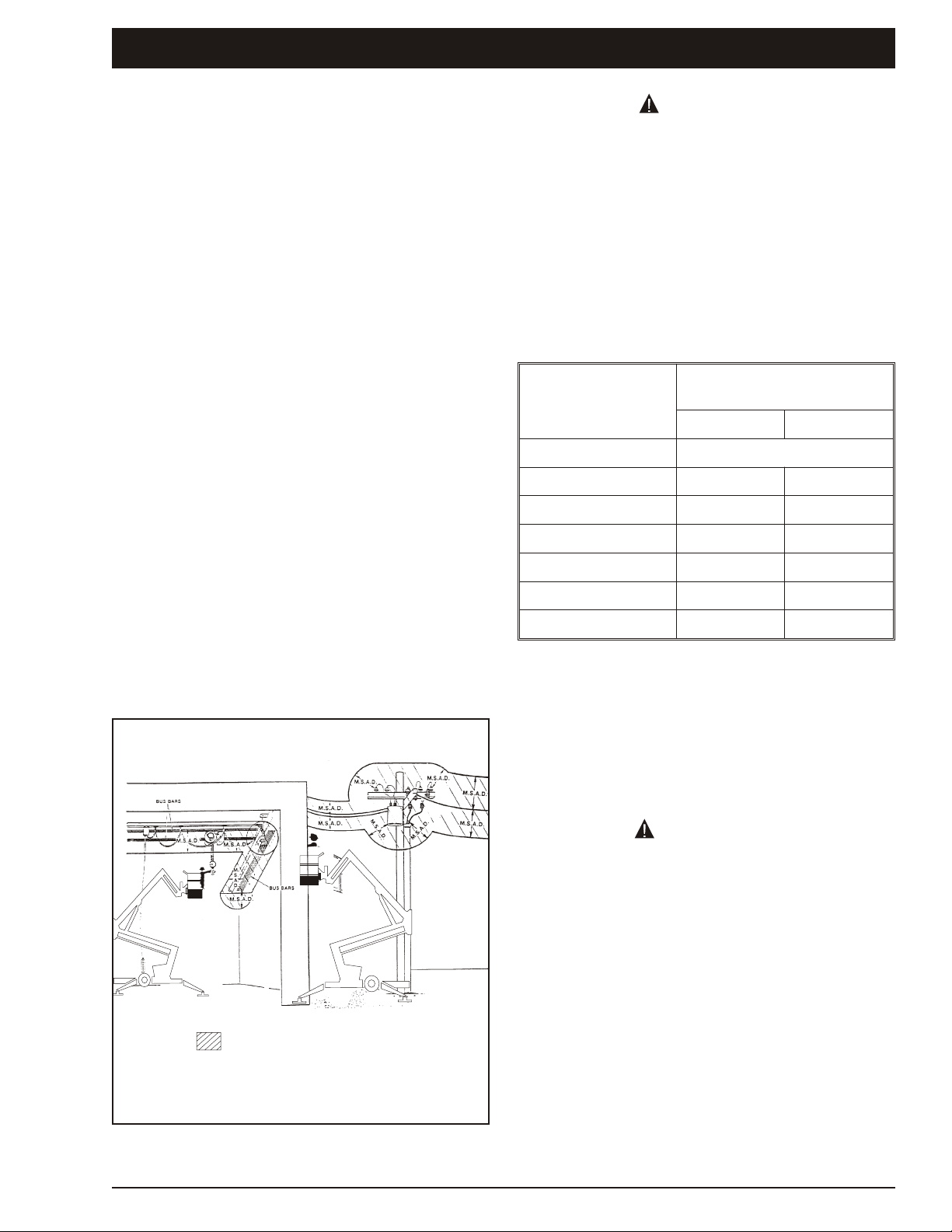
Denotes prohibited zone
Danger:
Caution:
- Do not allow machine personnel or conductive
materials inside prohibited zone.
- Maintain M.S.A.D. From all energised lines and parts
as well as those shown.
- Assume all electrical parts and wires are energised
unless known otherwise.
- Diagrams shown are only for purposes of illustrating
M.S.A.D. Work positions, not all work positions.
■
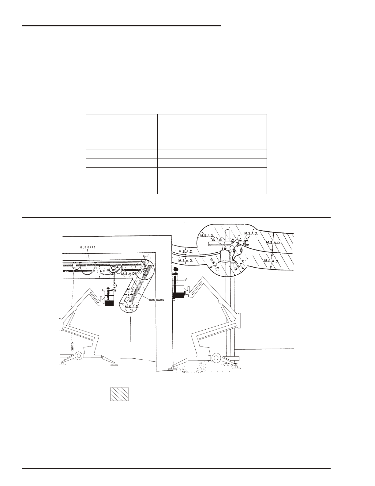
Minimum Safe Approach Distance
The MHP is an all metal boom, NOT ELECTRICALLY INSULATED, ae rial work plat form. DO NOT op er ate it near ELECTRICAL con duc tors. Re gard all con duc tors as be ing en er gized. Use the ta ble and il lus tra tion be low to de ter mine safe clear ance from elec tri cal con duc tors. (Ta ble 1 and Fig ure 3, be low, are from
ANSI/SIA A92.5–1992 Stan dard, re printed with per mis sion of Scaf fold In dus try As so ci a tion.)
❑ Table 1 - (M.S.A.D.)
Minimum Safe Approach Distance
to energized (exposed or insulated power lines)
Voltage range Minimum safe approach distance
(phase to phase)
0 to 300V
over 300v to 50kv
over 50kv to 200kv
over 200kv to 350kv
over 350kv to 500kv
over 500kv to 750kv
over 750kv to 1000kv
(Feet) (Meters)
Avoid contact
10
15
20
25
35
45
3.05
4.60
6.10
7.62
10.67
13.72
❑ Figure 3 - (M.S.A.D.)
page - ii MHP13/35 – 12431A
Page 5

Introduction
DANGER
WARNING
CAUTION
The most im por tant chap ter in this man ual is the
safety chap ter - Chap ter 1. Take time, now, to study
it closely. The in for ma tion in Chap ter 1, might save
your life, pre vent se ri ous in jury, or dam age to prop erty or the MHP13/35.
■
Standard MHP13/35
The stan dard MHP13/35 in cludes the fol low ing
fea tures:
●
Proportional speed control
●
Versatile jib boom
●
Heavy duty tow coupling
●
Heavy duty jockey wheel
●
Hydraulic disc brakes
●
High strength steel boom and base
construction
●
Reliable gasoline engine
●
Steel platform - 2 man capacity
●
600V AC rated wire to platform
●
Hour meter
●
Lockable hinged covers
●
Outrigger/boom interlocks
●
Independently operated hydraulic outriggers
●
Gravity gate
■
Options
The fol low ing op tions are avail able for the
MHP13/35:
Additional copies of this manual may be ordered
from Snorkel. Supply the model and manual part
number from the front cover to ensure that the
correct manual will be supplied.
All in for ma tion in this man ual is based on the lat est
prod uct in for ma tion at the time of pub li ca tion. Snor kel re serves the right to make prod uct changes at
any time with out ob li ga tion.
■
Safety Alerts
A safety alert sym bol is used through out this man ual to in di cate dan ger, warn ing and cau tion in struc tions. Fol low these in struc tions to re duce the
like li hood of per sonal in jury, prop erty dam age or
dam age to the ma chine.
The terms dan ger, warn ing, and cau tion in di cate
vary ing de grees of per sonal in jury or prop erty dam age that can re sult if the in struc tion is not fol lowed.
Denotes an imminently hazardous situation
which, if not avoided, will result in death or
serious injury.
Denotes a potentially hazardous situation
which, if not avoided, could result in death or
serious injury.
●
360o continuous rotation turntable
●
Flashing light
●
110/240V AC GFCI power to platform
●
Platform rotator
●
Lifting lugs
●
Automatic stabilisers
●
Alternative power options
❍
Alternative gasoline engine
❍
Diesel engine
❍
24V DC battery power
❍
110/240V AC motor and pump
❍
Combinations of the above with gas or
diesel to give a bi-energy power source
●
Sand blast protection kit
■
Operation Manual
This man ual pro vides in for ma tion for safe and
proper op er a tion of the ae rial plat form. Read and
un der stand the in for ma tion in this Op er a tor's man ual be fore op er at ing this ma chine on a job site.
Denotes a potentially hazardous situation
which, if not avoided, may result in minor or
moderate injury.
It may also be used to alert against unsafe
practices or action which may result in
damage to the MHP.
Notes
Notes are used to pro vide spe cial in for ma tion or
help ful hints to as sist in ae rial plat form op er a tion,
but do not in di cate a haz ard ous sit u a tion.
■
Operation
The MHP ae rial plat form has built in safety fea tures
and has been fac tory tested for com pli ance with
Snor kel spec i fi ca tions and in dus try stan dards.
How ever, any per son nel lift ing de vice can be po ten tially dan ger ous in the hands of un trained or
care less op er a tors.
Training is vi tally im por tant and must be performed
un der the di rec tion of a QUALIFIED per son. You
must dis play pro fi ciency in knowl edge and ac tual
op er a tion of the MHP be fore us ing it on a job site.
MHP13/35 – 12431A page - iii
Page 6

Introduction
WARNING
WARNING
Be fore op er a tion of the MHP you must read and un der stand the op er at ing in struc tions in this man ual
as well as the de cals, warn ings, and in struc tions on
the ma chine it self.
Be fore op er at ing the MHP you must be
AUTHORIZED by the per son in charge to do so
and the op er a tion of the MHP must be within the
scope of the ma chine spec i fi ca tions.
The potential for an accident increases when
the aerial platform is operated by personnel
who are not trained and authorised. Death or
serious injury can result from such
accidents. read and understand the
information in this manual and on the
placards and decals on the machine before
operating the MHP on the job site.
■
Maintenance
Ev ery per son who main tains, in spects, tests, or re pairs these ma chines, and ev ery per son su per vis ing any of these func tions, must be prop erly trained
and qual i fied to do so.
This Op er a tor’s Man ual pro vides a daily in spec tion
pro ce dure that will help you keep your MHP in good
op er at ing con di tion.
Do not per form other main te nance un less you are a
trained me chanic, qualified to work on the MHP.
Call qualified main te nance per son nel if you find
prob lems or mal func tions.
Do not mod ify this ma chine with out writ ten ap proval from the En gi neer ing De part ment of Snor kel. Mod i fi ca tion may void the war ranty, ad versely
af fect sta bil ity, or af fect the op er a tional char ac ter is tics of the MHP.
■
Responsibilities of parties
It is im per a tive that all own ers and us ers of the
MHP read, un der stand, and con form to all ap pli ca ble reg u la tions. Ul ti mate com pli ance to OSHA reg u la tions is the re spon si bil ity of the user and their
em ployer.
A re print of the “Man ual of Re spon si bil ities for
Dealers, Owners, Users, Op er a tors, Les sors and
Les sees of ANSI/SIA A92.5-1992 Boom Sup ported El e vating Work Plat forms” is avail able from
Snor kel deal ers or from the fac tory upon re quest.
Copies are also avail able from:
Scaf fold In dus try As so ci a tion, Inc.,
P.O. Box 1160
Phoe nix, AZ 85036-0574 USA
■
In summary
●
Only trained and authorised operators should
be permitted to operate the equipment.
●
All manufacturer’s operating instructions and
safety rules and all employers’ safety rules
and all OSHA and other government safety
rules should be strictly adhered to.
●
Repairs and adjustments should be made
only by qualified and trained maintenance
personnel.
●
No modification should be made to the
equipment without prior written consent of
the Snorkel Engineering Department.
●
Make a pre-start inspection of the MHP at
the beginning of each shift. A malfunctioning
machine must not be used.
●
Make an inspection of the work place to
locate possible hazards before operating the
MHP.
■
Additional information
For ad di tional in for ma tion, con tact your lo cal
dealer or Snor kel at:
Snor kel International
2/26 Red fern Street
Wether ill Park NSW 2164
Aus tra lia
Snor kel International
PO Box 1041
Levin 5500
New Zea land
ANSI Stan dard A92.2-2001clearly iden ti fies
re quire ments of all par ties who might be
in volved with Boom-Sup ported El e vat ing
Work Plat forms.
AUSTRALIAN / NZ STANDARD 2550-10 1994
Also iden ti fies the re quire ments of all
par ties who might be in volved with
Boom-Sup ported El e vat ing Work Plat forms.
page - iv MHP13/35 – 12431A
Page 7

Table of Contents
Electrical Hazard
Electrical Hazard Warning ..................i
Minimum Safe Approach Distance ...........ii
Table 1 - (M.S.A.D.) .....................ii
Figure 3 - (M.S.A.D.) ....................ii
Introduction
Standard MHP13/35......................iii
Options................................iii
Operation Manual........................iii
Safety Alerts............................iii
Operation ..............................iii
Maintenance ...........................iv
Responsibilities of parties .................iv
In summary ............................iv
Additional information ....................iv
1. Safety
Safe Operation ........................1-1
Electrocution Hazards ...................1-1
Minimum safe approach distance .........1-1
Pre-start Inspection .....................1-1
Work Place Inspection and Practices .......1-1
Operation.............................1-2
Tipover and Falling Hazards ..............1-3
General Safety Precautions ..............1-3
Hydraulic System Precautions ............1-3
Fire Prevention ........................1-3
Engine and Fuel Handling Precautions......1-4
Batteries .............................1-4
Safety Decals and Placards ..............1-4
2. Safety Devices
Safety Device Information ................2-1
Emergency Stop Switches ...............2-1
At ground control box ..................2-1
At platform control box .................2-1
Other Safety Devices ...................2-1
Lanyard anchor points .................2-1
Gravity gate..........................2-2
Guardrails ...........................2-2
Foot switch ..........................2-2
Bubble level .........................2-2
RCD/ELCB AC outlet ..................2-3
Flashing light.........................2-3
3. Specifications
General Specifications ..................3-1
Recommended Hydraulic Oil..............3-2
Engine Data...........................3-2
Overall Dimensions - MPH13/35...........3-3
Working Envelope - MHP13/35............3-4
Booms identification ...................3-5
Nomenclature And Serial Numbers.........3-5
Right side view of machine ..............3-5
Left side view of machine ...............3-6
4. Gauges
Hourmeter ............................4-1
Level Bubble ..........................4-1
Hydraulic Oil Level .....................4-1
5. Automatic Shut-offs and Circuit Breakers
RCD/ELCB Outlet (option) ...............5-1
Main Circuit Breaker ....................5-1
Outriggers ............................5-1
6. Controls
Controls Description ....................6-1
Controls and Control Decals Locations ....6-1
Ground Control Box.....................6-2
Lower controls: .......................6-2
Ground Control Box Controls ............6-2
Platform Control Box ....................6-3
Upper controls: .......................6-3
Stabiliser Controls ......................6-4
Self Levelling Stabilisers (Option) ..........6-4
7. Daily Inspection and Maintenance
Daily Inspection and Maintenance Table ....7-1
Engine Fuel Level ......................7-2
Fuel Tank Cap.........................7-2
Fuel Leaks............................7-2
Engine Oil Level .......................7-2
Operator's Manual......................7-2
Wiring Harnesses ......................7-2
Battery Terminals ......................7-3
Battery Fluid Level......................7-3
Hydraulic Oil Level .....................7-3
Hydraulic Oil Leaks .....................7-3
Bolts and Fasteners ....................7-4
Wheels and Tyres ......................7-4
Structural Damage and Welds ............7-4
Lanyard Anchor Points ..................7-5
Platform Gravity Gate ...................7-5
Platform Guardrails .....................7-5
Flashing Light (option)...................7-5
Ground Control Switches ................7-6
Emergency Lower ......................7-6
Lower control box .....................7-6
Upper control box .....................7-6
Platform Control Switches ...............7-6
AC Outlet RCD/ELCB (option) ............7-7
Placards and Decals ....................7-7
Standard placards and decals ...........7-7
Inspection drawing ....................7-8
MHP13/35 – 12431A page - v
Page 8

Table of Contents
8. Operation
Operating Procedures ...................8-1
Control Stations........................8-1
Emergency Stopping
Lower Control Box......................8-1
Emergency Stopping
Upper Control Box......................8-1
Operation Considerations ................8-2
Starting From Ground Control Box .........8-2
Stabiliser Operation.....................8-2
Self Levelling Stabilisers (Option) ..........8-2
Setting the stabilisers manually ..........8-3
Starting From Platform Control Box ........8-3
Moving The Platform ....................8-4
From Ground Control Box...............8-4
From Platform Control Box ..............8-5
Securing for Day .......................8-5
9. Emergency Operation
Emergency Operation Procedures .........9-1
Operation From Platform Control Box......9-1
Operation From Ground Control Box ......9-2
10. Stowing and Transporting
Stowing .............................10-1
The correct stowed position is shown here. 10-1
Transporting .........................10-1
Trailering ...........................10-1
Securing to a Transport Vehicle .........10-2
Towing..............................10-2
Forklift points........................10-2
11. Options
Air Line To Platform....................11-1
Dual Fuel ............................11-1
24V DC Battery Power .................11-1
Bi-Energy............................11-1
Work Lights ..........................11-1
Flashing Light ........................11-1
RCD/ELCB AC Outlet ..................11-1
Sandblast Protection Kit ................11-1
Platform Rotator ......................11-1
12. Fire Fighting and Chemical Containment
Hazardous Components ................12-1
Battery, Lead/Acid (UN 2794) ...........12-1
Gasoline (UN 1203) ..................12-2
Hydraulic Oil (UN 1270) ...............12-3
Motor Oil (UN 1270) ..................12-3
13. Operator's Troubleshooting
Troubleshooting.......................13-1
Operator Troubleshooting Chart .........13-1
page - vi MHP13/35 – 12431A
Page 9
■
WARNING
DANGER
Denotes prohibited zone
Caution:
- Diagrams shown are only for purposes of illustrating
M.S.A.D. Work positions, not all work positions.
Safe Operation
Knowl edge of the in for ma tion in this man ual, and
proper train ing, pro vide a ba sis for safely op er at ing
the MHP13/35. Know the lo ca tion of all the con trols
and how they op er ate to act quickly and re spon si bly in an emer gency.
Safety de vices re duce the like li hood of an ac ci dent. Never dis able, mod ify, or ig nore any safety
de vice. Safety alerts in this man ual in di cate sit u a tions where ac ci dents may oc cur.
If any mal func tion, haz ard or po ten tially un safe
con di tion re lat ing to ca pac ity, in tended use, or safe
op er a tion is sus pected, stop the op er a tion of the
MHP and seek as sis tance.
The op er a tor bears ul ti mate re spon si bil ity for fol low ing all man u fac tur ers in struc tions and warn ings, reg u la tions and safety rules of their em ployer
and/or any coun try or re gional law.
1. Safety
The MHP is not electrically insulated. Death
or serious injury can result from contact
with, or inadequate clearance from, an
energised conductor. Do not go closer than
the minimum safe approach distance as
defined by ANSI.
ANSI pub li ca tions de fine min i mum dis tances that
must be ob served when work ing near bus bars and
energised power lines. Fig ure 1 and Ta ble 1 are re printed cour tesy of the Scaf fold in dus try As so ci a tion, ANSI/SIA A92.5.
Voltage Range
(Phase to Phase
0 to 300V
Minimum Safe Approach
Distance
Feet Metres
Avoid Contact
■
Electrocution Hazards
The MHP is an all metal boom ae rial work plat form
and is not elec tri cally in su lated. Do not op er ate it
near electrical con duc tors. Re gard all con duc tors
as be ing en er gized. Do not op er ate out side dur ing
a thun der storm.
❑ Minimum safe approach distance
Min i mum safe ap proach dis tances to energised
power lines and their as so ci ated parts must be ob served wile op er at ing the MHP.
Over 300V to 50kV
Over 50kV to 200kV
Over 200kV to 350kV
Over 350kV to 500kV
Over 500kV to 750kV
Over 750kV to 1000kV
10 3.05
15 4.60
20 6.10
25 7.62
35 10.7
45 13.72
Table 1. - Minimum Safe Approach Distance
■
Pre-start Inspection
At the start of each work shift, the MHP13/35 shall
be given a vi sual in spec tion and func tion test. See
the “Daily In spec tion and Main te nance” chap ter 7,
in this man ual for a list of items to in spect and test.
DO NOT operate the MHP13/35 unless you
are trained and authorized, understand the
operation characteristics of the MHP13/35,
and have inspected and tested all functions
to be sure they are in proper working order.
■
Work Place Inspection and Practices
Do not use the MHP13/35 as a ground for weld ing.
Ground to the work piece.
Be fore the MHP13/35 is used, and dur ing use,
check the area in which the MHP13/35 is to be used
for pos si ble haz ards such as, but not lim ited to:
●
Drop-offs or holes.
Figure 1. - Minimum Safe Approach Distance
MHP13/35 – 12431A page 1 - 1
●
Side slopes.
Page 10

1. Safety
DANGER
●
Bumps and floor obstructions.
●
Debris.
●
Overhead obstructions and electrical
conductors.
●
Hazardous locations.
●
Inadequate surface and support to withstand
all load forces imposed by the aerial platform
in all operating configurations.
●
Wind and weather conditions.
●
Presence of unauthorized persons.
●
Other possible unsafe conditions.
Be fore the MHP13/35 is used, de ter mine the haz ard
clas si fi ca tion of any par tic u lar at mo sphere or lo ca tion ac cord ing to ANSI/NFPA 505-1987.
Any MHP13/35 op er ated in a haz ard ous lo ca tion
must be ap proved and of the type re quired by
ANSI/NFPA 505-1987.
While operating the MHP a recommended safety
practice is to have trained and qualified personnel
in the immediate work area of the MHP13/35 to:
●
Help in case of an emergency.
●
Operate emergency controls as required.
●
Watch for loss of control by platform
operator.
●
Warn the operator of any obstructions or
hazards that may not be obvious to them.
●
Watch for soft terrain, sloping surfaces,
drop-offs, etc., where stability could be
jeopardized.
●
Watch for bystanders and never allow
anyone to be under, or to reach through the
booms while operating the aerial platform.
Al ways look in the di rec tion of travel. Drive with
care and at speeds com pat i ble with the work-place
con di tions. Use cau tion when driv ing over rough
ground, on slopes, and when turn ing.
Do not en gage in any form of “horse play” or “stunt
driv ing” while op er at ing the MHP13/35.
Do not per mit rid ers on the ma chine any place other
than on the plat form.
Re move all loose ob jects stored in or on the ma chine, par tic u larly in the plat form. Re move all ob jects which do not be long in or on the ma chine.
Never steady the plat form by po si tion ing it against
an other plat form.
Do not op er ate an MHP13/35 that is dam aged or
not func tion ing prop erly. Do not use the MHP until
the ma chine has been re paired by a qual i fied main te nance per son.
Do not op er ate a MHP13/35 that does not have all
its de cals and plac ards at tached and leg i ble.
Watch for by stand ers and never al low any one to be
un der, or to reach through, the ma chine and its
equip ment while op er at ing.
Use the rec om mended trans port de vice when
load ing the ma chine.
■
Operation
If you en coun ter any sus pected mal func tion of the
ae rial plat form, or any haz ard or po ten tially un safe
con di tion re lat ing to ca pac ity, in tended use, or safe
op er a tion, cease op er a tion im me di ately and seek
as sis tance from man age ment.
Use three points of sup port when get ting on or off
the plat form (two hands and one foot or a sim i lar set
of points). Keep the plat form clean.
Main tain a firm foot ing on the plat form floor. Op er -
Pinch points may exist between moving
components. Death or serious injury can
result from becoming trapped between
components, buildings, structures, or other
obstacles. Make sure there is sufficient
clearance around the machine before
ate the con trols slowly and de lib er ately to avoid
jerky and er ratic op er a tion. Al ways stop the con trols in neu tral be fore go ing in the op po site di rec tion.
Do not dis mount while the plat form is in mo tion or
jump off the ma chine.
moving the chassis, booms, or platform.
Allow sufficient room and time to stop
movement to avoid contact with structures
or other hazards.
Keep ground per son nel from un der the plat form
when the plat form is raised.
Do not start un til all per son nel are clearly away
from the ma chine.
Never cover the floor grat ing or oth er wise ob struct
your view be low. Make sure the area be low the
plat form is free of per son nel be fore low er ing.
Se cure all ac ces so ries, con tain ers, tools, and
other ma te ri als in the plat form to pre vent them from
ac ci den tally fall ing or be ing kicked off the plat form.
page 1 - 2 MHP13/35 – 12431A
Page 11

1. Safety
DANGER
DANGER
■
Tipover and Falling Hazards
Operate the MHP only on a firm, flat, level surface
capable of withstanding all load forces imposed by
the MHP13/35 in all operating conditions.
The MHP can tip over if it becomes unstable.
Death or serious injury can result from a
tip-over accident. Do not drive or position
the MHP platform for elevated use near any
drop-ff, hole, slope, soft or uneven ground,
or other tip-over hazard.
Do not op er ate the MHP13/35 from a po si tion on
trucks, trail ers, rail way cars, float ing ves sels, scaf folds, or sim i lar equip ment un less the ap pli ca tion is
ap proved in writ ing by Snor kel.
Care shall be taken to prevent rope, electric cords,
and hoses, etc., from becoming entangled in the
aerial platform. If the platform or elevating
assembly becomes caught, snagged, or otherwise
prevented from normal motion by an adjacent
structure or other obstacle such that control
reversal does not free the platform, remove all
personnel from the platform before attempts are
made to free the platform using ground controls.
Do not climb on the guardrails or use ladders,
planks, or other devices to extend or increase your
work position from the platform.
Do not use the MHP as a crane, hoist, or jack,or for
any other pur pose other than to po si tion per son nel,
their tools, and ma te ri als.
Do not op er ate the MHP13/35 in winds, or wind
gusts, of 28 mph, 45kph 12.5 m/s) or more and do
not add any thing to the MHP13/35 that will in crease the wind load ing (ban ners, flags, etc.).
■
General Safety Precautions
Do not mod ify the MHP13/35 in any way.
When parts or com po nents are re placed, they shall
be iden ti cal or equiv a lent to orig i nal Snor kel parts
or com po nents.
Do not over ride any of the safety fea tures of the
MHP13/35.
■
Hydraulic System Precautions
The hy drau lic sys tem con tains hoses with hy drau lic fluid un der pres sure.
Un der nor mal work ing con di tions it is best not to
trans fer from the plat form to an other struc ture or
vice versa, un less that is the saf est way to do the
job. Each sit u a tion must be judged sep a rately tak ing the work en vi ron ment into ac count. The fol low ing guide lines ap ply:
1. Where possible, place the work platform over
a roof or walking structure to do the transfer.
2. Transfer your anchorage from one structure
to another before you step across.
3. Remember, you might be departing the work
platform to a structure where fall arrest is
required.
4. Do not climb over or through the guardrails.
Use the platform entrance.
All plat form oc cu pants MUST wear and use fall re straint. At tach fall re straints to the plat form lan yard
an chor points.
Do not ex ceed the un re stricted plat form ca pac ity
as in di cated on the ca pac ity plac ard at the en trance to the plat form. Do not carry loads from any
point out side of the plat form.
Make sure that all pro tec tive guards, cowl ings, and
doors are in place and se cure. Be sure the guard rail sys tem, in clud ing the gate, is in place and se cure.
Hydraulic fluid escaping under pressure can
have enough force to inject fluid into the
flesh. Serious infection or reaction can
result if medical treatment is not given
immediately. In case of injury by escaping
hydraulic fluid, seek medical attention at
once.
DO NOT place your hand or any part of your body in
front of es cap ing hy drau lic fluid. Use a piece of
card board or wood to search for hy drau lic leaks.
Do not at tempt re pairs to hy drau lic sys tems un less
you are trained. Re fer to ex pe ri enced re pair per son nel for help.
■
Fire Prevention
Never op er ate your MHP near a flame or spark. Hy drau lic oil and gas o line are flam ma ble and can ex plode.
NOTE:
This ma chine is equipped with an in ter nal com bus tion en gine (in it's stan dard con fig u ra tion) and
should not be used on or near any un im proved
for est-cov ered, brush-cov ered or grass cov ered
land un less the en gine's ex haust sys tem is
equipped with a spark ar rester meet ing ap pli ca ble laws. If a spark ar rester is used, it should be
MHP13/35 – 12431A page 1 - 3
Page 12
1. Safety
WARNING
CAUTION
DANGER
DANGER
CAUTION
main tained in ef fec tive work ing order by the
operator.
■
Engine and Fuel Handling Precautions
Engine exhaust contains carbon monoxide,
a poisonous gas that is invisible and
odorless. Breathing engine exhaust fumes
can cause death or serious illness. Do not
run the engine in an enclosed area or
indoors without adequate ventilation.
Only re fuel your MHP out doors in a clear area void
of gas fumes or spilled gas.
Never re move the fuel cap or re fuel a gas o line en gine while the en gine is run ning or hot. ALWAYS al low the en gine to cool be fore re fu el ing. Never al low
fuel to spill on hot ma chine com po nents.
DO NOT smoke or permit open flames while
fueling or near fueling operations.
Main tain con trol of the fuel filler noz zle when fill ing
the tank.
area of the spill and avoid creating any source of
ignition until the spilled fuel has evaporated.
Tighten the fuel tank cap se curely. If the fuel cap is
lost, re place it with an ap proved cap from Snor kel.
Use of a non-ap proved cap with out proper vent ing
may re sult in pres sur iza tion of the tank.
Never use fuel for clean ing pur poses.
For die sel en gines, use the cor rect fuel grade for
the op er at ing sea son.
■
Batteries
Charge bat ter ies in a well ven ti lated area free of
flame, sparks, or other haz ards that might cause
fire or ex plo sion.
Batteries give off hydrogen and oxygen that
can combine explosively. Death or serious
injury can result from a chemical explosion.
Do not smoke or permit open flames or
sparks when checking batteries.
Battery acid can damage the skin and eyes.
Serious infection or reaction can result if
medical treatment is not given immediately.
Wear face and eye protection when working
near batteries.
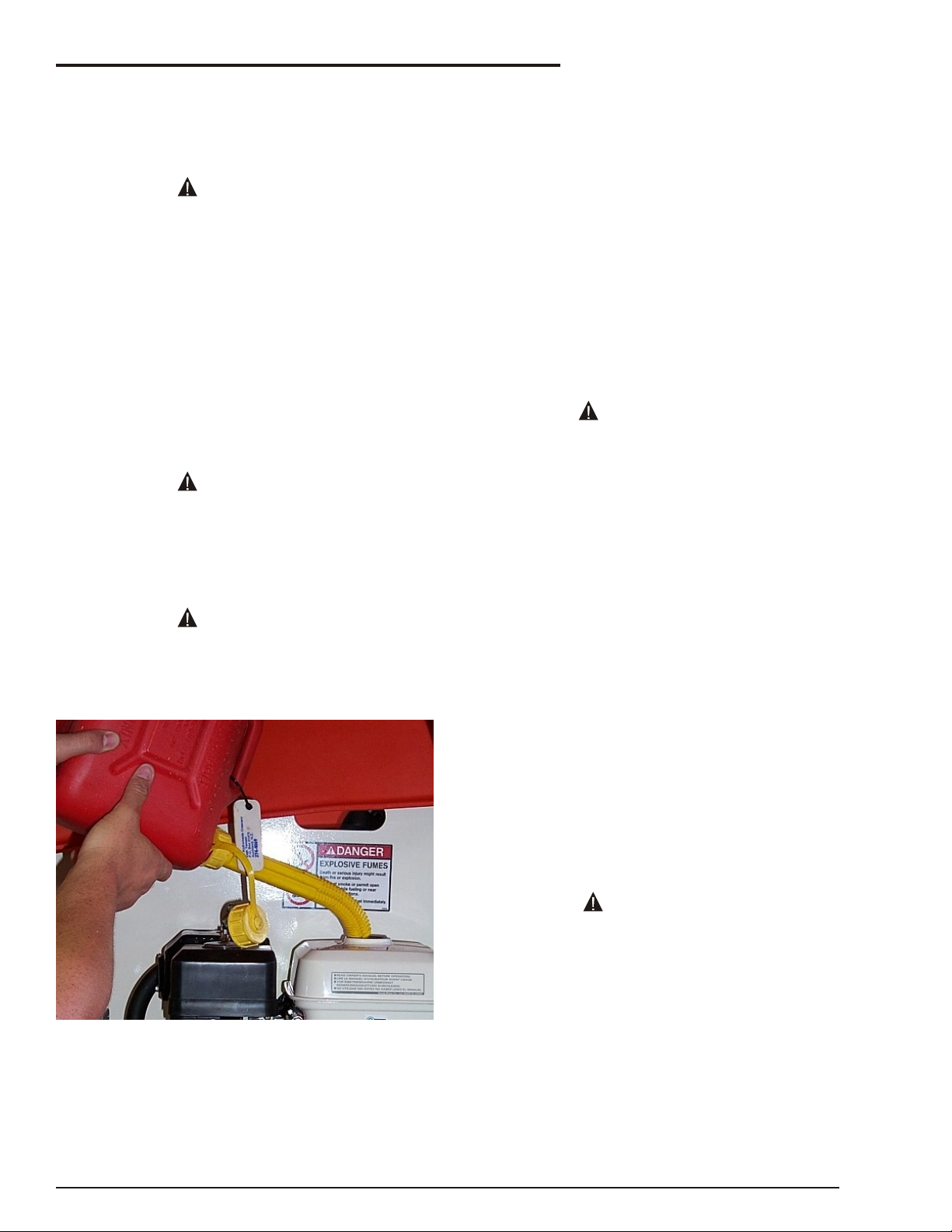
ENSURE you use an approved fuel container
with appropriate fuel filler nozzle (see
picture below)
Correct Method to Fill MHP13/35 Fuel Tank
Do not fill the fuel tank to ca pac ity. Al low room for
ex pan sion.
If gasoline is spilled, clean up spilled fuel
immediately, push/tow the MHP away from the
Bat ter ies con tain sul fu ric acid that can dam age
your eyes or skin on con tact. Wear a face shield,
rub ber gloves, and pro tec tive cloth ing when work ing around bat ter ies. If acid con tacts your eyes,
flush im me di ately with clear wa ter and get med i cal
at ten tion. If acid con tacts your skin, wash off im me di ately with clear wa ter.
■
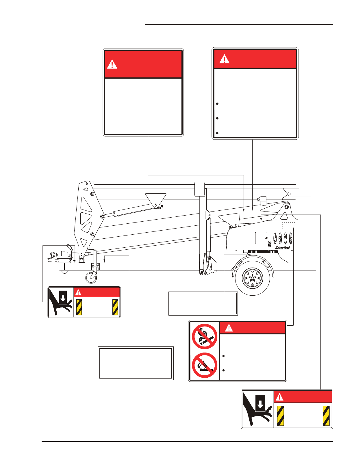
Safety Decals and Placards
There are sev eral safety de cals and plac ards on
the MHP13/35. Their lo ca tions and de scrip tions
are shown in this sec tion. Take time to study them.
Be sure that all the safety decals and
placards on the MHP13/35 are legible. Clean
or replace them if you cannot read the words
or see the pictures. Clean with soap & water
and a soft cloth. Do not use solvents.
You MUST replace a decal or placard if it is
damaged, missing, or cannot be read. If it is
on a part that is replaced, make sure a new
decal or placard is installed on the replaced
part. See your Snorkel dealer for new decals
and placards.
page 1 - 4 MHP13/35 – 12431A
Page 13
1. Safety
DANGER
PINCH POINT
Keep hands
clear.
302559
DANGER
PINCH POINT
Keep hands
clear.
302559
DANGER
EXPLOSIVE FUMES
Clean up spilled fuel
immediately.
Do not smoke or permit open
flames while fueling or near
fueling operations.
Death or serious injury might result
from fire or explosion.
476706
FIT BOOM CRADLE LOCK PIN
FOR TRAVELLING.
1772-002K
TYRE
PRESSURE
45
p.s.i.
310
kPa
COLD
7856-45
YOU MUST NOT OPERATE THIS DEVICE UNLESS:
AN UNTRAINED OPERATOR SUBJECTS HIMSELF AND OTHERS TO
DEATH OR SERIOUS INJURY.
0323897
1.
2.
YOU HAVE BEEN TRAINED IN THE SAFE OPERATION OF THIS
DEVICE AND HHHH
YOU KNOW AND FOLLOW THE SAFETY AND OPERATING
RECOMMENDATIONS CONTAINED IN THE MANUFACTURER'S
MANUALS, YOUR EMPLOYER'S WORK RULES, AND APPLICABLE GOVERNMENTAL REGULATIONS. HHHHHHHH
DANGER
DANGER
ELECTROCUTION
HAZARD
THIS MACHINE IS NOT
ELECTRICALLY INSULATED.
0323899
Death or serious injury can result from
contact or inadequate clearance to
electrical power lines and apparatus.
Maintain 10 feet minimum clearance
from electrical power lines and
apparatus.
Allow for sway, rock, and sag.
MHP13/35 – 12431A page 1 - 5
Page 14
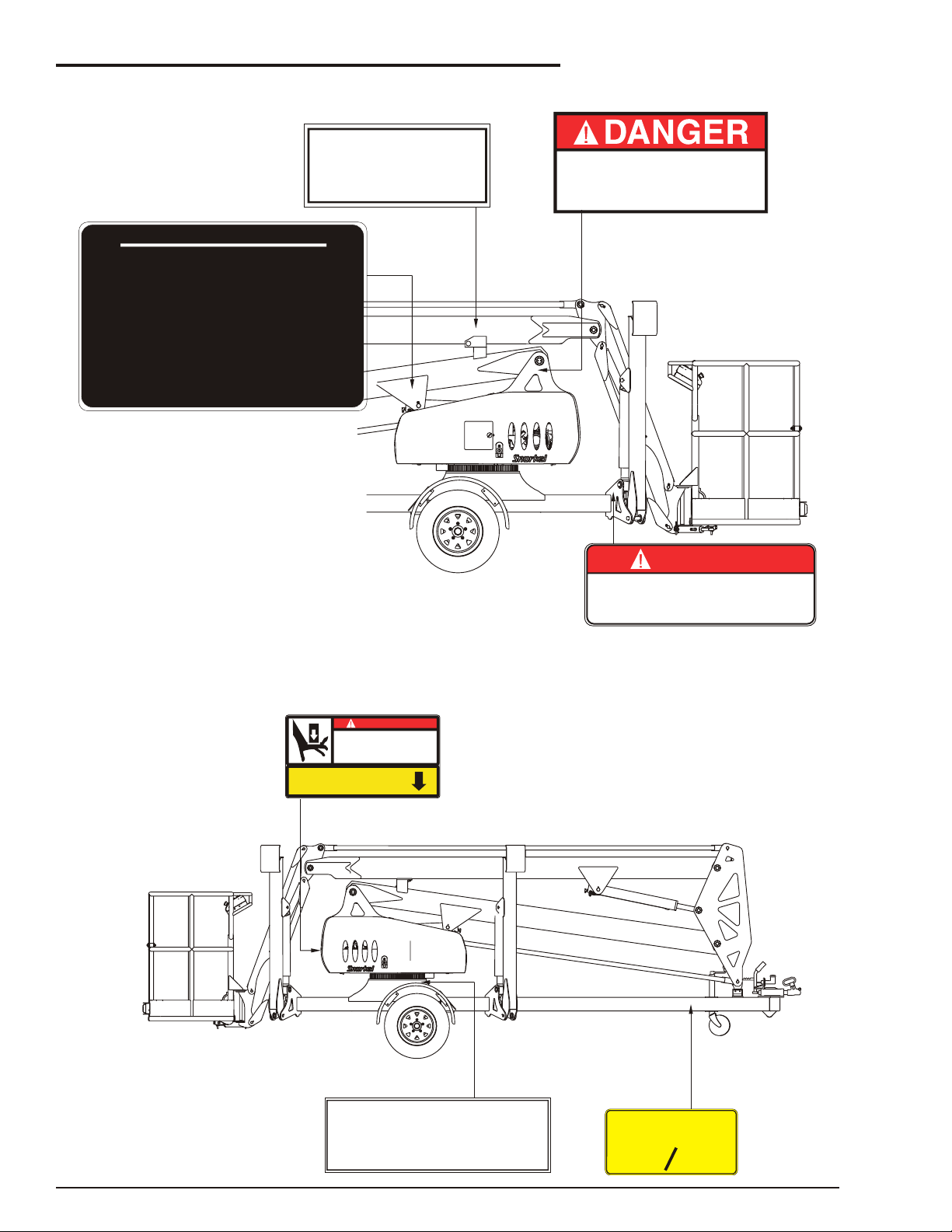
1. Safety
KEEP CLEAR OF DESCENDING BOOM
DEATH OR SERIOUS INJURY CAN
OCCUR FROM DESCENDING BOOM
0150602
DANGER
DO NOT ALTER OR DISABLE
LIMIT SWITCHES, SAFETY
SWITCHES, OR INTERLOCKS.
451986
ALL FOUR
STABLIZERS
TYRE
PRESSURE
45
p.s.i.
310
kPa
COLD
7856-45
EMERGENCY BLEED
DOWN VALVE
CRUSHING HAZARD
Death or serious injury might result from
having body parts crushed as the
boom/platform descends. Keep out from
under the descending boom and platform.
DANGER
12406
OPERATORS CHECKLIST
INSPECT AND/OR TEST THE FOLLOWING DAILY
OR AT THE BEGINNING OF EACH SHIFT
1. OPERATING AND EMERGENCY CONTROLS.
5. CABLES AND WIRING HARNESS.
6. LOOSE OR MISSING PARTS.
7. TYRES AND WHEELS.
8. PLACARDS, WARNINGS, CONTROL MARKINGS
AND OPERATING MANUAL(S).
9. GUARDRAIL SYSTEM.
10.OIL LEVELS.
11.BATTERY FLUID LEVEL.
4. HOSES, FITTINGS AND VALVES FOR LEAKS.
3. PERSONAL PROTECTIVE DEVICES.
2. SAFETY DEVICES.
300699
TOWING SPEED
80
KPH
12424
50
MPH
MAXIMUM
FIT BOOM CRADLE LOCK PIN
FOR TRAVELLING.
1772-002K
page 1 - 6 MHP13/35 – 12431A
Page 15
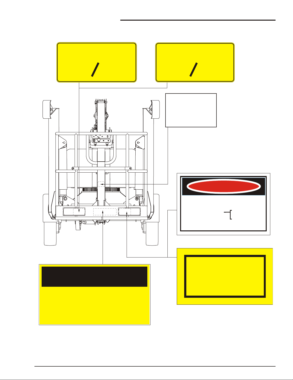
WARNING
KEEP LINESCLEAR POWEROF
Unless the Electrical Supply Authority has advised
in writing otherwise;
the clearance between any live overhead
power line and any part of this machine or
load carried is required by law to be
AT LEAST 4 METRES
This is a requirement of regulation 93 of the
Electrical Supply Regulations 1984
in the interests of safe working.
DANGER
BEWARE OF ELECTRICAL HAZARDS
REGULATION 133A OF THE
CONSTRUCTION SAFETY ACT 1912 REQUIRES
(a) Minimum approach of an appliance
(b) Inspection of the work site for
(c) Constant vigilance and an observer required
to live electrical apparatus.
electrical hazards before
commencing to use the appliance.
whilst working or travelling the appliance
in the vicinity of live electrical apparatus.
3m. for voltages up to 132,000
6m. for voltages above 132,000
and up to 330,000
8m. for voltages above 330,000
(New Zealand Only)
(Australia Only)
CAUTION
EACH PERSON ON THE PLATFORM
MUST WEAR A FULL SAFETY HARNESS
WITH LEG STRAPS
AND ENERGY ABSORBING LANYARD
ATTACHED TO AN APPROVED ANCHOR
POINT IN THE PLATFORM
99228-1
RATED LOAD
440
LB
12423-200
200
KG
Attach lanyard
of fall restraint
to loop below
0150448
RATED LOAD
500
LB
12423-227
227
KG
Note: Rated capacity depends on the configuration of the machine
see Chapter 3 - Specifications
1. Safety
NOTE:
Refer to Placards and Decals Inspection Chart and Drawing in the “Daily Inspection and
Maintenance” chapter 7, for part numbers, location, and required quantities of all placards and
decals.
MHP13/35 – 12431A page 1 - 7
Page 16
■
WARNING
Safety Device Information
For emer gency op er a tion con trols and pro ce dures,
see the “Emer gency Op er a tion” chap ter 9, in this
man ual.
The de vices listed in this chap ter are safety de vices.
They are on the MHP13/35 to in crease safety in the
work place for both the op er a tor and other peo ple
near the MHP13/35.
DO NOT by pass, disable, modify, or ignore
any of these devices. Check them carefully
at the start of each work shift to see that they
are in working order (see “Daily Inspection
and Maintenance” chapter 7). If any is found
to be defective, remove the MHP13/35 from
service immediately until a qualified service
technician can make repairs.
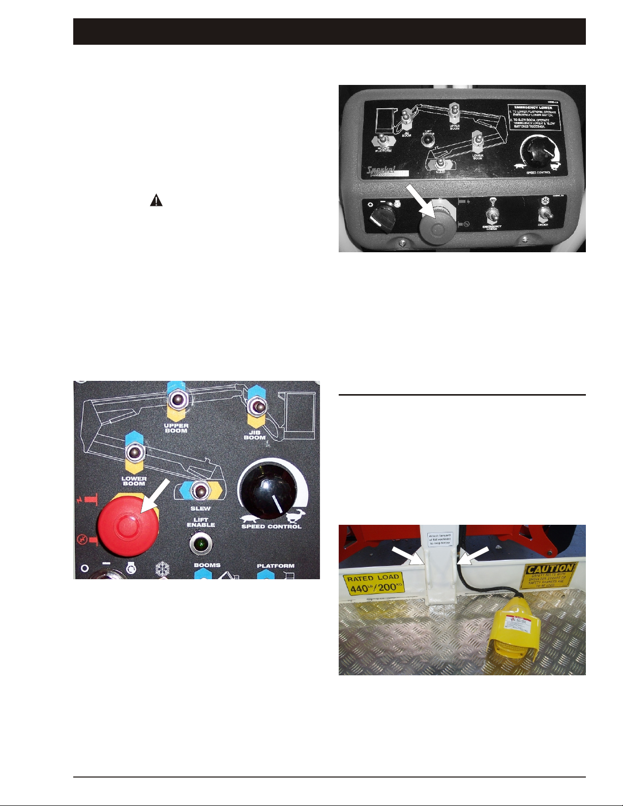
■
Emergency Stop Switches
❑ At ground control box
2. Safety Devices
❑ At platform control box
Figure 2.2 - Emergency Stop Switch at
Platform Control Box
Press the large red EMERGENCY STOP switch in,
at any time, un der any con di tions and the en tire
ma chine stops, and noth ing moves. This emer gency stop switch must be out (on) to control the
MHP13/35 from the plat form (pull the switch and it
will pop out).
Figure 2.1 - Emergency Stop Switch at
Ground Control Box
Press the large red EMERGENCY STOP switch in,
at any time, un der any con di tions and the en tire
ma chine stops, and noth ing moves. This emer gency stop switch must be out (on) for any thing on
the MHP13/35 to work. Pull the switch and it will
pop out.
NOTE:
The ground control box is designed to override
the platform control box. If the platform control
box EMERGENCY STOP switch is in (off) the
ground con trol box can still be used to start and
op er ate the MHP13/35.
■
Other Safety Devices
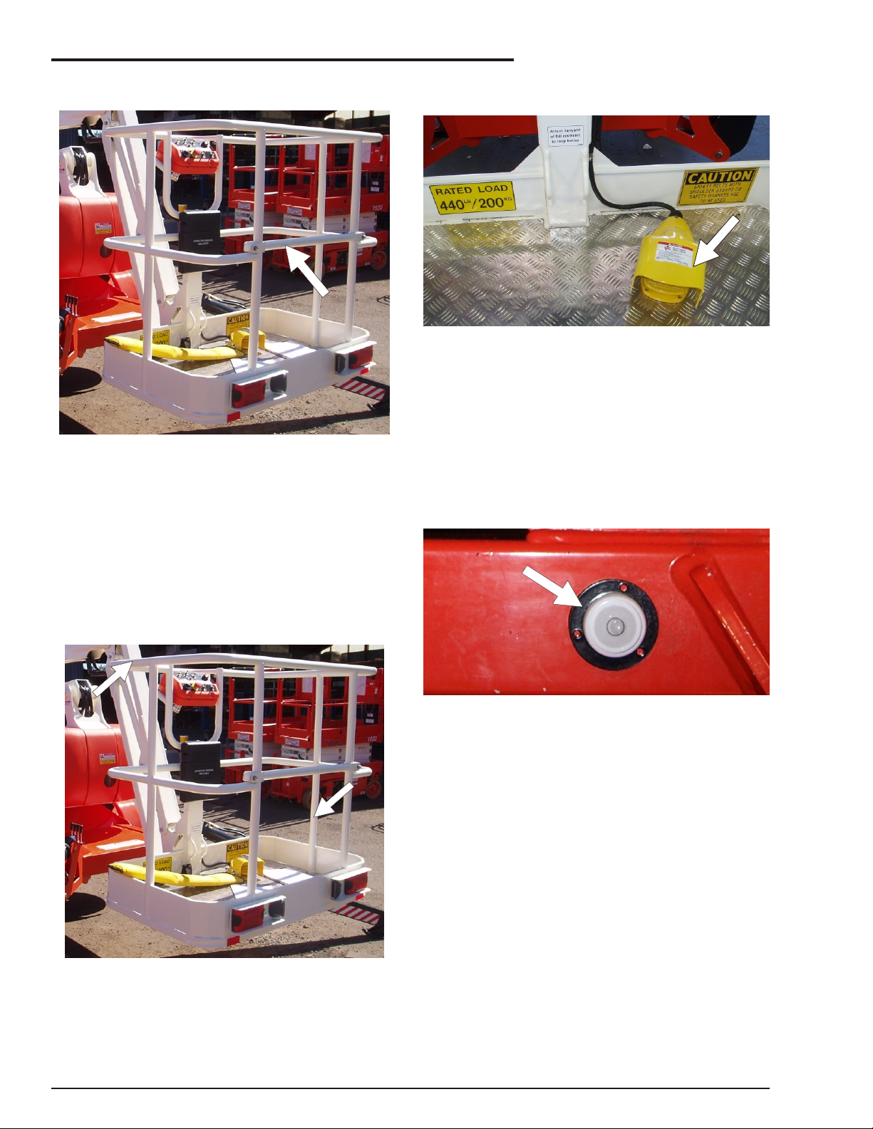
❑ Lanyard anchor points
Figure 2.3 - Lanyard Anchor Points
All personnel on the platform should attach their fall
restraint lanyards to one of the lanyard anchor
points.
MHP13/35 – 12431A page 2 - 1
Page 17
2. Safety Devices
❑ Gravity gate
Figure 2.4 - Gravity Gate
The grav ity gate is the place in the plat form guard rail sys tem where you should en ter and leave the
plat form. Raise the gate and step un der it onto the
plat form. Once you have en tered the plat form and
at tached your fall re straint lan yard to an an chor
point, check to see that the grav ity gate has fallen
back into place.
❑ Foot switch
Figure 2.6 - Foot Switch
The foot switch pre vents the plat form from mov ing
if some thing ac ci den tally pushes one of the plat form-moving con trols on the plat form con trol box.
Stepping on the foot switch is an ac tion that must
be per formed, at the same time as an other ac tion,
to make the plat form move.
❑ Bubble level
❑ Guardrails
Figure 2.5 - Guardrails
The guardrails help protect you from falling off the
platform. Be sure the guardrails are properly
installed and that the gravity gate or swinging gate
is in place.
Figure 2.7 - Bubble Level
A bub ble level is lo cated on the trailer side rail, in
front of the out rig ger con trols. Watch the bub ble
level while you set the out rig gers. Lower the out rig gers, one at a time, just enough to cen ter the bub ble in the cir cle on top of the guage. When the
bub ble is cen tered the plat form is level and can be
safely raised.
page 2 - 2 MHP13/35 – 12431A
Page 18
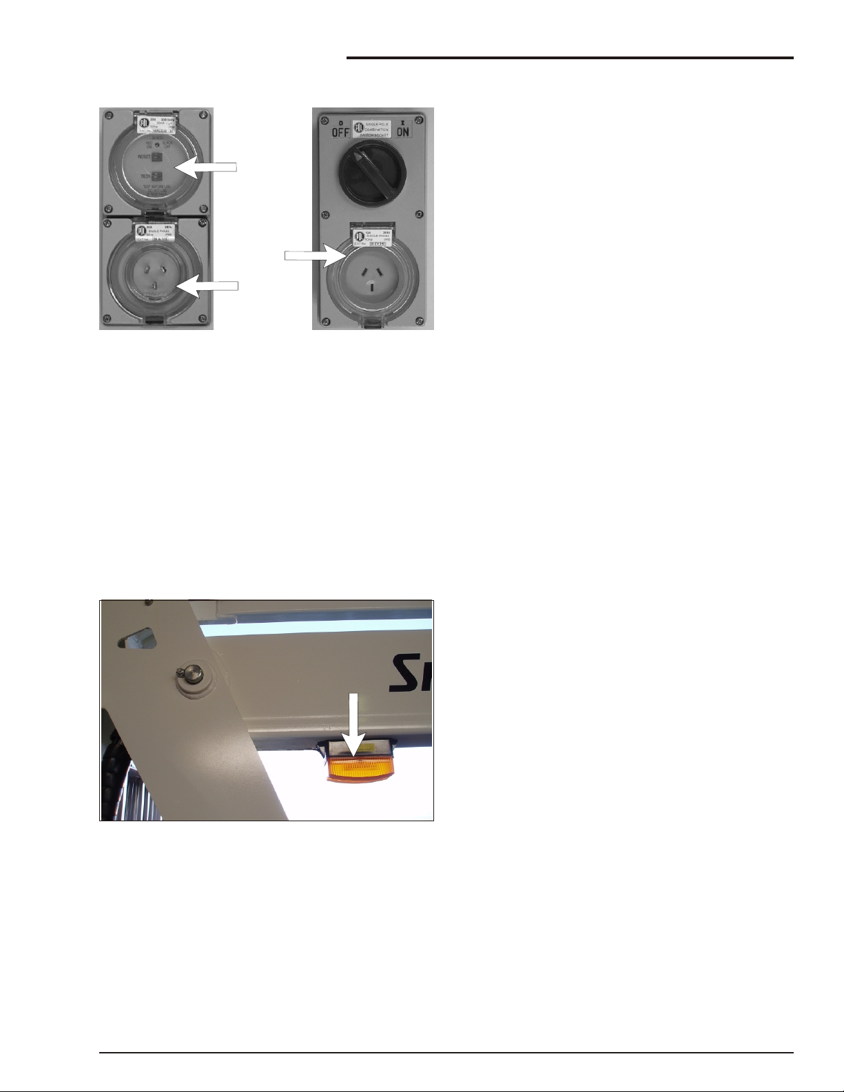
❑ RCD/ELCB AC outlet
RCD
Power Input
Connector
Power Outlet
At Platform
Figure 2.8 - RCD/ELCB AC Outlet
The RCD (Re sid ual Cur rent De vice) is lo cated at
the base and will pro tect against short cir cuits to
earth. When there is a short cir cuit the RCD will
shut down the 230v AC power to the plat form out let.
2. Safety Devices
To re set the out let dis con nect the power tool lead
from the plat form box and re set the RCD at the
base.
If the prob lem per sists call a trained ser vice tech ni cian.
❑ Flashing light
Figure 2.9 - Flashing Light
The flashing light alerts people that the MHP13/35
is moving. The light flashes at about one flash per
second any time the MASTER KEY switch is on.
There is no ON/OFF switch for the flashing light, it
cannot be turned off while the MHP13/35 is
running.
MHP13/35 – 12431A page 2 - 3
Page 19

2. Safety Devices
page 2 - 4 MHP13/35 – 12431A
Page 20

3. Specifications
The Snor kel MHP13/35 is a boom sup ported el e vat ing work plat form built to con form to these stan dards,
Amer i can Stan dard ANSI A92.2-2001, Ca na dian Stan dard C225-00 2002., Aus tra lian Stan dard
AS1418-10(Int) 2004 El e vating Work Plat forms.
NOTE:
For fur ther de tails re gard ing lu bri cants, main te nance sched ules and ser vice please re fer to the Main te nance and re pair Parts Man ual for this ma chine.
■
General Specifications
SPECIFICATIONS MHP13/35
Working height
Platform height
Rated load
Rated load (with rotator)
Platform size
Platform construction
Platform levelling
Boom type
Horizontal reach
Maximum wind speed 12.5m/s
Turntable rotation
Power source (std.)
Hydraulic system
Stabilisation
12.6m 41'
10.6m 35'
250kg 550lb
227kg 500lb
1.7 x 0.7 x 1.14m 3' 10"x 2’ 4” x 3’ 7”
Steel
Mechanical
Articulating
5.6m at 6m 19' 8" at 19' 8"
45kph 28mph
540O non-continuous or 360O continuous
Gasoline engine 5.5hp
Proportional electro/hydraulic
4 independently operated hydraulic outriggers with safety
interlocks
Stabiliser footprint (max.)
Standard colour
Transport height
Overall length
Overall width - outriggers extended
Overall width - outriggers stowed
Tyre size
Brakes
Maximum towing speed
Maximum rated axle capacity
Weight (standard model)
Insulation rating
Trailer tongue weight
MHP13/35 – 12431A page 3 - 1
3.7 x 3.6m 12' 1" x 13' 9"
Snorkel orange base and covers, white turret and booms
2.05m 6' 8"
5.99m 20' 4"
3.7m 12' 1"
1.58m 5' 2"
165 x 13LT
Hydraulic disc
80kph 50mph
1500kg 3306.9lb
1200kg 2645lb
Nil
65kg 143lb
Page 21

3. Specifications
■
Engine Data
Engine Make Honda (gas o line)
Model GX 160
Engine type 4-stroke, over head valve, 1 cylinder
Displacement 163 cm3 (9.9 cu-in)
Bore x Stroke 68 x 45 mm (2.7 x 1.8 in)
Max. output 4 kW/4,000 rpm
Max. torque 1.1 kg-m (8.0 ft-lb)/ 2500 rpm
Fuel gasoline
Fuel Grade automotive gasoline (unleaded or lowleaded preferred)
Fuel consumption 230 g/PSh
Cooling system Forced air
Ignition system Transistor magneto
PTO shaft
rotation
Oil Capacity 0.60 litres (0.60 US qt, 0.53 Imp qt)
Oil Grade SAE 10W-30
■
Recommended Hydraulic Oil
Shell Tellus 32 or Castrol AWS 32 or similar
Counterclockwise
page 3 - 2 MHP13/35 – 12431A
Page 22

1.58m
.53m
3.46m
5.99m
(6.20m Includes optional rotator)
.51m
2.05m
■
Overall Dimensions - MPH13/35
3. Specifications
MHP13/35 – 12431A page 3 - 3
Page 23

3. Specifications
13
12
11
10
9
8
7
6
5
4
3
2
1
METRES
METRES
4
3
2
1
0
4
3
2
1
5 6
7
42.6
39.3
36
32.8
29.5
26.2
22.9
19.6
16.4
13.1
9.8
6.5
3.2
FEET
FEET
13.1 9.8 6.5 3.2 0 3.2 6.5 9.8 13.1 16.4 19.6 22.9
■
Working Envelope - MHP13/35
page 3 - 4 MHP13/35 – 12431A
Page 24

Levelling
turret
Lower
boom
VIN Number
Jib
boom
Levelling
Quadrant
Upper boom
■
Jockey
wheel
Tow
coupling
Draw bar
Outriggers (4)
Trailer
Outrigger
controls
Engine
cover
Column
Ground
controls
Platform
controls
Platform
Nomenclature And Serial Numbers
❑ Right side view of machine
3. Specifications
❑ Booms identification
MHP13/35 – 12431A page 3 - 5
Page 25

3. Specifications
Oil tank
cover
Outrigger cylinder
Hand
brake
Upper
cylinder
Lower cylinder
Jib Cylinder
❑ Left side view of machine
page 3 - 6 MHP13/35 – 12431A
Page 26

4. Gauges
■
Hourmeter
Figure 4.1 - Hourmeter
The hour me ter is ba si cally an elec tric clock. It ac cu mu lates time when the mas ter key switch is
turned on. The hour me ter can not be re set. An
MHP qual i fied ser vice tech ni cian can use it to tell
when it is time for the pe ri odic main te nance listed in
the main te nance man ual.
■
Hydraulic Oil Level
Figure 4.3 - Hydraulic Oil Level
The hy drau lic oil level guage is on the side of the
hy drau lic oil tank. It shows the ac tual level of oil in side the tank. Read it only when the booms are fully
low ered and out rig gers are raised in the travel po si tion. The oil level should be within + or - 6mm (1/4”)
of the line.
■
Level Bubble
Figure 4.2 - Level Bubble
A level bub ble is lo cated in front of the out rig ger
con trols, mounted on the trailer base. Watch the
bub ble while you set the out rig gers. Lower the out rig gers, front ones first, one at a time just enough to
cen ter the bub ble in the cir cle on top of the guage.
When the bub ble is cen tral the plat form is level and
the plat form can be safely raised.
MHP13/35 – 12431A page 4 - 1
Page 27

4. Gauges
page 4 - 2 MHP13/35 – 12431A
Page 28

5. Automatic Shut-offs and Circuit Breakers
■
RCD/ELCB Outlet (option)
Figure 5.1 - RED/ELCB Outlet
The RCD (Re sid ual Cur rent De vice) is lo cated at
the base and will pro tect against short cir cuits to
earth. When there is a short cir cuit the RCD will
shut down the 230v AC power to the plat form out let.
To re set the out let dis con nect the power tool lead
from the plat form box and re set the RCD at the
base.
■
Outriggers
Figure 5.3 - Outriggers
The MHP13/35 booms can not be raised un less the
out rig gers are set and the lift en able light on the
lower con trol box is lit. Once the booms are raised
from the stowed po si tion the out rig gers be come dis abled un til the booms are stowed in the travel po si tion.
If the prob lem per sists call a trained ser vice tech ni cian.
■
Main Circuit Breaker
Figure 5.2 - Main Circuit Breaker
There is only one cir cuit breaker, on a stan dard
MHP13/35, that is ac ces si ble to the op er a tor. Its
pur pose is to pro tect the elec tri cal cir cuits from
elec tri cal over loads. When the cir cuit breaker trips
(pops out) push it back in then at tempt to use the
MHP13/35. If the cir cuit breaker trips a sec ond
time, take the MHP13/35 out of ser vice and re fer
the prob lem to a qual i fied trained ser vice tech ni cian for re pair.
MHP13/35 – 12431A page 5 - 1
Page 29

5. Automatic Shut-offs and Circuit Breakers
page 5 - 2 MHP13/35 – 12431A
Page 30

■
Platform Controls
Ground Controls
Stabiliser Controls
12385-10
LIFT
ENABLE
JIB
BOOM
UPPER
BOOM
LOWER
BOOM
ROTATE
PLATFORM
SLEW
SPEED CONTROL
EMERGENCY LOWER
1.
2.
TO LOWER PLATFORM, OPERATE
EMERGENCY LOWER SWITCH.
TO SLEW BOOM, OPERATE
‘EMERGENCY LOWER’ & ‘SLEW’
SWITCHES TOGETHER.
CHOKE
12385-11
EMERGENCY
LOWER
Optional Automatic Stabiliser Controls
12448
OUTRIGGER INTERLOCKS
OUTRIGGERS DISABLED UNLESS
BOOMS STOWED
ENSURE ALL FOUR FOOT PLATES ARE IN
FULL CONTACT WITH THE GROUND AND
THAT THEY ARE CLEAR OF MANHOLE
COVERS, DRAINS AND UNSTABLE
GROUND ETC.
2
1
4
3
CAUTION
1 2 3 4
SPEED CONTROL
BOOMS
STABILISER
CHOKE
PLATFORM
BASE
LIFT
ENABLE
HEIGHT
LOCKOUT
ONOFF
SLEW
LOWER
BOOM
UPPER
BOOM
JIB
BOOM
12523
12404-13
LF
LR
RR
RF
Auto Stow
Auto Level Manual Operation Switches
12404-12
OUTRIGGERS DISABLED UNLESS
BOOMS STOWED
OUTRIGGER INTERLOCKS
BOOMS DISABLED UNLESS ALL
OUTRIGGERS ARE DEPLOYED
AND ALL LEG INDICATOR LIGHTS
ARE LIT
CAUTION
ENSURE ALL FOUR FOOT PLATES ARE IN
FULL CONTACT WITH THE GROUND AND
THAT THEY ARE CLEAR OF MANHOLE
COVERS, DRAINS AND UNSTABLE
GROUND ETC.
LIFT ENABLE
1.
2.
RF
LF
RR
LR
DANGER
Controls Description
This chap ter ex plains what each con trol does.
This chapter DOES NOT explain how to use the
controls to produce useful work, re fer to the “Op er a tion” chap ter 8-1 for that af ter you have read this
chap ter.
For op tional equip ment con trols, see the “Op tions”
chap ter.11-1
See the “Emer gency Op er a tion” chap ter 9-1 for the
lo ca tion of the emer gency bleed down con trol and
for cor rect emer gency bleed down pro ce dures.
❑ Controls and Control Decals Locations
6. Controls
The main op er at ing func tions of an MHP13/35 can
be con trolled from the ground con trol box or from
the plat form con trol box.
Pinch points may exist between moving
components. Death or serious injury can
result from becoming trapped between
components, buildings, structures, or other
obstacles. Make sure all personnel stand
clear while operating the MHP.
MHP13/35 – 12431A page 6 - 1
Page 31

6. Controls
■
Ground Control Box
Con trols for op er at ing the MHP13/35 from the
ground, (lower con trols) are lo cated on the right
side of the turn ta ble.
❑ Lower controls:
❍
Emergency stop switch
❍
Platform/ground selector switch
❍
Choke
❍
Master key switch
❍
Boom speed switch
❍
Stabiliser/boom selector switch
❍
Lower boom switch
❍
Upper boom switch
❍
Jib boom switch
❍
Slew switch
❍
Lift enable indicator
1.
Emer gency Stop: Press the red
EMERGENCY STOP but ton in, at any time,
un der any con di tions, and the en tire ma chine
stops, and noth ing moves. This switch must
be out (on) for any thing on the MHP to work.
Pull the switch and it will pop out (on).
2.
Platform/Ground Selector : Must be in the
GROUND position (down) for the ground
control box to work. The switch MUST be in
the PLATFORM position (up) for the platform
control box to work.
3.
Choke/Cold Start: Hold the switch UP while
you start an engine that is at ambient air
temperature (a "cold" engine). This will choke
the engine.
4.
Master Key Switch: This switch works like
an automobile ignition switch. Hold it at
START until the engine starts, then release it
to ON. (-) Turn the Master Key Switch to
OFF (O) if the platform is to stay in one
position for a long time, that will turn the
engine off and save fuel.
5.
Boom Speed: This control determines how
fast the booms move. Set it to SLOW (turtle)
until you are very familiar with the way the
machine works or if the platform is working in
dangerous or cramped surroundings.
6.
Stablizer / Boom Selector Switch:
Must be in Stablizer (outrigger) position
(down) for the outriggers to work. Once
outriggers are down and set the switch must
be placed in the boom (up) position for the
booms to work.
Con trol switches 7 through 10 are the plat form
mov ing switches. Each is a three po si tion, mo men tary con tact, nor mally OFF switch.
7.
Lower Boom : UP raises the lower boom.
DOWN lowers the lower boom.
8.
Upper Boom: UP raises the upper boom.
DOWN lowers the upper boom.
9.
Jib Boom: UP raises the jib boom. DOWN
lowers the jib boom.
10.
Slew: LEFT rotates the entire turntable and
boom to the left. RIGHT rotates the entire
turntable and boom to the right.
11.
Lift Enable: The platform can only be raised
when this light is lit. When this light is not lit
the platform will not raise because the
outriggers are not properly set.
❑ Ground Control Box Controls
Lower Control Box Controls
page 6 - 2 MHP13/35 – 12431A
Page 32

6. Controls
■
Platform Control Box
Con trols for op er at ing the MHP13/35 from the plat form (up per con trols) are lo cated on the plat form
con trol box, with the ex cep tion of the foot switch
which is on the plat form floor.
❑ Upper controls:
❍
Emergency stop switch
❍
Choke
❍
Start switch
❍
Boom speed switch
❍
Emergency lower switch
❍
Platform rotate switch
❍
Lower boom switch
❍
Upper boom switch
❍
Jib boom switch
❍
Slew switch
❍
Lift enable indicator
❍
Foot switch
1.
Emergency Stop: Press the red
EMERGENCY STOP button in, at any time,
under any conditions, and the entire machine
stops, and nothing moves. This switch must
be out (on) to start or run the MHP from the
platform control box. Pull the switch and it
will pop out (on). Press the switch in (off) if
the platform is to stay in one position for a
long time. That will turn the engine off and
and save fuel.
2.
Choke/Cold Start: Hold the switch UP while
you start an engine that is at ambient air
temperature (a "cold" engine). This will choke
the engine.
3.
Start: This switch works like an automobile
ignition switch. Hold it at START until the
engine starts, then release it to ON (-). If the
engine dies in ON, the key must be turned to
OFF (O) before it will go back to START.
Turn the switch to OFF if the platform is to
stay in one position for a long time, that will
turn the engine off and save fuel.
4.
Boom Speed: This control determines how
fast the booms move. Set it to SLOW (turtle)
until you are very familiar with the way the
machine works or if the platform is working in
dangerous or cramped surroundings.
5.
Emergency Lower: If the engine stops and
cannot be restarted, hold the switch down
and this will lower the upper and lower
booms (not the jib boom). To slew during
emergency lower operate emergency lower
and slew switches together.
Items 6 through 10 are the plat form mov ing
switches. Each is a three po si tion, mo men tary con tact, nor mally OFF switch.
6.
Platform Rotate: (Option) LEFT rotates the
platform left. RIGHT rotates the platform
right.
7.
Lower Boom: UP raises the lower boom.
DOWN lowers the lower boom.
8.
Upper Boom: UP raises the upper boom.
DOWN lowers the upper boom.
9.
Jib Boom: UP raises the jib boom. DOWN
lowers the jib boom.
10.
Slew: LEFT rotates the entire turntable and
boom to the left. RIGHT rotates the entire
turntable and boom to the right.
11
Lift Enable: The platform can only be raised
when this light is lit. When this light is not lit
the platform will not raise because the
outriggers are not properly set.
Upper Control Box Controls
12.
Foot Switch: You must step down on the
foot switch, and hold it down when you use
any platform control that causes the platform
to move.
Upper Controls Foot Switch
MHP13/35 – 12431A page 6 - 3
Page 33

6. Controls
■
Stabiliser Controls
Stabiliser Controls
1.
Boom / Stabiliser Switch: Ensure the
boom/stabiliser switch on the lower control
box is set to stabiliser (see Item 6 on page 2
of this chapter)
4.
Lift Enable Light: This is a duplicate of the
lift enable light on the lower control box. The
platform can only be raised when this light is
lit. When this light is not lit the platform will
not raise because the stabilisers are not set
properly.
NOTE:
En sure that the front sta bi lis ers are low ered first
to pre vent dam age to the jockey wheel.
Ac ti vate the rear sta bi lis ers and level the ma chine us ing the level bub ble ad ja cent to the con trol levers.
NOTE:
En sure that the front sta bi lis ers are low ered first
to pre vent dam age to the jockey wheel.
2.
Valve Levers: Operate the valve levers to
activate the stabilisers and level the
machine.
3.
Bubble level: Use the bubble level to level
the machine.
■
Self Levelling Stabilisers (Option)
Self levelling Stabiliser Controls
1.
Auto Level / Stow Switch: Se lect ei ther
auto level or auto stow, to raise or lower the
sta bi lis ers au to mat i cally.
2.
Manual Stabiliser Switches: Operate the
manual switches to manually raise or lower
individual stabilisers.
3.
Leg Indicator Lights: Illuminate when the
legs are in contact with the ground.
page 6 - 4 MHP13/35 – 12431A
Page 34

7. Daily Inspection and Maintenance
WARNING
At the start of each work day (or 8 hour shift), an
MHP13/35 qual i fied op er a tor must per form the
Daily In spec tion and Main te nance as listed in the
ta ble be low.
The pur pose of the Daily In spec tion and Main te nance is to keep the MHP13/35 in proper work ing
con di tion and to de tect signs of mal func tion at the
ear li est pos si ble time.
The MHP13/35 should be in the STOWED
POSITION and the Mas ter Key Switch set to OFF
be fore you be gin this in spec tion.
■
Daily Inspection and Maintenance Table
Item Service Required
Engine fuel level Look to see that the fuel tank is full
Fuel tank cap Check to see that the cap is tight
Engine oil level Check oil level (between dipstick lines)
Fuel leaks Visually inspect (hoses and connections)
Operator's manual Check that it is in the holder on the machine
Wiring harnesses Visually inspect (installation, condition)
Battery terminals Visually inspect (no corrosion)
Battery fluid level Check fluid level (1/4" or 6 mm below filler neck)
Hydraulic oil level Visually inspect level (between lines on gauge)
Hydraulic oil leaks Visually inspect (hoses, tubes)
Tires and wheels Visually inspect (condition)
Bolts and fasteners Visually inspect (condition)
Structural damage and welds Visually inspect (weld cracks, dents)
Lanyard anchor points Visually inspect (condition)
Platform gravity gate Check condition and operation
Platform guardrails Visually inspect (condition)
Flashing light (option) Visually inspect (operation)
Ground control switches Actuate and inspect for proper operation
Level sensor (option) Check operation
Emergency lower Check operation (causes correct motion)
Platform control box switches Actuate and inspect for proper operation
RCD/ELCB AC outlet (option) Check operation
Platform work lights (option) Check operation
Placards and decals Visually inspect (installation, condition)
De fec tive parts and/or equip ment mal func tions
jeop ar dize the safety of the op er a tor and other per son nel, and can cause dam age to the ma chine.
The potential for an accident increases when
operating an MHP that is damaged or
malfunctioning. Death or serious injury can
result from such accidents. Do not operate
an MHP that is damaged or malfunctioning.
MHP13/35 – 12431A page 7 - 1
Page 35

7. Daily Inspection and Maintenance
COMBINED OIL FILLER
CAP AND DIPSTICK
OIL LEVEL FILLED TO
TOP OF FILLER NECK
OIL LEVEL
CAUTION
The rest of this chap ter shows how to per form the in spec tion and main te nance re quired for each item in
the Daily In spec tion and Main te nance Ta ble.
■
Engine Fuel Level
Figure 7.1 - Engine Fuel Level
Vi sually check to see that the gas o line tank is full.
See the “Spec i fi ca tions” chap ter 3, fuel for oc tane
and grade.
■
Engine Oil Level
Figure 7.4 - Engine Oil Level
Re move the oil filler cap and wipe the dip stick
clean. In sert the dip stick into the oil filler neck, but
do not screw it in. If the level is low, fill to the top of
the oil filler neck with the rec om mended oil.
■
Operator's Manual
The handling and use of gasoline presents
serious risk of fire and explosion if due care
is not exercised. Refer to the refueling
instructions in the safety chapter.
■
Fuel Tank Cap
Figure 7.2 - Fuel Tank Cap
Check to see that the tank cap is in place and is
tight.
Figure 7.5 - Operator Manual
Check that the Op er a tor's man ual is com plete and
in the holder on the plat form.
■
Wiring Harnesses
■
Fuel Leaks
Visually inspect the Honda fuel tank and the engine
compartment for any signs of leaking/spilt fuel.
Figure 7.6 - Wiring Harnesses
In spect all the wir ing har nesses, on the ma chine,
for loose con nec tions, bro ken wires, and frayed in su la tion.
page 7 - 2 MHP13/35 – 12431A
Page 36

■
WARNING
DANGER
Battery Terminals
Figure 7.7 - Battery Terminals
Bat tery ter mi nals should be tight, clean and free of
dirt and cor ro sion.
■
Battery Fluid Level
7. Daily Inspection and Maintenance
Figure 7.9 - Hydraulic Oil Level
The hy drau lic oil level should be be tween the two
marks on the de cal.
Batteries emit hydrogen and oxygen,
elements that can combine explosively.
Death or serious injury can result from a
chemical explosion.
DO NOT smoke or permit open flames or
sparks when checking batteries.
Figure 7.8 - Battery Fluid Level
Re move the caps from the bat tery and vi su ally
check to see that the bat tery fluid is 1/4” (6 mm) be low the bot tom of the filler neck in side each hole.
Figure 7.10 - Hydraulic Oil Filler Cap
If nec es sary, add hy drau lic oil at the filler cap. See
the “Spec i fi ca tions” chap ter 3, for type and grade of
hy drau lic oil.
■
Hydraulic Oil Leaks
Hydraulic fluid escaping under pressure can
have enough force to inject fluid into the
flesh. Serious infection or reaction can
result if medical treatment is not given
immediately. In case of injury by escaping
hydraulic fluid, seek medical attention at
once.
■
Hydraulic Oil Level
To check the hy drau lic oil level:
Com pletely lower the booms and en sure the sta bi lis ers are in the stowed position.
Figure 7.11 - Hydraulic Oil Leaks
MHP13/35 – 12431A page 7 - 3
Page 37

7. Daily Inspection and Maintenance
Mudguard
Do not search for leaks with your hand use a piece
of card board or wood.
Hy drau lic oil leaks are eas ily vis i ble and can show
up any place. Vi sually in spect the en tire ma chine
for hy drau lic oil. Check the ground un der the ma chine for leaked oil.
Care fully in spect the ends of the up per and lower
booms. Oil can run down in side of the booms and
drip out the end.
Have a qual i fied trained main te nance per son re pair all hy drau lic fluid leaks be fore you op er ate an
MHP13/35
■
Bolts and Fasteners
Vi sually in spect all fas ten ers to see that none is
miss ing or ob vi ously loose.
Figure 7.12 - Critical Pin Retainer Bolts
Crit i cal pin re tainer bolts have lock tab wash ers fit ted, they should all be pres ent and not dam aged in
any way.
Figure 7.14 - Tyre Condition
Check each wheel for ob vi ous dam age that could
cause a blow out.
Figure 7.15 - Location of Tyre Pressure Decal
En sure tyre pres sures are main tained ac cord ing to
the de cal at tached to the chas sis be hind the mud guard (fender).
■
Structural Damage and Welds
Vi sually in spect all welds for cracks, all struc tural
mem bers for de for mity.
Figure 7.13 - Wheel Nuts
Pay par tic u lar at ten tion to all of the wheel nuts and
bolts. None should be vis i bly loose, miss ing, or de formed.
■
Wheels and Tyres
The MHP13/35 re lies on it’s tyres for tow ing sta bil ity.
page 7 - 4 MHP13/35 – 12431A
Pay par tic u lar at ten tion to the chas sis welds
Figure 7.16 - Chassis Welds
Page 38

Figures 7.17 - Boom Welds
Closely in spect boom welds all the way around, for
cracks.
■
Lanyard Anchor Points
7. Daily Inspection and Maintenance
Check that the grav ity gate op er ates smoothly and
does not jam.
■
Platform Guardrails
Figure 7.18 - Lanyard Anchor Points
Vi sually check the lan yard an chor points to see that
they are not de formed or cut off.
■
Platform Gravity Gate
Figure 7.20 - Platform Guardrails
Vi sually in spect the plat form guard rails to see that
none of the tub ing has been cut out, re moved, or
de formed in any way.
Vi sually check the guard rail welds to see that none
is cracked nor ground down.
■
Flashing Light (option)
Figure 7.21 - Flashing Light
Vi sually check the op tional flash ing light, to see
that the light flashes at ap prox i mately one flash per
sec ond when the mo tor key switch is turned on.
Figure 7.19 - Platform Gravity Gate
MHP13/35 – 12431A page 7 - 5
Page 39

7. Daily Inspection and Maintenance
■
Ground Control Switches
Figure 7.22 - Ground Control Switches
With the Ground/Platform Selector set to
ground:
Check that each of the platform moving switches
( through to ) cause the MHP13/35 to move the
way it should.
Check both po si tions of each switch.
For cor rect op er at ing pro ce dures see the “Op er a tion” chap ter 8.
NOTE
Pay particular attention to the Emergency Stop
switch to see that it turns the MHP13/35
engine off when the red button is struck.
With the booms raised open the Emergency
Lower Valve at the rear of the column.
The booms should be gin to lower. The rate of low er ing can be reg u lated by the amount the valve is
opened.
To check the slew func tion when us ing the man ual
emer gency lower valve the Mas ter Key Switch
and Emer gency Stop switch must be on and the
Plat form/ground Se lec tor must be set to ground.
To slew (with the man ual emer gency lower valve
al ready open) se lect the re quired di rec tion on the
slew tog gle switch .
NOTE
The manual emergency lower valve must be
closed after the test to ensure proper boom
operation.
For cor rect emer gency low er ing op er at ing pro ce dures see “Emer gency Op er a tion” chap ter 9.
❑ Upper control box
Emer gency lower from the up per con trol box is
achieved by turn ing the up per con trol to on and de press ing the foot switch whilst op er at ing the Emer -
gency Lower switch
To slew the unit se lect the di rec tion re quired on the
slew tog gle switch at the same time. For cor rect
emer gency low er ing op er at ing pro ce dures see
“Emer gency Op er a tion” chap ter 9.
■
Platform Control Switches
■
Emergency Lower
❑ Lower control box
Figure 7.24 - Platform Control Switches
On the ground con trol box set the Ground/Plat form Se lec tor to plat form.
Check that each of the platform moving switches
( through to ) cause the platform to move the
Figure 7.23 - Emergency Lower Valve
page 7 - 6 MHP13/35 – 12431A
way it should.
Page 40

Check both po si tions of each switch.
CAUTION
7. Daily Inspection and Maintenance
For cor rect op er at ing pro ce dures see the ”Op er a tion” chap ter 8.
NOTE
Pay particular attention to the Emergency Stop
switch to see that it turns the MHP13/35
engine off when struck.
Pay particular attention to the platform foot switch
to see that it deactivates the platform moving
switches when the foot switch is not stepped on.
■
AC Outlet RCD/ELCB (option)
No Part No Description Req
9972-MHP Serial number plate
1
451776 Decal - Hydraulic fluid level
2
9751 Decal - NZ made
3
302950 Decal - Hydraulic oil level
4
12424 Decal - Towing speed
6
9207 Decal - Hydraulic oil
7
9428
8
1843
569295 Decal - Snorkel
9
562426 Decal - Operation manual
10
0083426 Decal - Tie down
11
12447 Decal - MHP13/35
12
9213 Decal - Petrol
13
300699 Decal - Operator checklist
14
0130025 Decal - Warning
15
Decal - Danger (Australia only)
Decal - Warning (NZ only)
1
1
1
1
1
1
1
1
2
1
4
2
1
1
1
Figure 7.25 - AC Outlet RCD/ELCB
If the MHP13/35 has this op tion fit ted check the
RCD works by con nect ing a power source to the
base in let and an ap pli ance to the plat form out let.
Push the test but ton on the RCD/ELCB de vice and
the power out let at the plat form should not work.
RCD/ELCB devices should only be serviced
or replaced by a qualified electrician.
■
Placards and Decals
Look to see that all plac ards and de cals are in place
and leg i ble. Re place any miss ing or il leg i ble plac ards or de cals be fore plac ing the MHP into ser vice
for the daily work shift.
De cal and plac ard kits for the MHP13/35 are avail able from Snor kel deal ers.
0323897 Decal - Danger
16
476706 Decal - Danger explosive gas
17
11420 Decal - Lower control box
18
0323899 Decal - Electrocution hazard
19
0150602 Decal - Descending boom
20
451986 Decal - Limit switches
21
9223-3 Decal - Chevron
22
12448 Decal - Outrigger control
23
8945 Decal - Vin plate
24
7856-45 Decal - Tyre pressure
25
12423-250 Decal - Safe working load
26
12423-227 Decal - Safe working load
12423-227 Decal - Safe working load
12423-200 Decal - Safe working load
(NZ/Aust Units without rotator)
(NZ/Aust Units with rotator
(US/CE Units without rotator)
(US/CE Units with rotator
1
1
1
2
4
6
8
1
1
2
1
1
1
1
99228-1 Decal - Caution
❑ Standard placards and decals
See page 7 - 8 for the fol low ing items.
MHP13/35 – 12431A page 7 - 7
27
1772-002K Decal - Boom lock pin
28
0072531 Decal - Electrocution hazard
29
0150448 Decal - Lanyard
30
12517 Decal - Auto stabiliser operation
31
1
2
1
1
1
Page 41

7. Daily Inspection and Maintenance
7
4
2
19
12
15
15
1
31
28
9
13
17
21
25
29
18
23
12
14
20
24
25
19
20
20
20
6
9
22
x 8
28
21
x 4
11
x 4
16
19
10
30
3
26
8
27
❑ Inspection drawing
page 7 - 8 MHP13/35 – 12431A
Page 42

■
CAUTION
DANGER
Operating Procedures
This chap ter ex plains how to prop erly start and op er ate an MHP13/35. Read and un der stand all the
pre vi ous chap ters in this man ual be fore you be gin
to op er ate an MHP13/35.
If you use the MHP13/35 for painting be sure
the optional sandblast protection kit is
installed to protect the hydraulic cylinder
rods from paint. Do not leave the MHP13/35
engine running if you are sandblasting.
Sand drawn into the air intake can erode
engine parts.
■
Control Stations
An MHP13/35 can be op er ated from the ground
con trol box or from the plat form con trol box. There
are ba si cally two dif fer ences be tween ground con trol and plat form con trol op er a tions, both are safety
re lated:
1. The ground control box can override the
platform control box at any time. If a person
operating the machine from the platform
becomes incapacitated, a person on the
ground can always take over machine control.
2. The outriggers can only be selected from the
ground control box and only when the
booms are in the stowed position.
8. Operation
Figure 8.1 - Ground Con trol Box Emer gency
Stop Switch Lo ca tion.
■
Emergency Stopping
Upper Control Box
To stop an MHP13/35 from the upper control box
push the Emergency Stop switch in (see Figure
8.2).
The MHP13/35 is not Electrically Insulated.
Death or Serious Injury to operating
personnel, can occur if the machine should
come into contact with energized electrical
wires during operation.
DO NOT attempt to operate the MHP13/35
ground controls if the platform, booms, or
any other conducting part of an MHP13/35 is
in contact with energized electrical wires or
if there is an immediate danger of such
contact.
NOTE
See the "Electrical Hazard" section, in this
manual for a complete explanation of the hazards
concerning electricity.
■
Emergency Stopping
Lower Control Box
To stop an MHP13/35, from the lower control box
push the Emergency Stop switch in (see Figure
8.1).
Figure 8.2 - Platform Control Box Emergency
Stop Switch Location.
NOTE
For a complete discussion of the Emergency
Stop switches, see “Controls” chapter 6, in this
manual.
MHP13/35 – 12431A page 8 - 1
Page 43

8. Operation
CAUTION
WARNING
■
Operation Considerations
To use this chap ter, first de cide whether you will be
start ing and op er at ing the MHP13/35 from the
ground con trol box or the plat form con trol box.
Be gin at the sec tion en ti tled "Starting From Ground
Con trol Box", if you in tend to start and run the
MHP13/35 from the ground sta tion.
Be gin at the sec tion en ti tled "Starting From Plat form Con trol Box", if you in tend to start and run the
MHP13/35 from the plat form.
■
Starting From Ground Control Box
Be fore you be gin to op er ate the MHP13/35 from
the ground con trol box, a qual i fied op er a tor must
per form the "Daily In spec tion and Main te nance" as
de scribed in chap ter 7, of this man ual.
To start the en gine from the ground con trol box do
the fol low ing:
1.
Set the Emergency Stop switch to ON
(see Figure 8.3).
5.
Turn the key to Start and hold it there un til
the en gine starts or for a max i mum time of 6
sec onds. When the en gine starts re lease the
key and the choke switch , if you used it
(see Figure 8.3).
If the engine does not start in 6 seconds turn
the key off and release the choke. Wait 60
seconds before trying to restart the engine
again. Continual cranking of the starter
motor will only result in its damage.
The en gine should now be run ning, and the
MHP13/35 is ready to be gin work.
■
Stabiliser Operation
NOTE:
The sta bi lis ers will only func tion when the booms
are stowed. Once the booms are raised the sta bi lis ers will not op er ate.
En sure the boom/sta bi liser switch (item on the
ground con trol box) (see Fig ure 8.3) is set to sta bi liser.
Figure 8.3 - Ground Control Box Starting
2.
Set the Platform/Ground Selector switch
to GROUND (see Figure 8.3).
3.
Insert the key (see Figure 8.3) into the
Master Key Switch and turn the key on.
4. If the engine is at ambient temperature
(cold), hold the Choke / Cold Start Switch
(see Figure 8.3) up throughout the next
step.
Ac ti vate the sta bi lis ers with the valve le vers en sur ing that the front sta bi lis ers are low ered first to pre vent dam age to the jockey wheel.
Ac ti vate the rear sta bi lis ers and level the ma chine
us ing the level bub ble ad ja cent to the con trol le vers.
When levelling the machine in either the
manual or automatic mode care is required
to ensure that all of the foot plates are firmly
on the ground, the machine is level and the
lift enable light (item Fig 8.3, and item Fig
8.4) is ON before entering the platform.
■
Self Levelling Stabilisers (Option)
Figure 8.4 - Auto Level Controls
page 8 - 2 MHP13/35 – 12431A
Page 44

For units fit ted with self lev el ling sta bi lis ers the fol -
WARNING
low ing ap plies.
1. Press and hold down the auto level switch
.
The sta bi lis ers will lower and the ma chine will
“level” au to mat i cally.
NOTE:
Switch is also used to raise the sta bi lis ers to
the stowed po si tion. To do so press and hold
switch in the auto stow di rec tion and all the
sta bi lis ers will raise au to mat i cally to the stowed
po si tion.
NOTE:
Although this option is designed to automatically
set the sta bi lis ers it is also possible to set the
sta bi lis ers manually.
❑ Setting the stabilisers manually
1.
Operate each switch (see Figure 8.4) to
raise or lower each stabiliser one at a time.
Use the level bubble (see Figure 2.7 in
Safety Devices Chapter) to check the
machine is level.
8. Operation
Figure 8.5
2.
Set the Platform/Ground Selector (see
Figure 8.5) at the ground control box to
PLATFORM.
When levelling the machine in either the
manual or automatic mode care is required
to ensure that all of the foot plates are firmly
on the ground, the machine is level and the
lift enable light is ON before entering the
platform.
■
Starting From Platform Control Box
Be fore you be gin to op er ate the MHP13/35 from
the plat form con trol box, a qual i fied op er a tor must
per form the "Daily In spec tion and Main te nance" as
de scribed in chap ter 7, of this man ual.
To start the en gine from the plat form con trol box
you must first set some switches on the ground
con trol box, in clud ing set ting the out rig gers and
lev el ing the ma chine.
(See page 8-2 for in for ma tion on set ting the sta bi lis ers)
1.
Insert the key into the Master Key Switch
at the ground control box and turn the key on
(see Figure 8.5).
Figure 8.6
3.
Enter the platform, close the gravity gate ,
and attach the lanyard of your fall restraint
(safety harness) to one of the anchor points
(see Figure 8.6).
MHP13/35 – 12431A page 8 - 3
Page 45

8. Operation
DANGER
CAUTION
WARNING
Figure 8.7
4.
Set the Emergency Stop switch to (ON)
(see Figure 8.7).
5.
Turn the Start switch to ON (see Figure
8.7).
6. If the engine is at ambient temperature (cold),
hold the Choke Switch (see Figure 8.7) up
throughout the next step.
7.
Turn the Start switch to START and hold
it there until the engine starts or for a
maximum time of 6 seconds. When the
engine starts, release the key (6) and the
choke switch , if you used it (see Figure
8.7).
Be certain that the space into which you are
about to move the platform, boom, turntable,
and/or chassis is free of obstructions.
ALWAYS look in the direction of movement.
When you operate from the platform control
box, be sure that the lanyard of your fall
restraint is attached to an anchor point on
the platform mount. Also, be sure that
platform gate is closed behind you.
❑ From Ground Control Box
Each of the ways the plat form can move is shown in
the fol low ing pho to graph and switch il lus tra tion:
The pho to graph shows the plat form switches that
cause the plat form or booms to move.
These plat form mov ing switches, ( through ),
will pro duce the move ment as in di cated by the il lus tra tion's to the right.
If the engine does not start in 6 seconds, turn
the Start switch OFF.and release the choke.
Wait 60 seconds before trying to restart the
engine again. Continual cranking of the
starter motor will only result in its damage.
The en gine should now be run ning, and the
MHP13/35 is ready to be gin work.
■
Moving The Platform
The en gine should al ready be run ning (as de scribed ear lier in this chap ter), be fore you start this
sec tion.
DO NOT operate near energized electrical
conductors. Maintain the (M.S.A.D.),
Minimum Safe Approach Distance to
energized power lines. See the "Electrical
Hazard" section, in this manual for a
complete explanation of the hazards
concerning electricity. Maintain the
clearances shown on the decal attached to
the platform.
Figure 8.8 - Movement Control, Ground
Control Box
page 8 - 4 MHP13/35 – 12431A
Page 46

8. Operation
❑ From Platform Control Box
When you op er ate from the plat form con trol box, be
sure that the lan yard of your fall re straint is at tached to an an chor point on the plat form mount.
Also, be sure the grav ity gate is closed. Each of the
ways the plat form can move is shown in the fol low ing pho to graph and switch il lus tra tion:
The pho to graph shows the plat form switches that
cause the plat form or booms to move.
These plat form mov ing switches, ( through ),
will pro duce the move ment as in di cated by the il lus tra tion's to the right.
■
Securing for Day
At the end of each work day the MHP13/35 should
be re turned to the STOWED POSITION and locked
as de scribed un der “Stowing” in the "Stowing and
Trans porting" chap ter 10.
Figure 8.10 - Movement Control, Platform
Control Box
You must be step ping on the plat form foot switch
when you use any of the plat form mov ing
switches ( through ) The plat form foot switch is
a safety fea ture to pre vent the plat form from mov ing if a plat form mov ing switch, or con trol ler, is ac ci den tally pushed.
Figure 8.11 - Platform Foot Switch
MHP13/35 – 12431A page 8 - 5
Page 47

■
Emergency Operation Procedures
The fol low ing pro ce dures are emer gency pro ce dures only. DO NOT use them for nor mal op er a tion. Their pur pose is to get the plat form and
op er a tor safely to ground when the MHP13/35 will
not start or some other prob lem keeps the plat form
from low er ing in the nor mal way.
❑ Operation From Platform Control Box
Switch set tings listed in the three steps be low must
ex ist at the ground be fore emer gency op er a tion
pro ce dures will work at the plat form con trol box:
9. Emergency Operation
Figure 9.3
6.
Step on the platform foot switch (see
Figure 9.3).
Figure 9.1
1.
The Master Key Switch must be ON (see
Figure 9.1).
2.
The Emergency Stop switch must be
(ON) (see Figure 9.1).
3.
The Platform/Ground Selector switch
(see Figure 9.1) must be set to PLATFORM.
Figure 9.2
4.
Set the Emergency Stop switch to ON
(see Figure 9.2).
5.
Set the Start switch (see Figure 9.2) to
ON.
Figure 9.4
7.
Hold the Emergency Lower switch (see
Figure 9.4) down and the platform will begin
lowering.
8. To lower the jib boom, operate the
Emergency Lower switch and the Jib
Boom Lower switches together (see
Figure 9.4).
9.
To slew the boom, operate the Emergency
Lower and Slew switches together
(see Figure 9.4).
NOTE:
When emer gency low er ing, it is only pos si ble to
Slew or lower the Jib Boom whilst the Up per and
Lower booms are low er ing.
MHP13/35 – 12431A page 9 - 1
Page 48

9. Emergency Operation
❑ Operation From Ground Control Box
Figure 9.5 - Manual Lower Valve
1. Open man ual valve to lower the plat form by
turn ing the knob coun ter clock wise.
NOTE 1:
To slew or lower the Jib Boom when us ing the
Emer gency Low er ing valve the Mas ter Key
Switch and the Emer gency Stop Switch must
be on and the Plat form/Ground Switch must be
set to ground (see Fig ures 9.1 and 9.2).
Op er ate Slew or Jib Boom Lower at the lower
con trol box whilst the booms are low er ing.
NOTE 2:
When emer gency low er ing, it is only pos si ble to
Slew or lower the Jib Boom whilst the Up per and
Lower booms are low er ing.
NOTE 3:
When us ing the emer gency low er ing valve it is
im por tant to close the valve fully (turn the knob
clock wise) once low er ing is com plete.
page 9 - 2 MHP13/35 – 12431A
Page 49

■
DANGER
Stowing
At the end of each work day (or in prep a ra tion for
lift ing or stor age) a qual i fied op er a tor should put
the MHP13/35 into its stowed po si tion then lock by
plac ing the two boom lock pins in po si tion.
❑ The correct stowed position is shown
here.
10. Stowing and Transporting
Figure 10.3 -Upper Boom Lock Pin
Figure 10.1 - Stowed Position
To bring the MHP13/35 into the STOWED
POSITION use the con trols on the ground con trol
box or plat form con trol box to:
1. Align the lower boom with the boom rest
mounted to the drawbar.
2. Fully lower all booms.
3.
Insert lower boom pin in place (see
Figure10.2) and ensure snap pin is
correctly locked in place through the boom
pin.
If using the upper controls go now to the
ground controls and:
4.
Switch the Ground / Platform selector to
ground.
5.
Set the Booms / Stabiliser selector to
stabiliser.
6. Using the stabiliser controls raise the
stabilisers (rear first to avoid damage to the
jockey wheel)
7.
Set the Master Key switch on the ground
control box to off and remove the key.
■
Transporting
❑ Trailering
When mov ing the MHP13/35 on a trans port trailer
the fol low ing points must be ad hered to.
1.
The unit must be in the stowed position.
2.
Care must be taken when loading the unit
onto the trailer that it does not run away.
Chock the wheels and apply the
handbrake.
3.
The MHP13/35 can be loaded by forklift.
Figure 10.2 - Lower Boom Lock Pin
4.
Insert upper boom pin in place and ensure
the snap pin is correctly locked in place
through the boom pin (see Figure 10.3)
MHP13/35 – 12431A page 10 - 1
Page 50

10. Stowing and Transporting
DANGER
❑ Forklift points
Figure 10.4 - Forklift Points
❑ Securing to a Transport Vehicle
4. Tie down only using the 4 tie down points.
DO NOT
●
Tie down over the draw bar.
●
Tie down over the booms or level rods.
●
Tie down over the platform.
9. Check the covers are secure and no debris
or work tools are in the platform.
10. Check both booms are stowed correctly.
Reverse the above procedure after transporting.
■
Towing
The correct size tow ball MUST be used when
connecting the draw bar to the towing vehicle.
The coupling is stamped with the correct size.
Be aware of local transport regulations.
1. Visually inspect the tow ball on the towing
vehicle.
2. Ensure the tow ball is matching in size with
the tow coupling on the trailer.
3. Ensure the tow ball is mounted correctly and
is fitted tightly.
4. Connect the tow coupling and ensure the
latching mechanism is working and has
latched.
5. Connect the break-away chain to the towing
vehicle, unset the reversing lock on the tow
coupling.
6. Check that the bolt or D-Clamp on the
breakaway chain is able to take the rated
load.
7. Connect the trailer road lights to the towing
vehicle and test that the functions work.
8. Retract the jockey wheel and place it in the
stowed position (see photograph top right).
Death or Serious Injury can result from
losing control of a trailer when towing.
Never tow above the rated speed marked on
the draw bar.
Never tow the unit with an under rated
vehicle. Always check manufacturers
vehicle load specifications.
page 10 - 2 MHP13/35 – 12431A
Page 51

11. Options
CAUTION
■
Air Line To Platform
This con sists of *” pres sure flex yel low hose rated
at 150 psi work ing pres sure, fit ted with quick dis con nect cou plers at each end .
■
Dual Fuel
This op tion con sists of an AC mo tor rated at ei ther
110 or 230 volts AC 50/60Hz mounted un der the fi ber glass cov ers. A se lec tor switch is used to change
from gas o line to elec tric. The same con trols are
used to stop and start the elec tric mo tor.
This op tion is used in shop ping malls and other
built up ar eas.
■
24V DC Battery Power
This op tion con sists of a 24V DC mo tor and bat ter ies that are used to power all func tions.
■
Bi-Energy
This con sists of a com bi na tion of both gas o line (or
die sel) en gine and the 24V DC mo tor to give a
Bi-en ergy op tion.
■
Platform Rotator
This op tion al lows the op er a tor to move the plat form around the boom, 45o each side of cen ter, to
gain better ac cess to work sites.
■
Work Lights
Rub ber en cased work lights can be fit ted to the
plat form guard rails. The lights are swivel mounted
and each has its own switch.
■
Flashing Light
●
For this option see Chapter 2 page 3
■
RCD/ELCB AC Outlet
A 3 core wire rated at 600 volts AC 15 amps is run
up the booms as stan dard.
●
For this option see Chapter 2 Page 3.
■
Sandblast Protection Kit
This op tion con sists of a bel lows type cover fit ted to
each boom cyl in der shaft.
The bel lows pre vent sand and paint from dam ag ing
the cyl in der rods and seals, and thus pre vent hy drau lic oil leaks.
DO NOT paint or sandblast from an
MHP13/35 unless the cylinder rods are
protected by bellows.
MHP13/35 – 12431A page 11 - 1
Page 52

11. Options
page 11 - 2 MHP13/35 – 12431A
Page 53

12. Fire Fighting and Chemical Containment
DANGER
DANGER
DANGER
■
Hazardous Components
Snor kel prod ucts may con tain ma te ri als and ob jects that po ten tially could be come sig nif i cant fire
or en vi ron men tal haz ards dur ing the life time of the
ma chine.
The ma te ri als in the fol low ing list may be con tained
in the MHP13/35:
1. Antifreeze (ethylene glycol)
2. Battery, lead/acid
3. Diesel fuel
4. Foam in tires
5. Gasoline
6. Hydraulic oil
7. Liquefied petroleum gas
8. Motor oil
The rest of this chap ter lists man u fac tur ers’ in for ma tion you will need if you ever have to con trol any
of the above items dur ing an up set or emer gency.
❑ Antifreeze (UN 1993)
☞
Fire extinguishing media:
Dry Chem i cal, foam, or CO2.
☞
Special fire fighting procedures:
Use pos i tive pres sure, self con tained breath ing ap pa ra tus.
☞
Unusual fire and explosion hazards:
Hy dro gen and ox y gen gases are pro duced in the
cells dur ing nor mal bat tery op er a tion.
Hydrogen gas is flammable and oxygen
supports combustion. These gases enter
the air through the vent caps. To avoid the
chance of a fire or explosion, keep sparks
and other sources of ignition away from the
battery.
☞
Spill or leak:
Re move com bus ti ble ma te ri als and all sources of
ig ni tion. Con tain spill by diking with soda ash (so dium car bon ate) or quick lime (cal cium ox ide).
Cover spill with ei ther chem i cal. Mix well. Make
cer tain mix ture is neu tral then col lect res i due and
place in a drum or other suit able con tainer. Dis pose of as haz ard ous waste.
☞
Special fire fighting procedures:
Wa ter spray may be in ef fec tive on fire but can pro tect fire fight ers and cool closed con tain ers. Use
fog noz zles if wa ter is used.
DO NOT enter confined fire space without
full bunker gear. (Helmet with face shield,
bunker coats, gloves & rubber boots). Use a
NIOSH approved positive pressure self
contained breathing apparatus. Keep
container tightly closed. Isolate from
oxidizers, heat and open flame.
☞
Spill or leak:
Small - mop up with ab sor bent ma te rial and trans fer to hood.
☞
Waste disposal method:
Small - evap o rate un til all va pors are gone. Dis pose of re main der by le gally ap pli ca ble meth ods.
ALWAYS wear acid resistant boots, face
shield, chemical splash goggles, and acid
resistant gloves when handling acid spills or
leaks.
NOTE
DO NOT release UN-neutralized acid!
☞
Waste disposal method:
Sul fu ric Acid: Neu tral ize as above for a spill, col -
lect res i due, and place in a drum or suit able con tainer. Dis pose of as haz ard ous waste.
NOTE
DO NOT flush lead contaminated acid to sewer.
☞
Waste disposal method
Bat teries: Send to lead smelter for rec la ma tion fol -
low ing ap pli ca ble fed eral, state, and lo cal reg u la tions.
❑ Diesel Fuel (NA 1993)
❑ Battery, Lead/Acid (UN 2794)
☞
Extinguishing media:
Dry chem i cal, foam, or CO2.
MHP13/35 – 12431A page 12 - 1
☞
Extinguishing media:
Use wa ter spray, dry chem i cal, foam, or CO2.
Page 54

12. Fire Fighting and Chemical Containment
DANGER
DANGER
DANGER
☞
Special fire fighting procedures:
Use wa ter to keep fire ex posed con tain ers cool. If
leak or spill has not ig nited, use wa ter spray to dis perse the va pors and to pro vide pro tec tion for per son nel at tempt ing to stop a leak. Wa ter spray may
be used to flush spills away from ex po sures.
☞
Unusual fire and explosion hazards:
Prod ucts of com bus tion may con tain car bon mon ox ide, car bon di ox ide, and other toxic ma te ri als.
DO NOT enter enclosed or confined space
without proper protective equipment
including respiratory protection.
Burning produces intense heat, dense
smoke, and toxic gases, such as carbon
monoxide, oxides of nitrogen, and traces of
hydrogen cyanide.
☞
Spill or leak:
Pick up and han dle as any other in ert solid ma te rial.
☞
Waste disposal method:
Not con sid ered a haz ard ous ma te rial. Dis pose of
ma te rial ac cord ing to any lo cal, state, and fed eral
reg u la tions.
☞
Spill or leak:
Con tain spill im me di ately in small est area pos si ble.
Re cover as much of the prod uct it self as pos si ble
by such meth ods as vac u um ing, fol lowed by soak ing up of re sid ual flu ids by use of ab sor bent ma te ri als.
Re move con tam i nated items in clud ing con tam i nated soil and place in proper con tain ers for dis posal. Avoid wash ing, drain ing, or di rect ing
ma te rial to storm or san i tary sew ers .
☞
Waste disposal method:
Re cy cle as much of the re cov er able prod uct as
pos si ble.
Dis pose of non-recyclable ma te rial as a RCRA
haz ard ous waste by such meth ods as in cin er a tion,
com ply ing with fed eral, state, and lo cal reg u la tions.
❑ Foam In Tires
☞
Extinguishing media:
Wa ter, dry chem i cal, foam, or CO2.
❑ Gasoline (UN 1203)
☞
Extinguishing media:
Dry chem i cal, foam, or CO2.
☞
Special fire fighting procedures:
Wa ter may be in ef fec tive to ex tin guish, but wa ter
should be used to keep fire ex posed con tain ers
cool. If a leak or spill has not ig nited, use wa ter
spray to dis perse the va pors and to pro tect per son nel at tempt ing to stop a leak. Wa ter spray may be
used to flush spills away from ar eas of po ten tial ig ni tion.
☞
Unusual fire and explosion hazards:
Highly Flam ma ble. Prod ucts of com bus tion may
con tain car bon mon ox ide, car bon di ox ide and
other toxic ma te ri als.
DO NOT enter enclosed or confined space
without proper protective equipment
including respiratory protection.
☞
☞
Special fire fighting procedures:
Evac u ate non emer gency per son nel to a safe area.
☞
Unusual fire and explosion hazards:
Fire fight ers should use self con tained breath ing
ap pa ra tus. Avoid breath ing smoke, fumes, and de com po si tion prod ucts.
Use wa ter spray to drench smol der ing elas to mer.
Prod uct may melt, af ter ig ni tion, to form flam ma ble
liq uid.
page 12 - 2 MHP13/35 – 12431A
Spill or leak:
Re view fire and ex plo sion haz ards be fore pro ceed ing with clean up. Use ap pro pri ate per sonal pro tec tive equip ment dur ing clean up. Dike spill. Pre vent
liq uid from en ter ing sew ers, wa ter ways, or low ar eas.
Soak up with saw dust, sand, oil dry or other ab sor bent ma te rial. Shovel or sweep up.
Remove source of heat, sparks, flame, impact,
friction or electricity including internal combustion
engines and power tools. If equipment is used for
spill cleanup, it must be explosion proof and
suitable for flammable liquid and vapor.
Page 55

12. Fire Fighting and Chemical Containment
CAUTION
DANGER
DANGER
NOTE
Vapors released from the spill may create an
explosive atmosphere.
☞
Waste disposal method:
Treat ment, stor age, trans por ta tion and dis posal
must be in ac cor dance with ap pli ca ble fed eral,
state, pro vin cial, and lo cal reg u la tions.
DO NOT flush to surface water or sanitary
sewer system. By itself, the liquid is
expected to be a RCRA ignitable hazardous
waste.
❑ Hydraulic Oil (UN 1270)
☞
Extinguishing media:
Use wa ter spray, dry chem i cal, foam, or CO2.
☞
Special fire fighting procedures:
Wa ter or foam may cause froth ing. Use wa ter to
keep fire ex posed con tain ers cool. Wa ter spray
may be used to flush spills away from ex po sures.
☞
Unusual fire and explosion hazards:
Prod ucts of com bus tion may con tain car bon mon ox ide, car bon di ox ide, and other toxic ma te ri als.
DO NOT enter enclosed or confined space
without proper protective equipment
including respiratory protection.
☞
Spill or leak:
Con tain spill im me di ately in small est area pos si ble.
Re cover as much of the prod uct it self as pos si ble
by such meth ods as vac u um ing, fol lowed by soak ing up of re sid ual flu ids by use of ab sor bent ma te ri als.
Re move con tam i nated items in clud ing con tam i nated soil and place in proper con tain ers for dis posal. Avoid wash ing, drain ing or di rect ing ma te rial
to storm or san i tary sew ers .
Dis pose of non-recyclable ma te rial as a RCRA
haz ard ous waste by such meth ods as in cin er a tion,
com ply ing with fed eral, state, and lo cal reg u la tions.
❑ Liquefied Petroleum Gas (UN 1075)
☞
Extinguishing media:
Wa ter spray. Class A-B-C or BC fire extinguishers.
☞
Special fire fighting procedures:
Stop flow of gas. Use wa ter to keep fire ex posed
con tain ers cool. Use wa ter spray to dis perse un ig nit ed gas or va por.
If ig ni tion has oc curred and no wa ter avail able, tank
metal may weaken from over heat ing. Evac u ate
area. If gas has not ig nited, LP gas liq uid or va por
may be dis persed by wa ter spray or flood ing.
☞
Unusual fire and explosion hazards:
Highly Flam ma ble. Prod ucts of com bus tion may
con tain car bon mon ox ide, car bon di ox ide and
other toxic ma te ri als.
DO NOT enter enclosed or confined space
without proper protective equipment
including respiratory protection.
☞
Spill or leak:
Keep pub lic away. Shut off sup ply of gas. Elim i nate
sources of ig ni tion. Ven ti late the area. Dis perse
with wa ter spray.
Con tact be tween skin and these gases in liq uid
form can cause freez ing of tis sue caus ing in jury
sim i lar to ther mal burn.
NOTE
Vapors released from the spill may create an
explosive atmosphere.
☞
Waste disposal method:
Treat ment, stor age, trans por ta tion and dis posal
must be in ac cor dance with ap pli ca ble fed eral,
state, pro vin cial, and lo cal reg u la tions.
☞
Waste disposal method:
Re cy cle as much of the re cov er able prod uct as
pos si ble.
MHP13/35 – 12431A page 12 - 3
❑ Motor Oil (UN 1270)
☞
Extinguishing media:
Use wa ter spray, dry chem i cal, foam, or CO2.
Page 56

12. Fire Fighting and Chemical Containment
DANGER
☞
Special fire fighting procedures:
Wa ter or foam may cause froth ing. Use wa ter to
keep fire ex posed con tain ers cool. Wa ter spray
may be used to flush spills away from ex po sures.
☞
Unusual fire and explosion hazards:
Prod ucts of com bus tion may con tain car bon mon ox ide, car bon di ox ide, and other toxic ma te ri als.
DO NOT enter enclosed or confined space
without proper protective equipment
including respiratory protection.
☞
Spill or leak:
Con tain spill im me di ately in small est area pos si ble.
Re cover as much of the prod uct it self as pos si ble
by such meth ods as vac u um ing, fol lowed by soak ing up of re sid ual flu ids by use of ab sor bent ma te ri als.
Re move con tam i nated items in clud ing con tam i nated soil and place in proper con tain ers for dis posal. Avoid wash ing, drain ing or di rect ing ma te rial
to storm or san i tary sew ers .
☞
Waste disposal method:
Re cy cle as much of the re cov er able prod uct as
pos si ble.
Dis pose of non-recyclable ma te rial as a RCRA
haz ard ous waste by such meth ods as in cin er a tion,
com ply ing with fed eral, state, and lo cal reg u la tions.
page 12 - 4 MHP13/35 – 12431A
Page 57

■
CAUTION
Troubleshooting
All of the ac tions de scribed in this chap ter may be
per formed by an MHP13/35 op er a tor, a trained and
qual i fied ser vice tech ni cian is not re quired.
The first col umn, of the fol low ing chart, lists some
com mon prob lems en coun tered by MHP13/35 op er a tors.
The sec ond col umn lists some of the causes for
each prob lem. The third col umn lists rem e dies.
❑ Operator Troubleshooting Chart
Problem Cause Remedy
13. Operator's Troubleshooting
Any problem that cannot be fixed by actions
listed below should be referred to a trained
and qualified MHP13/35 service technician.
Engine will not crank.
Engine cranks but will
not start.
Engine runs but no
outrigger function.
Engine runs but no
boom function.
1. Flat battery. Replace / charge battery.
2. Main circuit breaker, in
ground control box, has
tripped..
3. Loose battery terminals . Tighten battery leads at battery.
1. Out of fuel. Fill the engine with the correct type / grade of
2. Fuel tap off. Locate fuel tap on engine and turn to ON.
1. Leg / boom switch in
lower control box
incorrectly set
1. Speed control set too
SLOW.
2. Outriggers not set
correctly.
3. Lack of hydraulic oil. A. Check hydraulic system for leaks.
Reset circuit breaker , then try to start the
engine. If it will not start, refer the problem to
a qualified service technician.
fuel.
Switch to Outriggers to operate outriggers.
Turn Speed Control C.W. until function
starts.
All outriggers must be set on firm ground
before boom functions will operate.
B. Top up the oil tank with the correct type
/ grade of hydraulic oil.
Bleed down at platform
inoperative.
MHP13/35 – 12431A page 13 - 1
1. Flat battery. A. Charge / replace the battery.
B. Use Manual Bleed Down from lower
station.
Page 58

13. Operator's Troubleshooting
page 13 - 2 MHP13/35 – 12431A
Page 59

Index
A
AC outlet RCD/ELCB, 7-7
Additional information
see Introduction - page iv
Automatic Shut-offs
Circuit Breakers
Main Circuit Breaker, 5-1
Outriggers, 5-1
B
Battery fluid level, 7-3
Battery terminals, 7-3
Bolts and fasteners, 7-4
Booms Identification, 3-5
C
Controls
Control switches
Boom Speed, 6-2, 6-3
Choke/Cold Start, 6-2, 6-3, 8-2, 8-4
Emergency Lower, 6-3
Emergency Stop, 6-2, 6-3, 8-1
Emergency Stop switch, 8-2, 8-4, 9-1
Foot Switch, 6-3
Jib Boom, 6-2, 6-3
Lift Enable, 6-2
Lower Boom, 6-2, 6-3
Master Key Switch, 6-2, 7-1, 8-2, 8-3, 9-1
Platform Rotate, 6-3
Platform/Ground Selector, 6-2, 8-2, 8-3, 9-1
Slew, 6-2, 6-3
Stablizer / Boom Secector Switch, 6-2
Start, 6-3, 8-4, 9-1
Upper Boom, 6-2, 6-3
Ground Control Box, 6-2
Control switches, 6-2
Controls location illustration, 6-2
Platform Control Box
Control switches, 6-3
Controls and Control Decals Locations, 6-1
D
Daily Inspection and Maintenance Table, 7-1
E
Electrical
Electrocution, 1-3, 8-1
Electrical Hazard Warning
see Electrical Hazard - page i
Emergency lower, 7-6
Emergency Operation, 9-1
Operation From Ground Control Box, 9-2
Operation From Platform Control Box, 9-1
Procedures, 9-1
Engine
Cooling system, 3-2
Displacement, 3-2
Engine oil level, 7-2
Fuel, 3-2
Fuel consumption, 3-2
Fuel grade, 3-2
Fuel leaks, 7-2
Fuel tank cap, 7-2
Ignition system, 3-2
Make, 3-2
Model, 3-2
Oil capacity, 3-2
Oil grade, 3-2
Type, 3-2
Engine Data, 3-2
F
Falling hazards, 1-3
Flashing light, 7-5
G
Gauges
Hourmeter, 4-1
Hydraulic Oil Level, 4-1
Level Bubble, 4-1
General Specifications, 3-1
H
Hazardous Components, 12-1
Battery, Lead/Acid (UN 2794), 12-1
Gasoline (UN 1203), 12-2
Hydraulic Oil (UN 1270), 12-3
Motor Oil (UN 1270) , 12-3
Hydraulic oil
Filler cap, 7-3
Hydraulic oil level, 7-3
I
Inspection
Operators daily inspection, 7-1
Inspection and Maintenance Table, 7-1
L
Left side view of machine, 3-6
Light Flashing, 7-5
MHP13/35 – 12431A index 1
Page 60

Index
Lower control box, 7-6
M
Maintenance personnel
see Introduction - page iii
Minimum Safe Approach Distance
see Electrical Hazard - page ii
N
Nomenclature And Serial Numbers, 3-5
O
Operating Procedures, 8-1
Control Stations, 8-1
Emergency Stopping, 8-1
Moving The Platform, 8-4
Starting From Ground Control Box, 8-2
Starting From Platform Control Box, 8-3
Operation, 8-1
Operators
Qualified, 7-1, 8-2
Other Safety Devices, 2-1
Overall Dimensions MHP13/35, 3-3
Safety Devices
Bubble level, 2-2
Emergency Stop Switches, 2-1
Flashing light, 2-3
Foot switch, 2-2
Gravity gate, 2-2
Guardrails, 2-2
Lanyard anchor points, 2-1
RCD/ELCB AC outlet, 2-3
Safety Device Information, 2-1
Safety precautions
Fuel Handling Precautions, 1-4
Hydraulic Systems, 1-3
Sandblast protection kit, 8-1
Securing for Day, 8-5
Stowing
Trailering
Forklift points, 10-2
Stowing the MHP13/35, 10-1
Boom lock pins, 10-1
Structural damage and welds, 7-4
Boom welds, 7-5
P
Placards and decals, 7-7
Inspection drawing, 7-8
Standard placards and decals, 7-7
Platform
Foot switch, 8-5
Lanyard anchor points, 7-5
Pre-start Inspection, 1-1
Q
Qualified operators
see Introduction - page iii
R
RCD/ELCB Outlet (option), 5-1
Responsibilities of owners and users
see Introduction - page iv
Right side view of machine, 3-5
S
Safe Operation, 1-1
Safety Alerts, Caution, Danger, Warning
see Introduction - page iii
Safety Decals and Placards, 1-4
T
Tipover hazard, 1-3
Towing, 10-2
Bolt, D-Clamp or attaching device, 10-2
Covers and debris, 10-2
Jockey wheel, 10-2
Latching mechanism, 10-2
Rated speed, 10-2
Road lights, 10-2
Tow ball, 10-2
Under rated vehicle, 10-2
Transporting
Trailering
Forklift points, 10-2
Transporting the MHP13/35, 10-1
Securing to a Transport Vehicle, 10-2
Trailering, 10-1
Troubleshooting, 13-1
Operator Troubleshooting Chart, 13-1
W
Warranty - Limited
see inside front cover
Wheels and tyres, 7-4
Wiring harnesses, 7-2
Loose connections, 7-2
Work Place Inspection and Practices, 1-1
index 2 MHP13/35 – 12431A
Page 61

Working Envelope MHP13/35, 3-4
Index
MHP13/35 – 12431A index 3
Page 62

 Loading...