

Page 1
Operator Manual
AB-46 RT
SERIAL NO. 1000 TO CURRENT
WARNING
All personnel shall carefully read, understand and follow all safety rules, operating instructions,
and the Scaffold Industry Associations MANUAL OF RESPONSIBILITIES (ANSI A92.5) before
operating or performing maintenance on any UpRight boom supported aerial work platform.
SAFETY RULES
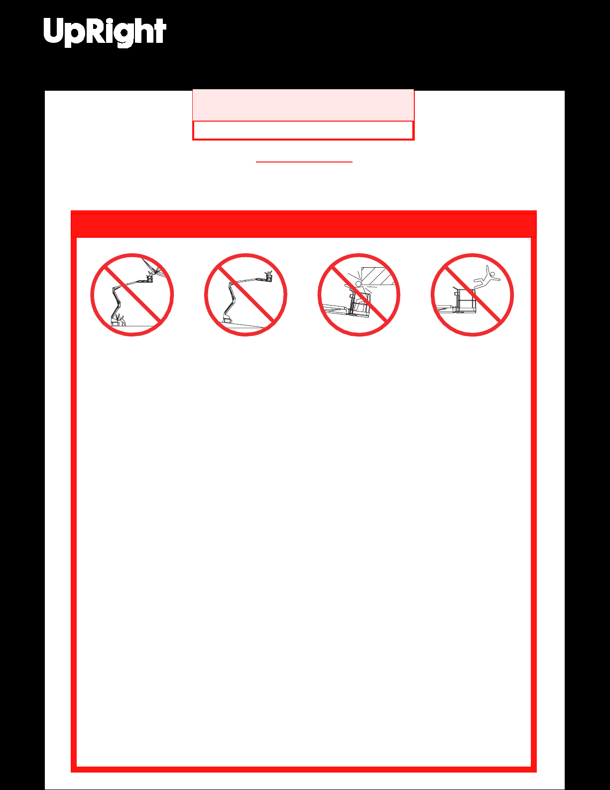
Electrocution Hazard Tip Over Hazard Collision Hazard Fall Hazard
Safety Rules and Operating Instructions
NEVER operate the
machine within ten (10)
feet of power lines. THIS
MACHINE IS NOT
INSULATED.
ALL occupants must wear an approved fall restraint properly attached to designated platform anchorage
point. Attach only one fall restraint to each anchorage point.
NEVER exceed maximum platform load of 500 lbs. (225 kg) and two (2) occupants.
NEVER exceed 45 lbs. (200 N) of side force per occupant.
DISTRIBUTE all platform loads evenly on the platform.
NEVER operate the machine without first surveying the work area for surface hazards such as holes, drop-
offs, bumps, curbs, or debris; and avoiding them.
OPERATE machine only on surfaces capable of supporting wheel loads.
NEVER elevate the machine when wind speeds exceed 28 mph (12.5 m/sec.).
IN CASE OF EMERGENCY push emergency stop button to cut power to all powered functions.
ALWAYS close and secure gate after entering platform.
NEVER exit or enter platform while elevated.
NEVER use ladders, scaffolding, or other items to gain height; work only from the platform floor.
NEVER climb down elevating assembly while platform is elevated.
INSPECT the machine thoroughly for cracked welds, loose or missing hardware, hydraulic leaks, loose
wire connections, and damaged cables or hoses before using.
VERIFY that all labels are in place and legible before using. Refer to page 11 & 12 for label identification.
NEVER use a machine that is damaged, not functioning properly, or has damaged or missing labels.
IF ALARM SOUNDS while boom is elevated, STOP, carefully retract boom and lower platform without
rotating. Move machine to a firm, level surface.
NEVER attach overhanging loads or use boom as a crane.
NEVER alter operating or safety systems without manufacturers written consent.
NEVER charge battery near sparks or open flame. Charging batteries emit explosive hydrogen gas.
NEVER replace any component or part with anything other than original UpRight replacement parts
Safety Rules and Operating Instructions
without the manufacturer's written consent.
NEVER tow the machine. Transport by truck or trailer only.
AFTER USE, secure the work platform from unauthorized use by turn ing both keyswitches off and removing all keys.
Gasoline and diesel engine exhaust and some of their constituents are known to the State of California to cause
NEVER operate the
boom or drive with
platform elevated
unless on firm level
surface.
cancer, birth defects, and other reproductive harm.
NEVER position the
platform without first
checking for overhead
obstructions or other
hazards.
California Proposition 65 Warning
1
NEVER climb, stand or
sit on platform guardrails or midrail.
Page 2
Introduction
This manual covers the operation of internal combustion powered models of the AB-46 RT Articulated
Boom. This manual must be stored on the machine
at all times.
Pre-Operation and Safety
Inspection
Carefully read, understand and follow all safety
rules, labels, and operating instructions, then
perform the following steps each day before use.
Perform a complete visual inspection of the entire
unit prior to operating. Check the following areas for
discrepancies:
1. Open panels and check hydraulic components / hoses
for damage or leaks. Check electrical components /
wiring for damage or loose connections.
2. Inspect chassis, axles, hubs, and steering linkage
for damage, deformation, buckled paint, loose or
missing hardware, and cracked welds.
3. Check tires for damage, punctures, and inflation;
tire pressure must be 55 psi.
4. Check all hoses / cables for wear.
5. Inspect elevating assembly for damage, deformation, buckled paint, loose or missing hardware,
and cracked welds.
6. Inspect platform and guardrails for damage,
deformation, buckled paint, loose or missing
hardware, and cracked welds. Insure that gate
operates freely and latches securely.
7. Check Hydraulic fluid level with platform fully
lowered.
8. Check battery fluid level (see battery maintenance, page 9).
9. Check fuel level, add fuel if necessary (see
fueling, page 9).
10.Ensure that radiator is cold, check coolant level.
Add if necessary.
NEVER remove the cap from a hot radiator.
Hot coolant can cause severe burns.
2. Turn chassis key switch to chassis, and turn on
(rotate clockwise) emergency stop switches at the
chassis control panel and at the platform control
panel.
3. Press the engine start button to crank the engine;
release when engine starts. If engine is cold:
press the preheat button and hold for six seconds
prior to starting diesel models.
4. Push in the chassis emergency stop button
engine should stop. Repeat for platform emergency stop button. Return both emergency stop
buttons to the on position, and start engine.
5. Operate each function switch to raise / lower,
extend / retract, rotate left / right, each section of
the elevating assembly and observe the operation
of the machine. All functions should operate
through full cycle smoothly.
6. Turn chassis key switch to platform.
7. Mount the platform, close and latch the gate, and
attach approved fall restraint to designated platform
anchorage point. Attach only one fall restraint to
each point.
8. Start the engine.
9. Without depressing the foot switch, move the drive
control handle, machine should not function.
10.Depress the foot switch and move the drive
control handle forward and reverse. Observe that
proportional functions operate smoothly, and that
brakes apply quickly after control is released.
11.While depressing foot switch, operate steer
switch to left and right. Observe that steering
wheels turn properly.
12.While depressing foot switch, turn function speed
control knob to desired setting, and operate boom
controls. Observe that boom operates smoothly,
and that upper boom, jib, turret rotation, platform
level, and platform rotation controls operate
proportionally in conjunction with function speed
control knob. Observe that platform maintains
level when boom is elevated.
13.With the upper boom elevated one foot, operate
drive control handle. Observe that drive speed is
limited to creep approximately (1 foot [.3m] per
second). Lower upper boom to stowed position.
14.Press the service horn button. Observe that horn
is audible.
SYSTEM FUNCTION INSPECTION
Note: Refer to figures 1 and 2 for chassis and
platform control locations.
1. Before performing the following tests, check area
around machine and overhead for obstructions,
holes, drop-offs, and debris.
DO NOT use a machine that is damaged or
malfunctioning. Tag and remove the unit
from service until it is repaired.
2
Page 3
Controls and Indicators
Operation
2
1
6
7
10
Figure 1: Chassis Controls
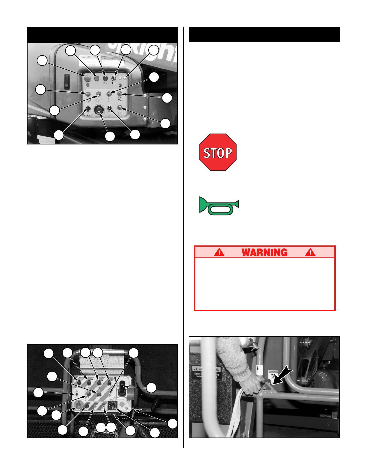
Note: The following list corresponds to the
numbered items in figures one and two.
1. Emergency stop.
2. Engine start.
3. Speed Selector.
4. Keyswitch.
5. Control fuses.
6. Riser control.
7. Upper boom control.
8. Boom extension control.
9. Jib control.
10.Turret rotation control.
11.Platform rotation control.
12.Platform level control.
13.Hourmeter.
14.Service horn button.
15.Drive control handle.
16.Function speed control.
17.Fuel selector (dual fuel).
18.Foot switch (located on platform floor).
19.Out of level indicator.
20.Preheat button (diesel).
20
13
4
11
5
8
12
Before operating work platform insure that:
Pre-operation and safety inspection has been
completed, and any discrepancies have been
corrected.
The operator has been thoroughly trained on the
operation of the machine.
9
The work area is clear of all obstructions, holes,
drop-offs, or persons in the route of travel.
The surface is capable of supporting wheel loads.
Refer to figures one and two for control locations.
Emergency Stop
At any time during operation, press the emergency
stop button to stop all functions in an emergency.
Service Horn
At any time during operation, press the service horn
button to sound an audible warning if necessary.
Always wear an approved fall restraint
properly attached to designated platform
anchorage point when driving or elevating the
machine (see figure 3).
Attach only one fall restraint to each anchorage point.
19
10
8
6
7
11
1
14
Figure 2: Platform Controls
9
20
17
3
12
5
15
4
16
Figure 3: Typical Fall Restraint Anchorage Point
3
Page 4

Starting the engine
From the lower controls
1. Turn the chassis key switch to chassis position.
2. Press the start button to crank the engine. Release when the engine starts.
3. When the engine is cold: press and hold the
preheat button while starting the diesel engine.
Note: Do not depress the foot switch when
cranking engine, as this may flood engine.
From the platform controls
1. Turn the chassis key switch to platform controls.
2. Turn the platform keyswitch fully clockwise to
crank the engine. Release when engine starts.
3. When the engine is cold: Press and hold the
preheat button while starting the diesel engine.
Note: Do not depress the foot switch when
cranking engine, as this may flood engine.
3. Attach approved fall restraint to designated
platform anchorage point. Attach only one fall
restraint to each point.
4. Start engine.
5. Check that the area around and above the work
platform is clear of obstructions, holes, drop-offs,
persons in the route of travel, and the surface is
capable of supporting wheel loads.
6. Examine the terrain and place the speed selector
switch in the appropriate position (Hi or Lo).
7. Depress the foot switch and move the drive
control handle forward to travel forward and
reverse to travel in the reverse direction.
8. While driving in HI speed, pressing the button,
located on the front of the drive control handle,
will shift momentarily into LO for improved torque.
Note: When the boom is rotated to the front of
the chassis (steering wheels aft) directions of
travel and steering will be reversed. Observe the
color coded arrows on the control panel near the
drive control handle, and on the chassis. They
will indicate the direction of travel when the drive
control handle is moved.
Driving
With Boom Lowered
The AB-46 RT has two drive speeds when the
boom is lowered to efficiently accommodate varying
terrain.
Lo Speed: The Lo speed capability allows the
machine to be easily maneuvered
through rougher terrain and negotiate
steeper slopes.
Hi Speed: The Hi speed capability is convenient
for maneuvering in areas that are
relatively smooth and where the
machine will not be driven over rough
or sloping tereain.
Turn chassis key switch to platform, and turn on (turn
1.
clockwise) the chassis emergency stop switch.
2. Mount the platform, close and latch the gate.
The front axle will oscillate freely through a
limited range when driving for greater ease of
negotiating irregular terrain.
With Boom Elevated
Travel with boom elevated is restricted to firm
level surfaces only. When the articulating front
axle is not level, it will lock into position and
disable the drive function.
When driving elevated, the machine will travel at
creep speed (1 foot [.3 m] per second).
Steering
1. While depressing the foot switch, push the steering
switch (located on top of the control handle) to the
left to turn left, and right to turn right.
Note: Steering is not self centering. Wheels
must be returned to the straight ahead position
by operating the steering switch.
POSITIONING THE PLATFORM
Positioning the platform as close as possible to the
work area requires some planning. First, you must
survey the work site to find a suitable place to park
the machine. This must be a firm level area as close
as possible to the work area. Take into consideration all obstructions on the ground and overhead
and avoid them.
4
Page 5
Once you have moved the machine to a firm level
surface as near as possible to the work area, follow
the instructions on page five to position the platform
as close to the work area as possible.
Always, before operating any function, check the
area around and overhead for any obstructions or
electrical conductors.
NEVER exit the platform while the boom is
elevated. Keep both feet firmly planted on
the platform floor at all times.
Multifunction Controls
The UpRight AB-46 RT employs the use of
multifunction controls. This means that riser or boom
extension will function at full speed while
simultaneously operating upper boom, jib, turret, or
rotating the platform.
The turret may be rotated while driving when boom is
lowered if necessary to make turns in tight areas.
No other boom functions will operate while driving.
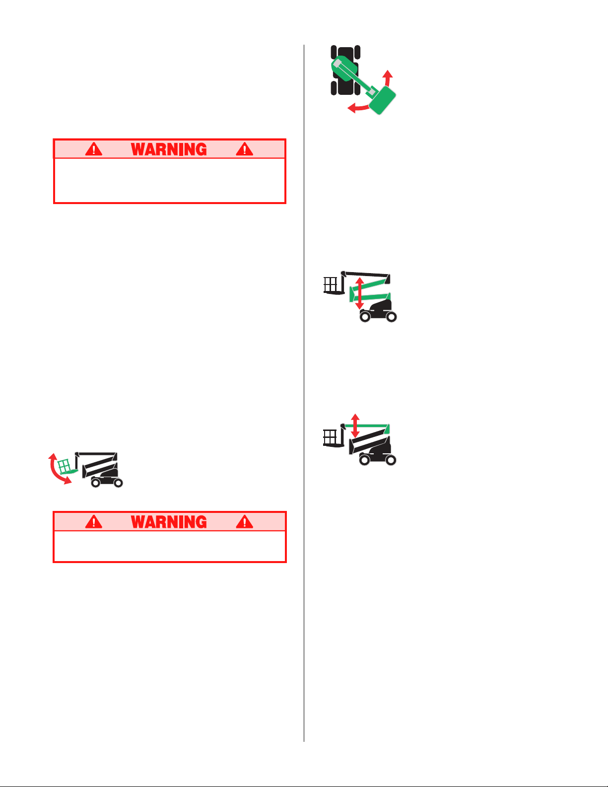
Rotating the Turret
1. Set the function speed control dial to the desired
setting. Rotate the dial clockwise to increase
speed, counterclockwise to decrease. If you are
not sure what speed to use, start out slow; the
speed can be varied while operating the function.
2. While depressing the foot switch, turn the turret
rotation control switch counterclockwise to rotate
left, clockwise to rotate right. Release the switch
to stop rotation. Observe the area around the
boom when rotating the turret to avoid any obstructions.
Elevating the Riser
Lower Control Operation
All boom functions will operate at fixed speed. Those
which are adjustable will operate at the speed set on
the platform control.
1. Turn chassis keyswitch to chassis controls.
2. With engine running, operate boom control
switches to position the platform.
Leveling the Platform
DO NOT operate the machine if the platform
does not maintain level when elevated.
Note: Platform leveling can be performed only
with the boom stowed and should be done only
to calibrate the automatic leveling system.
1. Set the function speed control dial to the desired
setting. Rotate the dial clockwise to increase
speed, counterclockwise to decrease. If you are
not sure what speed to use, start out slow; the
speed can be varied while operating the function.
2. While depressing the foot switch, push the
platform level control switch forward to swing the
platform upward, rearward to swing the platform
downward. Release the switch to stop leveling.
1. While depressing the foot switch, push the riser
control lever forward to elevate the riser, rearward
to lower the riser. Release the control lever to
stop elevating / lowering. The riser will function at
a constant speed, function speed control setting
is not necessary.
Elevating the Upper Boom
1. Set the function speed control dial to the desired
setting. Rotate the dial clockwise to increase
speed, counterclockwise to decrease. If you are
not sure what speed to use, start out slow; the
speed can be varied while operating the function.
2.
While depressing the foot switch, push the upper
boom control lever forward to elevate the upper
boom, rearward to lower the upper boom. Release
the control lever to stop elevating / lowering.
5
Page 6
Extending the Upper
Boom
1. While depressing the foot switch, push the boom
extension control lever rearward to extend the
boom, forward to retract the boom. Release the
control lever to stop extending / retracting. The
boom extension will function at a constant speed,
function speed control setting is not necessary.
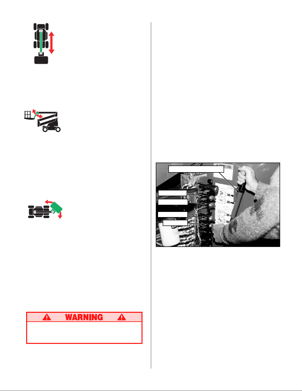
Lowering Elevating Assembly
1. Open the cover on the hydraulic module (opposite
side of the turret from the chassis control panel).
2. Remove the wire loop retainer from the hand
pump lever, and extend the handle upward to
gain leverage.
3. Operate the manual override (knurled knob) on the
appropriate valve (see fig. 4). Push in to lower /
extend, pull out to raise / retract as required.
4. While holding the appropriate valve in position,
pump the handle in and out until that section of
the elevating assembly is lowered / retracted.
5. Repeat as necessary operating each valve until
the elevating assembly is fully lowered.
Elevating the Jib
1. Set the function speed control dial to the desired
setting. Rotate the dial clockwise to increase
speed, counterclockwise to decrease. If you are
not sure what speed to use, start out slow; the
speed can be varied while operating the function.
2. While depressing the foot switch, push the jib
control lever forward to elevate the jib, rearward
to lower the jib. Release the control lever to stop
elevating / lowering.
Rotating the Platform
1. Set the function speed control dial to the desired
setting. Rotate the dial clockwise to increase
speed, counterclockwise to decrease. If you are
not sure what speed to use, start out slow; the
speed can be varied while operating the function.
2. While depressing the foot switch, turn the platform rotation control switch counterclockwise to
rotate left, clockwise to rotate right. Release the
switch to stop rotation.
EMERGENCY OPERATION
In the event of powered function failure, the elevating
assembly may be lowered manually by the following
procedure.
NEVER climb down the elevating assembly.
If controls do not respond, ask someone on
the ground to lower the boom manually.
Note: Use of the hand pump causes a diverter
valve to open disabling normal controls. The
valve will remain open until pressure is bled off.
After operating any function with the hand pump,
cycle the jib valve in and out 6 times to bleed off
pressure.
Emergency control
pump
Riser Valve
Extend
Valve
Boom Valve
Jib Valve
Figure 4: Emergency Control Operation
Rotating Turret
1. To manually rotate the turret, remove the manual
turret crank from inside of the control side turret
cover.
2. Set ratchet direction on turret crank.
3. Place the socket of the crank onto the hex shaft
stub of the turret rotation gearbox.
4. Turn the crank clockwise to rotate the turret
counterclockwise, turn counterclockwise to rotate
the turret clockwise.
6
Page 7
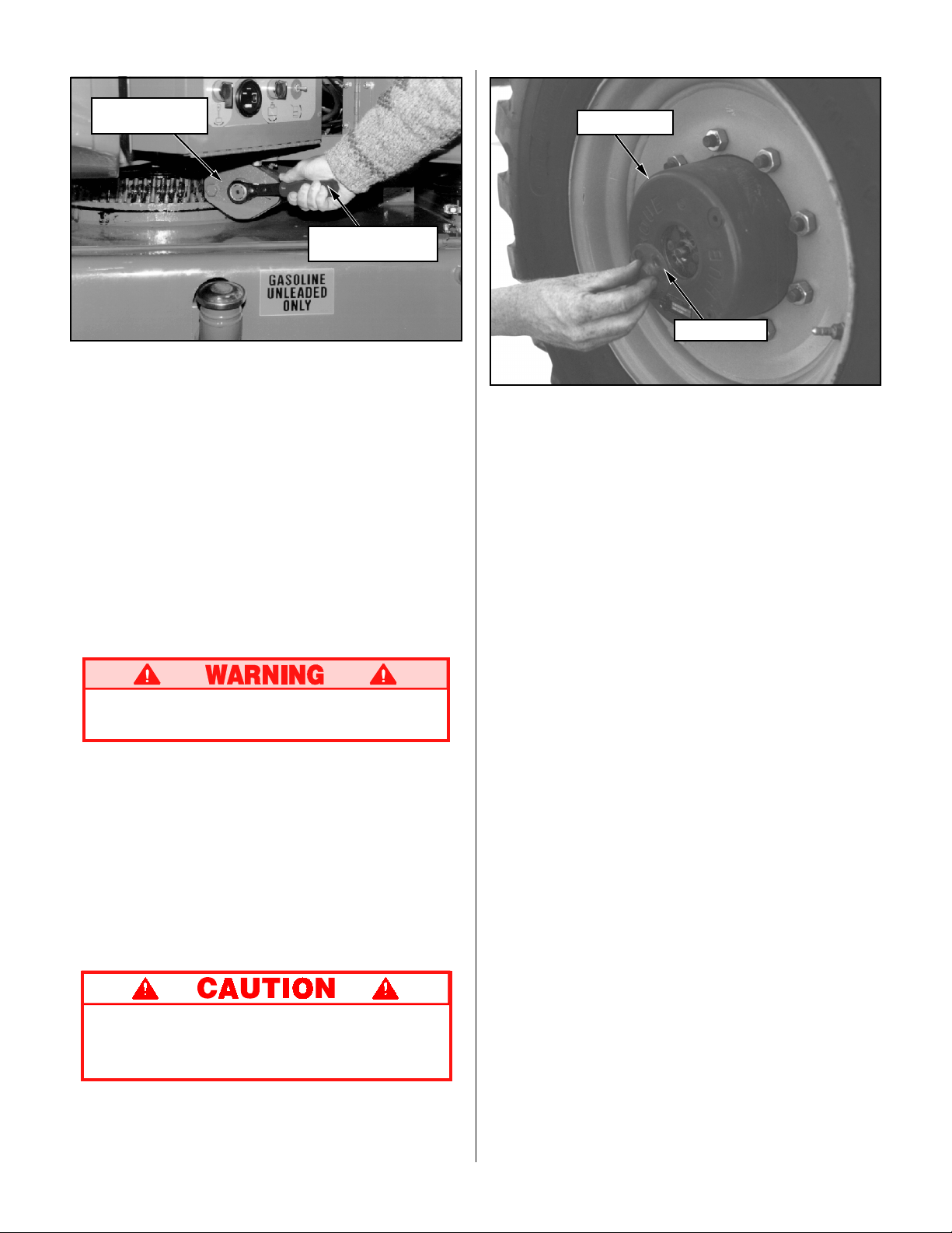
Turret Rotation
Gear Box
Figure 5: Manual Turret Rotation
EMERGENCY TOWING
7
/8 in. Ratcheting
Wrench
Drive Hub
Center Cap
Figure 6: Disengaging Drive Hub
Perform the following only when the machine will
not operate under its own power and it is necessary to move the machine or when winching onto a
trailer for transportation.
1. Insure that the platform is fully lowered, and that
the turret is rotated so that the platform is to the
rear of the machine.
2. Attach chain / cable of sufficient strength for
towing the machine to front or rear tie down lugs.
Chock wheels before disengaging hubs.
Machine may roll.
3. Refer to figure 6 and disengage all four drive
hubs. Remove two screws and center cap.
Reinstall center cap in the opposite direction.
4. When ready to move the machine, remove the
chocks. Tow or winch into position and replace
chocks.
5. Engage all four drive hubs by returning the center
caps to their original orientation.
AFTER USE EACH DAY
1. Ensure that the platform is fully lowered.
2. Park the machine on level ground, preferably
under cover, secure against vandals, children or
unauthorized operation.
3. Turn the upper key switch to OFF, the lower key
switch to platform and remove all keys to prevent
unauthorized operation.
DO NOT move the machine faster than 3
mph. Faster speeds will damage drive
components and void warranty.
7
Page 8
Transportation
BY CRANE
Stand clear of machine when lifting.
Check specifications on back page, insure
that crane and slings are of correct capacity
to lift weight of unit.
1. Insure that boom is fully lowered and retracted.
2. Attach straps to chassis lifting lugs only. Insure
that straps are adjusted properly to keep unit
level when lifting.
BY TRUCK OR TRAILER
1. Insure that boom is fully lowered and retracted.
2. Maneuver the machine onto bed of truck / trailer.
3. When winching, follow instructions for emergency
towing on page 7. Attach winch cable to front tie
down lugs.
Do not winch machine faster than 3 mph.
4. After winching, insure that brakes are set.
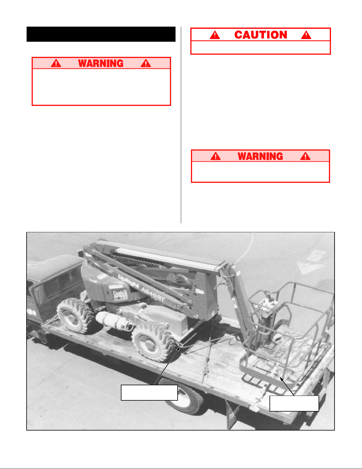
5. Secure the machine to the transport vehicle using
chains / straps of adequate load capacity (refer to
specifications, back page) attached to chassis tie
down lugs (see figure 7).
6. Place a wooden block (10.5" x 6" x 35") under
platform support braces as shown (see figure 7).
7. Attach ratchet strap; under platform floor grating,
over support braces (see figure 7). Tighten
securely, do not overtighten.
NEVER elevate the machine while on a truck
or trailer.
Chassis Tie Down
Lifting Lug (typ.)
Figure 7: Securing the Machine for Transportation
8
Wooden Block
10.5" x 6" x 35"
Page 9
FUELING
Maintenance
BATTERY MAINTENANCE
Gasoline
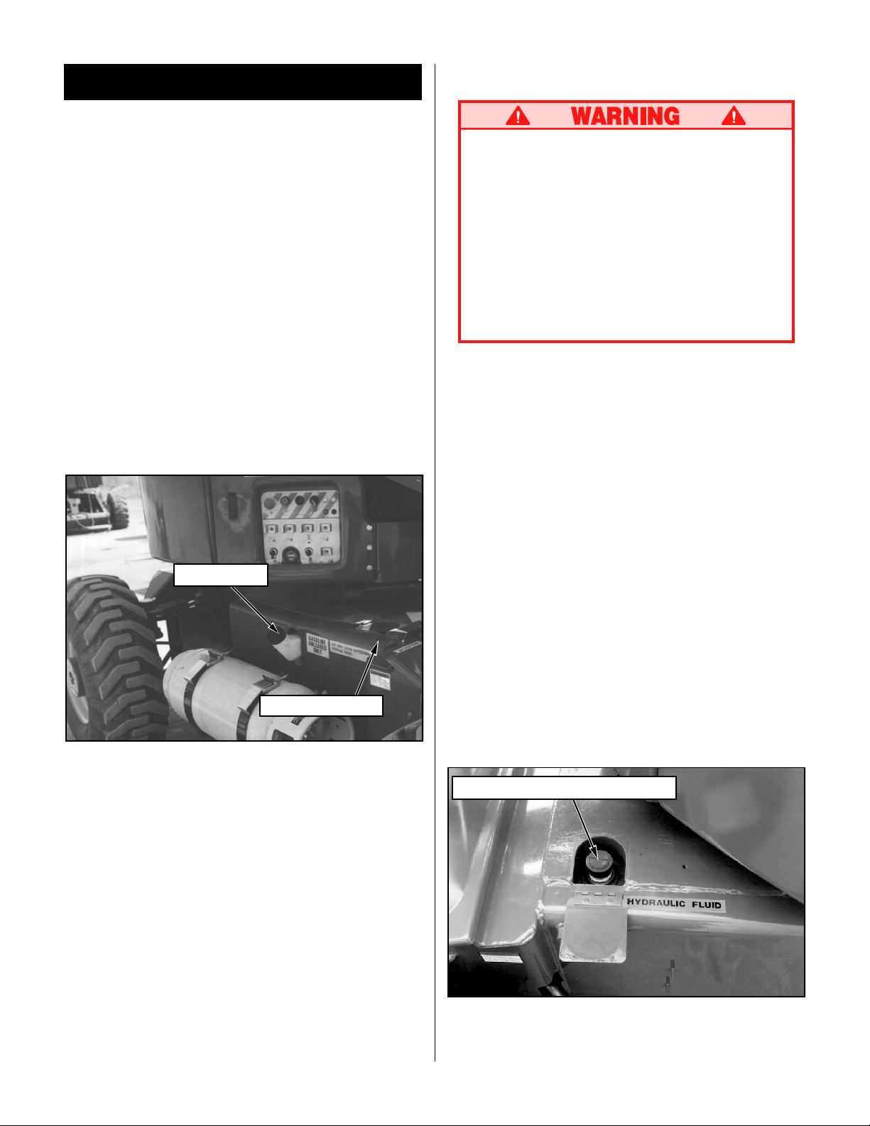
1. Open fill pipe cap located on chassis left side
(see figure 8).
2. Fill to capacity with unleaded motor fuel only.
3. Check fuel level by lifting flap located on top of
chassis left side (see figure 8). Fuel tank full
capacity is 25 US gallons.
Diesel
1. Open fill pipe cap located on chassis left side
(see figure 8).
2. Fill to capacity with diesel motor fuel only, grade
#1-D, or #2-D. Use distillate fuel only, do not use
residual or blend.
3. Check fuel level by lifting flap located on top of
chassis left side (see figure 8). Fuel tank full
capacity is 25 US gallons.
Hazard of explosive gas mixture. Keep
sparks, flame and smoking materials away
from batteries.
Always wear safety glasses when working
with batteries.
Battery fluid is highly corrosive. Rinse away
any spilled fluid thoroughly with clean water.
Always replace batteries with UpRight batteries or manufacturer approved replacements
weighing 62 lbs. each.
Check battery fluid level daily, especially if work
platform is being used in a warm, dry climate.
If electrolyte level is lower than 3/8 in. (10 mm)
above plates add distilled water only. DO NOT use
tap water it will shorten battery life.
Keep terminals and top of battery clean.
TIRES
Tire selection can affect the stability of the machine.
Use only tires supplied by UpRight unless approved
by the manufacturer in writing.
Fuel Fill Pipe
Fuel Level Gauge
Figure 8: Fuel Fill Pipe and Level Gauge
HYDRAULIC OIL
1. Check oil level at sight gauge inside engine
compartment right hand side with the platform
fully lowered.
2. If necessary, fill to capacity with clean ISO 46
compatible hydraulic oil.
3. Lift flap located on top of chassis right side (see
figure 9).
4. Open filler / breather cap to add hydraulic oil.
5. Replace cap.
Hydraulic Oil Filler / Breather Cap
LUBRICATION
Refer to service manual for lubrication chart and
guidelines.
Figure 9: Hydraulic Oil Filler / Breather Cap
9
Page 10
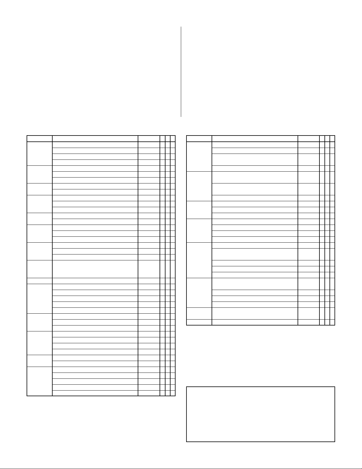
ROUTINE SERVICE
Use the following table as a guide for routine maintenance. Inspection and maintenance shall be
performed by personnel who are trained and
familiar with mechanical and electrical procedures. Refer to the Service Manual for complete
service instructions.
Please copy this page and use the Routine Service
Table as a checklist when inspecting a machine for
service.
Routine Service Table
Routine Service Table Key
Interval
Daily=each shift (every day) or every eight hours
30
D
=every month (30 days) or every 50 hours
3
M
=every 3 months or 125 hours
6
M
=every 6 months or 250 hours
1
Y
=every year or 500 hours
2
Y
=every 2 years or 1000 hours
Y=Yes/Acceptable
N=No/Not Acceptable
R=Repaired/Acceptable
COMPONENT INSPECTION OR SERVICES INTERVAL Y N R
Engine Oil Check level and condition Daily
Engine Fuel Check fuel level Daily
System Check for leaks Daily
Engine Air Replace air cleaner 6
Cleaner Check air cleaner Daily
Battery Check electrolyte level Daily
Engine Check coolant level (with engine cold) Daily
Coolant Replace coolant 3
Hydraulic Check oil level Daily
Oil Change filter 6
Hydraulic Check for leaks Daily
System Check hose connections 30
Emergency Check operation of emergency override Daily
Hydraulic valves and hand pump
System
Controller Check operation of all controls Daily
Platform Check fasteners for proper torque Daily
Floor and Check welds for cracks Daily
Rails Check condition of platform Daily
Tires Check for damage Daily
Hydraulic Wipe clean 30
Pump Check for leaks at mating surfaces 30
Hydraulic Check hydraulic drive motor operation Daily
Drive System
Steering Check fittings for proper torque 6
System Oil all pivot points 30
Check for leaks Daily
*Change oil & filter (Dual Fuel) 100
*Change oil & filter (Diesel) 200
Replace fuel filter 6
Clean exterior 3
Clean terminals 3
Drain and replace with ISO 46 compatible oil 2
Check hoses for exterior wear 30
Check condition of anchorage points Daily
Check condition of operators manual Daily
Check air pressure (55 psi) Daily
Check lug nuts (torque to 90 ft. lbs. [123 Nm]) 30
Check for hose fitting leaks Daily
Check mounting bolts for proper torque 30
Check hoses, fittings, and valve block for leaks Daily
Check steering cylinder for leaks 30
Check linkage for wear areas 30
Check for missing / loose retainers Daily
HOURS
HOURS
M
M
M
M
M
M
Y
M
D
D
D
D
D
D
D
D
D
COMPONENT INSPECTION OR SERVICES INTERVAL Y N R
Elevating Inspect for structural cracks Daily
Assembly Check pivot points for wear 30
Chassis Check hoses for pinch or Daily
Turret Check ring gear for proper lubrication and wear Daily
Drive Check for leaks Daily
Hubs Check oil level 250H/6
Lift Check the cylinder rods for wear 30
Cylinders Check pivot pin retaining bolts 30
Entire Check for and repair Daily
Unit collision damage
Labels Check for peeling, missing, or unreadable Daily
Slew Ring Check fasteners for proper torque 30
Check pivot pin retaining bolts 30
for proper torque
Check members for deformation Daily
rubbing points
Check component mounting 6
for proper torque
Check welds for cracks Daily
Lubricate worm gear bearings 150H/3
Lubricate ring gear (MoS
Change oil after break-in period 50H/30
Change oil (SAE 90 wt. gear oil) 2000H/2
for proper torque
Check seals for leaks 30
Inspect pivot points for wear 30
Check fittings for proper torque 30
Check fasteners for proper torque 3
Check for corrosion, remove and repaint 3
Lubricate 30
labels & replace
grease) 150H/3
2
D
D
M
M
M
M
D
Y
D
D
D
D
D
M
M
D
D
* First oil change after 50 hours.
Service Report
Date: _______________
Owner: _________________________________
Model No: ____________ Serial No: __________
Serviced By: _____________________________
Service Interval: __________________________
10
Page 11
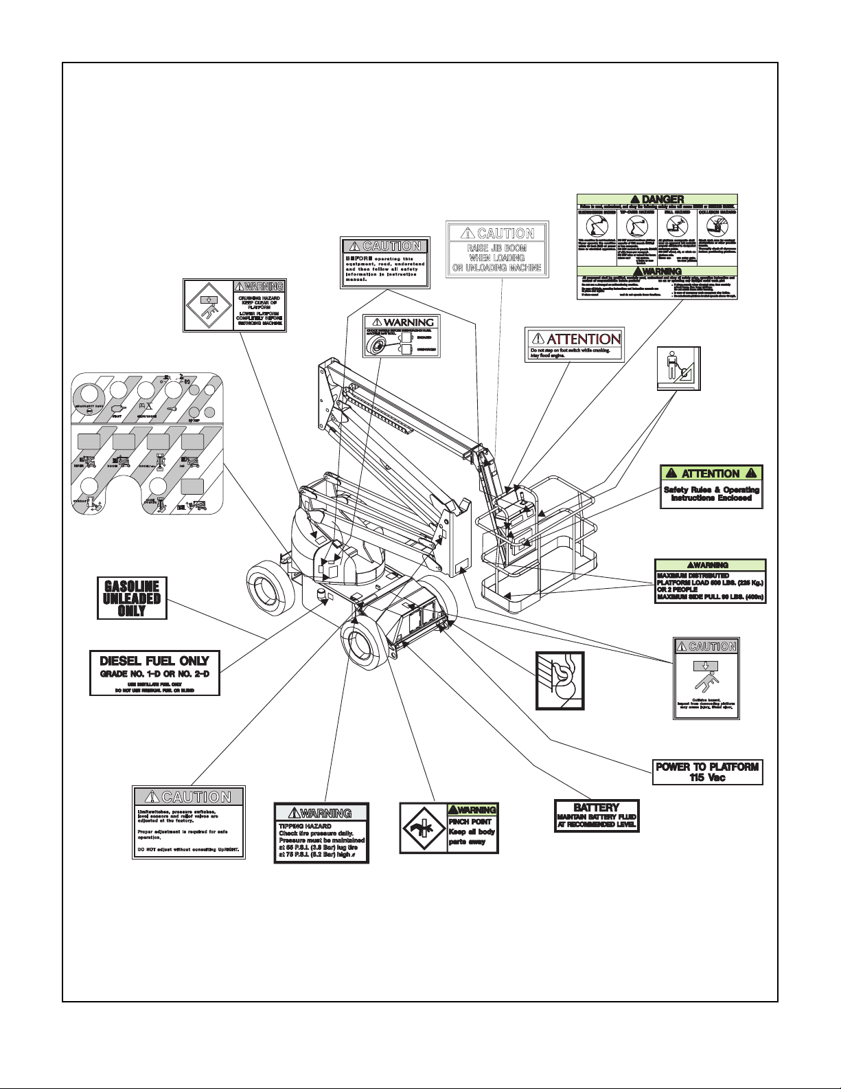
Note: Labels can be ordered by using Part Number located by each label.
For machines equipped with options, consult the Service Manual.
068649-000
1 REQUIRED
068980-000
1 REQUIRED
068587-010
1 REQUIRED
066568-000
2 REQUIRED
066544-000
3 REQUIRED
068979-000
1 REQUIRED
068633-000
1 REQUIRED
068635-000
2 REQUIRED
010076-001
1 REQUIRED
064166-000
1 REQUIRED
(GASOLINE MODEL
ONLY)
027898-000
1 REQUIRED
(DIESEL MODEL ONLY)
066555-000
2 REQUIRED
006652-001
2 REQUIRED
066553-004
5 REQUIRED
068635-000
4 REQUIRED
005221-000
1 REQUIRED
062557-012
2 REQUIRED
066556-000
2 REQUIRED
068639-000
1 REQUIRED
Figure 9: Label Identification
11
Page 12
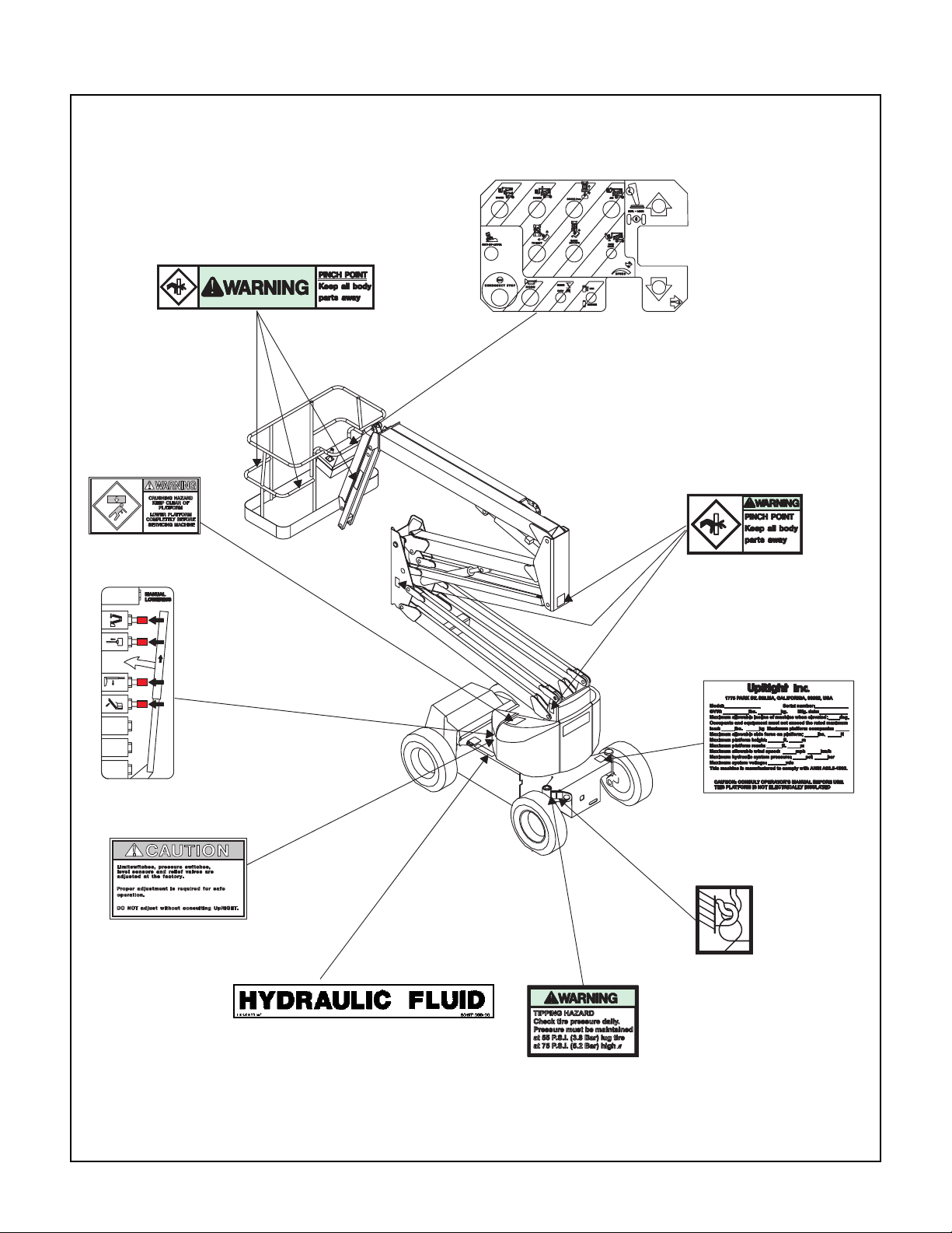
Figure 9: Label Identification (cont.)
066568-000
2 REQUIRED
066553-001
3 REQUIRED
068586-004
068586-003
1 REQUIRED
(GAS MODELS)
(DIESEL MODELS)
066553-004
5 REQUIRED
068634-000
1 REQUIRED
(INSIDE)
066555-000
2 REQUIRED
(INSIDE)
060197-000
1 REQUIRED
068635-000
4 REQUIRED
006652-001
4 REQUIRED
061205-002
1 REQUIRED
AB - 46 Label Installation: All of the labels shown in figure 9 shall be present and in
good condition before operating the work platform. Be sure to read, understand and
follow these labels when operating the work platform.
12
Page 13

NOTES:
13
Page 14

NOTES:
14
Page 15

NOTES:
15
Page 16
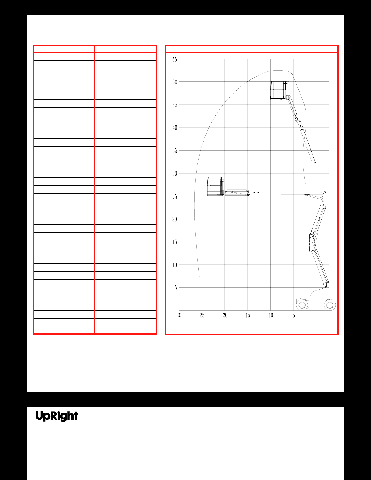
Specifications*
ITEM SPECIFICATION
Height
Working height maximum 52 ft. 10 in.
Platform height maximum 46 ft. 10 in.
Platform step in height 19 in.
Up and over height 25 ft. 8 in.
Drivable height 46 ft. 10 in.
Horizontal outreach 24 ft. 6 in.
Turret rotation 360 deg. noncontinuous
Platform rotation 160 deg.
Tail swing None
Jib length 5 ft.
Jib arc 140 deg.
Inside turning radius 3 ft.
Outside turning radius 12 ft.
Drive speed (lowered) 4.5 mph
Drive speed (elevated) .6 mph
Gradability 40%
Platform Size 69 in. x 39 in.
Guardrail height 43
Toeboards 6 in.
Maximum platform capacity 500 lbs.
Maximum no. of occupants 2
Weight (Gas Model) 14,460 lbs.
Weight (Diesel Model) 14,660 lbs.
Overall height 7 ft. 4 in.
Overall length 18 ft. 4 in.
Overall width 6 ft. 7 in.
Wheel base 7 ft. 2 in.
Wheel track 5 ft. 5 in.
Ground Clearance 13 in.
Power source (Gas Model) Ford VSG 413
Power source (Diesel Model) John Deere 3015DF
System voltage 12VDC
Maximum Hyd. Pressure 5000 psi
Controls Electric Proportional
Tires 14x17.5 10 ply lug tread
1
/2 in.
Safety Rules and Operating Instructions
REACH ENVELOPE DIAGRAM
DIMENSIONS IN FEET
* Specifications subject to change without notice.
Refer to Service Manual for complete parts and service information.
Meets or exceeds all applicable requirements of OSHA and ANSI A92.5-1992
FOR MORE INFORMATION
Local Distributor:
Safety Rules and Operating Instructions
TEL: (1) 800-926-5438 or (1) 559-662-3900
FAX: (1) 559-673-6184
Parts FAX: (1) 800-669-9884
801 South Pine Street
Madera, California 93637
http://www.upright.com
16
068342-003
07-02
 Loading...