

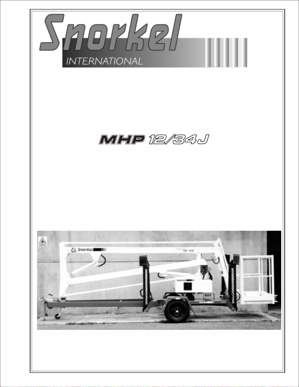
Page 1
Operator’s
Manual
Engine Powered
Gasoline
Battery Electric
P/N 11447A
April 2003
Bi-Energy and Self Level
Page 2

LIMITED WARRANTY
Snorkel warrants each new machine manufactured and sold by it to be free from defectsin material and workmanship fora
periodofone(1)yearfrom dateofdelivery toaCustomeror forone yearafterthe machinehasbeen placedinfirstservicein a
Dealerrentalfleet, whichevercomes first.Any par t or par ts which, upon examinationbythe SnorkelService Department, are
foundtobe defective,willbe replaced or repaired,atthe sole discretion ofSnorkel,through its local Authorized Dealer atno
charge.
Snorkelfurther warrants the structural components;specifically, the mainframe chassis,turntable,boomsandscissorarms,
of each new machine manufactured by it to be freefrom defectsin material and workmanshipforanadditional period of four
(4) years.Any such part or parts which, upon examination by the SnorkelService Department, are found to be defective will
bereplaced or repairedbySnorkel throughitslocal AuthorizedDealerat nocharge;however,anylabor charges incurredasa
result of such replacement or repair will be the responsibility of the Customer or Dealer.
The Snorkel Service Depar tment must be notified within forty-eight (48) hours of anypossible warranty situation during the
applicable warranty period.Personnel performing warranty repair or replacement must obtain specific approval by Snorkel
Service Department prior to performing any warranty repair or replacement.
Customer and Dealer shall not be entitled to the benefits of this warranty and Snorkel shall haveno obligations hereunder
unless the “Pre-Delivery and Inspection Report” has been properly completed and returned to the Snorkel Service
Department within ten (10) days after delivery of the Sorkel product to Customer or Dealer’s rental fleet. Snorkel must be
notified, in writing, within ten (10) days,of any machine sold to a Customer from a Dealer’s rental fleet during the warranty
period.
At the direction of the Snorkel Service Department, any component par t(s) of Snorkel products to be replaced or repaired
underthiswarrantyprogram must be returned freight prepaid to the Snor kel ServiceDepartmentforinspection. Allwarranty
replacement parts willbeshipped freight prepaid (standard ground) fromtheSnorkel Service Department or from Snorkel’s
Vendor to Dealer or Customer.
REPLACEMENT PARTS WARRANTY
Any replacement or service part made or sold by Snorkel is not subject to the preceding Limited Warranty beyond the
normal warranty per iod of the machine upon which the part was installed.
THIS WARRANTY EXCLUDES AND SNORKEL DOES NOT WARRANT:
1. Engines, motors, tires and batteries whichare manufactured by suppliers to Snorkel, whofurnish their own warranty.
Snorkelwill, however,tothe extentpermitted,passthroughany suchwarrantyprotectiontothe CustomerorDealer.
2. AnySnorkelproduct whichhasbeenmodified or altered outside Snorkel’sfactory without Snorkel’swritten approval,if
suchmodification or alteration, in thesolejudgment of Snorkel’sEngineering and/or ServiceDepartments, adversely
affects the stability, reliability or service life of the Snorkel product or any component thereof.
3. AnySnorkelproductwhich hasbeensubjectto misuse,improper maintenanceoraccident.“Misuse”includesbutisnot
limited to operation beyond the factory-rated load capacity and speeds.“Improper maintenance” includes but is not
limited to failure to follow the recommendations contained in the Snorkel Operation, Maintenance, Repair Parts
Manuals.Snorkelis not responsiblefornormal maintenance, service adjustments andreplacements,including but not
limited to hydraulic fluid, filters and lubrication.
4. Normalwearofany Snorkel componentpart(s).Normalwear of componentparts mayvarywiththe type application or
type of environment in which the machine may be used;such as, but not limited to sandblasting applications.
5. Any Snorkel product that has come in direct contact with any chemical or abrasive material.
6. Incidental or consequential expenses,losses, or damages related to any part or equipment failure, including but not
limited to freight cost to transport the machine to a repair facility, downtime of the machine, lost time for workers,lost
orders, lost rental revenue, lost profits or increased cost.
This warrantyisexpresslyinlieuofallother warranties,representationsorliabilitiesof Snorkel, either expressedor implied,
unless otherwise amended in writing by Snorkel’s President, Vice President-Engineer ing, Vice President-Sales or Vice
President-Marketing.
SNORKEL MAKES NO WARRANTIESWHICH EXTEND BEYONDTHE DESCRIPTION OF THIS LIMITED WARRANTY.
SNORKEL MAKES NO IMPLIED WARRANTYOF MERCHANTABILITYOR FITNESS FOR A PARTICULARPURPOSE
AND DISCLAIMS ALL LIABILITY FOR INCIDENTAL OR CONSEQUENTIAL DAMAGES, INCLUDING BUT NOT
LIMITED TO INJURY TO PERSONS OR PROPERTY.
The Customer shall make all warranty claims through its local AuthorizedDealer and shouldcontact the Dealerfrom whom
the Snorkel product was purchased for warranty service. Or, if unable to contact the Dealer, contact the Snorkel Service
Department for further assistance.
Effective July 1995
Page 3
■
Electrical Hazard Warning
THE SNORKELIFT AERIAL WORK PLATFORM
IS NOT ELECTRICALLY INSULATED.
Electrical Hazard
DANGER
If the platform, booms, or any other conductive part of a Snorkelift contacts a high-voltage electrical con
ductor, the result can be SERIOUS INJURY or DEATH for persons on or near the machine.
GO NO CLOSER THAN THE MINIMUM SAFE APPROACH DISTANCES
(M.S.A.D) - AS OUTLINED IN TABLE 1. AND FIGURE 3.,
ON THE NEXT PAGE.
Be sure to allow for sag and sway in the wires and the work platform.
If a Snorkelift comes in contact with a live electrical conductor, the entire machine can be charged.
If that happens, you should remain on the machine and not contact any other structure or object within
reach. That includes the ground, adjacent buildings, poles, and any object not a part of the Snorkelift.
Suchcontact could makeyourbody aconductor to theother objectcreating an electricalshock hazardre-
sulting in SERIOUS INJURY or DEATH.
DO NOT attempt to enter or leave the Snorkelift until you are sure the electricity has been turned off.
If aSnor kelift is in contactwith a liveconductor, the platform operator MUST warn others on the ground in
the vicinity of the Snorkelift to STAY AWAY from the machine, since their bodies can also form a path for
electricity to ground thus creating an electrical shock hazard with possible ELECTROCUTION and
DEATH.
-
DONOTattempttooperatetheSnorkeliftground controls whentheplatform,booms,oranyother conduct
ingpartofa Snorkeliftisincontact with electricalwiresorifthereisanimmediatedangerofsuchcontact.
Regard all conductors as energized.
Personnel working on or near a Snorkelift must be continuously aware of electrical hazards, recognizing
that SERIOUS INJURY or DEATH can result if contact with an electrical wire does occur.
MHP12/34J – 11447A page - i
-
Page 4
Electrical Hazard
p
■
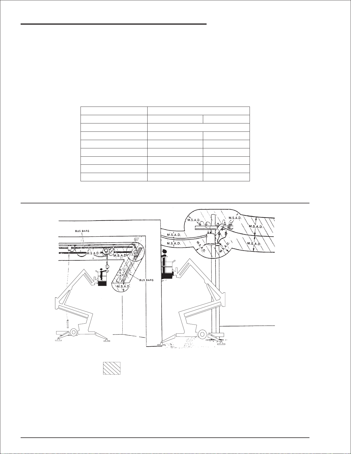
Minimum Safe Approach Distance
TheSnorkeliftis anallmetal boom,NOTELECTRICALLY INSULATED, aerialworkplatform.DO NOTop
erateit nearELECTRICAL conductors.Regard all conductors as beingenergized.Usethe tableand illus
trationbelowtodetermine safeclearance from electricalconductors.(Table1andFigure 3, below,arefrom
ANSI/SIA A92.5–1992 Standard, reprinted with permission of Scaffold Industry Association.)
Table 1 - (M.S.A.D.)
❑
Minimum Safe Approach Distance
to energized (exposed or insulated power lines)
Voltage range Minimum safe approach distance
(phase to phase)
0 to 300V
over 300v to 50kv
over 50kv to 200kv
over 200kv to 350kv
over 350kv to 500kv
over 500kv to 750kv
over 750kv to 1000kv
(Feet) (Meters)
Avoid contact
10
15
20
25
35
45
3.05
4.60
6.10
7.62
10.67
13.72
-
-
Figure 3 - (M.S.A.D.)
❑
Denotes prohibited zone
Danger:
Caution:
page - ii MHP12/34J – 11447A
- Do not allow machine personnel or conductive
materials inside prohibited zone.
- Maintain M.S.A.D. From all energised lines and parts
as well as those shown.
- Assume all electrical parts and wires are energised
unless known otherwise.
- Diagrams shown are only for purposes of illustrating
M.S.A.D. Work
ositions, not all workpositions.
Page 5
Introduction
The most important chapter in this manual is
"Safety" chapter 1. Take time, now, to study it
closely. The information in chapter 1, might save
your life or prevent serious injury.
■
Signs
The following three conventionsare used through
out this manual.
1. Danger sign
DANGER
means:Attention! Become alert! Yoursafety
is involved.
2. Caution sign
CAUTION
meansone oftwothings:(1) an action,about
to be performed, is potentially hazardous
and might result in minor personal injury if
not done correctly,or (2) an action, about to
be performed, can harm the Snorkelift if not
done correctly.
3. Note sign
NOTE
means: The information following is to assist you
in either the proper steps to take for an action or
as additional information concerning your present
situation, but does not indicate a dangerous
condition to either you or the Snorkelift unit.
■
Qualified operators
TheSnorkeliftaer ial platformhasbuiltin safetyfea
tures and has been factory tested for compliance
withSnor kel specificationsand industry standards.
However,anypersonnelliftingdevicecanbepoten
tially dangerous in the hands of untrained or care
less operators.
Training is vitally important andMUST be done un
derthe direction ofa QUALIFIEDperson.You must
displayproficiency in knowledge and actual opera
tion of the Snorkelift.
Before operation of the Snorkelift you must read
and understand the operating instructions in this
manual as well as the decals, warnings, and in
structions on the machine itself.
Before operating the Snorkelift you must be
AUTHORIZED by the person in charge to do so.
■
Operation rules
The following rules will help ensure the safety of
personnelandhelppreventneedlessdowntimebe
cause of damaged equipment.
1. Only TRAINED and AUTHORIZED operators
shall be permitted to operate the equipment.
-
2. All manufacturer’s operating instructions and
safety rules and all employers’ safety rules
and all OSHA and other government safety
rules must be strictly adhered to.
3. Repairs and adjustments shall be made only
by QUALIFIED TRAINED maintenance
personnel.
4. No modification shall be made to the
equipment without prior wr itten consent of
the Snorkel Engineering Department.
5. You must make a pre-start inspection of the
Snorkelift at the beginning of each shift. A
malfunctioning machine must not be used.
6. You must make an inspection of the work
place to locate possible hazards before
operating the Snorkelift.
DANGER
DO NOT operate this equipment unless you
are TRAINED and AUTHORIZED and have
read and thoroughly understand all of the
information given in this Operator’s Manual
and on all DANGER and CAUTION signs on
the machine. Misuse of this machine can
result in DEATH or SERIOUS INJURY.
■
-
-
-
-
-
-
Maintenance
Every personwho maintains, inspects,tests, or re
pairs these machines, and every person supervis
ing any of these functions, MUST be properly
trained.
This Operator’s Manualprovides a dailyinspection
procedure that will help youkeep your Snorkelift in
good operating condition. DO NOT perform other
maintenance unless you are a TRAINED me
chanic, QUALIFIED to work on the Snorkelift. Call
QUALIFIED maintenance personnel if you find
problems or malfunctions.
DO NOT modify this machine without written ap
proval from the Engineering Department of Snor
kel.
Informationcontainedin thismanualconcerns only
current Snorkelift's, and the right is reserved to
make changes at any time without obligation.
-
-
-
-
-
-
MHP12/34J – 11447A page - iii
Page 6

Introduction
■
Responsibilities of parties
It is imperative that all owners and users of the
Snorkelift read, understand, and conform to all ap
plicableregulations.Ultimate compliance to OSHA
regulations is the responsibility of the employerus
ing the equipment.
DANGER
ANSI Standard A92.2-1992 clearly identifies
requirements of all parties who might be
involved with Boom-Supported Elevating
Work Platforms.
AUSTRALIAN / NZ STANDARD 2550-10
1994 Also identifies the requirements of all
parties who might be involved with
Boom-Supported Elevating Work
Platforms.
A reprint of the “Manual of Responsibilities for
Dealers, Owners, Users, Operators, Lessors and
Lessees of ANSI/SIA A92.5-1992 Boom Sup
ported Elevating Work Platforms” is available from
Snorkel dealers or from the factory upon request.
■
Additional information
For additional information, contact your local
dealer.
-
Snorkel
2/26 Redfern Street
Wetherill Park NSW 2164
Australia
Snorkel
PO Box 1041
Levin 5500
New Zealand
-
CopiesarealsoavailablefromtheScaffoldIndustry
Association, Inc., 14039 Sherman Way, VanNuys,
CA 91405-2599.
■
Options
The use of optional equipment is discussed in the
“Options” chapter 11.
The options you will find discussed there are:
1. Bi-Energy
2. Self Levelling Stabiliser
3. Air line to platform
4. Dual fuel
5. Work lights.
6. Sandblast protection kit.
7. RCD/ELCB AC outlet.
8. Flashing light.
9. Platform rotator.
page - iv MHP12/34J – 11447A
Page 7

Table of Contents
Electrical Hazard
Electrical Hazard Warning . . . . . . . . . . . . . . . . . . i
Minimum Safe Approach Distance . . . . . . . . . . . ii
Table 1 - (M.S.A.D.). . . . . . . . . . . . . . . . . . . . . . ii
Figure 3 - (M.S.A.D.). . . . . . . . . . . . . . . . . . . . . ii
Introduction
Signs. . . . . . . . . . . . . . . . . . . . . . . . . . . . . . . . . . iii
Qualified operators. . . . . . . . . . . . . . . . . . . . . . . iii
Operation rules. . . . . . . . . . . . . . . . . . . . . . . . . . iii
Maintenance. . . . . . . . . . . . . . . . . . . . . . . . . . . . iii
Responsibilities of parties . . . . . . . . . . . . . . . . . iv
Options. . . . . . . . . . . . . . . . . . . . . . . . . . . . . . . . iv
Additional information. . . . . . . . . . . . . . . . . . . . . iv
1. Safety
Safe Operation. . . . . . . . . . . . . . . . . . . . . . . . . 1-1
Pre-start Inspection. . . . . . . . . . . . . . . . . . . . 1-1
Work Place Inspection and Practices . . . . . . 1-1
Electrocution . . . . . . . . . . . . . . . . . . . . . . . . . 1-1
Tipover and Falling Hazards . . . . . . . . . . . . . 1-1
Crushing . . . . . . . . . . . . . . . . . . . . . . . . . . . . 1-2
General Safety Precautions. . . . . . . . . . . . . . . 1-2
Personnel Precautions . . . . . . . . . . . . . . . . . 1-2
Operator General Precautions . . . . . . . . . . . 1-2
Mounting and Dismounting Precautions . . . . 1-2
Starting and Stopping Precautions . . . . . . . . 1-2
Operating Precautions . . . . . . . . . . . . . . . . . 1-2
Operator Maintenance Precautions . . . . . . . 1-3
Fuel Handling Precautions . . . . . . . . . . . . . . 1-3
Safety Decals and Placards . . . . . . . . . . . . . . 1-3
Safety Placards and Decals Location . . . . . . . 1-4
2. Safety Devices
Safety Device Information . . . . . . . . . . . . . . . . 2-1
Emergency Stop Switches. . . . . . . . . . . . . . . . 2-1
At ground control box . . . . . . . . . . . . . . . . . . 2-1
At platform control box . . . . . . . . . . . . . . . . . 2-1
Other Safety Devices. . . . . . . . . . . . . . . . . . . . 2-1
Lanyard anchor points. . . . . . . . . . . . . . . . . . 2-1
Gravity gate. . . . . . . . . . . . . . . . . . . . . . . . . . 2-2
Guardrails . . . . . . . . . . . . . . . . . . . . . . . . . . . 2-2
Foot switch . . . . . . . . . . . . . . . . . . . . . . . . . . 2-2
Bubble level. . . . . . . . . . . . . . . . . . . . . . . . . . 2-2
RCD/ELCB AC outlet . . . . . . . . . . . . . . . . . . 2-3
Flashing light. . . . . . . . . . . . . . . . . . . . . . . . . 2-3
3. Specifications
General Specifications. . . . . . . . . . . . . . . . . . . 3-1
Engine Data. . . . . . . . . . . . . . . . . . . . . . . . . . . 3-2
Overall Dimensions - MPH12/34J . . . . . . . . . . 3-3
Working Envelope - MHP12/34J . . . . . . . . . . . 3-4
Booms identification . . . . . . . . . . . . . . . . . . . 3-5
Nomenclature And Serial Numbers. . . . . . . . . 3-5
Right side view of machine . . . . . . . . . . . . . . 3-5
Left side view of machine . . . . . . . . . . . . . . . 3-6
Serial number location, chassis . . . . . . . . . . 3-6
4. Gauges
Hourmeter . . . . . . . . . . . . . . . . . . . . . . . . . . . . 4-1
Level Bubble . . . . . . . . . . . . . . . . . . . . . . . . . . 4-1
Hydraulic Oil Level. . . . . . . . . . . . . . . . . . . . . . 4-1
5. Automatic Shut-offs and Circuit Breakers
RCD/ELCB Outlet (option). . . . . . . . . . . . . . . . 5-1
Main Circuit Breaker . . . . . . . . . . . . . . . . . . . . 5-1
Outriggers . . . . . . . . . . . . . . . . . . . . . . . . . . . . 5-1
6. Controls
Controls Description . . . . . . . . . . . . . . . . . . . . 6-1
Controls and Control Decals Locations. . . . . 6-1
Ground Control Box. . . . . . . . . . . . . . . . . . . . . 6-2
Ground Control Box Controls . . . . . . . . . . . . 6-3
Platform Control Box . . . . . . . . . . . . . . . . . . . . 6-4
Platform Control Box Controls. . . . . . . . . . . . 6-5
7. Daily Inspection and Maintenance
Daily Inspection and Maintenance Table. . . . . 7-1
Engine Fuel Level . . . . . . . . . . . . . . . . . . . . . . 7-2
Fuel Tank Cap . . . . . . . . . . . . . . . . . . . . . . . . . 7-2
Fuel Leaks. . . . . . . . . . . . . . . . . . . . . . . . . . . . 7-2
Engine Oil Level. . . . . . . . . . . . . . . . . . . . . . . . 7-2
Wiring Harnesses . . . . . . . . . . . . . . . . . . . . . . 7-2
Battery Terminals. . . . . . . . . . . . . . . . . . . . . . . 7-3
Battery Fluid Level. . . . . . . . . . . . . . . . . . . . . . 7-3
Hydraulic Oil Level. . . . . . . . . . . . . . . . . . . . . . 7-3
Hydraulic Oil Leaks . . . . . . . . . . . . . . . . . . . . . 7-3
Bolts and Fasteners. . . . . . . . . . . . . . . . . . . . . 7-4
Wheels and Tyres . . . . . . . . . . . . . . . . . . . . . . 7-4
Structural Damage and Welds. . . . . . . . . . . . . 7-4
Lanyard Anchor Points . . . . . . . . . . . . . . . . . . 7-5
Platform Gravity Gate . . . . . . . . . . . . . . . . . . . 7-5
Platform Guardrails . . . . . . . . . . . . . . . . . . . . . 7-5
Flashing Light (option). . . . . . . . . . . . . . . . . . . 7-5
Ground Control Switches. . . . . . . . . . . . . . . . . 7-6
Emergency Lower . . . . . . . . . . . . . . . . . . . . . . 7-6
Lower control box . . . . . . . . . . . . . . . . . . . . . 7-6
Upper control box . . . . . . . . . . . . . . . . . . . . . 7-6
Platform Control Switches . . . . . . . . . . . . . . . 7-6
AC Outlet RCD/ELCB (option). . . . . . . . . . . . . 7-7
Placards and Decals . . . . . . . . . . . . . . . . . . . . 7-7
Standard placards and decals. . . . . . . . . . . . 7-7
Inspection drawing . . . . . . . . . . . . . . . . . . . . 7-8
8. Operation
Operating Procedures . . . . . . . . . . . . . . . . . . . 8-1
MHP12/34J – 11447A page - v
Page 8

Table of Contents
Control Stations. . . . . . . . . . . . . . . . . . . . . . . . 8-1
Emergency Stopping . . . . . . . . . . . . . . . . . . . . 8-1
Operation Considerations . . . . . . . . . . . . . . . . 8-2
Starting From Ground Control Box . . . . . . . . . 8-2
Stabilizer Operation. . . . . . . . . . . . . . . . . . . . . 8-2
Starting From Platform Control Box. . . . . . . . . 8-3
Moving The Platform . . . . . . . . . . . . . . . . . . . . 8-4
From Ground Control Box. . . . . . . . . . . . . . . 8-4
From Platform Control Box . . . . . . . . . . . . . . 8-5
Securing for Day . . . . . . . . . . . . . . . . . . . . . . . 8-5
9. Emergency Operation
Emergency Operation Procedures . . . . . . . . . 9-1
Operation From Platform Control Box. . . . . . 9-1
Operation From Ground Control Box . . . . . . 9-2
10. Stowing and Transporting
Stowing . . . . . . . . . . . . . . . . . . . . . . . . . . . . . 10-1
The correct stowed position is shown here. 10-1
Transporting. . . . . . . . . . . . . . . . . . . . . . . . . . 10-1
Trailering . . . . . . . . . . . . . . . . . . . . . . . . . . . 10-1
Upper boom lock pin . . . . . . . . . . . . . . . . . . 10-1
Lower boom lock pin . . . . . . . . . . . . . . . . . . 10-1
Securing to a Transport Vehicle . . . . . . . . . 10-2
Towing . . . . . . . . . . . . . . . . . . . . . . . . . . . . . . 10-2
Forklift points. . . . . . . . . . . . . . . . . . . . . . . . 10-2
11. Options
Bi-Energy. . . . . . . . . . . . . . . . . . . . . . . . . . . . 11-1
DC motor operation. . . . . . . . . . . . . . . . . . . 11-1
Batteries . . . . . . . . . . . . . . . . . . . . . . . . . . . 11-1
Battery charger . . . . . . . . . . . . . . . . . . . . . . 11-1
Self Levelling Stabiliser . . . . . . . . . . . . . . . . . 11-2
Self levelling stabiliser operation. . . . . . . . . 11-2
Air Line To Platform . . . . . . . . . . . . . . . . . . . . 11-2
Dual Fuel . . . . . . . . . . . . . . . . . . . . . . . . . . . . 11-2
Work Lights . . . . . . . . . . . . . . . . . . . . . . . . . . 11-2
Flashing Light . . . . . . . . . . . . . . . . . . . . . . . . 11-2
RCD/ELCB AC Outlet . . . . . . . . . . . . . . . . . . 11-2
Sandblast Protection Kit . . . . . . . . . . . . . . . . 11-2
Platform Rotator . . . . . . . . . . . . . . . . . . . . . . 11-3
12. Fire Fighting and Chemical Containment
Hazardous Components . . . . . . . . . . . . . . . . 12-1
Battery, Lead/Acid (UN 2794) . . . . . . . . . . . 12-1
Gasoline (UN 1203) . . . . . . . . . . . . . . . . . . 12-2
Hydraulic Oil (UN 1270) . . . . . . . . . . . . . . . 12-3
Motor Oil (UN 1270) . . . . . . . . . . . . . . . . . . 12-4
13. Operator's Troubleshooting
Troubleshooting . . . . . . . . . . . . . . . . . . . . . . . 13-1
Operator Troubleshooting Chart . . . . . . . . . 13-1
page - vi MHP12/34J – 11447A
Page 9

■
Safe Operation
The followingsafety information is vitally important
for safeoperation of the MHP12/34J.Failure to fol
low these instructions can result in personal injury
or DEATH.
Pre-start Inspection
❑
Atthe start ofeachwork shift,the MHP12/34Jshall
be given a visual inspection and function test. See
the “Daily Inspection and Maintenance” chapter 7,
inthismanualfora list ofitems to inspectand test.
1. Safety
When moving the platform, check the clearance
around theMHP12/34J to avoidcontact with struc
tures or other hazards.Alwayslook in the direction
of motion.
Keep ground personnel from under the platform
when the platform is raised.
Secureallaccessories,containers,tools,and other
materials inthe platformto preventthem from acci
dentally falling or being kicked off the platform.
DONOTengage inanyformof“horseplay”or“stunt
driving” while operating the MHP12/34J.
-
-
CAUTION
DO NOT operate the MHP12/34J unless you
are trained and authorized, understand the
operation characteristics of the MHP12/34J,
and have inspected and tested all functions
to be sure they are in proper working order.
Work Place Inspection and Practices
❑
Donotuse theMHP12/34Jas a groundforwelding.
Ground to the work piece.
Before the MHP12/34J is used, and during use,
check the area in which the MHP12/34J is to be
used for possible hazards such as, but not limited
to:
1. Drop-offs or holes.
2. Side slopes.
3. Bumps and floor obstructions.
4. Debris.
5. Overhead obstructions and electrical
conductors.
6. Hazardous locations.
7. Inadequate surface and support to withstand
all load forces imposed by the aerial platform
in all operating configurations.
8. Wind and weather conditions.
9. Presence of unauthorized persons.
10. Other possible unsafe conditions.
Before the MHP12/34J is used, determine the haz
ardclassification of anyparticular atmosphere or lo
cation according to ANSI/NFPA 505-1987.
Any MHP12/34J operated in a hazardous location
must be approved and of the type required by
ANSI/NFPA 505-1987.
A recommended safety practice is to have
personnel that are trained in the operation of the
emergency controls working in theimmediate area
ofthe MHP12/34J to assist theplatform operatorin
the event of an emergency.
DO NOT permit riders on the machine anyplace
other than on the platform.
Remove all loose objects stored in or on the ma
chine, particularly in the platform. Remove all ob
jects which do not belong in or on the machine.
When other moving equipment is in the area, take
special precautions to comply with local regula
tions regarding warnings.
Never steady the platform by positioning it against
another platform.
DO NOT operate an MHP12/34J that is not functioning properly, or has been damaged, until the
machine has been repaired by a qualified maintenance person.
DO NOToperate a MHP12/34J that does not have
all its decals and placards attached and legible.
Watchforbystandersand neverallow anyonetobe
under, or to reach through, the machine and its
equipment while operating.
Use the recommended transport device when
loading the machine.
❑
Electrocution
The MHP12/34J is an all metal boom,
NON-INSULATED, aerial work platform.
DO NOT operateit nearELECTRICAL conductors.
Regard all conductors as being energized.
DO NOT operate outside during a thunderstorm.
-
-
❑
Tipover and Falling Hazards
DONOToperatetheMHP12/34Jfroma position on
trucks, trailers, railway cars, floating vessels, scaf
folds,orsimilar equipmentunless theapplication is
approved in writing by Snorkel.
If the platform or elevating assembly becomes
caught, snagged, or otherwise prevented from
normal motion by an adjacent structure or other
obstacles such that control reversal does not free
the platform, remove all personnel from the
-
-
-
-
MHP12/34J – 11447A page 1 - 1
Page 10

1. Safety
platform before attempts are made to free the
platform using ground controls.
Under normal working conditions it is best not to
transfer from the platform to another structure or
vice versa, unless that is the safest way to do the
job.Each situation must be judged separately tak
ing the work environment into account.The follow
ing guidelines apply:
1. Where possible, place the work platform over
a roof or walking structure to do the transfer.
2. Transfer your anchorage from one structure
to another before you step across.
3. Remember, you might be departing the work
platform to a structure where fall arrest is
required.
4.
DO NOT climb the rails. Use the entrance.
All platform occupants MUST wear and use fallre
straint.Attach fall restraints to the platform lanyard
anchor points.
DO NOT exceedthe unrestricted platformcapacity
asindicatedonthecapacity placard attheentrance
to the platform.
ENSURE all four stabilizer foot plates are in firm
contact with the ground as laid out on page 1-1
“Work Place Inspection and Practices”. DO NOT
raise the boom if the MHP12/34J is on soft ground.
Operatethe boom onlyon afirm surfacecapableof
withstanding all load forces imposed by the aer ial
work platform in all operating conditions.
Do Not carry loads from any point outside of the
platform.
Care shall be taken to prevent rope, electric cords,
and hoses, etc., from becoming entangled in the
aerial platform.
Raise the platform only whenthe MHP12/34J ison
level ground.
Maintain a fir m footing on the platform floor.
Climbing on the guardrails is prohibited.
DO NOT use ladders, planks, or other devices to
extendorincrease yourworkpositionfrom theplat
form.
DO NOT jerkthe controls.Movethecontrols slowly
and deliberately to avoid jerky and erratic opera
tion.Alwaysstop thecontrols in theneutral, off,po
sition before going in the opposite direction.
DO NOT use the boom for any purpose other than
to position personnel, their tools, and materials.
DO NOT use the MHP12/34J as a crane, hoist, or
jack.
DO NOToperate the MHP12/34J in winds,or wind
gusts, of 28 mph 12.5 m/s) or more.
DO NOT add anything to the MHP12/34J that will
increase the wind loading (banners, flags, etc.).
-
-
-
-
-
-
Crushing
❑
Always look in the direction of travel. Avoid over
head obstructions.
Nevercover the floor grating or otherwise obstruct
your view below.
Make sure the area below the platform is free of
personnel before lowering.
■
General Safety Precautions
Personnel Precautions
❑
If you encounter any suspected malfunction of the
aerial platform, or any hazard or potentially unsafe
condition relatingto capacity, intendeduse, or safe
operation, cease operation and seek assistance
from management.
Operator General Precautions
❑
Makesure that all protectiveguards, cowlings,and
doors are in place and secure.
Be sure the guardrail system, including the gate, is
in place and secure.
❑
Mounting and Dismounting Precautions
Use three points of support when getting on or off
theplatform(twohandsand one footor a similarset
of points). Keep the platform clean.
DO NOT jump off the machine.
DO NOT dismount while the boom is in motion.
❑
Starting and Stopping Precautions
DO NOT start until all personnel are clearly away
from the machine.
Beforeleavingthe operator’s station,place thema
chine in the stowed position.
When leaving the machine parked or unattended,
remove the starter key from the Master Key
Switch.
❑
Operating Precautions
DO NOT modify the MHP12/34J in any way.
Whenpar ts orcomponentsare replaced,theyshall
be identical or equivalent to original Snorkel parts
or components.
-
-
page 1 - 2 MHP12/34J – 11447A
Page 11

1. Safety
DO NOT override any of the safety features of the
MHP12/34J.
Operator Maintenance Precautions
❑
CAUTION
DO NOT use your hand to search for
hydraulic oil leaks. High pressure hydraulic
oilcaneasilycut and penetrate yourskin —a
very serious injury that requires immediate
attention by a medical specialist trained in
that type of injury. Use a piece of cardboard
or wood to search for hydraulic oil leaks.
DO NOT attempt repairs unless you are
trained. Refer to manuals and experienced
repair personnel for help.
Fuel Handling Precautions
❑
DONOTsmokeor permitopenflames while fueling
or near fueling operations.
Neverremove the fuel cap or refuel a gasoline engine while the engine isrunning or hot.Neverallow
fuel to spill on hot machine components.
part. See your Snorkel dealer for new decals
and placards.
NOTE
Refer to Placards and Decals Inspection Chart
and Drawing in the “Daily Inspection and
Maintenance” chapter 7, for part numbers,
location, and required quantities of all placards
and decals.
Maintain control of the fuel filler nozzle when filling
the tank.
DO NOT fillthe fuel tankto capacity.Allowroom for
expansion.
Clean up spilled fuel immediately.
Tighten the fuel tank cap securely.If the fuel cap is
lost, replace it with an approved cap from Snorkel.
Use of a non-approved cap without proper venting
may result in pressurization of the tank.
Never use fuel for cleaning purposes.
For diesel engines, use the correct fuel grade for
the operating season.
■
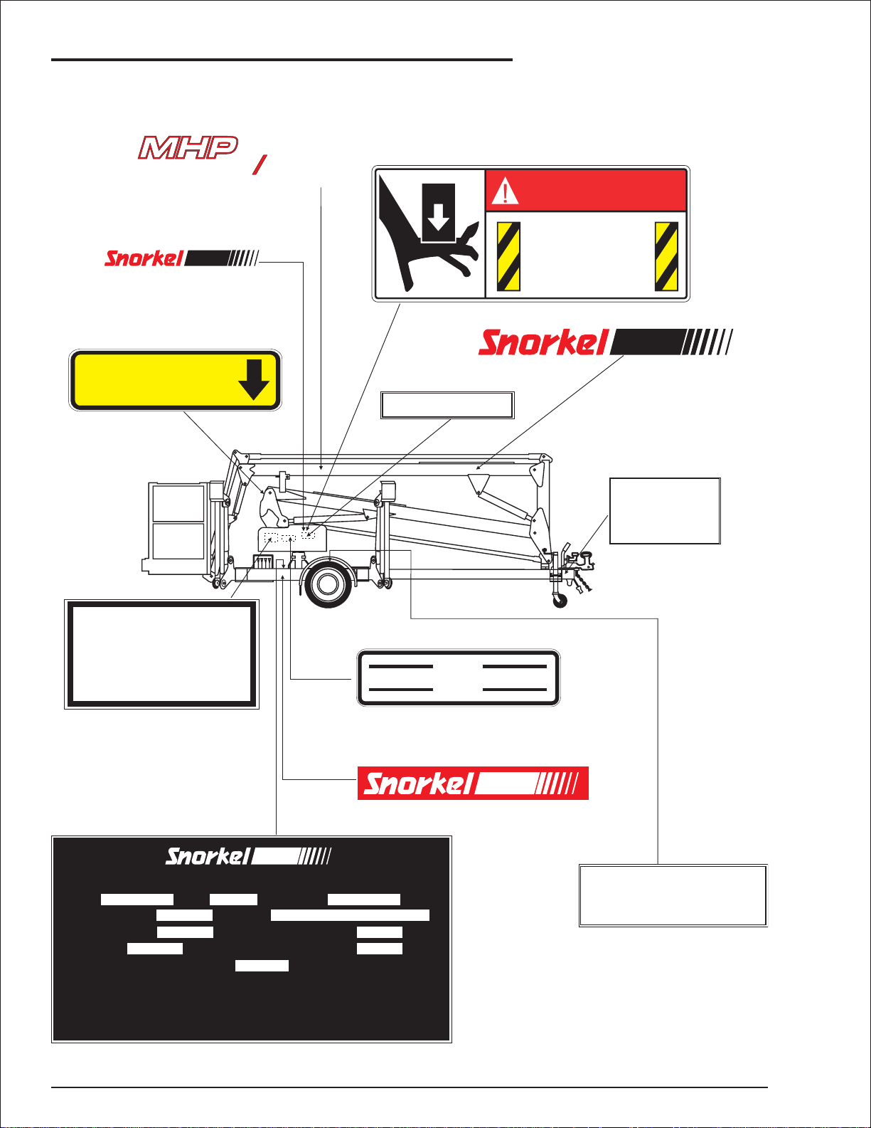
Safety Decals and Placards
There are several safety decals and placards on
the MHP12/34J. Their locations and descriptions
areshowninthissection.Taketime to studythem.
CAUTION
Be sure that all the safety decals and
placards on the MHP12/34J are legible.
Clean or replace them if you cannot read the
wordsor see the pictures.Clean with soap &
water and a soft cloth. Do not use solvents.
You MUST replace a decal or placard if it is
damaged, missing, or cannot be read. If it is
on a part that is replaced, make sure a new
decal or placard is installed on the replaced
MHP12/34J – 11447A page 1 - 3
Page 12
1. Safety
■
Safety Placards and Decals Location
1
234J
10817-4
11227-34
DANGER
PINCH POINT
Keep hands
clear.
302559
EMERGENCY BLEED
DOWN VALVE
0070420
FLUID
HYDRAULIC
CHECK FLUID LEVEL WITH PLATFORM LOWERED
USE PREMIUM HYDRAULIC OIL
GRADE 10W40
VISCOSITY AT 100 F (38 C)
320 SUS (SAYBOLT)
POUR POINT: -35 F (-37 C)
DO NOT OVERFILL
LEVEL
OO
OO
45177-6
HYDRAULIC OIL
FULL
ADD
560239
9207
kmh
SPEED
MAXIMUM
7855
TOWING
80
302950
10812-2
THIS TRAILOR WAS MANUFACTURED TO COMPLY WITH THE INDICATED DESIGN CODES
MODEL
MHP
DATE OF MANUFACTURE
GROSS TRAILER MASS
TYRE SIZE
RECOMMENDED COLD INFLATION PRESSURE
THE TYRES FITTED TO THIS VEHICLE SHALL HAVE A SPEED CATEGORY NOT LESS THAN “L” (120 KWH)
THE SUM OF THE LOAD CARRYING CAPACITIES OF THE TYRES FITTED TO ANY AXLE OR AXLE GROUP OF THIS
VEHICLE SHALL NOT BE LESS THAN THE RELEVANT LOAD SHOWN ABOVE
36 BRUCE RD LEVIN NEW ZEALAND
165 SR 13
S.W.L.
SERIAL NUMBER
VIN NUMBER
AXLE LOAD CAPACITY
310 KPA
RIM SIZE
1250 KG
5X13
DESIGN CODES EN 280
AS 141B.10
TYRE
45
9999
PRESSURE
p.s.i.
310
kPa
COLD
7856-45
page 1 - 4 MHP12/34J – 11447A
Page 13
1
234J
11227-34
OPERATORS CHECKLIST
INSPECT AND/OR TEST THE FOLLOWING DAILY
OR AT THE BEGINNING OF EACH SHIFT
1. OPERATING AND EMERGENCY CONTROLS.
2. SAFETY DEVICES.
3. PERSONAL PROTECTIVE DEVICES.
4. HOSES, FITTINGS AND VALVES FOR LEAKS.
5. CABLES AND WIRING HARNESS.
6. LOOSE OR MISSING PARTS.
7. TYRES AND WHEELS.
8. PLACARDS, WARNINGS, CONTROL MARKINGS
AND OPERATING MANUAL(S).
9. GUARDRAIL SYSTEM.
10.OIL LEVELS.
11.BATTERY FLUID LEVEL.
300699
1. Safety
560239
FIT BOOM CRADLE LOCK PIN
FOR TRAVELLING.
1772-002K
GASOLINE
0071925
Death or serious injury could occur from tipover.
All outriggers must be extended onto firm level surface
before elevating or before entering platform.
Do not exceed platform capacity.
DANGER
EXPLOSIVE FUMES
Death or serious injury might result
from fire or explosion.
Do not smoke or permit open
flames while fueling or near
fueling operations.
Clean up spilled fuel
immediately.
WARNING
0130025
DANGER
YOU MUST NOT OPERATE THIS DEVICE UNLESS:
1.
YOU HAVEBEEN TRAINED IN THE SAFEOPERATION OF THIS
DEVICE AND HHHH
2.
YOU KNOW AND FOLLOW THE SAFETY AND OPERATING
RECOMMENDATIONSCONTAINED IN THE MANUFACTURER'S
MANUALS, YOUR EMPLOYER'S WORK RULES, AND APPLICABLE GOVERNMENTAL REGULATIONS. HHHHHHHH
AN UNTRAINED OPERATOR SUBJECTSHIMSELF AND OTHERS TO
476706
DEATH OR SERIOUS INJURY.
0323897
DANGER
TYRE
45
p.s.i.
PRESSURE
310
kPa
COLD
7856-45
302559
PINCH POINT
Keep hands
clear.
DANGER
PINCH POINT
Keep hands
302559
MHP12/34J – 11447A page 1 - 5
clear.
Page 14
1. Safety
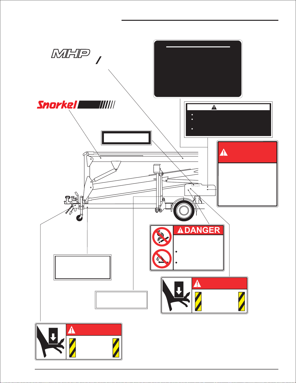
DANGER
LOWER
BOOM
BOOMS
STABILISER
PLATFORM
ELECTROCUTION
HAZARD
THIS MACHINE IS NOT
ELECTRICALLY INSULATED.
Death or serious injury can result from
contact or inadequate clearance to
electrical power lines and apparatus.
Maintain 10 feet minimum clearance
from electrical power lines and
apparatus.
Allow for sway, rock, and sag.
FIT BOOM CRADLE LOCK PIN
FOR TRAVELLING.
KEEP CLEAR OF DESCENDING BOOM
DEATH OR SERIOUS INJURY CAN
OCCUR FROM DESCENDING BOOM
1772-002K
0150602
0323899
UPPER
BOOM
JIB
BOOM
LIFT
ENABLE
11420
SLEW
SPEED CONTROL
ALL FOUR
STABLIZERS
BASE
CHOKE
DANGER
DO NOT ALTER OR DISABLE
LIMIT SWITCHES, SAFETY
SWITCHES, OR INTERLOCKS.
451986
ALL FOUR
STABLIZERS
DANGER
10817-2
2
4
1
3
2
1
4
3
10968-1
KEEP CLEAR OF DESCENDING BOOM
DEATH OR SERIOUS INJURY CAN
OCCUR FROM DESCENDING BOOM
V.I.N.
8945
page 1 - 6 MHP12/34J – 11447A
DO NOT ALTER OR DISABLE
LIMIT SWITCHES, SAFETY
SWITCHES, OR INTERLOCKS.
ALL FOUR
STABLIZERS
0150602
451986
Page 15
LOWER
BOOM
UPPER
BOOM
EMERGENCY LOWER
TO LOWER PLATFORM, OPERATE EMERGENCY
1.
LOWER SWITCH.
TO SLEW BOOM, OPERATE ‘EMERGENCY
2.
LOWER’ & ‘SLEW’ SWITCHES TOGETHER.
1. Safety
EMERGENCY
ROTATE
PLATFORM
LOWER
SWL
200
KG
2025-200
JIB
BOOM
SLEW
LIFT
ENABLE
11420 - 1
SPEED CONTROL
DANGER
BEWARE OF ELECTRICAL HAZARDS
(a) Minimum approach of an appliance
to live electrical apparatus.
(b) Inspection of the work site for
electrical hazards before
commencing to use the appliance.
(c) Constant vigilance and an observer required
whilst working or travelling the appliance
in the vicinity of live electrical apparatus.
REGULATION 133A OF THE
CONSTRUCTION SAFETY ACT 1912 REQUIRES
3m. for voltages up to 132,000
6m. for voltages above 132,000
and up to 330,000
8m. for voltages above 330,000
CHOKE
(Australia Only)
WARNING
KEEP LINESCLEAR POWEROF
CAUTION
Unless the Electrical Supply Authority has advised
the clearance between any live overhead
power line and any part of this machine or
in writing otherwise;
load carried is required to beby law
AT LEAST 4 METRES
This is a requirement of regulation 93 of the
Electrical Supply Regulations 1984
in the interests of safe working.
SAFETY BELTS WITH
SHOULDER STRAPS OR
(New Zealand Only)
SAFETY HARNESS ARE
TO BE USED
MHP12/34J – 11447A page 1 - 7
9928
Page 16

1. Safety
page 1 - 8 MHP12/34J – 11447A
Page 17
2. Safety Devices
■
Safety Device Information
Foremergencyoperation controls andprocedures,
see the “Emergency Operation” chapter 9, in this
manual.
The devices listed in this chapter are safety de
vices.
They are on the MHP12/34J to increase safety in
the workplace forboth the operatorand other peo
ple near the MHP12/34J.
CAUTION
DO NOT by pass, disable, modify, or ignore
anyofthesedevices.Checkthem carefully at
the start of each work shift to see that they
are in working order (see “Daily Inspection
and Maintenance”chapter 7). If any is found
to be defective, remove the MHP12/34J from
service immediately until a qualified service
technician can make repairs.
■
Emergency Stop Switches
At platform control box
❑
-
-
Figure 2.2 - Emergency Stop Switch at
Platform Control Box
At ground control box
❑
Figure 2.1 - Emergency Stop Switch at
Ground Control Box
PresstheEMERGENCY STOPswitchcoverdown,
at any time, under any conditions and the entire
machine stops, and nothing moves. This emergency stop switch covermust be up and the switch
turnedonforanythingontheMHP12/34Jtowork.
NOTE:
The ground control box is designed to override
the platform control box. If the platform control
box EMERGENCY STOP switch is down (off) the
ground control box can still be used to start and
operate the MHP12/34J.
■
Other Safety Devices
❑
Lanyard anchor points
PresstheEMERGENCY STOPswitchcoverdown,
at any time, under any conditions and the entire
machine stops, and nothing moves. This emer
gency stop switch covermust be up and the switch
turnedonforanythingontheMHP12/34Jtowork.
MHP12/34J – 11447A page 2 - 1
-
Figure 2.3 - Lanyard Anchor Points
Page 18
2. Safety Devices
Allpersonnel on theplatformshould attachtheirfall
restraint lanyards to one of the lanyard anchor
points.
Gravity gate
❑
Figure 2.4 - Gravity Gate
The gravitygate is the place in the platform guardrail system where you should enter and leave the
platform.Raise the gate and step under it onto the
platform. Once you have entered the platform and
attached your fall restraint lanyard to an anchor
point, check to see that the gravity gate has fallen
back into place.
Foot switch
❑
Figure 2.6 - Foot Switch
Thefootswitchpreventstheplatformfrommovingif
something accidentally pushes one of the plat
form-moving controls on the platform control box.
Steppingonthefootswitchisanactionthatmustbe
performed, at the same time as another action, to
make the platform move.
Bubble level
❑
-
❑
Guardrails
Figure 2.5 - Guardrails
The guardrails help protect you from falling off the
platform. Be sure the guardrails are properly in
stalled and that the gravity gateor swinging gate is
in place.
Figure 2.7 - Bubble Level
A bubblelevel is located on the trailer side rail, be
side the outrigger controls. Watch the bubble level
while you set the outriggers. Lower the outriggers,
one at a time, just enough to center the bubble in
the circle on top of the guage. When the bubble is
centered the platform is level and can be safely
raised.
-
-
page 2 - 2 MHP12/34J – 11447A
Page 19
RCD/ELCB AC outlet
❑
RCD
Power Outlet
At Platform
Power Input
Connector
Figure 2.8 - RCD/ELCB AC Outlet
The RCD (Residual Current Device) is located at
the base and will protect against short circuits to
earth. When there is a short circuit the RCD will
shutdownthe230vACpowertotheplatformoutlet.
2. Safety Devices
To reset the outlet disconnect the power tool lead
from the platform box and reset the RCD at the
base.
If the problempersists call atrained service technician.
❑
Flashing light
Figure 2.9 - Flashing Light
The flashing light alerts people that the
MHP12/34J is moving. The light flashes at about
one flash per second any time the MASTER KEY
switch is on. There is no ON/OFF switch for the
flashing light, it cannot be turned off while the
MHP12/34J is running.
MHP12/34J – 11447A page 2 - 3
Page 20

2. Safety Devices
page 2 - 4 MHP12/34J – 11447A
Page 21

3. Specifications
The Snorkelift MHP12/34J is a boom supported elevating wor k platform built to conform to all applicable
OSHA, ANSI or CSA standards as previously outlined.
OSHA Paragraph 1910.67 Title 29, C.F.R.,Vehicle-MountedElevating and Rotating Work Platforms - La
bour.
OSHA Paragraph 1926.556 Title 29, C.F.R., Aerial Lifts - Construction.
Australian Standard AS1418-10 1996 Elevating Work Platforms.
■
General Specifications
SPECIFICATIONS MHP12/34J
Nominal working height
Maximum height to basket floor
Maximum outreach
Maximum outreach height
Maximum width of base
Outriggers retracted
Outriggers extended
Safe working load (unrestricted)
12.4m 40’8”
10.4m 34’1”
5.4m 17’9”
5.65m 18’6”
1.55m
3.50m
200kg 440lbs
5’1”
11’5”
-
Standard colour Orange base/boom grey platform
Platform size
Travelling height
Overall length
Maximum towing speed
Turntable rotation
Trailer tongue weight
Maximum rated axle capacity
Insulation rating
Weight
1200 x 760 x 1100mm
Aluminum
2.04m 6’8”
5.71m 18’8”
80km/h 50m/h
550 degrees non-continuous
75kg 165lbs
1200kg 2645lbs
Nil
1160kg 2609lbs
4’x 2’ 6” x 3’ 7”
Aluminum
MHP12/34J – 11447A page 3 - 1
Page 22

3. Specifications
■
Engine Data
Engine Make Honda (gasoline)
Model GX 160
Engine type 4-stroke, over head valve, 1 cylinder
Displacement 163 cm3(9.9 cu-in)
Bore x Stroke 68 x 45 mm (2.7 x 1.8 in)
Max. output 4 kW/4,000 rpm
Max. torque 1.1 kg-m (8.0 ft-lb)/ 2500 rpm
Fuel gasoline
Fuel Grade automotive gasoline (unleaded or lowleaded preferred)
Fuel consumption 230 g/PSh
Cooling system Forced air
Ignition system Transistor magneto
PTO shaft
rotation
Oil Capacity 0.60 litres (0.60 US qt, 0.53 Imp qt)
Oil Grade SAE 10W-30
Counterclockwise
page 3 - 2 MHP12/34J – 11447A
Page 23

3. Specifications
(
)
(
)
■
Overall Dimensions - MPH12/34J
6’ 8”
20”
525mm
2040mm
(16.5”)
420mm
35mm
(1.3”)
3370mm
5710mm
(18’ 8”)
1550mm
(5’ 1”)
MHP12/34J – 11447A page 3 - 3
Page 24

3. Specifications
S
FEET
■
Working Envelope - MHP12/34J
15
14
METER
13
12
50
45
40
11
35
10
9
30
8
25
7
6
5
4
3
2
1
METERS
0
6
METERS
20
15
10
5
FEET
0
5
4
3
2
1
0
1
2
3
4
5
6
20
FEET
page 3 - 4 MHP12/34J – 11447A
15
10
5
0
5
10
15
20
Page 25

■
Nomenclature And Serial Numbers
Right side view of machine
❑
3. Specifications
Jockey
wheel
To w
coupling
Draw bar
Engine
cover
Outriggers (4)
Column
Trailer
Ground
controls
Outrigger
controls
Platform
controls
Platform
❑
Booms identification
Levelling
turret
Lower
boom
Upper boom
Jib
boom
VIN Number
MHP12/34J – 11447A page 3 - 5
Page 26

3. Specifications
Left side view of machine
❑
Jib Cylinder
Upper
cylinder
Lower cylinder
Hand
brake
Oil tank
cover
❑
Serial number location, chassis
Outrigger cylinder
Serial number
plate
page 3 - 6 MHP12/34J – 11447A
Page 27

4. Gauges
■
Hourmeter
Figure 4.1 - Hourmeter
The hour meter is basically an electric clock. It ac
cumulates time when the master key switch is
turnedon.The hourmetercannotbereset.AnMHP
qualifiedservicetechnician canuse itto tellwhen it
is time for the periodic maintenance listed in the
maintenance manual.
■
Hydraulic Oil Level
Figure 4.3 - Hydraulic Oil Level
Thehydraulicoil levelguageis on thesideofthehy
-
draulicoil tank.It showsthe actuallevelof oilinside
thetank.Readit onlywhen thebooms are fullylow
eredandoutriggers areraisedinthe travelposition.
Theoillevelshouldbe within +or -6mm (1/4”)of the
line.
-
-
■
Level Bubble
Figure 4.2 - Level Bubble
A level bubble is located beside the outrigger con
trol valve, mounted on the trailer base. Watch the
bubblewhile you set the outriggers.Lower the out
riggers,front onesfirst,one atatime justenough to
center the bubble in the circle on top of the guage.
When the bubbleis centralthe platform is leveland
the platform can be safely raised.
-
-
MHP12/34J – 11447A page 4 - 1
Page 28

4. Gauges
page 4 - 2 MHP12/34J – 11447A
Page 29

5. Automatic Shut-offs and Circuit Breakers
■
RCD/ELCB Outlet (option)
Figure 5.1 - RED/ELCB Outlet
The RCD (Residual Current Device) is located at
the base and will protect against short circuits to
earth. When there is a short circuit the RCD will
shutdownthe230vACpowertotheplatformoutlet.
To reset the outlet disconnect the power tool lead
from the platform box and reset the RCD at the
base.
■
Outriggers
Figure 5.3 - Outriggers
The MHP12/34J cannot beraised unless the outrig
gersareloweredand theliftenablelighton thelower
controlboxislit.Oncethe boomsareraisedfrom the
stowedposition theoutriggers become disabledun
til the booms are stowed in the travel position.
-
-
If the problempersists call atrained service technician.
■
Main Circuit Breaker
Figure 5.2 - Main Circuit Breaker
There is only one circuit breaker, on a standard
MHP12/34J, that is accessible to the operator. Its
purpose is to protect the electrical circuits from
electrical overloads.When the circuit breaker trips
(pops out) push it back in then attempt to use the
MHP12/34J. If the circuit breaker trips a second
time, take the MHP12/34J out of service and refer
the problem to a qualified trained service techni
cian for repair.
-
MHP12/34J – 11447A page 5 - 1
Page 30

5. Automatic Shut-offs and Circuit Breakers
page 5 - 2 MHP12/34J – 11447A
Page 31

■
Controls Description
This chapter explains what each control does.
This chapter DOES NOT explain how to use the
controls to produce useful work, refer to the “Oper
ation” chapter 8-1 for that after you have read this
chapter.
For optional equipment controls, see the “Options”
chapter.11-1
Seethe “Emergency Operation”chapter 9-1 for the
location of the emergency bleed down control and
for correct emergency bleed down procedures.
Controls and Control Decals Locations
❑
BOOMS
LOWER
BOOM
STABILISER
PLATFORM
6. Controls
ThemainoperatingfunctionsofanMHP12/34Jcan
be controlled from the ground control box or from
the platform control box.
-
UPPER
BOOM
JIB
BOOM
LIFT
ENABLE
11420
SLEW
SPEED CONTROL
Ground Controls
BASE
CHOKE
Platform Controls
LOWER
BOOM
UPPER
BOOM
EMERGENCY LOWER
TOLOWER PLATFORM, OPERATE EMERGENCY
1.
LOWER SWITCH.
TO SLEW BOOM, OPERATE‘EMERGENCY
2.
LOWER’ & ‘SLEW’ SWITCHES TOGETHER.
ROTATE
PLATFORM
EMERGENCY
LOWER
JIB
BOOM
LIFT
ENABLE
11420- 1
SLEW
SPEED CONTROL
CHOKE
MHP12/34J – 11447A page 6 - 1
Page 32

6. Controls
■
Ground Control Box
Controls for operating the MHP12/34J from the
ground, are located on the right side of the turnta
ble.
NOTE
The number of each control below corresponds to
the control’s call out on the control box illustration.
1.
Emergency Stop: Press the EMERGENCY
STOP switch cover down, at any time, under
any conditions, and the entire machine stops,
and nothing moves. This emergency stop
switch cover must be up and the switch
turned on for anything on the MHP12/34J to
work.
2.
Platform/Ground Selector : Must be in the
GROUND position (down) for the ground
control box to work. The switch MUST be in
the PLATFORM position (up) for the platform
control box to work.
3.
Choke/Cold Start: Hold the switch UP while
you start an engine that is at ambient air
temperature (a "cold" engine). This will choke
the engine.
4.
Master Key Switch: This switch works like
an automobile ignition switch. Hold it at
START until the engine starts, then release it
to ON. (-) Turn the Master Key Switch to
OFF (O) if the platform is to stay in one
position for a long time, that will turn the
engine off and save fuel.
5.
Boom Speed: This control determines how
fast the booms move.Set it to SLOW (turtle)
until you are very familiar with the way the
machine works or if the platform is working in
dangerous or cramped surroundings.
6.
Stablizer / Boom Selector Switch:
Must be in Stablizer (outrigger) position
(down) for the outriggers to wor k. Once
outriggers are down and set the switch must
be placed in the boom (up) position for the
booms to work.
Control switches 7 through 10 are the platform
movingswitches.Each isa three position,momen
tary contact, normally OFF switch.
9.
Jib Boom: UP raises the jib boom. DOWN
lowers the jib boom.
10.
-
-
Slew: LEFT rotates the entire turntable and
boom to the left. RIGHT rotates the entire
turntable and boom to the right.
11.
Lift Enable: The platform can only be raised
when this light is lit. When this light is not lit
the platform will not raise because the
outriggers are not proper ly set.
NOTE
(See “Nomenclature and Serial Numbers” in the
“Specifications” chapter 3, for boom
identification.)
7.
Lower Boom : UP raises the lower boom.
DOWN lowers the lower boom.
8.
Upper Boom: UP raises the upper boom.
DOWN lowers the upper boom.
page 6 - 2 MHP12/34J – 11447A
Page 33

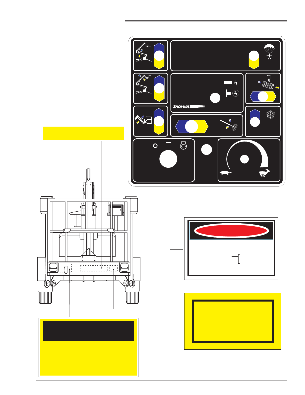
Ground Control Box Controls
❑
6. Controls
1
BOOMS
7
6
LOWER
BOOM
8
STABILISER
PLATFORM
2
UPPER
BOOM
9
JIB
BOOM
4
SLEW
LIFT
BASE
3
CHOKE
5
ENABLE
11420
10 11
MHP12/34J – 11447A page 6 - 3
SPEED CONTROL
Page 34

6. Controls
■
Platform Control Box
Controls for operating the MHP12/34J from the
platform are located on the platform control box,
with the exception of the footswitch which is on the
platform floor.
NOTE
The number of each control below corresponds to
the control’s call out on the control box illustration.
1.
Emergency Stop: Press the EMERGENCY
STOP switch cover down, at any time, under
any conditions, and the entire machine stops,
and nothing moves. This emergency stop
switch cover must be up and the switch
turned on for anything on the MHP12/34J to
work.
2.
Choke/Cold Start: Hold the switch UP while
you start an engine that is at ambient air
temperature (a "cold" engine). This will choke
the engine.
3.
Anti-Restart: This switch works like an
automobile ignition switch.Hold it at START
until the engine starts, then release it to ON
(-). If the engine dies in ON, the key must be
turned to OFF (O) before it will go back to
START. Turn the switch to OFF if the platform
is to stay in one position for a long time, that
will tur n the engine off and save fuel.
4.
Boom Speed: This control determines how
fast the booms move.Set it to SLOW (turtle)
until you are very familiar with the way the
machine works or if the platform is working in
dangerous or cramped surroundings.
5.
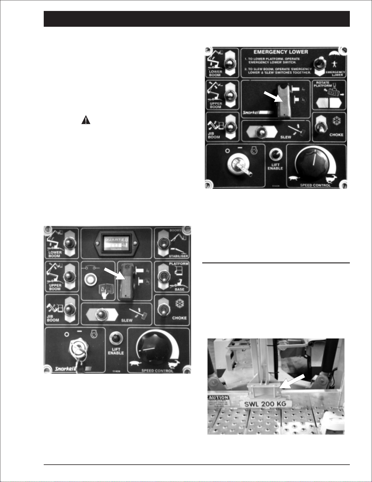
Emergency Lower: If the engine stops and
cannot be restarted, hold the switch down
and this will lower the upper and lower
booms (not the jib boom). To slew during
emergency lower operate emergency lower
and slew switches together.
8.
Upper Boom: UP raises the upper boom.
DOWN lowers the upper boom.
9.
Jib Boom: UP raises the jib boom. DOWN
lowers the jib boom.
10.
Slew: LEFT rotates the entire turntable and
boom to the left. RIGHT rotates the entire
turntable and boom to the right.
11
Lift Enable: The platform can only be raised
when this light is lit. When this light is not lit
the platform will not raise because the
outriggers are not proper ly set.
12.
Foot Switch: You must step down on the foot
switch, and hold it down when you use any
platform control that causes the platform to
move.
Items 6 through 10 are the platform moving
switches.Each isa threeposition, momentary con
tact, normally OFF switch.
NOTE
(See “Nomenclature and Serial Numbers” in the
“Specifications” chapter 3, for boom
identification.)
6.
Platform Rotate: (Option) LEFT rotates the
platform left. RIGHT rotates the platform
right.
7.
Lower Boom: UP raises the lower boom.
DOWN lowers the lower boom.
page 6 - 4 MHP12/34J – 11447A
-
Page 35

Platform Control Box Controls
❑
6. Controls
10
1
EMERGENCY LOWER
TO LOWER PLATFORM, OPERATE EMERGENCY
1.
7
LOWER
BOOM
8
UPPER
BOOM
9
JIB
BOOM
LOWER SWITCH.
TO SLEW BOOM, OPERATE ‘EMERGENCY
2.
LOWER’ & ‘SLEW’ SWITCHES TOGETHER.
SLEW
RO TATE
PLATFORM
EMERGENCY
LOWER
CHOKE
5
6
2
11
3
LIFT
4
ENABLE
11420 - 1
SPEED CONTROL
12
MHP12/34J – 11447A page 6 - 5
Page 36

6. Controls
page 6 - 6 MHP12/34J – 11447A
Page 37

7. Daily Inspection and Maintenance
At the start of each work day (or 8 hour shift), an
MHP12/34J qualified operator must perform the
Daily Inspection and Maintenance as listed in the
table below.
The purpose of the Daily Inspection and Mainte
nance isto keep the MHP12/34Jin proper working
condition and to detect signs of malfunction at the
earliest possible time.
The MHP12/34J should be in the STOWED
POSITION and the Master KeySwitch set to OFF
before you begin this inspection.
■
Daily Inspection and Maintenance Table
Item Service Required
Engine fuel level Look to see that the fuel tank is full
Fuel tank cap Check to see that the cap is tight
Engine oil level Check oil level (between dipstick lines)
Fuel leaks Visually inspect (hoses and connections)
Engine coolant Check that grills are not blocked
Wiring harnesses Visually inspect (installation, condition)
Battery terminals Visually inspect (no corrosion)
Battery fluid level Check fluid level (1/4" or 6 mm below filler neck)
Hydraulic oil level Visually inspect level (between lines on gauge)
Hydraulic oil leaks Visually inspect (hoses, tubes)
Tires and wheels Visually inspect (condition)
Bolts and fasteners Visually inspect (condition)
Structural damage and welds Visually inspect (weld cracks, dents)
Lanyard anchor points Visually inspect (condition)
Platform gravity gate Check condition and operation
Platform guardrails Visually inspect (condition)
Flashing light (option) Visually inspect (operation)
Ground control switches Actuate and inspect for proper operation
Level sensor (option) Check operation
Emergency lower Check operation (causes correct motion)
Platform control box switches Actuate and inspect for proper operation
RCD/ELCB AC outlet (option) Check operation
Platform work lights (option) Check operation
Placards and decals Visually inspect (installation, condition)
Defective par ts and/or equipment malfunctions
jeopardizethe safetyof theoperator andother per
sonnel, and can cause damage to the machine.
-
DONOToperatean MHP12/34J that isknown
to be damaged or malfunctioning.
Repair all equipment damage or
malfunctions,before placing the MHP12/34J
into service.
DANGER
-
MHP12/34J – 11447A page 7 - 1
Page 38

7. Daily Inspection and Maintenance
Therest of thischapter shows howtoperformthe in
spection and maintenance required for each item in
the Daily Inspection and Maintenance Table.
■
Engine Fuel Level
Figure 7.1 - Engine Fuel Level
Visually check to see that the gasoline tank is full.
See the “Specifications” chapter 3, fuel for octane
and grade.
■
Fuel Tank Cap
Visually inspect the Honda fuel tank and the entire
length of the fuel line, from the engine to the fuel
tank, for leaks.
■
Engine Oil Level
COMBINED OIL FILLER
CAP AND DIPSTICK
OIL LEVEL FILLED TO
TOP OF FILLER NECK
OIL LEVEL
Figure 7.4 - Engine Oil Level
Remove the oil filler cap and wipe the dipstick
clean. Insert the dipstick into the oil filler neck, but
do not screw it in.
If the level is low, fill to the top of the oil filler neck
with the recommended oil.
See the “Specifications” chapter 3, for the correct
engine oil grade and weight.
Figure 7.2 - Fuel Tank Cap
Check to see that the tank cap is in place and is
tight.
■
Fuel Leaks
■
Wiring Harnesses
Figure 7.5 - Wiring Harnesses
Figure 7.6 - Wiring Harnesses
Inspect all the wiring harnesses, on the machine,
for loose connections, broken wires, and frayedin
Figure 7.3 - Fuel Leaks
page 7 - 2 MHP12/34J – 11447A
sulation.
-
Page 39

■
Battery Terminals
Figure 7.7 - Battery Terminals
Battery terminals should be tight, clean and free of
dirt and corrosion.
■
Battery Fluid Level
7. Daily Inspection and Maintenance
Figure 7.9 - Hydraulic Oil Level
The hydraulic oil level should be between the two
marks on the decal.
DANGER
Batteries emit hydrogen and oxygen,
elements that can combine explosively.
DO NOT smoke or permit open flames or
sparks when checking batteries.
Figure 7.8 - Battery Fluid Level
Remove the caps from the battery and visually
checkto seethat thebattery fluidis 1/4”(6 mm) be
low the bottom of the filler neck inside each hole.
Figure 7.10 - Hydraulic Oil Filler Cap
If necessary, add hydraulic oil at the filler cap.See
the“Specifications”chapter 3,fortype and gradeof
hydraulic oil.
■
Hydraulic Oil Leaks
DANGER
Leaking hydraulic oil can cause burns, fires,
falls (slipping), cuts, and puncture wounds
(if under high pressure).Do not search for
leaks with your hand. Have a qualified
trained maintenance person repair all
hydraulic fluid leaks before you operate an
MHP12/34J.
-
■
Hydraulic Oil Level
To check the hydraulic oil level:
Completely lowerthe booms and ensure the stabi
lizers are in the stowed position.
MHP12/34J – 11447A page 7 - 3
-
Figure 7.11 - Hydraulic Oil Leaks
Page 40

7. Daily Inspection and Maintenance
Hydraulic oil leaks are easily visible and can show
up anyplace.
Visuallyinspect theentire machine forhydraulicoil.
Checkthe groundunderthemachine forleakedoil.
Carefully inspect the ends of the upper and lower
booms. Oil can run down inside of the booms and
drip out the end.
■
Bolts and Fasteners
Visually inspect all fasteners to see that none is
missing or obviously loose.
Figure 7.14 - Tyre Condition
Check each wheel for obvious damage that could
cause a blowout.
Figure 7.12 - Critical Pin Retainer Bolts
Critical pin retainer bolts have locktab washers fitted, theyshould allbe presentand not damaged in
any way.
Figure 7.13 - Wheel Nuts
Pay particular attention to all of the wheel nutsand
bolts.
None should be visibly loose, missing, or de
formed.
Figure 7.15 - Location of Tyre Pressure Decal
Ensuretyre pressures aremaintained accordingto
the decal attached to the chassis behind the mud
guard (fender).
■
Structural Damage and Welds
Visually inspect all welds for cracks, all structural
members for deformity.
-
-
■
Wheels and Tyres
TheMHP12/34J relies onit’styresfortowing stabil
ity.
page 7 - 4 MHP12/34J – 11447A
-
Figure 7.16 - Chassis Welds
Page 41

7. Daily Inspection and Maintenance
Pay particular attention to the chassis welds
Figures 7.17 - Boom Welds
Closely inspect boom welds all the way around, for
cracks.
■
Lanyard Anchor Points
■
Platform Guardrails
Figure 7.20 - Platform Guardrails
Visually inspect the platform guardrails to see that
none of the tubing has been cut out, removed, or
deformed in any way.
Visually checkthe guardrail welds to see thatnone
is cracked nor ground down.
■
Flashing Light (option)
Figure 7.18 - Lanyard Anchor Points
Visuallycheckthelanyardanchor points toseethat
they are not deformed or cut off.
■
Platform Gravity Gate
Figure 7.19 - Platform Gravity Gate
Figure 7.21 - Flashing Light
Visuallychecktheoptionalflashinglight,to see that
thelightflashes atapproximatelyoneflashper sec
ond when the motor key switch is turned on.
-
MHP12/34J – 11447A page 7 - 5
Page 42

7. Daily Inspection and Maintenance
■
Ground Control Switches
Figure 7.22 - Ground Control Switches
With the Ground/Platform Selector set to
ground:
Check that each of the platform moving switches
( through to ) cause the MHP12/34J to move
the way it should.
Check both positions of each switch.
For correct operating procedures see the “Opera-
tion” chapter 8.
NOTE
Pay particular attention to the Emergency Stop
switch to see that it tur ns the MHP12/34J
engine off when the red cover is struck.
With the booms raised open the Emergency
Lower Valve on the top of the manifold valve.
Theboomsshouldbegintolower.Therateoflower
ing can be regulated by the amount the valve is
opened.
To check the slew function when using the manual
emergency lower valve the Master Key Switch
and Emergency Stop switch must be on and the
Platform/groundSelector mustbesettoground.
To slew(withthemanual emergency lowervalveal
ready open) select the required direction on the
slew toggle switch .
NOTE
The manual emergency lower valve must be
closed after the test to ensure proper boom
operation.
For correct emergency lowering operating proce
dures see “Emergency Operation” chapter 9.
Upper control box
❑
Emergency lower from the upper control box is
achievedbyturning the uppercontrol to onand depressing thefoot switchwhilst operatingthe Emer-
gency Lower switch
To slew the unit select thedirection required on the
slew toggle switch at the same time. For correct
emergency lowering operating procedures see
“Emergency Operation” chapter 9.
■
Platform Control Switches
-
-
-
■
Emergency Lower
❑
Lower control box
Figure 7.23 - Emergency Lower Valve
page 7 - 6 MHP12/34J – 11447A
Figure 7.24 - Platform Control Switches
Page 43

7. Daily Inspection and Maintenance
On the ground control box set the Ground/Plat
form Selector to platform.
Check that each of the platform moving switches
( through to ) cause the platform to move the
way it should.
Check both positions of each switch.
For correct operating procedures see the ”Opera
tion” chapter 8.
NOTE
Pay particular attention to the Emergency Stop
switch to see that it turns the MHP12/34J
engine off when struck.
Pay particular attention to the platform foot switch
to see that it deactivates the platform moving
switches when the foot switch is not stepped on.
■
AC Outlet RCD/ELCB (option)
-
Standard placards and decals
❑
Seepage7-8forthefollowing items.
No Part No Description Req
-
9999 Serial number plate
1
451776 Decal - Hydraulic fluid level
2
108172 Decal - Snorkel
3
302950 Decal - Hydraulic oil level
4
7856-45 Decal - Tyre pressure
5
7855 Decal - Towing speed
6
9207 Decal - Hydraulic oil
7
0070420 Decal - Emergency lower
8
560239 Decal - Snorkel
9
302559 Decal - Pinch point
10
10817-4 Decal - Snorkel
11
1
1
2
1
2
1
1
1
2
2
2
Figure 7.25 - AC Outlet RCD/ELCB
If the MHP12/34J has this option fitted check the
RCD works by connecting a power source to the
base inlet and an appliance to the platform outlet.
Push the test button on the RCD/ELCB device and
the power outlet at the platform should not work.
CAUTION
RCD/ELCB devices should only be replaced
by a qualified electrician.
■
Placards and Decals
Looktoseethat all placardsanddecalsarein place
and legible. Replace any missing or illegible plac
ardsordecalsbeforeplacingtheSnorkeliftinto ser
vice for the daily work shift.
Decalandplacard kitsfortheMHP12/34Jare avail
able from Snorkel dealers.
11227-34 Decal - MHP12/34J
12
007-1925 Decal - Gasoline
13
300699 Decal - Operator checklist
14
0130025 Decal - Warning
15
0323897 Decal - Danger
16
476706 Decal - Danger explosive gas
17
11420 Decal - Lower control box
18
0323899 Decal - Electrocution hazard
19
0150602 Decal - Descending boom
20
451986 Decal - Limit switches
21
9223-3 Decal - Chevron
22
10968-1 Decal - Outrigger control
23
8945 Decal - Vin plate
24
11420-1 Decal - Upper controls
25
2025-200 Decal - Safe working load
26
99228 Decal - Caution
27
1772-002K Decal - Boom lock pin
28
-
29
-
11287-3 Decal - Chevron
30
-
9428 Decal-Danger(AustraliaOnly)
31
1843 Decal - Warning (NZ Only)
2
1
1
1
1
1
1
1
4
5
4
1
1
1
1
1
2
4
1
1
MHP12/34J – 11447A page 7 - 7
Page 44

7. Daily Inspection and Maintenance
Inspection drawing
❑
11
1
20
12
9
10
28
20
3
7,4,2
9
6
5
(X4), 30 (X4)
22
11
(x4)
21
12
5
21,20
13
25
23
28
28
18
19
8
3
24
10
14,15,16,17
27
26
31
page 7 - 8 MHP12/34J – 11447A
Page 45

■
Operating Procedures
This chapter explains howto properly start andop
erate an MHP12/34J.Read and understand all the
previous chapters in this manual before you begin
to operate an MHP12/34J.
CAUTION
IfyouusetheMHP12/34Jforpaintingbesure
the optional sandblast protection kit is
installed to protect the hydraulic cylinder
rodsfrom paint.Donot leavethe MHP12/34J
enginerunningif youare sandblasting.Sand
drawn into the air intake can erode engine
parts.
■
Control Stations
An MHP12/34J can be operated from the ground
control box or from the platform control box.There
are basically two differencesbetween ground con
troland platformcontroloperations, both aresafety
related:
1. The ground control box can override the
platform control box at any time.If a person
operating the machine from the platform
becomes incapacitated, a person on the
ground can always take over machine control.
2. The outriggers can only be selected from the
ground control box and only when the
booms are in the stowed position.
8. Operation
-
-
Figure 8.1 - Ground Control Box Emergency
Stop Switch Location.
DANGER
TheMHP12/34JisnotElectricallyInsulated.
Death or Serious Injury to operating
personnel, can occur if the machine should
come into contact with energized electrical
wires during operation.
DO NOT attempt to operate the MHP12/34J
ground controls if the platform, booms, or
any other conducting part of an MHP12/34J
is in contact with energized electrical wires
or if there is an immediate danger of such
contact.
NOTE
See the "Electrical Hazard" section, in this
manual for a complete explanation of the hazards
concerning electricity.
■
Emergency Stopping
To stop an MHP12/34J, press the Emergency
Stop switch cover down on either of the two
EMERGENCY STOP switches at the ground con
trol box or at the platform control box.
Figure 8.2 - Platform Control Box Emergency
Stop Switch Location.
NOTE
For a complete discussion of the Emergency
Stop switches, see “Controls” chapter 6, in this
manual.
-
MHP12/34J – 11447A page 8 - 1
Page 46

8. Operation
■
Operation Considerations
To use this chapter, firstdecide whether youwill be
starting and operating the MHP12/34J from the
ground control box or the platform control box.
Beginat thesectionentitled "Starting FromGround
Control Box", if you intend to start and run the
MHP12/34J from the ground station.
Begin at the section entitled "Starting From Plat
form ControlBox", if youintend to start and run the
MHP12/34J from the platform.
■
Starting From Ground Control Box
Before you begin to operate the MHP12/34J from
the ground control box, a qualified operator must
performthe "DailyInspection andMaintenance" as
described in chapter 7, of this manual.
To start the engine from the ground control box do
the following:
1.
Set the Emergency Stop switch to ON
(see Figure 8.3).
5.
Turn the key to Start and hold it there until
the engine starts or for a maximum time of 6
seconds.When the engine starts release the
key and the choke switch , if you used it
(see Figure 8.3).
CAUTION
If the engine does not startin 6 seconds turn
-
the key off and release the choke . Wait 60
seconds before trying to restart the engine
again. Continual cranking of the starter
motor will only result in its damage.
The engine should now be running, and the
MHP12/34J is ready to begin work.
■
Stabilizer Operation
Ensure the boom/stabilizer switch (item on the
ground control box) (see Figure 8.3) is set to stabi
lizer.
Activate the stabilizers with the valve levers ensur
ing thatthe front stabilizers are lowered first to prevent damage to the jockey wheel.
-
-
Figure 8.3
Figure 8.3 - Ground Control Box Starting
2.
Set the Platform/Ground Selector switch
to GROUND (see Figure 8.3).
3.
Insert the key (see Figure 8.3) into the
Master Key Switch and turn the key on.
4. If the engine is at ambient temperature
(cold), hold the Choke / Cold Start Switch
(see Figure 8.3) up throughout the next
step.
Activate the rear stabilizers and level the machine
usingthelevelbubbleadjacent to thecontrol levers.
CAUTION
Ensure all four foot plates are in full contact
with the ground and that they are clear of
manholecovers,drainsand unstable ground
etc.
page 8 - 2 MHP12/34J – 11447A
Page 47

■
Starting From Platform Control Box
Before you begin to operate the MHP12/34J from
the platform control box, a qualified operator must
performthe "DailyInspection andMaintenance" as
described in chapter 7, of this manual.
To start the engine from the platform control box
youmust first setsome switchesonthegroundcon
trol box, including setting the outriggers and level
ing the machine.
(See page 8-2 for information on setting the
stabilizers)
1.
Insert the key into the Master Key Switch
at the ground control box and turn the key on
(see Figure 8.4).
8. Operation
3.
Enter the platform, close the gravity gate ,
and attach the lanyard of your fall restraint
(safety harness) to one of the anchor points
(see Figure 8.5).
-
-
Figure 8.4
2.
Set the Platform/Ground Selector (see
Figure 8.4) at the ground control box to
PLATFORM.
Figure 8.6
4.
Set the Emergency Stop switch to (ON)
(see Figure 8.6).
5.
Turn the Anti-Restart switch to ON (see
Figure 8.6).
6. If the engine is at ambient temperature (cold),
hold the Choke Switch (see Figure 8.6) up
throughout the next step.
7.
Turn the Anti-Restart switch to START
and hold it there until the engine star ts or for
a maximum time of 6 seconds. When the
engine starts, release the key (6) and the
choke switch , if you used it (see Figure
8.6).
CAUTION
Iftheengine does notstart in 6 seconds,turn
the Anti-Restart switch OFF.and release the
choke. Wait 60 seconds before trying to
restart the engine again. Continual cranking
of the starter motor will only result in its
damage.
The engine should now be running, and the
MHP12/34J is ready to begin work.
Figure 8.5
MHP12/34J – 11447A page 8 - 3
Page 48

8. Operation
■
Moving The Platform
The engine should already be running (as de
scribed earlier in this chapter),before youstartthis
section.
DANGER
DO NOT operate near energized electrical
conductors. Maintain the (M.S.A.D.),
Minimum Safe Approach Distance to
energized power lines. See the "Electrical
Hazard" section, in this manual for a
complete explanation of the hazards
concerning electricity. Maintain the
clearances shown on the decal attached to
the platform.
-
UP
1. Lower Boom
LOWER
DOWN
BOOM
Be certain that the space into which you are
about to move the platform,boom,turntable,
and/or chassis is free of obstructions.
ALWAYS look in the direction of movement.
When you operate from the platform control
box, be sure that the lanyard of your fall
restraint is attached to an anchor point on
the platform mount. Also, be sure that
platform gate is closed behind you.
❑
From Ground Control Box
Eachof the waysthe platformcanmoveis shown in
the following photograph and switch illustration:
The photograph shows the platform switches that
cause the platform or booms to move.
These platform moving switches, ( through ),
willproducethe movementas indicated bythe illus
tration's to the right.
UP
2. Upper Boom
UPPER
DOWN
BOOM
UP
3. Jib Boom
JIB
BOOM
DOWN
-
LEFT
RIGHT
SLEW
4. Slew
Figure 8.8 - Ground Control Box Operation
Platform Moving Switch Illustration
Figure 8.7 - Movement Control, Ground
Control Box
page 8 - 4 MHP12/34J – 11447A
Page 49

From Platform Control Box
❑
Whenyouoperatefromthe platform controlbox,be
surethatthelanyardofyourfallrestraintisattached
to an anchor point on the platform mount. Also, be
surethegravitygate is closed.Each of thewaysthe
platform can moveis shown in the following photo
graph and switch illustration:
The photograph shows the platform switches that
cause the platform or booms to move.
These platform moving switches, ( through ),
willproducethe movementas indicated bythe illus
tration's to the right.
8. Operation
UP
1. Lower Boom
-
LOWER
BOOM
-
DOWN
UP
2. Upper Boom
Figure 8.9 - Movement Control, Platform
Control Box
Youmustbe steppingontheplatform footswitch
when you use any of the platform moving switches
( through ) The platform foot switch is a safety
featuretopreventtheplatform frommovingifaplat
form moving switch, or controller, is accidentally
pushed.
UPPER
DOWN
BOOM
UP
3. Jib Boom
JIB
BOOM
LEFT
DOWN
RIGHT
SLEW
4. Slew
-
ROTATE
PLATFORM
5. Platform Rotation
LEFT
RIGHT
Figure 8.11 - Platform Control Box Operation
Platform Moving Switch Illustration
■
Securing for Day
Atthe endofeach workdaythe MHP12/34Jshould
bereturned totheSTOWEDPOSITIONandlocked
as described under “Stowing” in the "Stowing and
Transporting" chapter 10.
Figure 8.10 - Platform Foot Switch
MHP12/34J – 11447A page 8 - 5
Page 50

8. Operation
page 8 - 6 MHP12/34J – 11447A
Page 51

■
Emergency Operation Procedures
The following procedures are emergency proce
duresonly.DONOTuse them fornormal operation.
Their purpose is to get the platform and operator
safelyto groundwhen the MHP12/34J will notstart
orsomeotherproblemkeepstheplatformfromlow
ering in the normal way.
Operation From Platform Control Box
❑
Switchsettings listed in the threesteps belowmust
exist at the ground before emergency operation
procedures will work at the platform control box:
9. Emergency Operation
5.
Set the Anti-Restart switch (see Figure
-
-
9.2) to ON.
Figure 9.3
6.
Step on the platform foot switch (see
Figure 9.3).
Figure 9.1
1.
The Master Key Switch must be ON (see
Figure 9.1).
2.
The Emergency Stop switch must be
(ON) (see Figure 9.1).
3.
The Platform/Ground Selector switch
(see Figure 9.1) must be set to PLATFORM.
Figure 9.2
4.
Set the Emergency Stop switch to ON
(see Figure 9.2).
Figure 9.4
7.
Hold the Emergency Lower switch (see
Figure 9.4) down and the platform will begin
lowering.
NOTE
To slew when using emergency lowering operate
the slew switch in the direction required (see
Figure 9.4).
MHP12/34J – 11447A page 9 - 1
Page 52

9. Emergency Operation
Operation From Ground Control Box
❑
Figure 9.5 - Manual Lower Valve
1. Open manual valve to lower platform
NOTE
To operate the slew function from the ground
control box when using the emergency lowering
valve the Master Key Switch, and Emergency
Stop switch must be on and the
Platform/Ground Selector must be set to
ground.The slew direction can then be selected
using the slew switch (see Figure 9.1). The
slew function will only operate while the booms
are lowering.
page 9 - 2 MHP12/34J – 11447A
Page 53

■
Stowing
At the end of each work day (or in preparation for
liftingorstorage)aqualifiedoperatorshould put the
MHP12/34J into its stowed position then lock by
placing the two boom lock pins in position.
The correct stowed position is shown
❑
here.
Figure 10.1 - Stowed Position
To bring the MHP12/34J into the STOWED
POSITION use the controls on the ground control
box or platform control box to:
1. Fully lower all booms.
2. Align the lower boom travel lock with the
boom rest mounted to the drawbar.
3. Place both boom restraints and keepers in
place.
❑
Upper boom lock pin
10. Stowing and Transporting
Lower boom lock pin
❑
Figure 10.3 - Lower Boom Lock Pin
If using the upper controls go now to the
ground controls and:
4.
Switch the Ground / Platform selector to
ground.
5.
Set the Booms / Stabilizer selector to
stabilizer.
6. Using the stabilizer controls raise the
stabilizers (rear first to avoid damage to the
jockey wheel)
7.
Set the Master Key switch on the ground
control box to off and remove the key.
■
Transporting
❑
Trailering
Whenmoving theMHP12/34J ona transport trailer
the following points must be adhered to.
DANGER
1.
The unit must be in the stowed position.
2.
Care must be taken when loading the unit
onto the trailer that it does not run away.
Chock the wheels and apply the
handbrake.
3.
The MHP12/34J can be loaded by forklift.
Figure 10.2 - Upper Boom Lock Pin
MHP12/34J – 11447A page 10 - 1
Page 54

10. Stowing and Transporting
Forklift points
❑
Figure 10.4 - Forklift Points
Securing to a Transport Vehicle
❑
4. Tie down only with the 4 tie down lugs.
DO NOT
●
Tie down over the draw bar.
●
Tie down over the booms or level rods.
●
Tie down over the platform.
Reversethe above procedure after transporting.
9. Check the covers are secure and no debris
or work tools are in the platform.
DANGER
Death or Serious Injury can result from
loosing control of a trailer when towing.
Never tow above the rated speed marked on
the draw bar.
Never tow the unit with an under rated
vehicle. Always check manufacturers
vehicle load specifications.
■
Towing
The correct size tow ball MUST be used when
connecting the draw bar to the towing vehicle.
The coupling is stamped with the correct size.
Be aware of local transport regulations.
1. Visually inspect the tow ball on the towing
vehicle.
2. Ensure the tow ball is matching in size with
the tow coupling on the trailer.
3. Ensure the tow ball is mounted correctly and
is fitted tightly.
4. Connect the tow coupling and ensure the
latching mechanism is working and has
latched.
5. Connect the break-away chain to the towing
vehicle, unset the reversing lock on the tow
coupling.
6. Check that the bolt, D-Clamp or attaching
device is able to take the rated load.
7. Connect the trailer road lights to the towing
vehicle and test that the functions work.
8. Retract the jockey wheel and place it in the
stowed position (see photograph top right).
page 10 - 2 MHP12/34J – 11447A
Page 55

11. Options
■
Bi-Energy
This option consists of a column-mounted 24V DC
motor located under the fiberglass covers. This
provides an alternative power source to the
gasoline engine.The DC motor is powered by four
“Deep Cycle Traction Batteries” and an automatic
battery charger that are also mounted on the
column under the fibreglass covers.
DC motor operation
❑
A switch (see Figure 11.1) is used to select either
the gasoline or the DC motor. If the DC motor is
selectedthe gasolineengine willnot start andif the
gasoline engine is selected the DC motor will not
run.
Batteries
❑
Since the Bi-Energy MHP12/34J is powered by
“DeepCycle Traction Batteries”particular attention
should be paid to the batteries on-board chargerto
ensure proper operation.
The batteries are enclosed beneath covers on
either side of the column assembly. (See Figure
11.3). Raise the covers to gain access to the
batteries.
NOTE
These covers should also be raised whilst
charging to allow the gasses to escape.
Figure 11.1 - Gasoline / DC Motor Select
Switch
Once the DC mode is selected the motor will then
powerallof the functionsincludingthe stabilisersin
the normal manner, the only difference being that
the DC motor will only “run” when a function is
selected.
There is a “Master Battery Isolator Switch”
mountedbelow themain lowercontrolstation, (see
Figure11.2).This willshutdownthe DCmotorifit is
turned to the “Off” position.
Figure 11.3 - MHP12/34J Covers Raised
DANGER
Lead-acid batteries contain sulphuric acid
which will damage eyes or skin on contact.
When working around batteries, ALWAYS
wear a face shield to avoid acid in eyes. If
acid contacts eyes, flush immediately with
clear water and get medical attention.
Wear rubber gloves and protective clothing
to keep acid off skin, if acid contacts skin,
wash off immediately with clear water
Lead-acid batteries produce flammable and
explosive gasses. NEVER allow smoking,
flames or sparks around batteries.
NOTE
Refer to the maintenance section of the Repair
Parts manual for more information on battery
care and maintenance.
❑
Battery charger
Figure 11.2 - Battery Isolate Switch
MHP12/34J – 11447A page 11 - 1
The Bi-Energy MHP12/34J is fitted with an
on-board automatic battery charger (see Figure
11.4).The charger has an electronic timer that will
Page 56

11. Options
enable it to completely re-charge the batteries and
automatically turn off after the cycle is completed.
Figure 11.4 - On-Board Battery Charger
Thebattery chargeris fitted withan “interlock”.This
means that during the charging cycle all functions
on the machine are inoperative and will remain so
until the charger is switched off.
The charging cycle may last from 1 to 12 hours
depending on the state of the batteries. If the
charging cycleshould exceed16 hours ( indicating
a fault) the charger will automatically shut down
and the batteries should be checked.
DO NOT re-charge the batteries unless the
electrolyte level has been checked.
DO NOT allow smoking, flames or sparks around
batteries.
DO ENSURE the covers are in the open position
during charging to allow gasses to escape.
■
Self Levelling Stabiliser
Thisoption allowsthe stabilisers tobe loweredand
theunit to belevelledbyoperatingoneswitchat the
lower control station.
Self levelling stabiliser operation
❑
To operate the masterkeyswitch mustbeon.Se
lect stabiliser using the Stabiliser/Boom switch .
(See Figure 11.5)
Momentarily (3 - 6 seconds) press the stabiliser
lower switch (see Figure 11.5), this will lower all
fourstabilisers andallow theunit to “self level”.The
boomcannowbeoperatedinthenormalmanner.
When raising the stabilisers the switch must be
held in the raise mode until all four stabilisers are
fully raised into their stowed position.
■
Air Line To Platform
Thisconsistsof*”pressureflexyellowhoseratedat
150 psi working pressure, fitted with quick discon
nect couplers at each end .
■
Dual Fuel
This option consists of an AC motor rated at either
110 or 230 volts AC 50/60Hz mounted under the fiberglasscovers.A selectorswitchis usedto change
from gasoline to electric. The same controls are
used to stop and start the electric motor.
Thisoptionisusedin shopping mallsandotherbuilt
up areas.
■
Work Lights
Rubber encased work lights can be fitted to the
platform guardrails. The lights are swivel mounted
and each has its own switch.
■
Flashing Light
●
For this option see Chapter 2 page 3
■
RCD/ELCB AC Outlet
A 3 core wire rated at 600 volts AC15 amps is run
up the booms as standard.
●
For this option see Chapter 2 Page 3.
-
-
■
Sandblast Protection Kit
Thisoption consistsof a bellowstype coverfitted to
each boom cylinder shaft. The bellows prevent
sand and paint from damaging the cylinder rods
and seals, and thus prevent hydraulic oil leaks.
CAUTION
DO NOT paint or sandblast from an
MHP12/34J unless the cylinder rods are
Figure 11.5 - Stabiliser Operation Switches
page 11 - 2 MHP12/34J – 11447A
protected by bellows.
Page 57

■
Platform Rotator
This option allows the operator to move the plat
form around the boom, 45
o
each side of center, to
gain better access to work sites.
11. Options
-
MHP12/34J – 11447A page 11 - 3
Page 58

11. Options
page 11 - 4 MHP12/34J – 11447A
Page 59

12. Fire Fighting and Chemical Containment
■
Hazardous Components
Snorkel products may contain materials and ob
jects that potentially could become significant fire
or environmental hazards during the lifetime of the
machine.
The materials marked in the following list with the
symbol j are contained in the MHP12/34J:
1. Antifreeze (ethylene glycol)
j
2
. Battery, lead/acid
3. Diesel fuel
4. Foam in tires
j
5
. Gasoline
j
6
. Hydraulic oil
7. Liquefied petroleum gas
j
8
. Motor oil
The rest of this chapter lists manufacturers’ information youwill need ifyou everhaveto control any
of the above items during an upset or emergency.
❑
Antifreeze (UN 1993)
☞
Fire extinguishing media:
Dry Chemical, foam, or CO2.
☞
Special fire fighting procedures:
Water spray may be ineffectiveon fire but can pro
tectfirefightersandcoolclosedcontainers.Use fog
nozzles if water is used.
DANGER
☞
Waste disposal method:
Small-evaporateuntilallvaporsare gone.Dispose
of remainder by legally applicable methods.
Battery, Lead/Acid (UN 2794)
❑
☞
Extinguishing media:
Dry chemical, foam, or CO2.
☞
Special fire fighting procedures:
Usepositivepressure, selfcontained breathing ap
paratus.
☞
Unusual fire and explosion hazards:
Hydrogen and oxygen gases are produced in the
cells during normal battery operation.
DANGER
Hydrogen gas is flammable and oxygen
supportscombustion.These gasesenterthe
air through the vent caps. To avoid the
chance of a fire or explosion, keep sparks
and other sources of ignition away from the
battery.
☞
Spill or leak:
Remove combustible materials and all sources of
ignition. Contain spill by diking with soda ash (sodium carbonate) or quicklime (calcium oxide).
Coverspillwitheither chemical.Mix well.Makecertain mixture is neutral then collect residue and
placeina drumor other suitablecontainer.Dispose
of as hazardous waste.
-
ALWAYS wear acid resistant boots, face
shield, chemical splash goggles, and acid
resistant gloves when handling acid spills or
leaks.
DANGER
-
DO NOT enter confined fire space without
full bunker gear. (Helmet with face shield,
bunker coats, gloves & rubber boots). Use a
NIOSH approved positive pressure self
contained breathing apparatus. Keep
container tightly closed. Isolate from
oxidizers, heat and open flame.
☞
Spill or leak:
Small - mop up with absorbent material and trans
fer to hood.
MHP12/34J – 11447A page 12 - 1
NOTE
DO NOT release UN-neutralized acid!
☞
Waste disposal method:
Sulfuric Acid: Neutralize as above for a spill, col
lect residue, and place in a drum or suitable con
tainer.Dispose of as hazardous waste.
NOTE
-
DO NOT flush lead contaminated acid to sewer.
-
-
Page 60

12. Fire Fighting and Chemical Containment
☞
Waste disposal method
Batteries:Sendto leadsmelter forreclamationfol
lowing applicable federal, state, and local regula
tions.
Diesel Fuel (NA 1993)
❑
☞
Extinguishing media:
Use water spray, dry chemical, foam, or CO2.
☞
Special fire fighting procedures:
Use water to keep fire exposed containers cool. If
leak or spill has not ignited, use water spray to dis
perse the vapors and to provide protection for per
sonnel attempting to stop a leak. Water spraymay
be used to flush spills away from exposures.
☞
Unusual fire and explosion hazards:
Products of combustion may contain carbon mon
oxide, carbon dioxide, and other toxic materials.
DANGER
☞
Unusual fire and explosion hazards:
Fire fighters should use self contained breathing
apparatus.Avoid breathing smoke, fumes, and de
composition products.
Use water spray to drench smoldering elastomer.
Product maymelt, after ignition, to form flammable
liquid.
DANGER
Burning produces intense heat, dense
smoke, and toxic gases, such as carbon
monoxide, oxides of nitrogen, and traces of
hydrogen cyanide.
-
-
☞
Spill or leak:
Pickup andhandle as anyotherinertsolidmaterial.
☞
-
Waste disposal method:
Not considered a hazardous material. Dispose of
material according to any local, state, and federal
regulations.
-
DO NOT enter enclosed or confined space
without proper protective equipment
including respiratory protection.
☞
Spill or leak:
Containspill immediatelyin smallestareapossible.
Recover as much of the product itself as possible
by such methods as vacuuming, followed by soakingup ofresidual fluidsby use of absorbent materi
als.
Remove contaminated items including contami
nated soil and place in proper containers for dis
posal. Avoid washing, draining, or directing
material to storm or sanitary sewers .
☞
Waste disposal method:
Recycle as much of the recoverable product as
possible.
Dispose of non-recyclable material as a RCRA
hazardous waste bysuch methods asincineration,
complyingwithfederal,state,andlocalregulations.
❑
Foam In Tires
Gasoline (UN 1203)
❑
☞
Extinguishing media:
Dry chemical, foam, or CO2.
☞
Special fire fighting procedures:
Water may be ineffective to extinguish, but water
should be used to keep fire exposed containers
-
cool. If a leak or spill has not ignited, use water
sprayto disperse the vaporsandto protectperson
nel attempting to stop a leak. Water spray may be
used to flush spills away from areas of potential ig
nition.
☞
Unusual fire and explosion hazards:
Highly Flammable. Products of combustion may
containcarbonmonoxide,carbondioxideandother
toxic materials.
DANGER
DO NOT enter enclosed or confined space
without proper protective equipment
including respiratory protection.
-
-
☞
Extinguishing media:
Water, dry chemical, foam, or CO2.
☞
Special fire fighting procedures:
Evacuatenon emergency personnel toa safearea.
page 12 - 2 MHP12/34J – 11447A
Page 61

12. Fire Fighting and Chemical Containment
☞
Spill or leak:
Reviewfire andexplosionhazards beforeproceeding
with clean up. Use appropriate personal protective
equipment during clean up. Dike spill. Prevent liquid
from entering sewers, waterwa ys ,or lowareas.Soak
upwith sawdust,sand, oildry orother absorbentma
terial. Shovel or sweep up.
Remove source of heat, sparks, flame, impact,
friction or electricity including internal combustion
engines and power tools. If equipment is used for
spill cleanup, it must be explosion proof and
suitable for flammable liquid and vapor.
NOTE
Vapors released from the spill may create an
explosive atmosphere.
☞
Waste disposal method:
Treatment, storage, transportation and disposal
must be in accordance with applicable federal,
state, provincial, and local regulations.
CAUTION
☞
Spill or leak:
Containspill immediatelyin smallestareapossible.
Recover as much of the product itself as possible
by such methods as vacuuming, followed by soak
ingup ofresidual fluidsby use of absorbent materi
als.
Remove contaminated items including contami
nated soil and place in proper containers for dis
posal.Avoidwashing, drainingordirecting material
to storm or sanitary sewers .
☞
Waste disposal method:
Recycle as much of the recoverable product as
possible.
Dispose of non-recyclable material as a RCRA
hazardous waste bysuch methods asincineration,
complyingwithfederal,state,andlocalregulations.
Liquefied Petroleum Gas (UN 1075)
❑
☞
Extinguishing media:
Waterspray.ClassA-B-CorBCfireextinguishers.
-
-
-
-
DO NOT flush to surface water or sanitary
sewer system. By itself, the liquid is
expected to be a RCRA ignitable hazardous
waste.
❑
Hydraulic Oil (UN 1270)
☞
Extinguishing media:
Use water spray, dry chemical, foam, or CO2.
☞
Special fire fighting procedures:
Water or foam may cause frothing. Use water to
keep fire exposed containers cool. Water spray
may be used to flush spills away from exposures.
☞
Unusual fire and explosion hazards:
Products of combustion may contain carbon mon
oxide, carbon dioxide, and other toxic materials.
DANGER
DO NOT enter enclosed or confined space
without proper protective equipment
including respiratory protection.
☞
Special fire fighting procedures:
Stop flow of gas. Use water to keep fire exposed
containers cool. Use water spray to disperse unignited gas or vapor.
Ifignition has occurredand nowateravailable, tank
metal may weaken from over heating. Evacuate
area. If gas has not ignited, LP gas liquid or vapor
may be dispersed by water spray or flooding.
☞
Unusual fire and explosion hazards:
Highly Flammable. Products of combustion may
containcarbonmonoxide,carbondioxideandother
toxic materials.
DANGER
DO NOT enter enclosed or confined space
-
without proper protective equipment including
respiratory protection.
☞
Spill or leak:
Keeppublic away.Shut off supply of gas.Eliminate
sources of ignition. Ventilate the area. Disperse
with water spray.
Contact between skin and these gases in liquid
form can cause freezing of tissue causing injury
similar to thermal burn.
MHP12/34J – 11447A page 12 - 3
Page 62

12. Fire Fighting and Chemical Containment
NOTE
Vapors released from the spill may create an
explosive atmosphere.
☞
Waste disposal method:
Treatment, storage, transportation and disposal
must be in accordance with applicable federal,
state, provincial, and local regulations.
Motor Oil (UN 1270)
❑
☞
Extinguishing media:
Use water spray, dry chemical, foam, or CO2.
☞
Special fire fighting procedures:
Water or foam may cause frothing. Use water to
keep fire exposed containers cool. Water spray
may be used to flush spills away from exposures.
☞
Unusual fire and explosion hazards:
Products of combustion may contain carbon monoxide, carbon dioxide, and other toxic materials.
DANGER
DO NOT enter enclosed or confined space
without proper protective equipment including
respiratory protection.
☞
Spill or leak:
Containspill immediatelyin smallestareapossible.
Recover as much of the product itself as possible
by such methods as vacuuming, followed by soak
ingup ofresidual fluidsby use of absorbent materi
als.
Remove contaminated items including contami
nated soil and place in proper containers for dis
posal.Avoidwashing, drainingordirecting material
to storm or sanitary sewers .
☞
Waste disposal method:
Recycle as much of the recoverable product as
possible.
-
-
-
-
Dispose of non-recyclable material as a RCRA
hazardous waste bysuch methods asincineration,
complyingwithfederal,state,andlocalregulations.
page 12 - 4 MHP12/34J – 11447A
Page 63

■
Troubleshooting
All of the actions described in this chapter may be
performed by an MHP12/34J operator, a trained
and qualified service technician is not required.
The first column, of the following chart, lists some
common problems encountered by MHP12/34J
operators.
The second column lists some of the causes for
Operator Troubleshooting Chart
❑
Problem Cause Remedy
13. Operator's Troubleshooting
CAUTION
Any problem that cannot be fixed by actions
listed below should be referred to a trained
andqualifiedMHP12/34Jservicetechnician.
Engine will not crank.
Engine cranks but will
not start.
Engine runs but no
outrigger function.
Engine runs but no
boom function.
1. Flat battery. Replace / charge battery .
2. Main circuit breaker, in
ground control box, has
tripped..
3. Loose battery terminals . Tighten batteryleadsat battery.
1. Out of fuel. Fillthe engine with the correct type / grade of
2. Fuel tap off. Locate fuel tap on engine and turn to ON.
1. Leg / boom switch in
lower control box
incorrectly set
1. Speed control set too
SLOW.
2. Outriggers not set
correctly.
3. Lack of hydraulic oil. A. Check hydraulic system for leaks.
Reset circuit breaker , then try to start the
engine.If it will not start, refer the problem to a
qualified service technician.
fuel.
Switch to Outriggers to operate outriggers.
Turn Speed Control C.W.until function starts.
All outriggers must be set on firm ground
before boom functions will operate.
B. Top up the oil tank with the correct type /
grade of hydraulic oil.
Bleed down at platform
inoperative.
each problem. The third column lists remedies.
MHP12/34J – 11447A page 13 - 1
1. Flat battery. A. Charge / replace the battery.
B. Use Manual Bleed Down from lower
station.
Page 64

13. Operator's Troubleshooting
page 13 - 2 MHP12/34J – 11447A
Page 65

Index
A
AC outlet RCD/ELCB, 7-7
Additional information
see Introduction - page iv
Automatic Shut-offs
Circuit Breakers
Main Circuit Breaker, 5-1
Outriggers, 5-1
B
Battery fluid level, 7-3
Battery terminals, 7-3
Bolts and fasteners, 7-4
Booms Identification, 3-5
C
Controls
Control switches
Anti-Restart, 6-4, 8-3, 9-1
Boom Speed, 6-2, 6-4
Choke/Cold Start, 6-2, 6-4, 8-2, 8-3
Emergency Lower, 6-4
Emergency Stop, 6-2, 6-4, 8-1
Emergency Stop switch, 8-2, 8-3, 9-1
Foot Switch, 6-4
Jib Boom, 6-2, 6-4
Lift Enable, 6-2
Lower Boom, 6-2, 6-4
Master Key Switch, 6-2, 7-1, 8-2, 8-3, 9-1
Platform Rotate, 6-4
Platform/Ground Selector, 6-2, 8-2, 8-3, 9-1
Slew, 6-2, 6-4
Stablizer / Boom Secector Switch, 6-2
Upper Boom, 6-2, 6-4
Ground Control Box, 6-2
Control switches, 6-2
Controls location illustration, 6-3
Platform Control Box
Control switches, 6-4
Controls location illustration, 6-5
Controls and Control Decals Locations, 6-1
Crushing hazard, 1-2
D
Daily Inspection and Maintenance Table, 7-1
Electrical Hazard Warning
see Electrical Hazard - page i
Emergency lower, 7-6
Emergency Operation, 9-1
Operation From Ground Control Box, 9-2
Operation From Platform Control Box, 9-1
Procedures, 9-1
Engine
Cooling system, 3-2
Displacement, 3-2
Engine oil level, 7-2
Fuel, 3-2
Fuel consumption, 3-2
Fuel grade, 3-2
Fuel leaks, 7-2
Fuel tank cap, 7-2
Ignition system, 3-2
Make, 3-2
Model, 3-2
Oil capacity, 3-2
Oil grade, 3-2
Type, 3-2
Engine Data, 3-2
F
Falling hazards, 1-1
Flashing light, 7-5
G
Gauges
Hourmeter, 4-1
Hydraulic Oil Level, 4-1
Level Bubble, 4-1
General Specifications, 3-1
Ground Control Box Controls, 6-3
H
Hazardous Components, 12-1
Battery, Lead/Acid (UN 2794), 12-1
Gasoline (UN 1203), 12-2
Hydraulic Oil (UN 1270), 12-3
Motor Oil (UN 1270) , 12-4
Hydraulic oil
Filler cap, 7-3
Hydraulic oil level, 7-3
E
Electrical
Electrocution, 1-1, 8-1
MHP12/34J – 11447A index 1
I
Inspection
Operators daily inspection, 7-1
Inspection and Maintenance Table, 7-1
Page 66

Index
Insulation rating, 3-1
L
Left side view of machine, 3-6
Light Flashing, 7-5
Lower control box, 7-6
M
Maintenance personnel
see Introduction - page iii
Maximum height to basket floor, 3-1
Maximum outreach, 3-1
Maximum outreach height, 3-1
Maximum rated axle capacity, 3-1
Maximum towing speed, 3-1
Maximum width of base
Outriggers extended, 3-1
Outriggers retracted, 3-1
Minimum Safe Approach Distance
see Electrical Hazard - page ii
N
Nomenclature And Serial Numbers, 3-5
O
Operating Procedures, 8-1
Control Stations, 8-1
Emergency Stopping, 8-1
Moving The Platform, 8-4
Starting From Ground Control Box, 8-2
Starting From Platform Control Box, 8-3
Operation, 8-1
Operators
Qualified, 7-1, 8-2
Other Safety Devices, 2-1
Overall Dimensions MHP12/34J, 3-3
Overall height, 3-1
P
Placards and decals, 7-7
Inspection drawing, 7-8
Standard placards and decals, 7-7
Platform
Foot switch, 8-5
Lanyard anchor points, 7-5
Platform Control Box Controls, 6-5
Platform size, 3-1
Pre-start Inspection, 1-1
Q
Qualified operators
see Introduction - page iii
R
RCD/ELCB Outlet (option), 5-1
Responsibilities of owners and users
see Introduction - page iv
Right side view of machine, 3-5
S
Safe Operation, 1-1
Safe working load, 3-1
Safety Decals and Placards, 1-3
Location illustration, 1-4
Safety Devices
Bubble level, 2-2
Emergency Stop Switches, 2-1
Flashing light, 2-3
Foot switch, 2-2
Gravity gate, 2-2
Guardrails, 2-2
Lanyard anchor points, 2-1
RCD/ELCB AC outlet, 2-3
Safety Device Information, 2-1
Safety precautions
Fuel Handling Precautions, 1-3
Mounting and Dismounting Precautions, 1-2
Operating Precautions, 1-2
Operator, 1-2
Operator Maintenance Precautions, 1-3
Personnel Precautions, 1-2
Starting and Stopping Precautions, 1-2
Sandblast protection kit, 8-1
Securing for Day, 8-5
Serial number location, chassis, 3-6
Signs, Caution, Danger, Notes
see Introduction - page iii
Standard colour, 3-1
Stowing
Trailering
Forklift points, 10-2
Stowing the MHP12/34J, 10-1
Boom lock pins, 10-1
Boom restraints and keepers, 10-1
Structural damage and welds, 7-4
Boom welds, 7-5
T
Tipover hazard, 1-1
index 2 MHP12/34J – 11447A
Page 67

Towing, 10-2
Bolt, D-Clamp or attaching device, 10-2
Covers and debris, 10-2
Jockey wheel, 10-2
Latching mechanism, 10-2
Rated speed, 10-2
Road lights, 10-2
Tow ball, 10-2
Under rated vehicle, 10-2
Trailer tongue weight, 3-1
Transporting
Trailering
Forklift points, 10-2
Transporting the MHP12/34J, 10-1
Securing to a Transport Vehicle, 10-2
Trailering, 10-1
Travelling height, 3-1
Troubleshooting, 13-1
Operator Troubleshooting Chart, 13-1
Turntable rotation, 3-1
Index
W
Warranty - Limited
see inside front cover
Weight, 3-1
Wheels and tyres, 7-4
Wiring harnesses, 7-2
Loose connections, 7-2
Work Place Inspection and Practices, 1-1
Working Envelope MHP12/34J, 3-4
Working height, 3-1
MHP12/34J – 11447A index 3
 Loading...