

qbkbl
pЙкобЕЙ=j~ем~д===== =
bеЦдблЬ

qbkbl
pЙкобЕЙ=j~ем~д===== =
bеЦдблЬ
IMPORTANT:
• In the case of faults which you are unable to eliminate with the
help of this manual, please contact our Customer Service Center.
• It is essential that you take this service manual and a service
laptop along with you on every customer call.
Furthermore, you must always have the spare parts list and wiring diagrams with you as well.
You can download this service manual in the dealer area of the Sirona
website.


Contents
1 Important information..................................................................................................... 1 – 1
1.1 Technical data.................................................................................................................................. 1 – 2
1.2 Warning and safety information ....................................................................................................... 1 – 3
1.3 Symbols ........................................................................................................................................... 1 – 4
1.4 Abbreviations ................................................................................................................................... 1 – 5
1.5 Where to save user-specific data in the TENEO.............................................................................. 1 – 6
1.6 Safety switches in the dental treatment center ................................................................................ 1 – 8
1.7 Removing the upholstery/arm rests from the patient chair............................................................... 1 – 9
1.8 Removing the cover panels of the patient chair...............................................................................1 – 10
1.9 Removing the cover panels of the support arm of the dentist element............................................ 1 – 11
1.10 Opening the dentist element ............................................................................................................ 1 – 12
1.11 Removing the user interface on the dentist element........................................................................ 1 – 13
1.12 Removing the NAK and NAB boards ............................................................................................... 1 – 14
1.13 Removing the NAR board for the X-ray viewer................................................................................ 1 – 15
1.14 Removing the cover panels of the support arm of the assistant element. ....................................... 1 – 16
1.15 Removing the cover panels of the assistant element....................................................................... 1 – 17
1.16 Removing the cover panels from the water unit...............................................................................1 – 18
2 Overview of modules and boards.................................................................................. 2 – 1
2.1 Locations of modules and boards.................................................................................................... 2 – 2
2.2 ... In the patient chair........................................................................................................................ 2 – 3
2.2.1 DCFU board - Motor control board................................................................................................................. 2 – 3
2.2.2 NSA board - Connection box ......................................................................................................................... 2 – 5
2.2.3 NSB board - Wireless base station ................................................................................................................ 2 – 8
2.2.4 NSC board - Seat connect ............................................................................................................................. 2 – 9
2.2.5 NSK board headrest....................................................................................................................................... 2 – 11
2.2.6 NSU board - USB connection to patient chair................................................................................................ 2 – 13
2.3 ... in the foot control.......................................................................................................................... 2 – 14
2.3.1 Wireless foot control....................................................................................................................................... 2 – 14
2.4 ... in the dentist element................................................................................................................... 2 – 15
2.4.1 CC board - instrument holder recognition in the dentist unit .......................................................................... 2 – 15
2.4.2 HF
2.4.3 NAC board - BL motor control ........................................................................................................................ 2 – 17
2.4.4 NAJ board - Dentist element control .............................................................................................................. 2 – 19
2.4.5 NAK board - User interface to dentist element baseboard and NAB board LED board................................. 2 – 21
2.4.6 NAL board - SL motor control ........................................................................................................................ 2 – 23
2.4.7 NAU board - USB connector to AE ................................................................................................................ 2 – 24
2.5 ... in the X-ray viewer ....................................................................................................................... 2 – 25
2.5.1 NAR board - X-ray viewer .............................................................................................................................. 2 – 25
2.6 ... in the assistant element ............................................................................................................... 2 – 26
2.6.1 NHE board - ASE control ............................................................................................................................... 2 – 26
2.6.2 NHT board - ASE user interface .................................................................................................................... 2 – 27
2.6.3 NOP board - 5 V power supply ...................................................................................................................... 2 – 28
2.7 ... in the water unit............................................................................................................................ 2 – 29
2.7.1 NWE board - Water unit control ..................................................................................................................... 2 – 29
2.7.2 NWM board - Automatic tumbler filling........................................................................................................... 2 – 32
+
board - Surgery module.......................................................................................................................... 2 – 16
bеЦдблЬ
3 Important information..................................................................................................... 3 – 1
3.1 Switching the dental treatment center ON/OFF............................................................................... 3 – 2
3.1.1 What happens when it is switched on?.......................................................................................................... 3 – 3
3.1.2 What happens when it is switched off?.......................................................................................................... 3 – 4
3.1.3 Signal path of the ON/OFF signal .................................................................................................................. 3 – 5
3.2 CAN BUS ......................................................................................................................................... 3 – 6
3.3 CAN BUS wiring diagram................................................................................................................. 3 – 7
3.4 Patient chair..................................................................................................................................... 3 – 8
3.4.1 Stand-alone installation function .................................................................................................................... 3 – 8
3.4.2 DCFU motor control ....................................................................................................................................... 3 – 8
3.4.3 Safety switches (For the locations of the safety switches see Section 1.6, Safety switches)........................ 3 – 8
61 94 448 D 3509
D 3509.076.01.01.02 07.2008
I

Table of contents
4 Service area .................................................................................................................. 4 – 1
4.1 Service area of the user interface .................................................................................................... 4 – 2
4.2 Dental treatment center information................................................................................................. 4 – 3
4.2.1 Dentist element configuration INFO............................................................................................................... 4 – 3
4.2.2 Assistant element configuration INFO........................................................................................................... 4 – 4
4.2.3 Patient chair configuration INFO.................................................................................................................... 4 – 4
4.2.4 Water unit configuration INFO....................................................................................................................... 4 – 5
4.3 Reading out service codes............................................................................................................... 4 – 6
4.4 Maintenance display......................................................................................................................... 4 – 7
4.5 Service support with the PC............................................................................................................. 4 – 8
5 Points to observe when replacing ................................................................................. 5 – 1
5.1 ... Boards.......................................................................................................................................... 5 – 2
5.1.1 ... DCFU board in the patient chair ................................................................................................................ 5 – 2
5.1.2 ... NSA board in the patient chair................................................................................................................... 5 – 3
5.1.3 ... NSK board in the patient chair................................................................................................................... 5 – 3
5.1.4 ... HF
5.1.5 ... NAJ board in the dentist element............................................................................................................... 5 – 4
5.1.6 ... NHE board in the assistant element .......................................................................................................... 5 – 4
5.1.7 ... NWE board in the water unit...................................................................................................................... 5 – 4
5.1.8 ... NAR board in the RÖBI ............................................................................................................................. 5 – 5
+
board in the dentist element............................................................................................................... 5 – 4
6 PC connection / Networking .......................................................................................... 6 – 1
6.1 Connection of a dental treatment center to the practice network..................................................... 6 – 2
6.2 PC control via SIUCOM plus............................................................................................................ 6 – 3
6.2.1 Control of PC programs via the treatment center .......................................................................................... 6 – 3
6.2.2 Ethernet connection is required..................................................................................................................... 6 – 3
6.2.3 Third-party programs can also be controlled in this manner.......................................................................... 6 – 3
II D 3509.076.01.01.02 07.2008
61 94 448 D 3509
TENEO
1 Important information

1 Important information
1.1
Model designation TENEO
Power supply 100 - 230 V 50/60 Hz,
115 V∼ 50/60 Hz
Nominal current 230 V 4.8 A
115 V 9.6 A
100 V 11 A
Nominal power output: 1100 W
Technical data
1 – 2 D 3509.076.01.01.02 07.2008
61 94 448 D 3509
1 Important information
1.2 Warning and safety information
Caution! Prior to opening the unit, connecting a measuring instrument or replacing
parts, switch the treatment center OFF.
Protective ground connection The building water supply is at protective ground potential and must not touch
the fuse box of the chair.
Warning! If there is a protective ground contact, the patient or user may be exposed to
tension in the event of a fault - risk of electric shock!
Operational reliability To ensure operational reliability, the use of mobile wireless phones in practice
or hospital environments must be prohibited.
Troubleshooting: If you encounter difficulties, search in the error catalog first and proceed
according to the instructions given there.
CAUTION
When opening the unit:
Please observe the usual precautionary measures for
handling printed circuit boards (ESD).
Touch a ground point to discharge static electricity before handling any components. Use an ESD wrist band.
Connect it to the protective ground wire.
bеЦдблЬ
61 94 448 D 3509
D 3509.076.01.01.02 07.2008
1 – 3
1 Important information
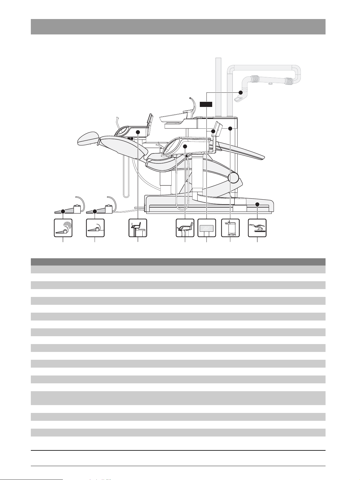
1.3
Dentist element
Assistant element
Foot control
Wireless foot control
Patient chair
Water unit
Symbols
1 – 4 D 3509.076.01.01.02 07.2008
61 94 448 D 3509

1 Important information
1.4 Abbreviations
AE Dentist element
AK Connection box
ASE Assistant element
BHE Dental treatment center
UI User interface
DNA Dürr wet suction system
PCB Printed circuit board
FS Foot control
FU Wireless foot control
GND Ground
HW Hardware
KS Four-way foot switch
LCable
LED Light emitting diode
LK Lumbar support cushion
MSBV Cuspidor valve
MV Solenoid valve
PC Personal computer
RÖBI X-ray image viewer
S Switch
SDI Sirona Dental Interface (electrical, pneumatic, hydraulic plug connection)
ST Patient chair
SW Software
VB Travel track
VDC DC voltage
WE Water unit
X Connector
bеЦдблЬ
61 94 448 D 3509
D 3509.076.01.01.02 07.2008
1 – 5
1 Important information
Board
Part No.
NAK
61 86 626
Board
Part No.
NWE
61 15 567
1.5
Stored settings
PC configuration
Date of last maintenance performed:
Display brightness
Key click
Time format
Current user
Number of users
White screen, switchable
Cursor mode
Number of chair programs
Manual chair setting at top level
Slow travel, switchable
Current timer
All timer values
All values that must be stored in conjunction with implantology/endodontics:
Number of implantology levels
NaCl cooling
NaCl rinsing amount
Instrument light
Selected endodontic file system
Auto-reverse
Handpiece
Speed
Torque
Endodontic file
Stored settings
Flushing duration
Tumbler filling time
Tumbler heating on/off
Tumbler heater temperature
Sirolux brightness
Amalgam separator filling level
AmalgamMotor operating time
SepaMotor operating time
MSBV opening time
Sanitation data
Where to save user-specific data in the TENEO
1 – 6 D 3509.076.01.01.02 07.2008
61 94 448 D 3509
1 Important information
Board
Part No.
NHE
61 15 583
Board
Part No.
NSA
61 15 591
Stored settings
NHE heater on/off
Heater temperature
Sprayvit instrument light
Sprayvit instrument light lamp voltage
Hydrocolloid duration
Stored settings
Central error storage
Tumbler filling on/off in S program
Flushing on/off in S program
SIROLUX status with chair programs
# key (switch/button)
Chair program 0, S, 1, 2 for dental user A-F
IP address
DHCP activated/deactivated
Serial numbers of the motor controls
Packaging position
Travel track positions
bеЦдблЬ
Board
Part No.
NAJ
61 28 446
Board
Part No.
DCFU
61 83 193
Stored settings
Sprayvit ventilation, AE
Activation times (instrument /instrument holder-dependent)
Instrument settings
Example:
Cooling, cooling mode, light, light intensity, foot control mode, direction of rotation,
NaCl cooling, speed, HF intensity, HF modulation
Stored settings
Minimum and maximum value of the permissible range of motion. Determined based on the reference travel.
Motor parameters
61 94 448 D 3509
D 3509.076.01.01.02 07.2008
1 – 7
1 Important information
X6
F1
F2
X29
X28
X30
X22
X21
X23
X24
X25
X15
X5
X27
X26
X18
X17
X16
X20
X19
X7
X4
X2
X1
X31
X13
F803
X14
X12
X19
X7X7
X4
X2
X11
X1
X3
X20
X13
X2
SDI
SS_MB
SS_HL
SS_HL
SS_AL
SS_RL
SS_HE
SS_HL
SS_HL
SS_HR
SS_HR
SS_HR
SS_SH
SS_HR
SS_FA
X9
X8
X14
X3
X10
X11
X13
X12
L218
S13
L332
L335
NWE
S8
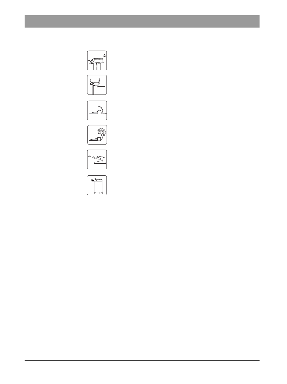
1.6
Safety switches in the dental treatment center
NSA
L317
L317
L334
L331
S6
S9
S4
S1
L332
L342
L331
L332
S11
L317
L316
L333
L316
S7
S5
S12
L333L235
S3
S2
S10
S14
1 – 8 D 3509.076.01.01.02 07.2008
61 94 448 D 3509
4.
1 Important information
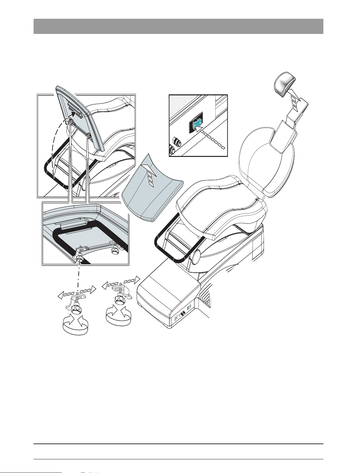
1.7 Removing the upholstery/arm rests from the patient
chair
bеЦдблЬ
2.
1.
AUS
4.
A
B
3.
B
A
1. Turn the mains power switch OFF.
2. Remove the upholstery on the headrest.
3. Loosen the screws and shift the retaining bracket B.
Remove the footrest.
4. Remove the seat upholstery.
5. Remove the backrest upholstery.
6. Pull off the backrest cover.
7. Press the release button on the armrest and pull out the armrest.
61 94 448 D 3509
D 3509.076.01.01.02 07.2008
1 – 9
1 Important information
1.8
6.
6.
2.
3.
1.
7.
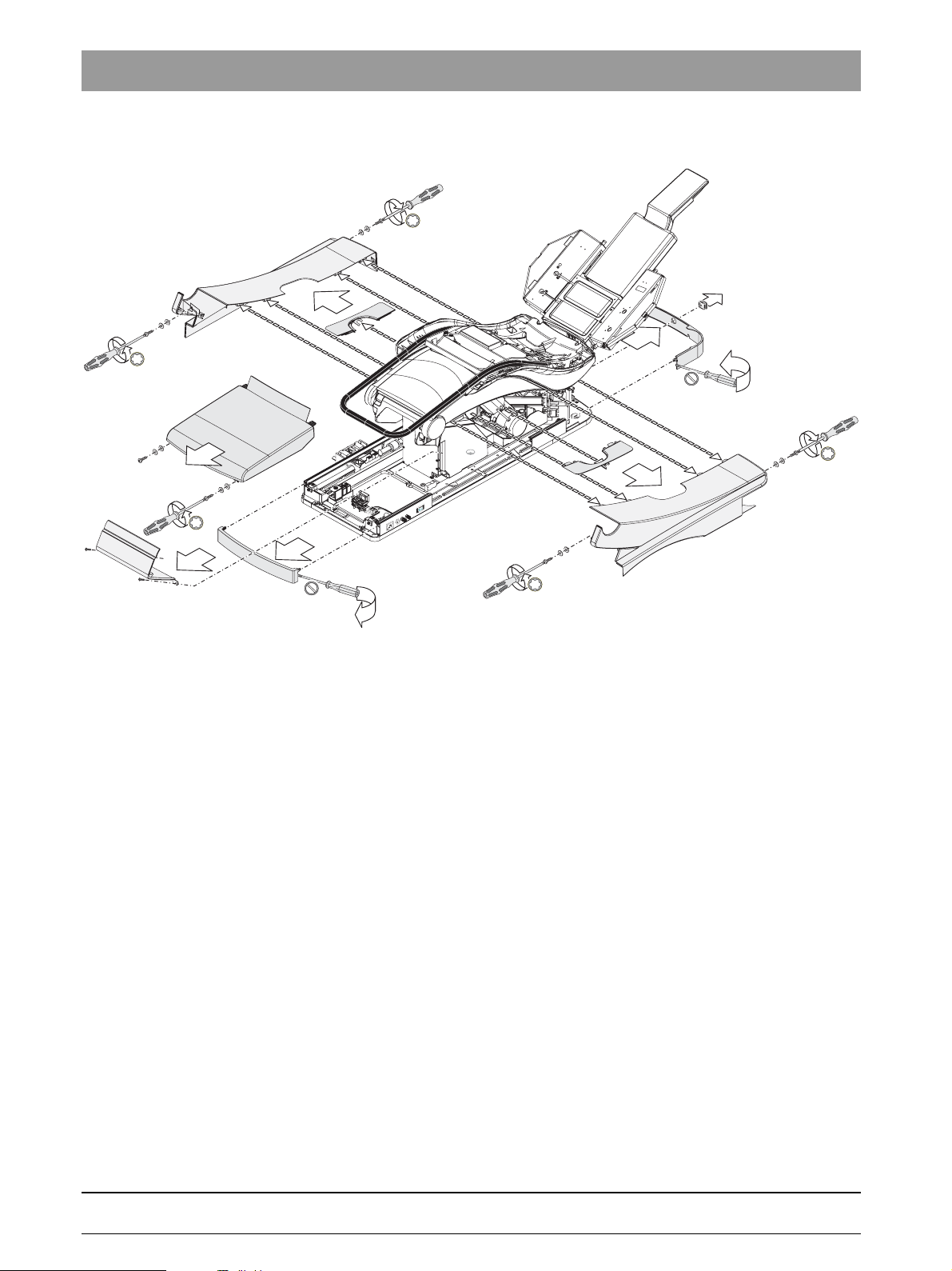
Removing the cover panels of the patient chair
4.
5.
6.
7.
6.
1. Remove the front faceplate of the base.
The faceplate is fitted on the lateral covers (if necessary, carefully pry
them apart with a screwdriver).
2. Unscrew the two screws (with washers) at the front of the cover.
Take off the cover.
3. Unscrew the two screws of the cover. Remove the cover (snap).
4. Pull off the small bellows from the four-way foot switch (if present).
5. Remove the rear faceplate of the base. The faceplate is fitted on the
lateral guide rails (if necessary, carefully pry them apart with a
screwdriver).
6. Remove the four screws of the side panels of the stand and remove the
covers.
7. Pull off the right and left covers.
1 – 10 D 3509.076.01.01.02 07.2008
61 94 448 D 3509
1 Important information
i
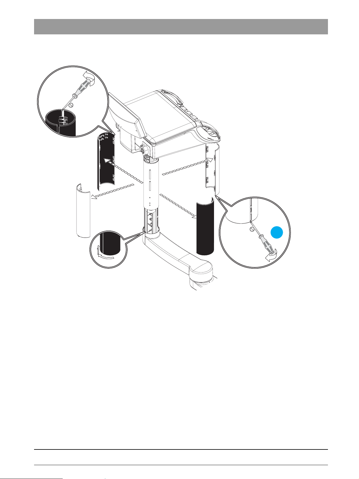
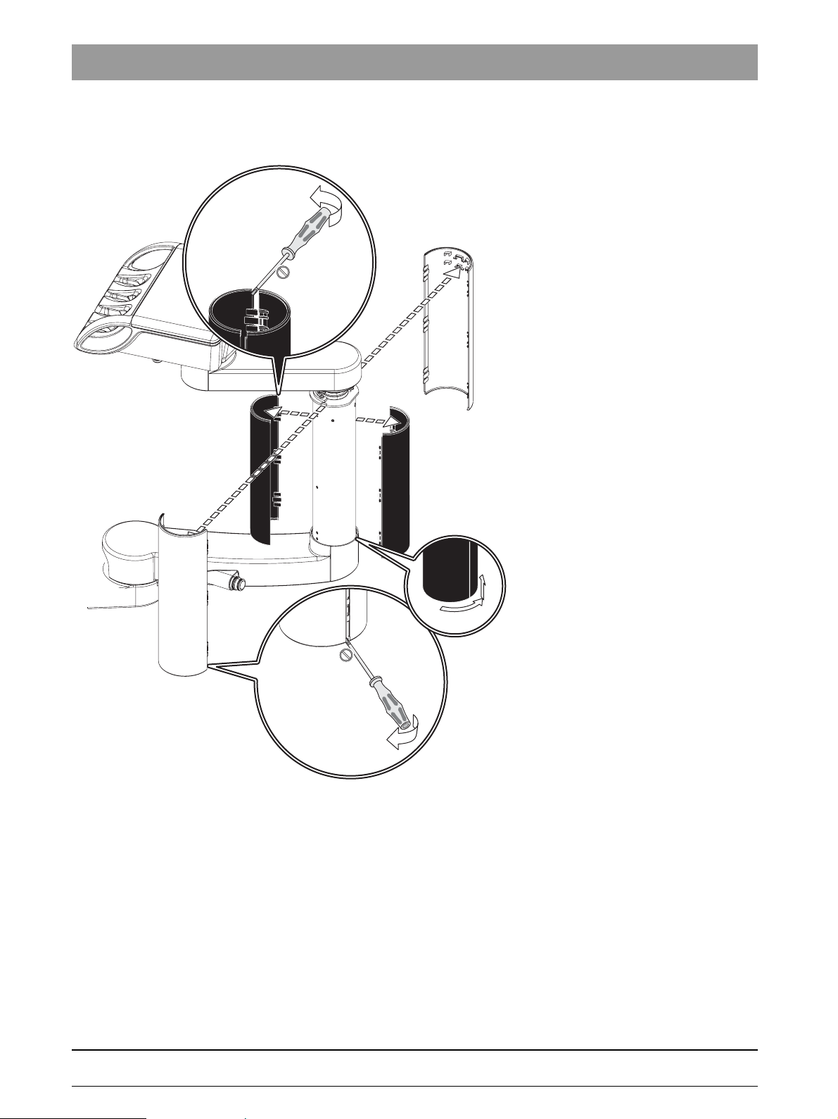
1.9 Removing the cover panels of the support arm of the
3.
1.
bеЦдблЬ
3.
1.
Dentist Element max.Assist.Element max.
3.
1.
2.
dentist element.
1. Remove the outer half-shell covers.
2. Detach the inner half-shell covers from the bayonet connector and move
them upward.
3. Remove the inner half-shell covers.
61 94 448 D 3509
D 3509.076.01.01.02 07.2008
1 – 11
1 Important information
4.
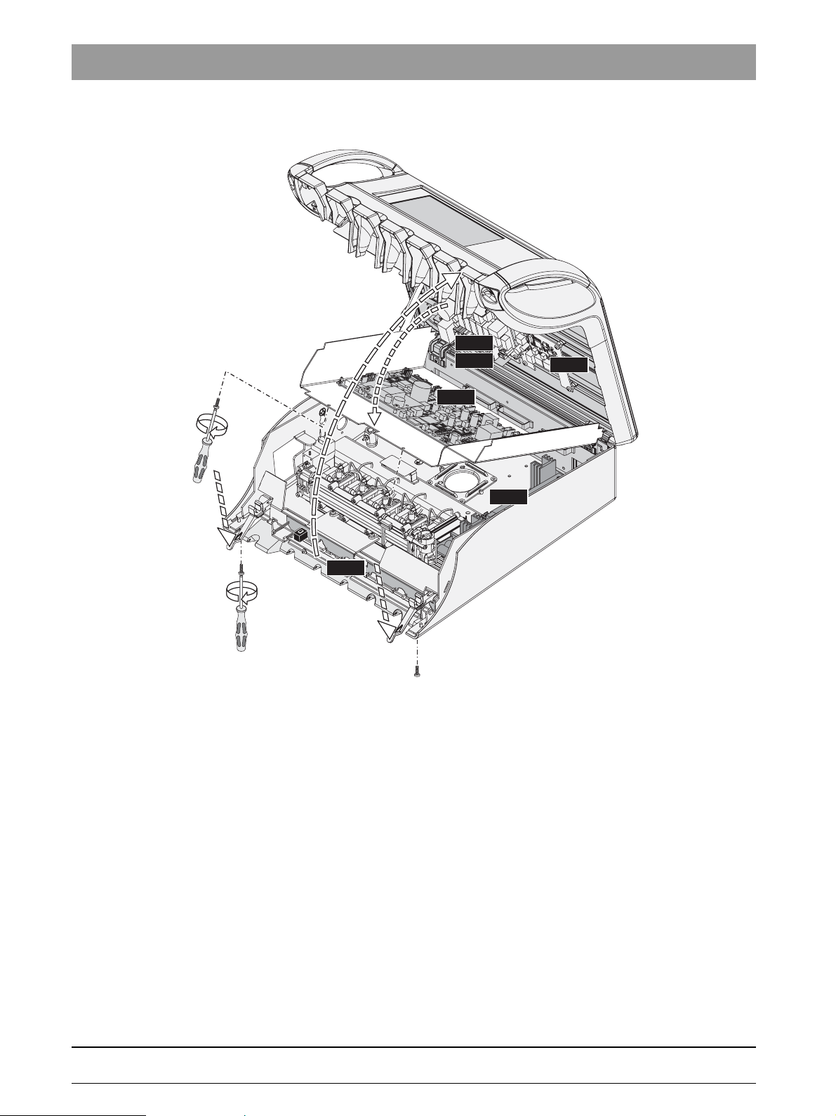
1.10
Opening the dentist element
3.
NAC
NAL
NAJ
NAU
5.
HF
2.
CC
1.
2.
1. Unscrew the two screws.
2. Press the locking bar.
3. Lift the cover upwards and let it lock it into the upright position.
4. Unscrew two screws and
5. fold down the PCB holder plate.
1 – 12 D 3509.076.01.01.02 07.2008
61 94 448 D 3509
1.
2.
2.
3.
NAB
NAK
1 Important information
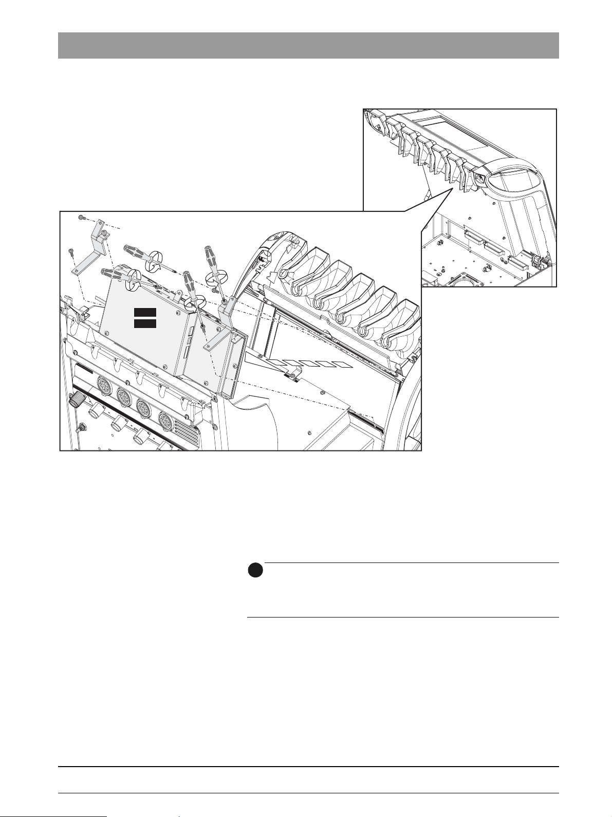
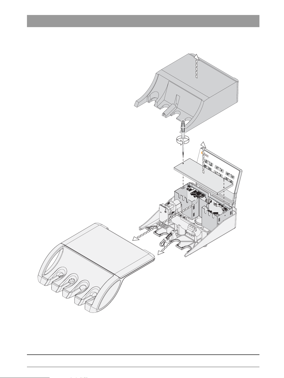
1.11 Removing the user interface on the dentist element
bеЦдблЬ
1. Loosen the setscrew.
2. Unscrew the upper screws of the retaining bracket.
Loosen the lower screws of the retaining bracket.
Turn the right retaining bracket outwards to the right and the left retaining
bracket outwards to the left.
Pull the connector X1 off of the user interface.
3. Unscrew the screw and remove the user interface panel.
i
NOTE
When re-assembling the unit:
Tighten the setscrews 1 and 3 (these are not fastening screws) only until the
user interface panel is fixed in place.
61 94 448 D 3509
D 3509.076.01.01.02 07.2008
1 – 13
1 Important information
3.
1.12
1.
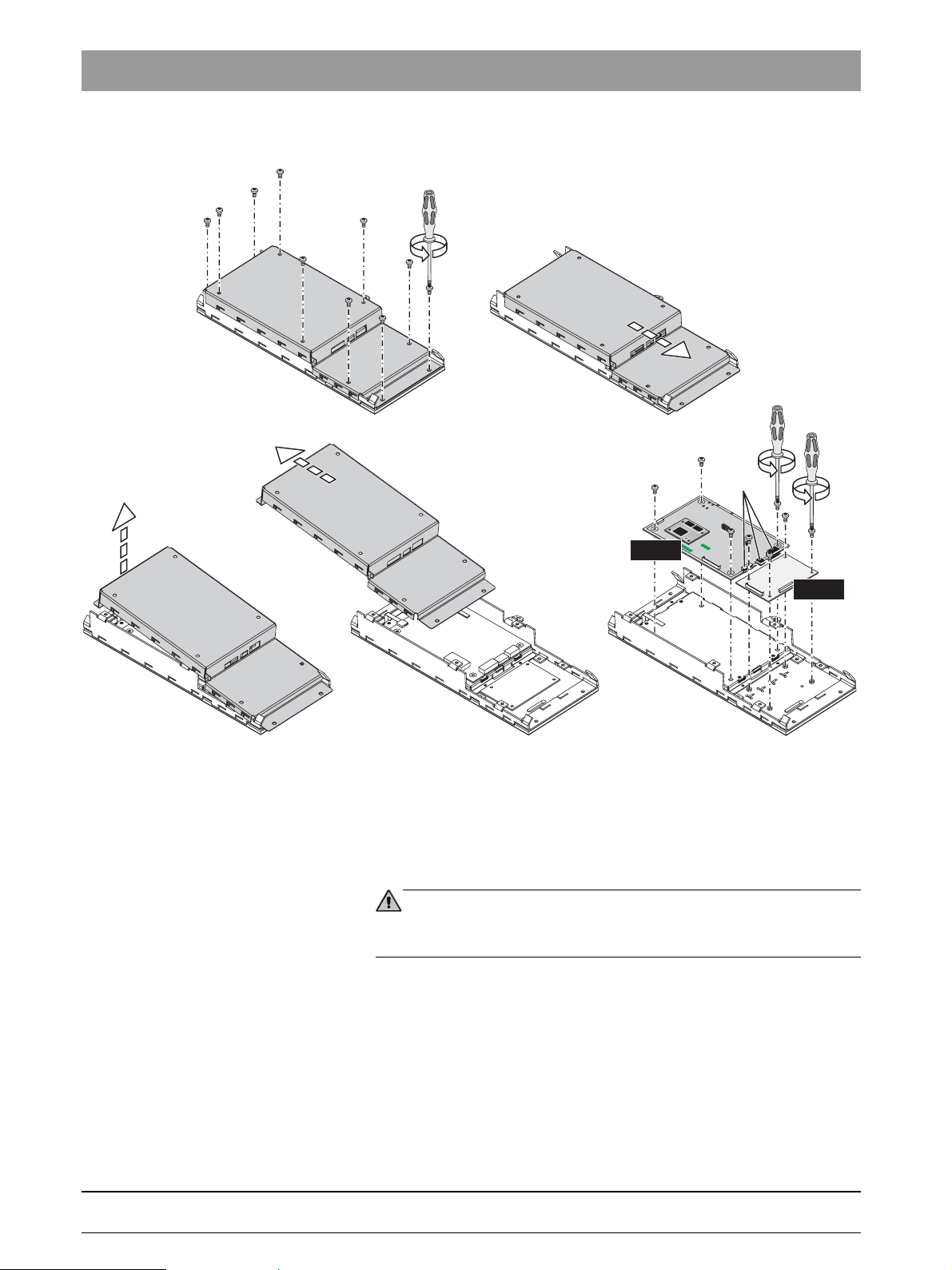
Removing the NAK and NAB boards
2.
ca. 1cm
X1
X2
X3
4. 5.
NAK
NAB
1. Unscrew the ten screws.
2. Push the cover approximately 1 cm to the right.
3. Lift the left side of the cover and
4. Remove the cover diagonally to the left.
5. Unscrew the boards.
CAUTION
Pay attention to the connectors X1, X2 und X3 on the NAK board when putting
the cover back on!
61 94 448 D 3509
1 – 14 D 3509.076.01.01.02 07.2008
1 Important information
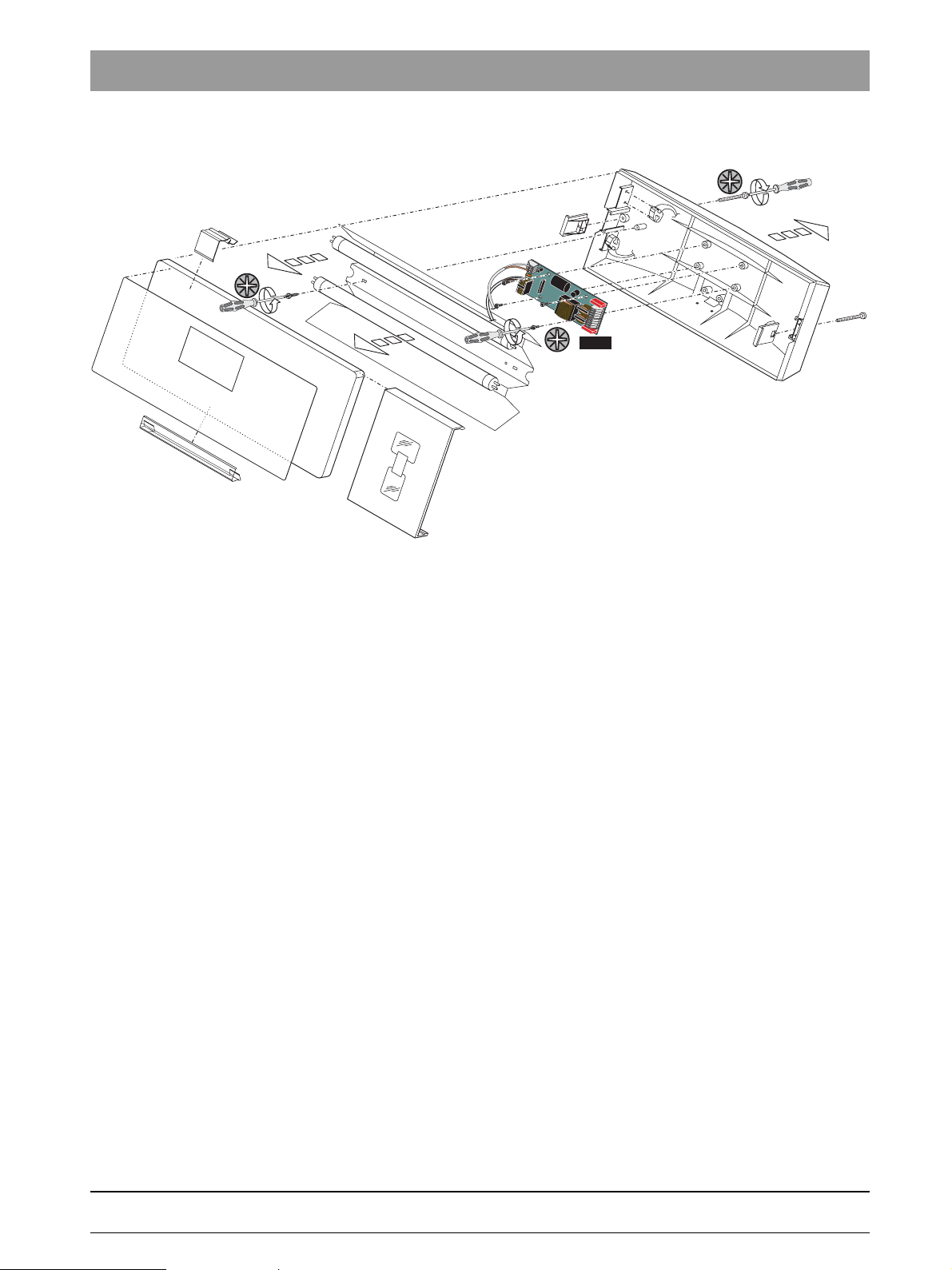
1.13 Removing the NAR board for the X-ray viewer
1.
bеЦдблЬ
3.
2.
1. Unscrew two screws and pull off the back wall.
2. Remove the fluorescent lighting tubes.
3. Unscrew two screws and take off the reflector.
4. Unscrew four screws and remove the NAR board.
4.
NAR
61 94 448 D 3509
D 3509.076.01.01.02 07.2008
1 – 15
1 Important information
3.
1.14
Removing the cover panels of the support arm of the
assistant element.
1.
3.
2.
1.
1. Remove the outer half-shell covers.
2. Detach the inner half-shell covers from the bayonet connector and move
them upward.
3. Remove the inner half-shell covers.
1 – 16 D 3509.076.01.01.02 07.2008
61 94 448 D 3509
1 Important information
1.15 Removing the cover panels of the assistant element
1.
bеЦдблЬ
1.
1.
2.
2.
C
NHE
NOP
61 94 448 D 3509
D 3509.076.01.01.02 07.2008
1. Pull the bar and remove the cover panels.
2. Unscrew two screws and remove the cover.
1 – 17
1 Important information
1.
3.
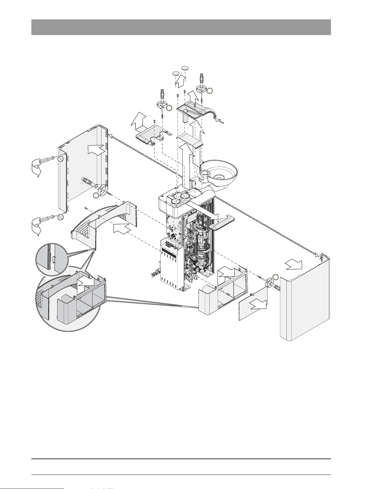
1.16
7.
Removing the cover panels from the water unit
6a.
8.
5.
A
4.
6.
3.
4
3
5
2
6
1
r
a
0
b
4
3
5
2
6
1
r
a
0
b
1.
3.
2.
1. Carefully pry apart the side panels.
Pull off the side panels.
2. Take off the service cover.
3. Unscrew the two screws on each of the covers, unhook and remove
covers.
4. Take off the cover.
5. Unscrew the four screws on the cover.
6. Remove the cover, 6a.. Remove the cover.
7. Unscrew the two screws on the cover and remove the cover.
8. Remove cover panel funnel.
Pay attention to snap-in nose A.
1 – 18 D 3509.076.01.01.02 07.2008
61 94 448 D 3509

TENEO
2 Overview of modules and boards
2.1 Locations of modules and boards
2.1
Locations of modules and boards
oder
ASEFSFU STAE WERÖBI
Component Board/module
ST Patient chair DCFU Motor control ( 3 units)
NSA Connection box
NSB Base station wireless foot control
NSC Seat connect
NSK Headrest
NSU USB connection to chair
FS Foot control
FU Wireless foot control NSF Wireless foot control
AE Dentist element CC instrument holder recognition AE (6 x)
RÖBI X-ray viewer
on the AE or tray support arm WE
ASE Assistant element NHE ASE control
WE Water unit NWE WE control
+
HF
NAB User interface AE LED board
NAC Motor control BL
NAJ AE control
NAK User interface AE baseboard
NAL Motor control SL
NAU USB connector to AE
NAR X-ray viewer board
NHT User interface ASE
NOP 5 V power supply
NWM Automatic tumbler filling
surgery module
2 – 2 D 3509.076.01.01.02 07.2008
61 94 448 D 3509

2.2 ... In the patient chair
M3
M2
M1
2.2.1 DCFU board - Motor control board
DCFU für Rückenlehnenneigungs-Motor
2.2 ... In the patient chair
DCFU
X5
DCFU
V1
V2
DCFU für Rückenlehnen-Motor
Board Components on the board
DCFU Motor control
Backrest motor
V2 status LED (Yellow) Flashing 2 Hz > Motor running
M3
V3 36 V LED (Green)
X1 > L326 > X9 NSA Power supply
X2 > M3 Motor connection
X4 > L324 > X10 NSA Control line
X5 > L345 > Light barrier for reference travel and adjustment
X6 > Sensor Angular momentum sensor of motor
Board Components on the board
DCFU Motor control
Backrest inclination motor
V2 status LED (Yellow) Flashing 2 Hz > Motor running
M2
V3 36 V LED (Green)
X1 > L326 > X9 NSA Power supply
X2 > M2 Motor connection
X4 > L324 > X10 NSA Control line
X5 > L346 > Light barrier for reference travel and adjustment
X6 > Sensor Angular momentum sensor of motor
Board Components on the board
DCFU Motor control
Lift motor
V2 status LED (Yellow) Flashing 2 Hz > Motor running
M1
V3 36 V LED (Green)
X1 > L325 > X7 NSA Power supply
X2 > M1 Motor connection
DCFU
bеЦдблЬ
X4
X6
DCFU für Hub-Motor
X1
X2
DCFU
V3
ON > Motor idling
Flash code > Service message to NSA board
ON > Motor idling
Flash code > Service message to NSA board
ON > Motor idling
Flash code > Service message to NSA board
61 94 448 D 3509
D 3509.076.01.01.02 07.2008
2 – 3

2.2 ... In the patient chair
M3
M2
M1
Board Components on the board
X4 > L308 > X29 NSA Control line
X5 > L344 > Light barrier for reference travel and adjustment
X6 > Sensor Angular momentum sensor of motor
V2 status LED (Yellow) Flashing 2 Hz > Motor running
Function of the DCFU board
Activated by the NSA board serially via CAN.
Control of the three-phase drives in the patient chair.
Acknowledgment of the motion via sensors in the motor.
Position recognition via counting of the pulses by the software of the DCFU board.
Communication of the motor position to the NSA board.
Motor locations
ON > Motor idling
Flash code > Service message to NSA board
2 – 4 D 3509.076.01.01.02 07.2008
61 94 448 D 3509

2.2 ... In the patient chair
2.2.2 NSA board - Connection box
X14
X12
X3
X10
X13
V
V633
629
V
V623
618
V
X
X21
X
X26
X
X24
X
X22
5
0
V
3
5
0
V
8
4
1
V
1
4
0
V
1
4
0
V
3
4
V
3
0
V
6
3
0
V
1
3
0
3
V
1
1
V
0
1
2
1
V
0
1
1
1
0
0
18
27
25
23
17
X
31
X
5
X
4
X
939
X
V
X
1
X2
16
X
0
4
V
3
0
7
V
1
0
0
V
9
0
V
9
0
V
9
V
9
20
15
X
19
X
30
X
28
X
1
2
1
3
3
V
V209
5
7
4
V
V212
X11
0
2
4
1
6
509
V
V215
V
201
V
2
3
8
V
2
3
9
V743
X9
X8
NSA
V
744
V
745
V
7
4
0
X6
F1
F2
X29
X7
NSA
bеЦдблЬ
Board Components on the board
NSA Patient chair control F1 - T10AH 250V P Dentist element
F2 -T 10 AH 250 V P Assistant element
V201 - 36 V (Green)
V209 - 3.3 V (Green)
V212 - 5 V_Poti (Green)
V215 - 5 V (Green)
V238 - 36 V_AE (Green)
V239 - 36 V_HE (Green)
V503 - 3 V WDT (Green)
V303 - RESET (red) Lights up briefly after the unit is switched on
V508 - Safety Stop (red) ON > Locking of the motors, MVs, relay
> 1. Update software or
V901 - OC Track (red) ON > Overcurrent shutdown travel track
> Short circuit in motor 6 or in the line L309
V902 - OC Clutch (red) ON > Overcurrent shutdown travel track clutch
> Short circuit in the clutch or in line L309
V307 - ERROR (red) Flash code >
61 94 448 D 3509
D 3509.076.01.01.02 07.2008
2. Replace board
2 – 5

2.2 ... In the patient chair
Board Components on the board
V402 - SS Code (red) Flash code Active safety switch
V411 - Chair stop active (Yellow) ON > Motion lock by active instrument
V416 - HR_Stop (Yellow) ON > Motion lock by active instrument
V623 - Bell relay (Yellow)ON > Relay actuated
V629 - Auxiliary relay (Yellow)ON > Relay actuated
V633 - Suction relay (Yellow)ON > Relay actuated
V740 - 36 V M1 (Yellow) ON > 36 V Motor 1 enabled
V743 - 36V M2 (Yellow) ON > 36 V Motor 2 enabled
V744 - 36V M3 (Yellow) ON > 36 V Motor 3 enabled
V745 - 36 V NSC (Yellow) ON >NSC board enabled
V935 - Track (Yellow) ON > Move travel track close
V937 - Track (Yellow) ON > Move travel track away
V939 - Clutch (Yellow) ON > Travel track clutch activated
V1001 - FS active (Yellow) ON > Foot control pedal activated
V1100 - LAN Speed LED (Yellow) ON > 100 Mbit
V1101 - LAN Link/Activity (Yellow) ON > When connected
V1102 - LAN Full Duplex (Yellow) ON > If full duplex
X1 > L307 > SDI2 X1.1 - X1.10 > L248 > X22 NAJ
X2 > L305 > X6 > L205 > X5 NWE
X3 > L306 > X3 NSC
X4 > L340 > SDI2 X2.1 - X2.10 > L231 > X4 NHE
X5 > L311 > X5 NSB
X6 > L302 > X3 > L202 > X2 power supply
X7 > L325 > X1 DCFU M1 power supply
X8 > L303 > X1 NSC power supply
X9 > L326 > X1 DCFU M2 and DCU M3 power supply
X10 > L324 > X4 DCFU M2 and DCU M3 control line
X11 > L316 > S12 SS-SH
X12 > L317 > S1 - S4 SS-HR
X13 > L333 > SDI2 X2.12 - X2.13 > L235 > S14 SS_HE > L232 > X1 NHE
X14 > L331 > S5 - S8 SS_HL
> L334 > S9 SS_FA
> L332 > S10 SS_RL
> L335 > X13 > L342 > S11 SS_AL
X15 > L312 > 4-way foot switch
X17 > L309 > M6 4-way foot switch
X18 > L310 > X7 Poti 4 way foot switch
2x > Chair lift and cuspidor bowl
3x > Lifting frame
4x > Assistant element
5x > Handrail
6x > Footrest
7x > Backrest
8x > Armrest
9x >Malfunction in communication to user interface
10x > Total tilt implausible
1. Carry out reference travel
2. Replace NSC
11x > Chair stop active = LED 411
12x > Total tilt invalid
OFF > 10 Mbit
Flashes > During LAN data transmission
OFF> If half duplex
2 – 6 D 3509.076.01.01.02 07.2008
61 94 448 D 3509

Board Components on the board
X19 > L313 > X8 / X9 > L314 C2+ foot control
X20 > L313 > X8 / X9 > L314 C2
X21 > RJ45 > L339 > RJ45 External PC Sivision
X26 > L328 > MVP1 - MVP3
X27 > MVAB
X28 > L341 > SDI2 X2.14 - X2.15
X29 > L308 > X4 DCFU M1 Control line
X30 > L315 > SDI2 X1.14 / X1.15 > L249 > X22 NAJ
+
foot control
Function of the NSA board
Travel track activation
Activation of the main input valves for air/water
Activation of the valve block for the media in the dentist element (SV and PV)
Enabling of wireless foot control (optional)
Evaluation of four-way foot switch
Evaluation C
System clock (RTC)
Evaluation of the position sensor on the NSC board
Communication with the user interface via S-CAN
Communication with the DCFU boards
Power supply for the DCFU boards
Communication with the NSC board
Communication via Ethernet with the PC
Power supply for the electronic circuit of the assistant element
Power supply for the electronic circuit of the dentist element
Evaluation of all safety switches
Software update via LAN / Implementation of the Ethernet protocol on S-CAN
+
of foot control
2.2 ... In the patient chair
bеЦдблЬ
i
NOTE
If the safety switch S12 is active (V402/SS code/Flashes 2x), the chair can only move upwards when the cuspidor bowl is
swiveled inwards.
Communication via CAN with the NSK board
Power supply of the NSK board
61 94 448 D 3509
D 3509.076.01.01.02 07.2008
2 – 7

2.2 ... In the patient chair
2.2.3 NSB board - Wireless base station
V208
V209
V207
V21o
NSBNSB
V400
Board Components on the board
NSB Wireless foot control base
station
V207 - SP (Yellow) Pedal
V208 - CL (Yellow) Cursor right
V209 - CR (Yellow) Cursor left
V210 - CB (Yellow) Cursor down
V211 - CF (Yellow) Cursor up
V213 - Bat (Red) ON > Replace battery in wireless foot control
V214 - SL (Yellow) S / Spray
V216 - SR (Yellow) O / Chip blower
V221 - WDT (Red) ON > Cable foot control connected or no CAN
V300 - 36 V (Green)
V301 - 3.3 V (Green)
V308 - 2.5 V (Green)
V311 - 5 V (Green)
V400 - RUN (Green) Must flash with 1 - 2 Hz in normal status
V402 - BOOT (Yellow) Lights up briefly when booting
V403 - RESET (Red) Lights up briefly after the BHE is switched on
X5 > L311 > X5 NSA
V402
V308
V211
V214
V216
V213
V221
V300
X5
NSB
V403
V301
V311
communication or NSB board defective
Flashing > Overcurrent protection on foot control line active
> Flashing 1 Hz = Login procedure active
Function of the NSB board
Wireless base station for devices connected by wireless (e.g. wireless foot control).
Communication with the other boards via CAN.
Transmission frequency 2.4 GHz
61 94 448 D 3509
2 – 8 D 3509.076.01.01.02 07.2008

2.2.4 NSC board - Seat connect
X1
X5
X1
X1
X1
V9
V17
2.2 ... In the patient chair
V48
V39
V29
V24
V50
V30
V35
V31
V36
V37
V40
V41
bеЦдблЬ
V23
NSC
X2
X5
X4
X3
X1
Board Components on the board
NSC Seat connect V23 - 3.3 V (Green)
V24 - MVKP4 (Yellow)Deflate upper cushion Massage
V29 - MVKP3 (Yellow)Inflate upper cushion Massage
V39 - MVKP2 (Yellow)Deflate lower cushion Massage lumbar support
V48 - MVKP1 (Yellow)Inflate lower cushionMassage lumbar support
X1 > L303 > X8 NSA
X2 > L338 > X14 > Solenoid valves MVKP1 / MVKP2
X2 > L338 > X15 > Solenoid valves MVKP3 / MVKP4
X3 > L306 > X3 NSA
X4 > L322 > X10 > L323 > X4 NSK
NSC
Function of the NSC board
Activation with serial interface of NSA board with IIC bus.
Evaluation of the position sensor for the seating angle.
Forwarding of the CAN connection to the NSK board.
Activation of the solenoid valves for massage support.
For the active lumbar support support, only the lower cushion is inflated.
For massage, the lower and upper cushions are alternately inflated.
61 94 448 D 3509
D 3509.076.01.01.02 07.2008
2 – 9

2.2 ... In the patient chair
X14
X15
Solenoid valve for massage/active lumbar support
A58
A57
MVKP1
MVKP2
MVKP3
MVKP4
A55
Components
MVKP1 - Lumbar support inflation
MVKP2 - Lumbar support deflation
MVKP3 - Massage inflation
MVKP4 - Massage deflation
MVKP3 / MVKP4 > X14 > L338 > X2 NSC
MVKP1 / MVKP2 > X154 > L338 > X2 NSC
2 – 10 D 3509.076.01.01.02 07.2008
61 94 448 D 3509

2.2.5 NSK board headrest
NSK
V523
V
405
V
502
V410
5
0
2
2
0
5
3
0
5
2
V
6
V
6
V
V
5
2
6
6
V
V
V307
V
301
V
303
V306
0
2
0
0
4
V
1
0
9
15
2
2
0
2
1
V
2
V
2
V
V
2.2 ... In the patient chair
bеЦдблЬ
X4
1
X
NSK
Board Components on the board
NSK Headrest V201 - 36 V ( Green)
V209 - 3.3 V ( Green)
V212 - 3.3V Poti (Green)
V215 - 5 V ( Green)
V301 - RUN (Green) Flashes in normal operation
V303 - RESET (Red) Lights up briefly after treatment center is switched on.
V306 - BOOT (Yellow)
V307 - ERROR (Red)
V402 - 3V_WDT (Green) ON > OK
V405 - Headrest stop M5 (Yellow)Directly connected with HR_Stop (V416) from NSA board
V410 - Safety Stop (Red) OFF > OK
V500 - OC_Headrest tilt M5 (Red) ON > Short circuit in tilting section of motor/line
V502 - Headrest tilt block M5 (Yellow)ON > Motor brake for tilt section active
V523 - Headrest tilt M5 (Yellow)Headrest backward
V525 - Headrest tilt M5 (Yellow)Headrest forward
V600 - OC_Headrest M4 (Red) ON > Short circuit in motor/line for size adjustment
V602 - OC_Headrest block M4(Yellow)ON > Motor brake size adjustment active
OFF > and V201 ON > Replace NSK board
OFF > and V201 OFF > Check line 36 V
ON > Motion locking via active instrument
ON > Check V405
ON > Motor control blocked by NSA board
OFF > Check RUN-LED
OFF > Update software
Flashing > Replace N>SK board
D 3509.076.01.01.02 07.2008
2 – 11
61 94 448 D 3509

2.2 ... In the patient chair
Board Components on the board
V623 - OC_Headrest M4 (Yellow)Extend motor for size adjustment
V625 - OC_Headrest M4 (Yellow)Retract motor for size adjustment
X1 > L327 > M5 tilt component
X1 > L337 > Poti tilt component
X1 > L321 > M4 size adjustment > Poti size adjustment
Function of the NSK board
Activation and evaluation of size adjustment
Activation and evaluation of overstretch.
Communication with the other boards via CAN.
Evaluation of the four-way switch in the headrest.
2 – 12 D 3509.076.01.01.02 07.2008
61 94 448 D 3509

2.2.6 NSU board - USB connection to patient chair
NSU
2.2 ... In the patient chair
X11
X12
V12
NSU
bеЦдблЬ
V3
V4
X5
X1
V7
X2
X3
V11
V8
V9
Board Components on the board
NSU USB connection to patient
V3 - 5V (Green)
chair
V4 - 3V3 (Green)
V7 - X5 (Green) USB connection to external PC
V8 - X2 (Green) ON > If USB device on X2
V9 - X3 (Green) ON > If USB device on X3
V11 - X1 (Green) ON > If USB device on X1
V12 - 12V5 (Green)
X1 > L330 > X1 SDI
X5 > L348 > USB repeater > L343 > External PC
X11 > L320 > X4 > L203 > X6 Power supply
Function of the NSU board
In the patient chair it forms the interface between the PC connection and the USB applications in the dentist element.
The integrated power supply unit supplies a current of 2000 mA for the power supply of the USB connections.
The NSU board provides 12.5 V for the NAU board in the dentist element.
61 94 448 D 3509
D 3509.076.01.01.02 07.2008
2 – 13

2.3 ... in the foot control
S
0
NSF
2.3
... in the foot control
2.3.1 Wireless foot control
V4
Board Components on the board
NSF Wireless foot control
V4 - As long as the login procedure is running, the reflection of the green flashing LED is visble
on the step.
The flashing stops when the login has been successfully completed or after 30 seconds
without a login.
Battery status indicator during battery insertion:
10 sec ON > Battery usable
10 sec FLASHING > Replace battery
OFF > Battery empty or NSF board defective
61 94 448 D 3509
2 – 14 D 3509.076.01.01.02 07.2008

2.4 ... in the dentist element
2.4.1 CC board - instrument holder recognition in the dentist unit
CC
2.4 ... in the dentist element
bеЦдблЬ
V1
V11
X1
Board Components on the board
CC Instrument deposit
acknowledgment
V2
V12
V3
V13
V4
V14
V5
V15
V1 / V11 Sensor holder 1
V2 / V12 Sensor holder 2
V3 / V13 Sensor holder 3
V4 / V14 Sensor holder 4
V5 / V15 Sensor holder 5
V6 / V16 Sensor holder 6
X1> L260 > X12 NAJ
CC
V6
V16
Function of the CC board
Acknowledgment of instrument removal in the holder of the dentist element via infrared transmitter/receiver.
Not compatible with the C line.
61 94 448 D 3509
D 3509.076.01.01.02 07.2008
2 – 15

2.4 ... in the dentist element
2.4.2 HF+board - Surgery module
V9
V25
V26
X10
V24
V27
V23
X6
X7
X2
X4
X5
Board Components on the board
+
HF
Surgery module F1 - 4AM 36 V DC
X1
+
HF
R51 - Buzzer volume
V9 - Voltage in end phase (Green)
V23 - +5 V (Green)
V24 - Function check (Green)
V25 - HF active (Green)
V26 - CAN check (Green)
V27 - RESET (Red) Lights up briefly after treatment is switched on.
X1 > L252 > X32 NAJ 36 V DC power supply
X2 > L252 > X32 NAJ CAN / foot control
X4 > Flange_HF
X5 > Connection to ground wire
X6 > Flange_HF hose code
X7 > Code Pin 2 / Pin 3 must be connected
X10 > Jumper C1 / C2 must be connected at C1
R51
F1
HF
+
Function of the HF+ board
Generates the high frequency of the Sirotom handpiece.
The one pin of the high voltage is the tip of the handpiece, the other is the ground / casing.
Control via CAN.
Overheating guard at the end phase.
Generation of the operating tone with active HF.
The HF module is switched on for a few seconds after the dental treatment center is switched on. During this period the
HW/SW status is queried and the module carries out a self-test. Subsequently the module is switched off again. When the
HF handpiece is removed, the module is switched on again and carries out a brief self-test. When the handpiece is
returned to its place, the module is switched off again.
For operation in this dental treatment center, the code bridge X10 must be set to position "C1" and the code bridge at X7
must be connected to Pin 2 / Pin 3.
When HF is activated, the video circuit is shut off in the power pack and switched on again when the handpiece is
replaced. This is necessary so that no interference is visible on the screen when HF is active. When the video circuit is
switched off, the USB power supply and thus the USB camera are switched off.
61 94 448 D 3509
2 – 16 D 3509.076.01.01.02 07.2008

2.4.3 NAC board - BL motor control
2.4 ... in the dentist element
V204
V236
V205
V212
V301
V302
V303
V312
V311
V310
V304
V203
V901
X8
X6
NAC
X1
X5
X12
X13
X14
X15
X3
NAC
Board Components on the board
NAC BL motor control V203 - 3V3 (Green)
V204 - 3V3 (Green) analog
V205 - 5 V (Green)
V212 - 12 V (Green)
V236 - +36 V (Green)
V301 - RUN (Yellow) Flashes during standby 1 Hz
V302 - TEST 1 (Yellow) Lights up when foot control is activated
V303 - TEST 2 (Yellow) Lights up when motor controller J416 is in error status
V304 - BOOT (Yellow)
V310 - RESET (Red) Lights up briefly after unit is switched on
V311 - ERROR (Red)
V312 - CLAW (Yellow) Indicates the active instrument holder via flash code
V901 - 5V (Yellow) from NAJ
X1 > L248 > X1.16 / X1.17 AK
X3 > L251 > Flange_Scaler
X5 > Option_PK_Supply
X6 > Option_PK_Communication
X8 > L244 > X8 NAJ
X12 > L258 > Holder 2
X13 > L258 > Holder 3
X14 > L258 > Holder 4
X15 > L258 > Holder 5
bеЦдблЬ
Flashes when instrument is active 10 Hz
61 94 448 D 3509
D 3509.076.01.01.02 07.2008
2 – 17

2.4 ... in the dentist element
Function of the NAC board
This board is integrated in the workstation via CAN and takes over the control of the brushless dental motors and turbines.
Supply for instrument light (halogen or LED).
2 – 18 D 3509.076.01.01.02 07.2008
61 94 448 D 3509

2.4 ... in the dentist element
V600
V304
V303
V201
V212
2.4.4 NAJ board - Dentist element control
X6
X5
V719
X12
X20
X19
V405
X24
X21
X15
X8
V501
V102
X7
X22
X1
NAS
V212
V212
V201
NAJ
J11
J12
J13
S1
V600
V600
V304
V304
V303
V201
Board Components on the board
NAJ Dentist element control J11 > SW Option 1)
J12 > SW Option 2)
J13 > SW Option 3)
S1 > S1.1 ON > Ultrasound on instrument holder pos. 6
OFF > Ultrasound on holder pos. 5
S1.2 ON > Camera on external holder pos. 7
OFF > Camera on holder pos. 6
V102 - Chair Stop (Yellow)
V201 - 36 V (Green)
V211 - 26V5 (Green)
V212 - 5 V (Green)
V216 - 3V3 (Green)
V300 - HB (Green) Flashes during normal operation
V302 - BL (Yellow) Lights up briefly while booting
V303 - ERROR (Red) Flash code
V304 - RESET (Red) Lights up briefly after unit is switched on
V305 - User (Yellow) Lights up when at least one instrument has been removed
V405 - NaCl (Yellow) ON > NaCl pump switched on
V501 - 36V (Green) ON > Heater switched on
V600 - FPGA (Yellow) Flashing > OK (configuration is loaded)
V719 - P5V (Green) ON > Sprayvit removed Sprayvit supply on
V1002 - 36V_AUX (Green)
V1003 - 36V_HF (Green)
X1 > L246 > X1 NAP
X2 > L250 > Flange_Scaler
X5 > L256 > Holder 1 Sprayvit with light, air and water heater
X6 > L256 > Holder 1 Sprayvit with light, key and hose coding
X7 > L245 > Spray water heater
X8 > L244 > X8 NAL
X12 > L260 > X1 CC
V1002
V1003
NAJ
X32
NAS
X2
V216
V211
V305
V302
V300
Permanently ON > Connection to NSA board not present
or NAJ board is defective
Lit up> US scaler active
bеЦдблЬ
61 94 448 D 3509
D 3509.076.01.01.02 07.2008
2 – 19

2.4 ... in the dentist element
Board Components on the board
X15 > L247 > X-ray viewer
X19 > MV_21_1 - MV_21_4 / MV_22_ZEG_Water / MV_23_ZEG_Air /
X21 > L248 > X1.14 / X1.15 AK
X21 > L248 > X1.14 / X1.15 AK
X21 > L248 > X1.14 / X1.15 AK
X21 > L248 > X1.14 / X1.15 AK
X22 > L249 > X1.1 - X1.10 AK
X24 > NaCl
X32 > L252 > X1.1 , X1.2 HF+
X2.1B, X2.2B HF+
X2.3B, X2.4B HF+
Function of the NAJ board
The NAJ board controls the dentist element functions.
The board is part of the basic equipment of the dentist element in the dental treatment center.
The following functions have been implemented:
- Control of the Sprayvit and ultrasound instruments and intraoral video camera
- Instrument removal acknowledgment
- Control of solenoid valve, med. solution, standard (water) heater, light barrier 5/6 on the instrument holder, NaCl pump
- Control and power supply for optional board for X-ray viewer
- Communication with the NAL instrument controls (for SL) and NAC (for BL motors)
- Interface to user interface
- Interfaces for 3 HW dongles (J11 / J12 / J13)
- Control and interface for optional HF and apex
MV_24_Sprayvit_Water / MV_25_Sprayvit_Air
S1 switch settings:
OFF ON
S1.1 Ultrasound
ON ON Ultrasound on instrument holder pos. 6 / Camera on external holder pos. 7
ON OFF Not permissible (ultrasound does not work)
OFF ON Ultrasound on instrument holder pos. 5 / Camera on external instrument holder pos. 7
OFF OFF Ultrasound on instrument holder pos. 5 / Camera on instrument holder pos. 6
S1.2 CAMERA
Function
2 – 20 D 3509.076.01.01.02 07.2008
61 94 448 D 3509

2.4 ... in the dentist element
2.4.5 NAK board - User interface to dentist element baseboard and NAB board LED board
X21
X
14
GND
Keyb
Board Components on the board
NAK User interface to dentist
element baseboard
NAK
36V
3,3V
Run
Error
Reset
BackI
X11
LED 3V3 - (Green) Operating voltage
LED 36 V - (Green) Operating voltage
LED 5 V - (Green) Operating voltage
LED BackI - (Green) No function at present
LED Error - (Red) Lights up when there's an error on the PCB
LED Keyb - (Orange) Lights up during activation of the ext. Keyboard
LED Reset - (Red) Lights up briefly after the unit is switched on
LED Run - (Green) Flashes during normal operation
X1 > L246 > X1 > NAJ
X11 > NAB
X14 > Touch connection
X21 > Display connection
5V
X1
X11
bеЦдблЬ
NAB
X10
Function of the NAK board
Control of a 7" TFT display
Control of the user interface functions
Touch evaluation
CAN for BHE control
S-CAN for comfort functions
Communication with NAB via serial interface (keyboard/indicator LEDs)
Power supply 5 V, 3.3 V for operation of the user interface
Forwarding of the ON/OFF signal from the NAB PCB to the NAJ PCB
61 94 448 D 3509
D 3509.076.01.01.02 07.2008
2 – 21

2.4 ... in the dentist element
Keyboard click
Control of the operation indicator derived directly from the operating voltage.
i
NOTE
In case of a fault during the warranty period, please replace the complete user interface.
Exception: During the warranty period the customer damaged the operating film and wants it replaced. This is not a warranty
case. However, in order to keep costs down, the front plate can be replaced. Please comply with the installation instructions for
the front plate.
NAB board LED board
Board Components on the board
NAB LED board X10 Connection of the ext. key matrix and ON/OFF button
X11 > Connector for the NAK board
Function of the NAB board
Evaluation of the ext. keyboard
Communication with NAK via serial interface
Control of the function and cursor LEDs
Forwarding of the ON/OFF signal
2 – 22 D 3509.076.01.01.02 07.2008
61 94 448 D 3509

2.4.6 NAL board - SL motor control
2.4 ... in the dentist element
V300
V301
V308
V309
V305
V203
V207
V202
V901
X8
X6
X5
X1
X12
Board Components on the board
NAL SL motor control V202 - 36 V (Green)
X13
X14
NAL
X15
NAL
X3
V203 - 3V3 (Green)
V207 - 5V (Green)
V300 - RUN (Yellow) Flashes during standby 1 Hz
V301 - BOOT (Yellow)
V305 - RESET (Red) Lights up briefly after unit is switched on
V308 - ERROR (Red)
V309 - CLAW (Yellow)Indicates the active instrument holder pos. via flash code
V901 - 5V EK (Green)
X1 > L248 > X1.16 / X1.17 AK
X3 > L251 > Flange_Scaler
X5 > Option_PK_Supply
X6 > Option_PK_Communication
X8 > L244 > X8 NAJ
X12 > L258 > Holder 2
X13 > L258 > Holder 3
X14 > L258 > Holder 4
X15 > L258 > Holder 5
bеЦдблЬ
Flashing when instrument is active 10 Hz
Function of the NAL board
This board is integrated in the workstation via CAN and takes over the control of the brush dental motors and turbines.
Supply for instrument light (halogen or LED).
61 94 448 D 3509
D 3509.076.01.01.02 07.2008
2 – 23

2.4 ... in the dentist element
V7
2.4.7 NAU board - USB connector to AE
NAU
V4
V7
V11
X5
X1
Board Components on the board
NAU USB connector to AE V4 - 3V3 (Green)
V8
X2
V7 - X1 (Green) ON > when connector X1 is occupied
V8 - X2 (Green) ON > when connector X2 is occupied
V11 - 12V5 (Green)
X1 > USB camera
X2 > USB device
X5 > L261 > X1.20 - X1.23 AK
NAU
Function of the NAU board
USB HUB for 2 USB connections
61 94 448 D 3509
2 – 24 D 3509.076.01.01.02 07.2008

2.5 ... in the X-ray viewer
2.5.1 NAR board - X-ray viewer
KL3
L247
+36V
GND
2.5 ... in the X-ray viewer
A
C
NAR
1
KL1
8
KL2
bеЦдблЬ
1
2
5
6
Board Components on the board
NAR X-ray viewer board KL3 -> L247 -> X15 NAJ or X15 NAW
Function of the NAR board
Control of the fluorescent tubes in the X-ray viewer
i
NOTE
The bridge at X15.A1 to X15.B1 on L247 is used to detect whether an RÖBI is present.
X-ray viewer on dentist element
NAJ board supplies operating voltage of 36 V with current limitation on output X15.A2.
The output on X15.B2 is switched against GND when the RÖBI is switched on.
X-ray viewer on tray
NWE board switches the current-limited operating voltage of +36V on at output X15.A2.
Connector X15.B2 is firmly connected to GND.
3
4
7
8
61 94 448 D 3509
D 3509.076.01.01.02 07.2008
2 – 25

2.6 ... in the assistant element
X
2.6
... in the assistant element
2.6.1 NHE board - ASE control
NAS
NOP
NHE
6
X
5
X
1
S
101
X
14
X
12
S
100
X11
X4
X
NHE
V304
13
V300
X2
X
3
X
16
C
NAS
V200
V720
V203
V208
Board Components on the board
NHE ASE control V200 - 36 V (Green)
V203 - 3V3 (Green)
V208 - 5V (Green)
V300 - Heart (Yellow) Flashes once per second in normal operation
V304 - Error (Red) Flash code
V720 - P5V (Green) ON > Sprayvit removed Sprayvit supply ON
X1 > L323 > X2 (SDI) AK
X2 > MV31/32, MV36/38/39 KL1-4
X3 > L236 > X3 NOP (Option Mini LED)
X4 > L231 > X2 (SDI) AK
X5 > L237 > KL2 (Sprayvit / Light)
X6 > L237 > KL2 (Sprayvit / Light)
X12 > L233 > X12 NHT
X16 > L216 > MV44 (Hydrocolloid)
Function of the NHE board
The NHE board controls all TENEO assistant element functions that are installed as standard in the dental treatment
center. In addition, the optional mini-LED can also be connected to this board. A further interface for a future option such
as a new polylight is likewise provided.
Activation and analysis of the
- ASE keyboard
- Light barriers on the instrument holder (control of IR light barrier for the holder)
- Solenoid valve (Mv power stage)
- Sprayvit (Sprayvit CTRL and supply)
Communication with other components (communication part)
2 – 26 D 3509.076.01.01.02 07.2008
61 94 448 D 3509

2.6.2 NHT board - ASE user interface
V2
V1
V4
V3
V6
V5
2.6 ... in the assistant element
bеЦдблЬ
V8
V10
V12
V11
V7
V9
X1
C
Board Components on the board
NHT ASE user interface V1 - Glass filling (Yellow)
V2 - Flushing (Yellow)
V3 - S-key (Yellow)
V4 - 0-key (Yellow)
V5 - Headrest UP (Yellow)
V6 - Headrest DOWN (Yellow)
V7 - X-ray viewer (Yellow)
V8 - Timer (Yellow)
V9 - Program 1 (Yellow)
V10 - Program 2 (Yellow)
V11 - Composite (Yellow)
V12 - Sirolux (Yellow)
X1 > L233 > X12 NHE
Function of the NHT board
The NHT board is controlled by the NHE board. The keyboard is evaluated with a key matrix and the LEDs are activated
directly.
The LEDs are always switched on by the NHE software when they receive the acknowledgment from the corresponding
component that the function has been activated.
There is no acoustic feedback when the key is activated.
61 94 448 D 3509
D 3509.076.01.01.02 07.2008
2 – 27

2.6 ... in the assistant element
2.6.3 NOP board - 5 V power supply
NAS
NHE
X3
X4
X2
NOP
Board Components on the board
NOP 5 V power supply V1 - +33V (Green)
C
V1
V2 - +5V (Green)
X2 > L238 > Mini LED
X3 > L236 > X3 NOP (Option Mini LED)
X4 > L238 > Mini LED
V2
Function of the NHT board
NOP
Universal 5V power supply (e.g. for the mini-LED
61 94 448 D 3509
2 – 28 D 3509.076.01.01.02 07.2008

2.7 ... in the water unit
X
2.7 ... in the water unit
2.7.1 NWE board - Water unit control
MV34
MV33
AA_95
AA_100
MV40.2
MV37
MV35
MV40.1
MV41
SIR_ON
MV44
MV1
MS_ON
MA_ON
V1_LED
R2_ON
MM_DIR1
MM_DIR2
ROE_OFF
MV_3
28V
POWER_FAIL
6
3V3
HEART BOOT
ERROR
ROE_ON
X28
NWE
CUPFILL
X22
X15
EK_90
FS
UNIT_ON
PK_90
PC_LIM
X5
CHAIR_STOP
PC_ON
DS32
DS41
TEMP_10
R2_DT
DN30
bеЦдблЬ
X25
X27
X26
NWE
X29
X9
X18
X10
X8
5V
NOT AUS
SS_SP
36V
F803
X3
S3
X1
Board Components on the board
NWE Water unit control F803 - 10AT - Main fuse for the water unit
LED 3V3- (Green)
LED 5 V - (Green)
LED 28 V - (Green)
LED 36 V - (Green)
LED BOOT - (Yellow) Lights up briefly while booting
Permanently ON > Connection to NSA board not present or
NAJ board is defective
61 94 448 D 3509
D 3509.076.01.01.02 07.2008
X14
X20
X12
X13
X19
X7
X4
X2
X11
DS30
2 – 29

2.7 ... in the water unit
Board Components on the board
LED DS30 - (Yellow) ON > Filling level of Sepa tank OK
LED DS32 - (Yellow) ON > Disinfectant tank at lower filling level
LED DS41 - (Yellow) ON > Flushing tank at lower filling level
LED DN30 - (Yellow) ON > Waste water from cuspidor
LED FS - (Yellow) foot control active
LED HEART- (Yellow) Flashes once per second during normal operation
LED ERROR- (Yellow) Flash code
LED POWER_FAIL- (rot) ON > 36 V Operating voltage under 34V
LED R2_DT - (Yellow) ON > Tumbler heater present and ready for operation
LED R2_ON - (Yellow) ON > heater switched on
LED S3 - (rot) Safety switch AA S3
LED SS_SP- (Yellow) Safety switch cuspidor.
Power pack signal:
LED EK_90- (Red) ON > Power supply unit load > 90% in input circuit
LED TEMP_10- (Red) ON > Power supply unit overheating shutdown in 10 seconds
LED EMERGENCY OFF- (Red) Power supply unit switches off
LED PK_90- (Red) ON > Power supply unit load > 90% in patient circuit
LED PC_LIM- (Red) ON > PC video circuit in current limitation
LED PC_ON- (Yellow) ON > Video circuit switched on
LED UNIT_ON- (Yellow) ON > ON / OFF pressed on the dentist element user interface
OFF > Suction will be switched off
OFF > Heater active when LED_R2ON (Yellow) = ON
OFF > Video circuit switched off (Sirotom removed)
LED CUPFILL- (Yellow) ON > Morita > Switch on MV34 (tumbler filling)
LED CHAIR_STOP(Yellow) ON > Motion lock via active instrument
LED MM_DIR1- (Yellow) ON > Cuspidor motor rotary direction 1
LED MM_DIR2- (Yellow) ON > Cuspidor motor rotary direction 2
LED MV3- (Yellow) ON > Disinfectant dosage valve switched on
LED SIR_ON- (Yellow) ON > Sirolux switched on
LED ROE_ON- (Yellow) ON > X-ray viewer switch-on signal
LED ROE_OFF- (Yellow) ON > X-ray viewer switch-off signal
LED MS_ON- (Yellow) ON > Sepa motor switched on
LED MA_ON- (Yellow) ON > Amalgam separator switched on
LED V1_LED- (Yellow) ON > Light barrier signal when amalgam separator is running
LED MV40.1- (Yellow) ON > Right chamber of the water pump is active
LED MV40.2- (Yellow) ON > Left chamber of the water pump is active.
LED MV41- (Yellow) ON > Filling valve for rinsing tank is switched on
LED MV44- (Yellow) ON > Hydrocolloid valve switched on
LED MV1- (Yellow) ON > Filling valve for mixing tank is switched on
LED MV34- (Yellow) ON > Filling valve for tumbler is switched on
LED MV33- (Yellow) ON > Location selection valve for suction is switched on
LED AA95- (Yellow) ON > Filling level of amalgam rotor is > 95%
LED AA100- (Yellow) ON > Filling level of amalgam rotor is 100%
LED MV 37- (Yellow) ON > Water cover of drain to amalgam separator is open
LED MV35- (Yellow) ON > Flushing is switched on
X1 > L207 > X1 Power supply
If water is removed, then the
LED MV40.1 and MV40.2 flash alternately
2 – 30 D 3509.076.01.01.02 07.2008
61 94 448 D 3509

Board Components on the board
X2 > Centrifuge_motor amalgam separator
X3 > L206 > X3 Power supply
X4 > Amalgam separator
X5 > L205 > X6 > L305 > X2 NSA
X6 > Sirolux F
X7 > S3 Amalgam separator
X8 > L217 > Water detector - MV37 and DN30
X9 > L219 > MV35 Flushing
X10 > DNA float switch
X11 > L221 > MV34 Cup fill
X12 > MV33 Automatic separator
X13 > DS30 Automatic separator
X14 > Heater
X15 > L215 > X-ray viewer
X18 > DNA Cuspidor valve
X19 > M8 Automatic separator
X20 > L18 > M9 Motor / S13 Cuspidor
X22 > L220 > CN1 / CN3 Morita PCB
X25 > L208 > Sensor1 HS1 / Sensor2 HS2 Pump > MV40.1 / MV40.2 Pump
X26 > L224 > MV3 Disinfection
> DS32 Disinfection
X27 > L223 > MV1 Disinfection > DS31.1 / DS31.2 Disinfection
X29 > L201 > MV41 Flushing vessel > DS41 Flushing vessel
2.7 ... in the water unit
bеЦдблЬ
Function of the NWE board
The NWE board controls all functions listed below
Cleaning system
Chemical disinfection system
Hydropneumatic pump
Standard tumbler filling with heater
Automatic tumbler filling
Swivel unit for cuspidor
Automatic separation
Amalgam separator with water alarm
Wet suction with cleaning button
Flushing
X-ray viewer on the tray
Hydrocolloid solenoid valve
Sirolux examination light
Communication with other components of the dental treatment center
Central power supply
Acoustic signal sensor for amalgam alarm, programming confirmation, etc.
Filling level detection via magnetically closing reed contacts:
- Mixing tank with upper (DS31.1) and lower (DS31.2) filling level sensor
- Disinfection tank only with lower filling level sensor (DS41)
The position of the pistons of the water pump is recorded magnetically analog via Hall sensors.
61 94 448 D 3509
D 3509.076.01.01.02 07.2008
2 – 31

2.7 ... in the water unit
2.7.2 NWM board - Automatic tumbler filling
CN1
CN2
LED1
CN3
CN4
CN7
LED2
CN5
LED1
LED2
LED3
LED3
CN8
MWM
MWM
CN6
Board Components on the board
NWM Automatic tumbler filling LED1 - +15 V - Operating voltage (Green)
LED2 - Cup - Cup recognized (Yellow)
LED3 - Water level - Filling level achieved (Red)
CN1 > L220 > X22 NWE (Power supply)
CN3 > L220 > X22 NWE (Relay output)
CN4 > Potential filling level
CN5 > Light barrier
CN6 > Filling sensors
CN4 >
CN5 > Photo IC / IR LED
CN6 >
NWE
Function of the NWM board
Automatic tumbler filling (option only for Japan)
61 94 448 D 3509
2 – 32 D 3509.076.01.01.02 07.2008

TENEO
3 Important information

3 Important information
Switching the dental treatment center ON/OFF
3.1
After switching on the operating power supply, the boot loader is started on all boards. The software of the NSA board checks
all components to see whether they are up-to-date.
If they are not, an update is started (this can be done after a board is replaced).
If the software is up-to-date, it will be given approval to start, the corresponding booting LEDs go out and the application
software is loaded.
The green LED on the user interface is electronically coupled directly to the 36 V operating voltage.
If the dental treatment center is switched off at the user interface, the water unit emits a short beep to confirm the shutdown.
If the DNA option is installed, the DNA tank is emptied before the dental treatment center is really switched off. In rare cases
this may take up to 15 seconds. After the unit is switched off via the user interface, the treatment center can switched on
again via the user interface if it has not been switched off at the main power switch.
3 – 2 D 3509.076.01.01.02 07.2008
61 94 448 D 3509

3.1.1 What happens when it is switched on?
Switch on the dental
treatment center
3 Important information
Switch on the dental treatment center at the main
Does the power supply unit
ja
switch
Relay in the user
interface switches on
audibly
Yes
switch on?
No
Activate the ON/OFF button on
the user interface
Replace power
supply unit
ja
bеЦдблЬ
3
No
ja
Was the power supply unit disconnected
from the mains voltage for 5 minutes?
Was the power supply unit
switched off for less than 20 seconds?
No
Is the WU X1 / {PSU X1 (L207) connector
Is clinic mode switched on?{(X1.A5. is not
plugged in?
ja
allocated)
Disconnect the power supply unit
No
No
No
from the mains for 5 minutes
Switch off the power supply unit at
ja
the main switch. Wait more than 20
Establish the connection WU X1 /
In sequence:{Replace power
supply unit -> test Replace NWE ->
test
seconds
Switch off the main switch.
{PSU X1 (L207)
Does the power supply unit
switch on?
ja
The operating power LED lights up
on the user interface
During activation of the ON/OFF button on the user interface,
Dental treatment center correctly
switched on
No
On the NWE, disconnect connector X1
Power supply switches on The operating
power LED lights up on the user interface
ja
the "Unit_On" LED lights up on the NWE PCB
ja
No
No
Replace power supply unit
Check signal path Unit_ON/OFFja
In sequence:{Check/replace L207 ->
test{Replace power supply unit -> test
Replace NWE -> test
61 94 448 D 3509
D 3509.076.01.01.02 07.2008
3 – 3

3 Important information
3.1.2 What happens when it is switched off?
Switch off the dental
treatment center
Press the ON/OFF key on the user
interface for more than 2 seconds
Is the acoustic signal from the
WU as confirmation of shutoff
audible?
ja
DWSS integrated?
ja
Do not search for errors Replace
Is the key click of the user interface as
a confirmation of key activation
No
audible?
entire user interface
ja
ja
Check the Unit_ON/OFF signal
within the user interface as well.
Is the user interface still
under warranty?
Unit_ON/OFF is not grounded.
No
Is there a key click for other key
inputs of the user interface?
User interface cannot generate a
signal sound. {(Example: Signal
sensor defective but no impact on
function)
No
ja
No
Empty DWSS tank. Max.
15 seconds
No
The power supply unit
switches to standby mode
ja
Switch off completely
using the main switch if
required
User interface correctly
shut off
During activation the LED "Unit_On" lights up on
the NWE PCB
No
ja
Is the L207 NWE/
PSUline connected?
No
No
Check the wiring of Unit_ON/OFF from the
user interface to the NWE PCB.
In sequence: Check signal "Power supply
unit ON_OFF“{Check/replace L207 ->
ja
test{Replace PSU -> test Replace NWE ->
test
Re-establish the NWE/PSU connection
3 – 4 D 3509.076.01.01.02 07.2008
61 94 448 D 3509

3.1.3 Signal path of the ON/OFF signal
3 Important information
Unit ON/OFF
NAB NAKTastatu r
X10 X11 X11 X1
9
10
9
9
55
B5 B5RD
L246
NAJ
X1
SDI
X1
X22
10 10 10WH
10
WH
L249
L307
Unit_ON/OFF: (keyboard to NWE) Power supply unit_ON/OFF: (NWE to NT)
Switching on Approx. 8-10 V when ON/OFF key is not pressed
0 V when the ON/OFF key is pressed
Switching off Approx. 28 V when the ON/OFF key is not pressed
Approx. 0.1 V when the ON/OFF key is pressed
NSA
X1 X2
VT10
L305
ST/WE
X6X1
B4 B4X6WH
NWE
X5 X1
Unit_ON/OFF
10
L205
Logik
Unit_On
Yellow
NetzteilON/OFF
Approx. 8-10 V when the ON/OFF key is not pressed
Approx. 0.5 V when the ON/OFF key is pressed
Approx. 8-10 V when the ON/OFF key is not pressed
Approx. 0.5 V when the ON/OFF key is pressed
B1 B1
BN
L207
NT
X1
bеЦдблЬ
3
61 94 448 D 3509
D 3509.076.01.01.02 07.2008
3 – 5

3 Important information
Clean
Setup
CAN BUS
3.2
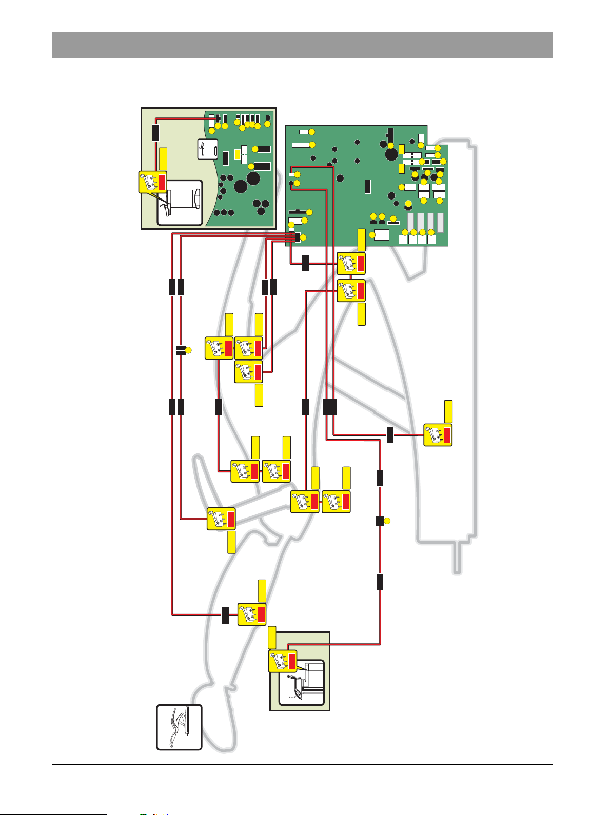
In the treatment center there are several CAN networks.
Thestandard CAN runs all of the control units for the treatment center, software updates and service support.
The S CAN runs only PC software functions for the user interface.
The motor CAN runs all commands for controlling the motorsM1 / M2 / M3 from theNSA board to the three DCFU boards.
After the treatment center is switched on, all components and software are queried and displayed in the set-up dialog. If the
connection fails during operation, the unit must be switched on again.
SET-UP key
C
> 2s
If an installed component is missing here, this board and the CAN connection to the user interface (NAKboard) must be
checked.
Each node that loses its standard CAN connection to the central error memory in the NSA board flashes cyclically 2x at its
error LED. -> Check the CAN bus.
In each CAN network there are 2x 120-Ohm resistors, that, measured in parallel on the CAN line, result in 60 Ohms. If you
measure 120 Ohms on the CAN line with an Ohm meter (when the dental treatment unit is switched off), there is a disruption
in the line.
In the case of a disruption, measure the connections between the connectors.
For example:
Check CAN
+
: NSA board, X1.5 to NAJboard X22.5:
0 - 3 Ohm = OK
00 Ohm = line disruption
240 Ohm = line disruption CAN+ but CAN- is OK
3 – 6 D 3509.076.01.01.02 07.2008
61 94 448 D 3509

3 Important information
3.3 CAN BUS wiring diagram
Standard CAN
3 33
5 45
NHE
CAN + CAN + CAN + CAN +
120
W
CAN - CAN - CAN - CAN -
SDI SDI
X4
YE YE YE YE YE YERD
GN GN GN GN GN GNBU
NSA NSC
X3X3 X1 X1 X1X22X4
A3
5 5 A3 A35555
A23 3 A2 A23333
B3
X4
B3
X4
X3 X3
A5 9
A4 7
A3
BU
A3
NSK NWE NSB HF
5
X2
YE
5
X16
YE
5
5
X32
Speed CAN
X31 X15 X31
NSA NAJ NAK
120
W
3
GN
3
GN
3
3
3
5
X5
YE BU OG
GN RD GNGY
3
5
X5
X6
X8
X8
4
3
4 mm Isolation
NAC / NAL
3
4
3
4
3
5
X32
B1
B2
X2
+
bеЦдблЬ
3
NSA
120
CAN +
W
CAN -
X1
RD RDPK
BK BUGY
SDI
NAJ NAK
X1X1X22
A5A5999
A4A4777
Motor CAN
NSA
DCFU
Motor-CAN + Motor-CAN + Motor-CAN +
RD YE
BU GN
Motor-CAN - Motor-CAN - Motor-CAN -
22
120
W
33
X10
2
3
7
120
W
6
120
W
DCFU
Motor-CAN +
2
3
Motor-CAN -
DCFU
2
3
M2
X4
YE
GN
X4X29X4
M3M1
61 94 448 D 3509
D 3509.076.01.01.02 07.2008
3 – 7

3 Important information
Patient chair
3.4
3.4.1 Stand-alone installation function
To operate the chair in stand-alone mode, the installation connector must be connected to the SDI connector of the assistant
element (on the chair). This connector closes off the CAN, simulates the safety switch in the assistant element and a bridge
lets the NSA board detect the connector.
If the patient chair does not find any NAJ board while booting, the four-way switch functions on the foot control like a fourway foot switch. If the four-way foot switch and/or tilt component switch are present as options, these will function to support
the set-up phase and operate the patient chair without the dentist element/assistant element.
Once the NAJ board is detected, patient chair travel will be carried out only with "approval of the NAK board".
During movement of the patient chair communication between the NSA and NAK boards will be monitored. If the communication is disrupted, the patient chair travel will also be disrupted or not started at all.
3.4.2 DCFU motor control
In the DCFU board, the motor parameters and motor allocation/addressing are stored for the motor to be activated.
There are two types of motor: one large motor (lifting motor) and 2 small motors (for inclination and backrest).
After the replacement of a DCFU board, the NSA board determines via the "reference travel" function which DCFU board is
connected to which motor and will transmit the corresponding motor parameters.
During the reference travel, the motors are moved slowly to the end positions and the software of the NSA board stores those
positions.
During operation, whenever a reference point is crossed via a light barrier at X5, the calculated position is compared with the
actual position and corrected.
3.4.3 Safety switches (For the locations of the safety switches see Section 1.6, Safety switches)
Safety switch Backrest
SS_RL: S10 > L332 > NSA X14.B4 (A4 = SS-GND)
LED: NSA / V402 (Yellow) / SS code / Flashes 8x
Safety switch, footrest
SS_FA: S9 > L334 > NSA X14.B3 (A3 = SS_GND)
LED: NSA / V402 (Yellow) / SS code / Flashes 7x
3 – 8 D 3509.076.01.01.02 07.2008
61 94 448 D 3509

Safety switch, rear cover panels, right/left
Elevation frame rear, right/left
Elevation frame front, right/left
SS_HR: S1, S2, S3, S4 > L317 > NSA X12.2 (X12.1 = SS-GND)
LED: NSA / V402 (Yellow) / SS code / Flashes 4x
Safety switches on manual switch bar rear/front, right/left
SS_HL: S5, S6, S7, S8 > L331 > NSA X14.B2 (A2 = SS-GND)
LED: NSA / V402 (Yellow) / SS code / Flashes 6x
3 Important information
bеЦдблЬ
3
Safety switch, armrest
SS_AL: S11 > L342 > X13 > L335 > NSA X14.B6 (A6 = SS-GND)
LED: NSA / V402 (Yellow) / SS code / Flashes 9x
Safety switch, assistant element
SS_HE: S14 > L235 > X2-SDI > L333 > NSA X13.2 (X13.1 = SS-GND)
61 94 448 D 3509
D 3509.076.01.01.02 07.2008
3 – 9

3 Important information
Safety switch, cuspidor
SS_MB: S13 > L218 > NWE X20.2 (X20.1 = SS-GND)
LED: NWE / SS_SP (Yellow) / ON
LED: NSA / V402 (Yellow) / SS code / Flashes 3x
3 – 10 D 3509.076.01.01.02 07.2008
61 94 448 D 3509

TENEO
4 Service area

4 Service area
Clean
Setup
Service area of the user interface
4.1
Entering the service area:
1. Hold down the "Setup" fixed key (>2 seconds). Six set-up programs will be offered for your selection.
2. To open one, touch the "Service Area" key. The service area will appear.
3. Touch the arrow key to get to the next screen.
C
1.
> 2s
2.
Meaning of the individual keys
Start LED and keyboard test on the user interface. By pressing the keys on the discrete keyboard, the corresponding
function LEDs can be switched on and off. When you press "Clean", the 4 cursor LEDs are also activated.
Emptying of the mixing tank
Chair reference path
Restoration of the factory settings
Amalgam test key for the alarm tone and amalgam indicator
Emptying of the disinfectant tank
Emptying of the flushing tank
Approach packaging position
Service info / Service code lists
Maintenance interval display and reset
3.
Dental treatment center information on design versions and installed options
Back
Set opening time for cuspidor valve
61 94 448 D 3509
4 – 2 D 3509.076.01.01.02 07.2008

4.2 Dental treatment center information
After you press the "Info" key, the configuration screen will appear.
4.2.1 Dentist element configuration INFO
Press the "Dentist Element" key.
The option is available if there is an orange frame around the option.
4 Service area
bеЦдблЬ
4
NAK: HW 0.0.0 - SW 0.5 Hardware and software version for the NAK board
NAKC: Operating system NAK version, HW version NAK processor module
NAJ: HW 0.0.0 - SW 0.0 Hardware and software version of the NAJ board
NAC: HW 0.0.0 - SW 0.0 Hardware and software version of the NAC board
HF: HW 0.0 - SW 0.0 Hardware and software version of the HF board
NAL: HW 0.0 - SW 0.0 Hardware and software version of the NAL board
X-ray image viewer
Spray water heater
3. Burr drive
4. Burr drive
Intraoral camera
k~`ä
NaCl pump
Ultrasound
61 94 448 D 3509
D 3509.076.01.01.02 07.2008
Sirotom
4 – 3

4 Service area
4.2.2 Assistant element configuration INFO
Press the "Assistant Element" key.
The option is available if there is an orange frame around the option.
NHE: HW 0.0.0 - SW 0.0 Hardware and software version of the NHE board
Sprayvit
Curing light
3. Suction hose
eóÇêç
Hydrocolloid connection
4.2.3 Patient chair configuration INFO
Press the "Patient Chair" key.
The option is available if there is an orange frame around the option.
NSA: HW 0.0.0 - SW 0.0 Hardware and software version of the NSA board
NSK: HW 0.0.0 - SW 0.0 Hardware and software version of the NSK board
NSB: HW 0.0.0 - SW 0.0 Hardware and software version of the NSB board
Motor-driven headrest
Active lumbar support function
Massage function
Four-way foot switch
61 94 448 D 3509
4 – 4 D 3509.076.01.01.02 07.2008

4.2.4 Water unit configuration INFO
Press the "Water Unit" key.
The option is available if there is an orange frame around the option.
NWE: HW 0.0.0 - SW 0.0 Hardware and software version of the NWE board
X-ray image viewer
Tumbler water heater
4 Service area
bеЦдблЬ
4
^ã~äÖ
aблбеСK
Amalgam separator
Operating light
Automatic tumbler filling
Disinfection system
Motor-driven cuspidor
Without frame: No cuspidor
Without frame: Cuspidor without motor available
Air/water separation
Dürr wet suction system
Automatic separator
61 94 448 D 3509
D 3509.076.01.01.02 07.2008
4 – 5

4 Service area
Clean
Setup
Reading out service codes
4.3
1. Hold down the "Setup" fixed key (>2 seconds). Six set-up programs will be offered for your selection.
2. To open one, touch the "Service Area" key. The service area will appear.
3. After you press the error storage key, the service code lists will appear..
C
1.
> 2s
3.
2.
4 – 6 D 3509.076.01.01.02 07.2008
61 94 448 D 3509

4.4 Maintenance display
After you press the operating data key, the screen for the maintenance intervals appears.
• This displays the number of days until maintenance must be performed.
4 Service area
bеЦдблЬ
4
61 94 448 D 3509
D 3509.076.01.01.02 07.2008
4 – 7

4 Service area
Service support with the PC
4.5
The program "Sirona Dental Unit Management Console" (Sirona DUMC) is available to support the service engineers.
This program provides the following services:
• Service management
(Readout and storage of service information)
• Data management
(readout, storage, reloading of data in the treatment station, if for example boards must be replaced or if user-specific settings are to be transferred from one dental treatment center to another)
• Firmware download
(Determine the version of a dental treatment center, download the new firmware, synchronize the firmware to a valid release, e.g. after individual boards have been replaced).
For more information about this program, please refer to the DUMC user manual: 61 94 489 D3509
4 – 8 D 3509.076.01.01.02 07.2008
61 94 448 D 3509

TENEO
5 Points to observe when replacing ...

5 Points to observe when replacing ...
Clean
Setup
5.1 ... Boards
Before replacing the NAJ, NSA, NWE, NHE andNAK boards, you must back
up the data with the DUMC program.
1. Back up data (all of it)
2. Replace board
3. Download firmware
4. Restore data if necessary
CAUTION
Before any boards are replaced, the treatment center must be switched OFF!
EIN
AUS
5.1.1 ... DCFU board in the patient chair
DCFU
2.
• After the DCFU board is replaced, a reference run must be carried out.
C
Clean
1.
> 2s
3.
To do this, push the key in the service area of the user interface on the dentist element .
61 94 448 D 3509
5 – 2 D 3509.076.01.01.02 07.2008

5 Points to observe when replacing ...
NSK
5.1.2 ... NSA board in the patient chair
• After the NSA board is replaced, a reference run must be
carried out, as the reference for the travel track is stored
here.
• To do this, press the key in the service area of the user interface on the dentist element.
bеЦдблЬ
NSA
• Check the date and time in the Set-up program.
5.1.3 ... NSK board in the patient chair
• After the NSK board is replaced, a reference run must be
carried out, as the reference for the headrest is stored here.
• To do this, press the key in the service area of
the user interface on the dentist element.
5
61 94 448 D 3509
D 3509.076.01.01.02 07.2008
5 – 3

5 Points to observe when replacing ...
2
NAJ
X10
5.1.4 ... HF+ board in the dentist element
• The jumper setting of X10 on the new HF+ module must be
at C1.
X7
+
HF
J1
J11
J13
• Check whether the bridge to X7.2 / X7.3 is present.
5.1.5 ... NAJ board in the dentist element
• When replacing an NAJ board, the dongles (J11, J12, J13)
of the defective board must be reconnected to the new
board.
• The jumper setting of S1 on the discarded board must be used.
1
S
S101
S100
5.1.6 ... NHE board in the assistant element
The switch setting of S100 (S-CAN) and S101 (supplementary
holder) must be transferred from the discarded NHE to the new
NHEboard.
NHE
5.1.7 ... NWE board in the water unit
i
NOTE
When replacing the board, cover the ventilation slits over the
power supply unit so that no screws fall into it.
NWE
61 94 448 D 3509
5 – 4 D 3509.076.01.01.02 07.2008

5 Points to observe when replacing ...
1
2
5
6
L247
KL3
+36V
GND
A
C
5.1.8 ... NAR board in the RÖBI
CAUTION
During the replacement of the NAR board, reconnect the lines
NAR
1
8
from the old to the new board directly so that none of the lines
are incorrectly connected.
K
L1
KL2
3
4
7
8
bеЦдблЬ
5
61 94 448 D 3509
D 3509.076.01.01.02 07.2008
5 – 5


TENEO
6 PC connection / Networking

6 PC connection / Networking
6.1
You'll find further information on connecting the dental treatment center to a
practice network in:
"User Manual - DUMC" SN: 6194489
Section: For components in a network
and
configuration with regard to the network address, please see
"Operating Instructions -TENEO" SN: 6193549
Section: Operation and> configuration of the dental treatment center -> Configuring network connections.
Connection of a dental treatment center to the
practice network
6 – 2 D 3509.076.01.01.02 07.2008
61 94 448 D 3509

6 PC connection / Networking
6.2 PC control via SIUCOM plus
6.2.1 Control of PC programs via the treatment center
SIUCOM plus enables you to control PC programs via the Sirona treatment
center TENEO. The PC functions can be operated via the user interface of the
treatment center (touch screen) or the system foot control.
6.2.2 Ethernet connection is required.
This is achieved through communication of the treatment center with the PC
via the Ethernet interface and the practice network. The function codes generated by specific operations in the treatment center are assigned to the
desired PC functions in the SIUCOM program. Under certain circumstances
it is therefore possible to start, terminate and control PC applications.
6.2.3 Third-party programs can also be controlled in this manner.
The SIUCOM plus PC program provides the Sirona SIUCOM plus interface
for operating functions inside PC programs of other manufacturers.
The operating functions provided by the manufacturer of the SIUCOM pluscapable PC application can thus be triggered from the treatment center.
For further information, please see "Installation and Configuration - SIUCOM
plus" SN: 6084367.
bеЦдблЬ
6
61 94 448 D 3509
D 3509.076.01.01.02 07.2008
6 – 3


tÉ=кЙлЙкоЙ=нЬЙ=кбЦЬн=нз=г~вÉ=~åó=~äíÉê~íáзел=пЬбЕЬ=г~у=ДЙ=кЙимбкЙЗ=ЗмÉ=íç=íÉÅÜåáÅ~ä=áãйкзоЙгЙенëK
«=páêçå~=aÉåí~ä=póëíÉãë=dãÄe=OMMU i~åÖì~ÖÉW=båÖäáëÜ= mкбенЙЗ=бе=dЙкг~еу
a=PRMVKMTSKMNKMNKMO= MTKOMMU ûKJkêKW= MMM=MMM fгйкбг¨=Éå=^ääÉã~ÖåÉ
páêçå~=aÉåí~ä=póëíÉãë=dãÄe
få=íÜÉ=rp^W få=`~å~Ç~W
c~Дкбвлíê~ëëÉ=PN
SQSOR=_ЙелЬЙбг
dÉêã~åó
ïïïKëáêçå~KÅçã
páêçå~=aÉåí~ä=póлнЙгл=ii`
QUPR=páêçå~=aêáîÉI=pìáíÉ=NMM
`Ь~кдзннЙI=k`=OUOTP
rp^
páêçå~=`~å~Ç~
PORM=oáÇÖÉï~ó=aêáîÉ=J=råáí=R
jáëëáëë~ìÖ~I=låí~êáç=iRi=RvS
`~å~Ç~
lêÇÉê=kçK
SN=VQ=QQU=a=PRMV
 Loading...