

Page 1
OPERATINGINSTRUCTIONS
CHANNEL
SELECTOR
TONE MODE
A/B
PHONES
SPEAKER
TUNING/PRESET
TEST TONE VIDEO LABEL
ROOM2 FEED
AUDIO/VIDEO SURROUND RECEIVER
R-963
MULTI CONTROL
DYNAMIC
RANGE
T/P MODE
MASTER VOLUME
ON/STANDBY
STANDBY
POWER
BAND CINEMA EQ
MEMO/ENTER
ON / OFF
S-VIDEOOPTICAL IN VIDEO L - AUDIO - R
INPUT SELECTOR
AUDIO VIDEO DIGITAL/ANALOGEXTRA SURR.
6.1/7.1
STEREO
SOURCE
DIRECT
TAPE MON. 7.1CH DIRECT DECODING
SURROUND MODE
VIDEO 5
MULTI ROOM
REMOTE SENSOR
R-963
AUDIO/VIDEO SURROUND RECEIVER
Page 2
2
Introduction
Congratulations on Your Purchase!
Your new high fidelity receiver is designed to deliver
maximum enjoyment and years of trouble free service.
Please take a few moments to read this manual
thoroughly. It will explain the features and operation of
your unit and help ensure a trouble free installation.
Please unpack your unit carefully. We recommend that
you save the carton and packing material. They will be
helpful if you ever need to move your unit and may be
required if you ever need to return it for service. Your unit
is designed to be placed in a horizontal position and it is
important to allow at least two inches of space behind
your unit for adequate ventilation and cabling
convenience.
To avoid damage, never place the unit near radiators, in
front of heating vents, in direct sunlight, or in excessively
humid or dusty locations. Connect your complementary
components as illustrated in the following section.
CAUTION : TO REDUCE THE RISK OF
ELECTRIC SHOCK, DO NOT
REMOVE COVER (OR BACK).
NO USER-SERVICEABLE PARTS
INSIDE. REFER SERVICING TO
QUALIFIED SERVICE PERSONNEL.
CAUTION
RISK OF ELECTRIC SHOCK
DO NOT OPEN
This symbol is intended to alert the user to the
presence of uninsulated "dangerous voltage"
within the product's enclosure that may be of
sufficient magnitude to constitute a risk of
electric shock to persons.
This symbol is intended to alert the user to the
presence of important operating and
maintenance (servicing) instructions in the
literature accompanying the appliance.
To reduce the risk of fire or electric shock, do not expose
this appliance to rain or moisture.
Caution : Do not block ventilation openings or stack
other equipment on the top.
FOR U.S.A
Note to CATV System Installer: This reminder is
provided to call the CATV system installer's attention
to Article 820-40 of the NEC that provides guidelines
for proper grounding and, in particular, specifies that
the cable ground shall be connected to the
grounding system of the building, as close to the
point of cable entry as practical.
FCC INFORMATION
This equipment has been tested and found to
comply with the limits for a Class B digital device,
pursuant to Part 15 of the FCC Rules. These limits
are designed to provide reasonable protection
against harmful interference in a residential
installation. This equipment generates, uses and can
radiate radio frequency energy and, if not installed
and used in accordance with the instructions, may
cause harmful interference to radio communications.
However, there is no guarantee that interference will
not occur in a particular installation. If this equipment
does cause harmful interference to radio or
television reception, which can be determined by
turning the equipment off and on, the user is
encouraged to try to correct the interference by one
or more of the following measures:
Reorient or relocate the receiving antenna.
Increase the separation between the equipment
and receiver.
Connect the equipment into an outlet on a circuit
different from that to which the receiver is
connected.
Consult the dealer or an experienced radio/TV
technician for help.
CAUTION : Any changes or modifications in
construction of this device which are not expressly
approved by the party responsible for compliance
could void the user's authority to operate the
equipment.
WARNING
UNPACKING AND INSTALLATION
Caution regarding placement
(Except for U.S.A and Canada)
To maintain proper ventilation, be sure
to leave a space around the unit (from
the largest outer dimensions including projections)
equal to, or greater than, shown below.
Left and right panels: 5 cm
Rear panel: 10 cm
Top panel: 20 cm
ENGLISH
Page 3
3
READ THIS BEFORE OPERATING YOUR UNIT
FOR U.S.A AND CANADA .......................................120 V
Units shipped to the U.S.A and Canada are
designed for operation on 120 Volts AC only.
Observe all safety precautions for use of a polarized
AC plug. However, some products may be supplied
with a non polarized plug.
CAUTION: To prevent electric shock, match wide
blade of plug to wide slot, insert fully.
FOR YOUR SAFETY
FOR EUROPE AND AUSTRALIA ..........230V/240V
Units shipped to Australia are designed for operation
on 240 V AC only.
To ensure safe operation, the three-pin plug supplied
must be inserted only into a standard three-pin
power point which is effectively earthed through the
normal household wiring. Extension cords used with
the equipment must be three-core and be correctly
wired to provide connection to earth.
Improper extension cords are a major cause of
fatalities. The fact that the equipment operates
satisfactorily does not imply that the power point is
earthed and that the installation is completely safe.
For your safety, if in any doubt about the effective
earthing of the power point, consult a qualified
electrician.
PAN-EUROPEAN UNIFIED VOLTAGE
All units are suitable for use on supplies 230-240 V
AC.
FOR YOUR SAFETY
FOR OTHER COUNTRIES ........................... 115 V/230 V
Units shipped to countries other than the above
countries are equipped with an AC voltage selector
switch on the rear panel. Refer to the following
paragraph for the proper setting of this switch.
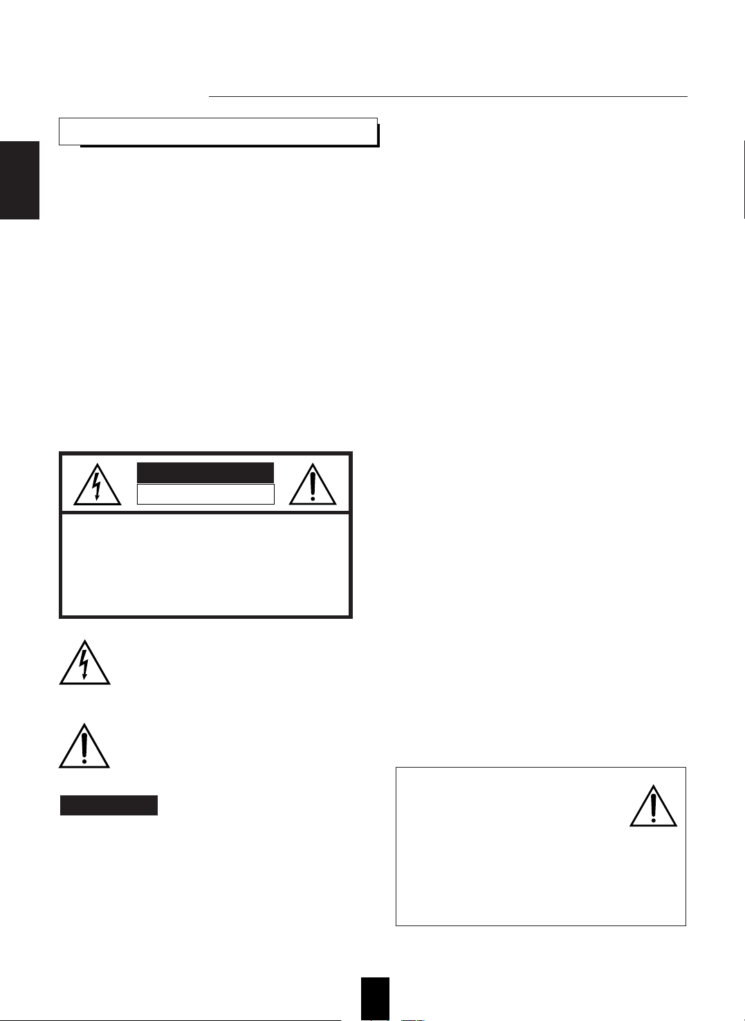
AC VOLTAGE SELECTION
This unit operates on 115/230 V AC. The AC voltage
selector switch on the rear panel is set to the voltage
that prevails in the area to which the unit is shipped.
Before connecting the power cord to your AC outlet,
make sure that the setting position of this switch
matches your line voltage. If not, it must be set to
your voltage in accordance with the following
direction.
AC voltage selector switch
Move switch lever to match your line voltage with a
small screwdriver or other pointed tool.
FOR YOUR SAFETY
AC 230 V AC 115 V
ENGLISH
Page 4

4
CONTENTS
Introduction
UNPACKING AND INSTALLATION ....................................................................................................... 2
READ THIS BEFORE OPERATING YOUR UNIT................................................................................... 3
System Connections........................................................................................................................................ 5
Front Panel Controls.................................................................................................................................... 10
Universal Remote Controls
DIGI LINK SYSTEM REMOTE CONTROLS ......................................................................................... 11
OPERATING COMPONENTS WITH REMOTE CONTROL................................................................. 13
REMOTE CONTROL OPERATION RANGE.......................................................................................... 13
LOADING BATTERIES............................................................................................................................ 13
ENTERING A SETUP CODE ................................................................................................................... 14
ADDITIONAL INFORMATION ON REMOTE COMMAND CODES.................................................. 16
ROOM 2 Remote Controls
REMOTE CONTROL OPERATION RANGE.......................................................................................... 17
LADING BATTERIES .............................................................................................................................. 17
Operations
LISTENING TO A PROGRAM SOURCE................................................................................................ 18
SURROUND SOUND................................................................................................................................ 21
ENJOYING SURROUND SOUND........................................................................................................... 24
LISTENING TO RADIO BROADCASTS ................................................................................................ 28
RECORDING ............................................................................................................................................. 30
DIGITAL AUDIO RECORDING WITH MD RECORDER..................................................................... 31
OTHER FUNCTIONS................................................................................................................................ 32
ROOM 2 SOURCE PLAYBACK .............................................................................................................. 34
Using the OSD
CURRENT STATUS DISPLAY................................................................................................................ 35
OSD Menu Settings....................................................................................................................................... 35
SETTING THE POWER AMP ASSIGN................................................................................................... 37
SETTING THE SPEAKER SETUP........................................................................................................... 38
SETTING THE FUNCTION SELECT ......................................................................................................41
SETTING THE SURROUND SETUP.......................................................................................................47
SETTING THE CH LEVEL TRIM............................................................................................................ 49
SETTING THE ROOM 2 FEED SETUP................................................................................................... 50
Troubleshooting Guide ................................................................................................................................52
Specifications.................................................................................................................................................. 53
ENGLISH
Page 5
5
System Connections
Please be certain that the receiver is unplugged from the AC outlet before making any connections.
Be sure to connect the white RCA pin cords to the L(left) and the red RCA pin cords to the R(right) jacks when making connections.
Change the position of the FM indoor antenna until you get the best reception of your favorite FM stations.
A 75Ω outdoor FM antenna may be used to further improve the reception.
Disconnect the indoor antenna before replacing it with the outdoor one.
Place the AM loop antenna as far as possible from the receiver, TV set, speaker cords and the AC input cord and set it to a direction
for the best reception.
If the reception is poor with the AM loop antenna, an AM outdoor antenna can be used in place of the AM loop antenna.
Make connections firmly and correctly. If not, poor connections can cause loss of sound, noise or damage to the receiver.
If the electricity fails or the AC input cord is left unplugged for about 2 weeks, the memorized contents will be lost.
Should this happen, memorize them again.
CENTER
SPEAKER
FRONT B SPEAKERS
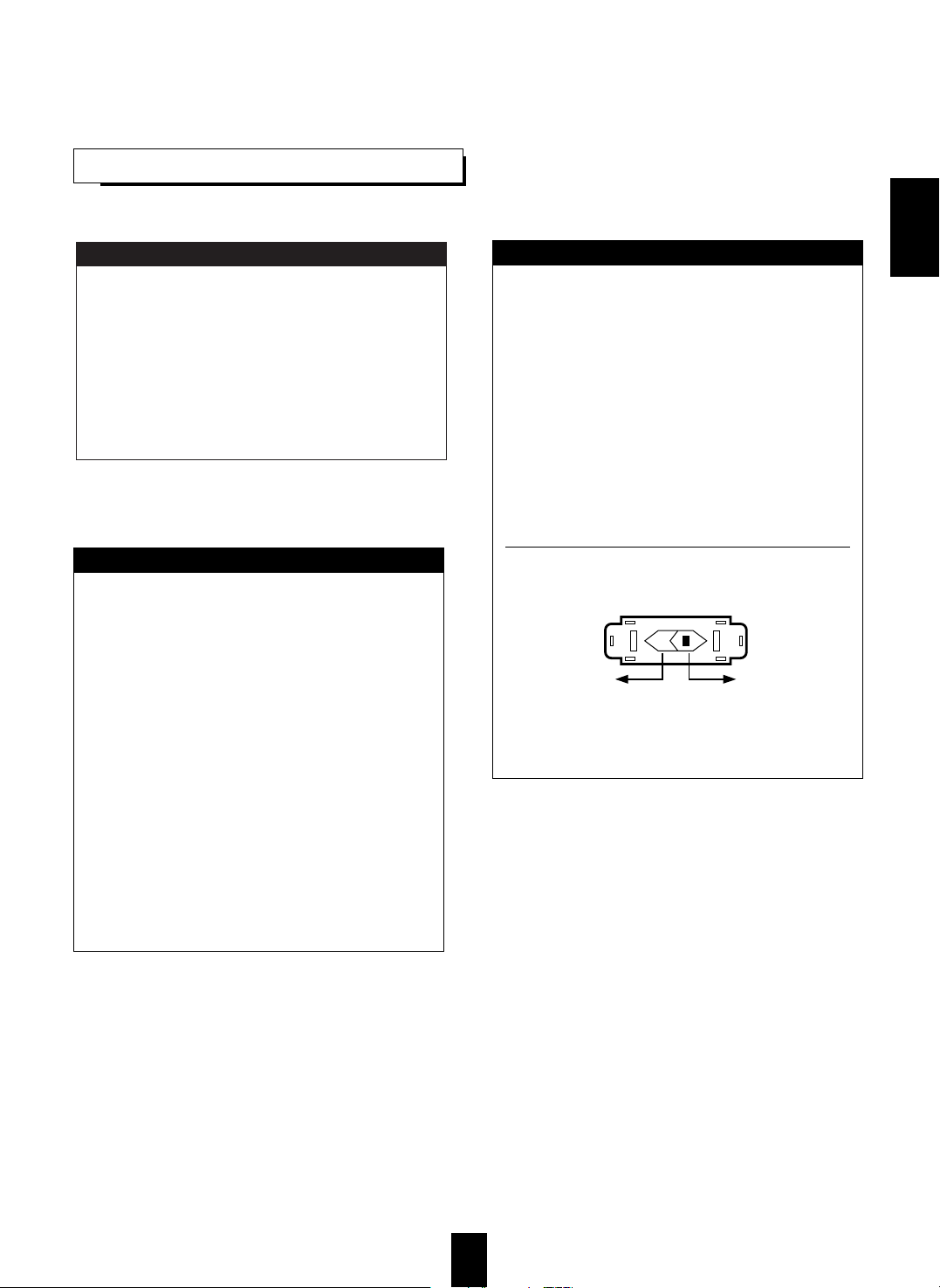
■ CONNECTING ANTENNAS
FM
■ CONNECTING AUDIO COMPONENTS
FM
(INDOOR ANTENNA)
(OUTDOOR ANTENNA)
SUPPLIED ADAPTOR
300 ohm
feeder
• Use these jacks to connect the corresponding analog audio and video outputs of a DVD player or external decoder, etc. that has 5.I or 7.1
channel audio and video outputs.
• In case of 5.1 channel outputs, do not connect these SURROUND BACK inputs to your component. (For details, refer to the operating
instructions of the component to be connected.)
• The AUX jacks may be connected to an additional audio component such
as CD player or tape deck, etc.
• Connect the TAPE MONITOR IN/OUT jacks to the PLAY(LINE OUT)
/REC(LINE IN) jacks of tape deck, MD recorder or CD recorder.
• The TAPE MONITOR IN/OUT jacks may also be connected to the
LINE OUT/IN jacks of an optional graphic equalizer.
Note :
• Do not connect the turntable with MC type cartridge directly.
If so, use a separate head amplifier or step-up transformer.
PLAY(LINE OUT)
REC(LINE IN)
SURROUND CH OUT
SURROUND BACK CH OUT
SUBWOOFER CH OUT
CENTER CH OUT
VIDEO OUT
S-VIDEO OUT
FRONT CH OUT
CD player
POWER
REMOTE SENSOR
PROGRAM/REVIEW
RANDOM REPEAT
OPEN/CLOSE
PHONES LEVEL
PHONES
MIN MAX
ON/OFF
MULTIPLE COMPACT DISC PLAYER CDC-5080R
12 3 4 5
GRAPHICSPEAKDELETE EDIT
SCENETRACK
INDEXSTEP
AB
V-CDPBCREVERT PROG AUTO RANDOMREPEATALL1DISCS
123
456
789
101112
131415
MPXINTROA< >B
■ CONNECTING 7.1CH DIRECT INPUT
Additional
audio component
Tape deck or
MD recorder
Decoder with 5.1
or 7.1 channel output
Turntable with MM type cartridge
AM loop antenna
ENGLISH
Page 6
6
■
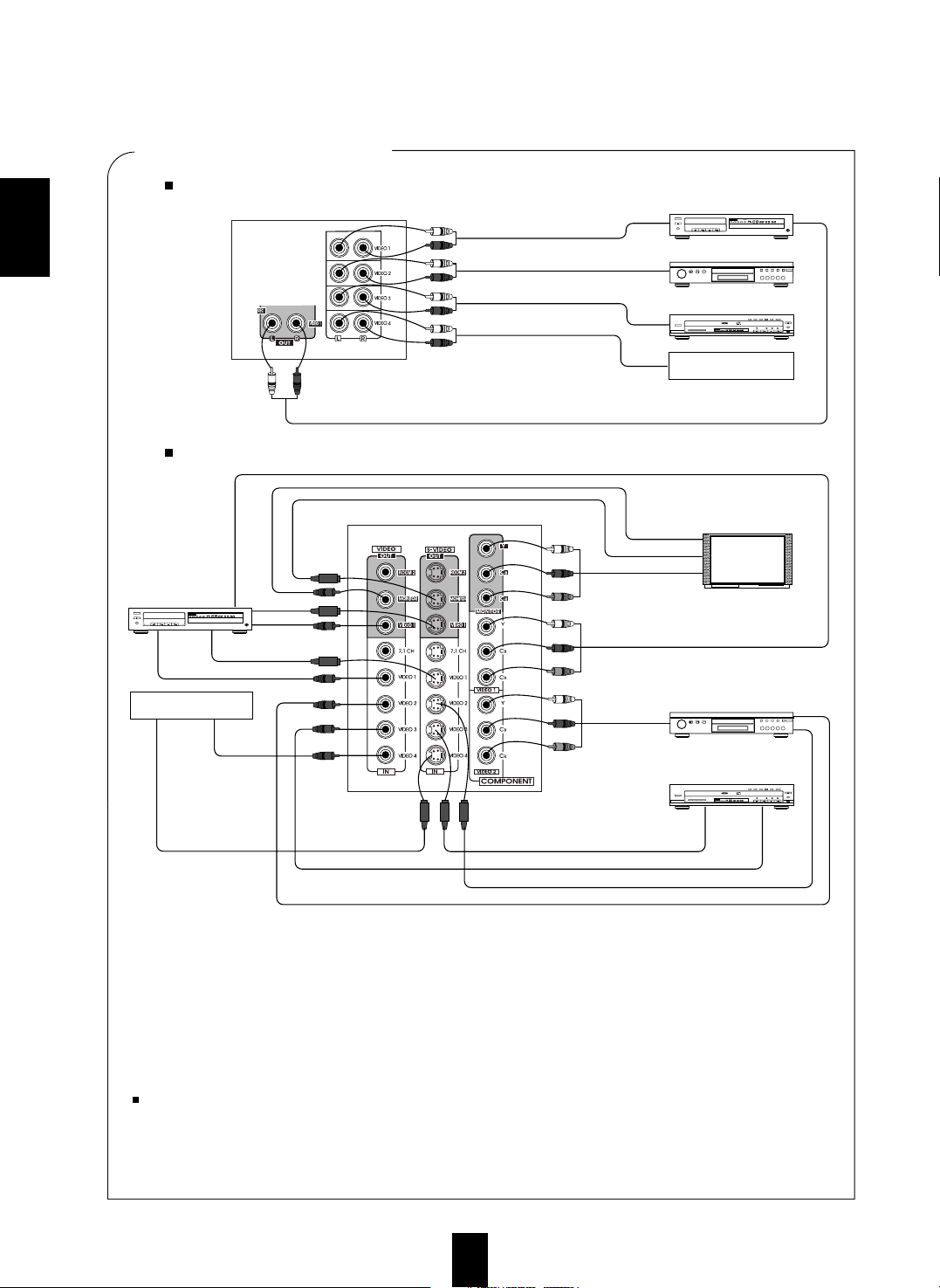
CONNECTING VIDEO COMPONENTS
POWER
OPEN/CLOSE
PHONES LEVEL
PHONES
MIN MAX
ON/OFF
MULTIPLE COMPACT DISC PLAYER CDC-5080R
1 2 3 4 5
GRAPHICSPEAK DELETEEDIT
SCENETRACK
INDEXSTEP
AB
V-CDPBCREVERT PROGAUTO RANDOM REPEATALL1DISCS
123
456
789
101112
131415
MPXINTROA< >B
Video deck or additional
video component
POWER
OPEN/CLOSE
PHONES LEVEL
PHONES
MIN MAX
ON/OFF
MULTIPLE COMPACT DISC PLAYER CDC-5080R
1 2 3 4 5
GRAPHICSPEAK DELETEEDIT
SCENETRACK
INDEXSTEP
AB
V-CDPBCREVERT PROGAUTO RANDOM REPEATALL1DISCS
123
456
789
101112
131415
MPXINTROA< >B
Video deck or
additional video
component
• There are three kinds of video jacks (COMPONENT, S, normal (composite)) for connecting video components. Connect them to the
corresponding VIDEO jacks ( VIDEO 1~4) respectively according to their capability.
• The VIDEO 1 jacks may also be connected to a DVD recorder or other digital video recording component.
For details, refer to the operating instructions of the component to be connected.
• This unit incorporates COMPONENT as well as S and normal(composite) VIDEO jacks.
• For your reference, the excellence in picture quality is as follows: "COMPONENT" > "S" > normal(composite) "VIDEO".
• When making COMPONENT VIDEO connections, connect "Y" to "Y", "CB" to "CB" (or "B-Y", "PB") and "CR" to "CR"(or "R-Y",
"PR").
• Signals input into the COMPONENT VIDEO IN jacks will be output in only the MONITOR COMPONENT VIDEO OUT jacks.
• A signal input into the normal(composite) VIDEO IN jack will be output in the normal(composite) VIDEO OUT jacks and a signal
input into the S-VIDEO IN jack will be output in the S-VIDEO OUT jacks.
Notes :
• Neither on-screen display function nor video recording are available when using the COMPONENT VIDEO connections.
• When Sherwood DVD player such as V-756, etc. is connected to the DIGI LINK jack for system control, you should connect the DVD
player to the "VIDEO 2" jacks of this unit.
Because, if the PLAY button, etc. is pressed on the DVD player, the VIDEO 2 is automatically selected as an input source on this unit.
Then playback, etc. starts.
POWER
ON/OFF
MULTIPLE COMPACT DISC PLAYER CDC-5080R
DVD player
POWER
ON/OFF
MULTIPLE COMPACT DISC PLAYER CDC-5080R
DVD player
AUDIO OUT
AUDIO PLAY(OUT)
AUDIO OUT
AUDIO OUT
AUDIO REC(IN)
S-VIDEO OUT
VIDEO OUT
S-VIDEO OUT
VIDEO OUT
S-VIDEO OUT
VIDEO OUT
S-VIDEO IN
VIDEO IN
S-VIDEO OUT
VIDEO OUT
VIDEO IN
S-VIDEO IN
COMPONENT VIDEO IN
COMPONENT
VIDEO OUT
TV or additional
video component
LD player
POWER
12345
DISC SKIP
REMOTE SENSOR
PROGRAM/REVIEW
RANDOM REPEAT
OPEN/CLOSE
PHONES LEVEL
PHONES
MIN MAX
ON/OFF
MULTIPLE COMPACT DISC PLAYER CDC-5080R
5 DISC
PLAY EXCHANGE
Play 1 Exchange 4
AUTOMATIC DISC LOADING SYSTEM
12 34 5
GRAPHICSPEAKDELETE EDIT
SCENETRACK
INDEXSTEP
AB
V-CDPBCREVERTPROG AUTO RANDOMREPEATALL 1 DISC S
123
456
789
101112
131415
MPXINTROA< >B
Monitor TV
TV or additional
video component
Green
Blue
Red
Green
Blue
Red
Green
Blue
Red
COMPONENT VIDEO OUT
AUDIO IN/ OUT connections
VIDEO IN/OUT connections
This unit
This unit
ENGLISH
Page 7
7
CENTER
SPEAKER
FRONT B SPEAKERS
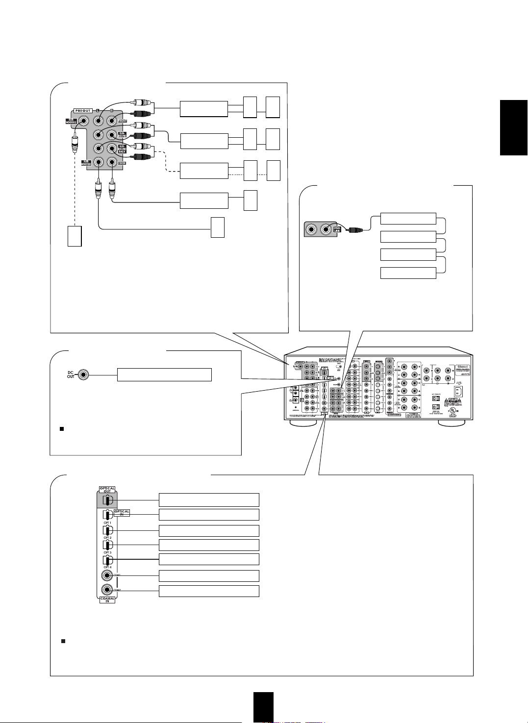
• The COAXIAL or the OPTICAL DIGITAL OUTs of the components
that are connected to CD, TAPE MONITOR and VIDEO 1-VIDEO 5
of this unit can be connected to these DIGITAL INs.
Notes :
• After making digital connections, be sure to match the DIGITAL INs
to the corresponding input source respectively. (For details, refer to
"When selecting the DIGITAL IN SETUP" on page 41.)
• A digital input should be connected to the components such
as LD player, CD player or DVD player, etc. capable of
outputting DTS, Dolby Digital or PCM format digital
signals, etc.
• If the component with OPTICAL IN jack is connected to
the OPTICAL OUT jack of this unit, you can record the
high quality sound of CDs, etc. without degradation.
• For details, refer to the operating instructions of the
connected component.
• When making the COAXIAL DIGITAL connection, be
sure to use a 75 Ω COAXIAL cord, not a conventional
AUDIO cord.
• All of the commercially available optical fiber cords cannot
be used for the equipment. If you have a question about the
suitability of a particular cord, please consult your dealer or
nearest service organization.
■ CONNECTING DIGITAL INs and OUT
■ CONNECTING SYSTEM CONTROL
■
CONNECTING DC OUT
• Use these jacks when adding additional amplifiers.
• Connect the PRE OUT jacks to the powered speakers or the power
amplifiers connected to speakers respectively.
• Only when enjoying 6.1 or 7.1 channel surround playback, make the
surround back connections between the audio equipment.
• To emphasize the deep bass sounds, connect a powered subwoofer.
• To enjoy deeper bass sounds, connect an additional powered subwoofer to
the SUBWOOFER 2 jack.
Front speakers
Power amplifier
Surround speakers
Power amplifier
Surround back speakers
Power amplifier
Front center speaker
Powered subwoofer
■ PRE OUT connections
Power amplifier
System
control
cord
Sherwood component
with DIGI LINK II or III
CD player
Tape deck
Graphic equalizer
DVD player
• Connect this jack to the DIGI LINK jack of the
external Sherwood component that uses the DIGI
LINK II or III remote control system.
• Connect a component that needs to be triggered by DC
under certain conditions(screen, power strip, etc.) (For
details, refer to the operating instructions of the
component to be connected.)
Note
• This output voltage (15 V DC) is for (status) control only,
it is not sufficient for drive capability.
Additional powered subwoofer
Component(such as an MD recorder,
CD recorder) with OPTICAL DIGITAL IN
Component to be triggered by DC
Component with OPTICAL DIGITAL OUT
Component with COAXIAL DIGITAL OUT
Component with OPTICAL DIGITAL OUT
Component with OPTICAL DIGITAL OUT
Component with OPTICAL DIGITAL OUT
Component with COAXIAL DIGITAL OUT
ENGLISH
Page 8
ENGLISH
8
CENTER
SPEAKER
FRONT B SPEAKERS
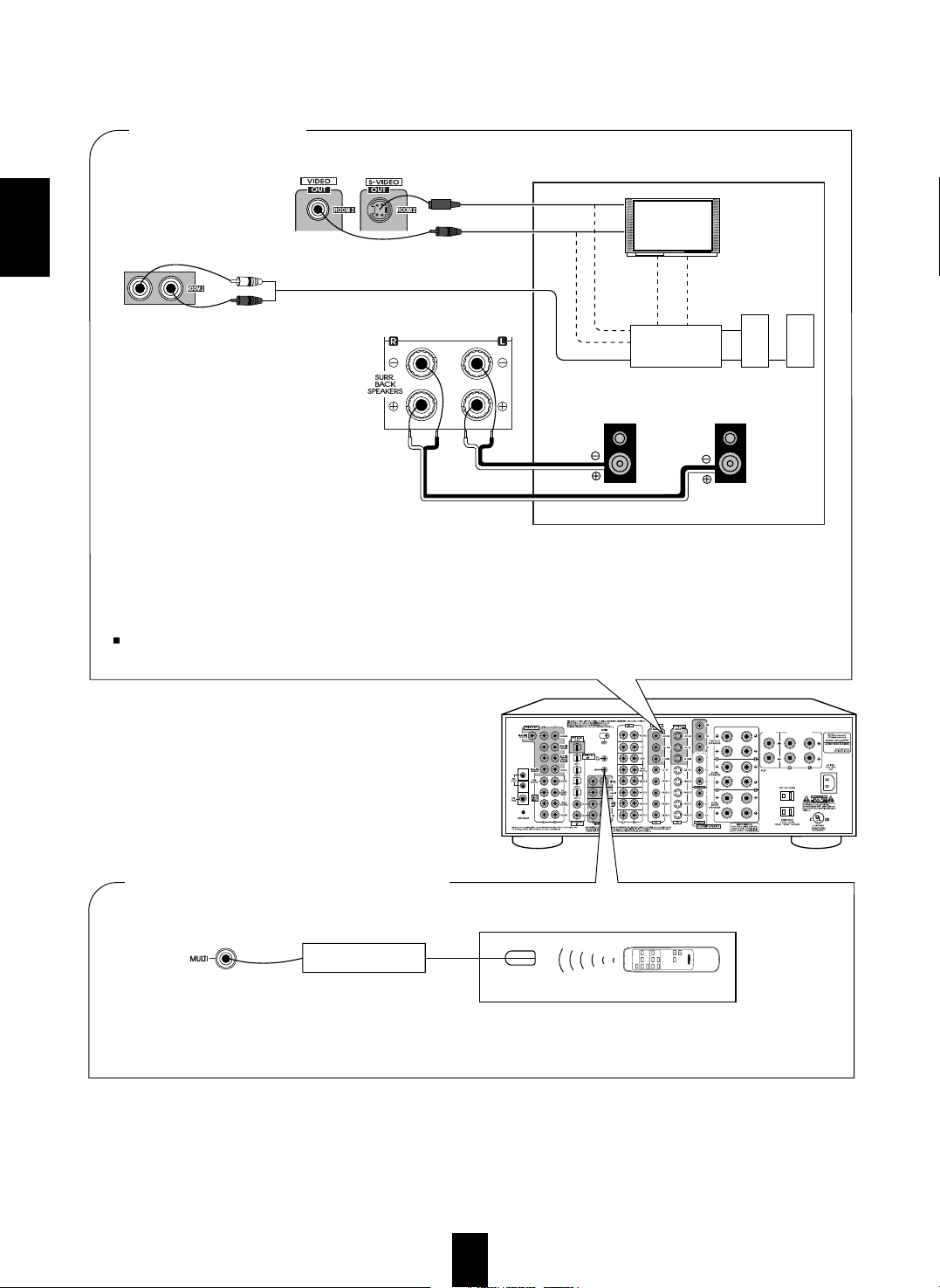
■ ROOM 2 connections
• To control this unit from a remote location, connect this jack to the output of the multi-room adaptor.
For information on the multi-room system kit, contact the Xantech corporation at 1-800-843-5465 or www.xantech.com.
VIDEO IN
S-VIDEO IN
VIDEO IN
S-VIDEO IN
Another room
AUDIO IN
• If another A/V receiver or integrated amplifier, etc. is connected to these jacks, you can play a different program source in another
room as well as one source in the main room at the same time.(For details, refer to "ROOM 2 SOURCE PLAYBACK" on page 34).
• However, in case that you do assign the power amplifier for the surround back channels to the ROOM 2 and install the speakers
connected to these channels in another room, you need not use the power amplifier to drive the speakers additionally in another
room. (For details, refer to "SETTING THE POWER AMP ASSIGN" on page 37.)
• When the multi-room system kit is connected, the ROOM 2 function is more convenient.
Note:
• To minimize hum or noise, use high quality connection cords.
■ CONNECTING MULTI-ROOM SYSTEM KIT
OUT
Another room
Adaptor
(Multi-room system kit)
IR receiver
(Multi-room system kit)
ROOM 2 remote
control unit
Monitor TV
A/V receiver
or amplifier
Speakers
or
Speakers
left
right
ROOM2
PHOTO CD
AUX
AUDIO
TUNER
OFF
VIDEO 1 VIDEO 2
VIDEO 4 VIDEO 5
MUTING
VOLUME
VIDEO
VIDEO 3
REMOTE CONTROL UNIT RM-103
Page 9
9
ENGLISH
CENTER
SPEAKER
FRONT B SPEAKERS
• These outlets are switched on(power-on
mode) and off(standby mode) according
to the power control as follows(Maximum
total capacity is 1A, 100W):
Standby mode – switched AC outlet off
Power-on mode – switched AC outlet on
■ SWITCHED AC OUTLETS
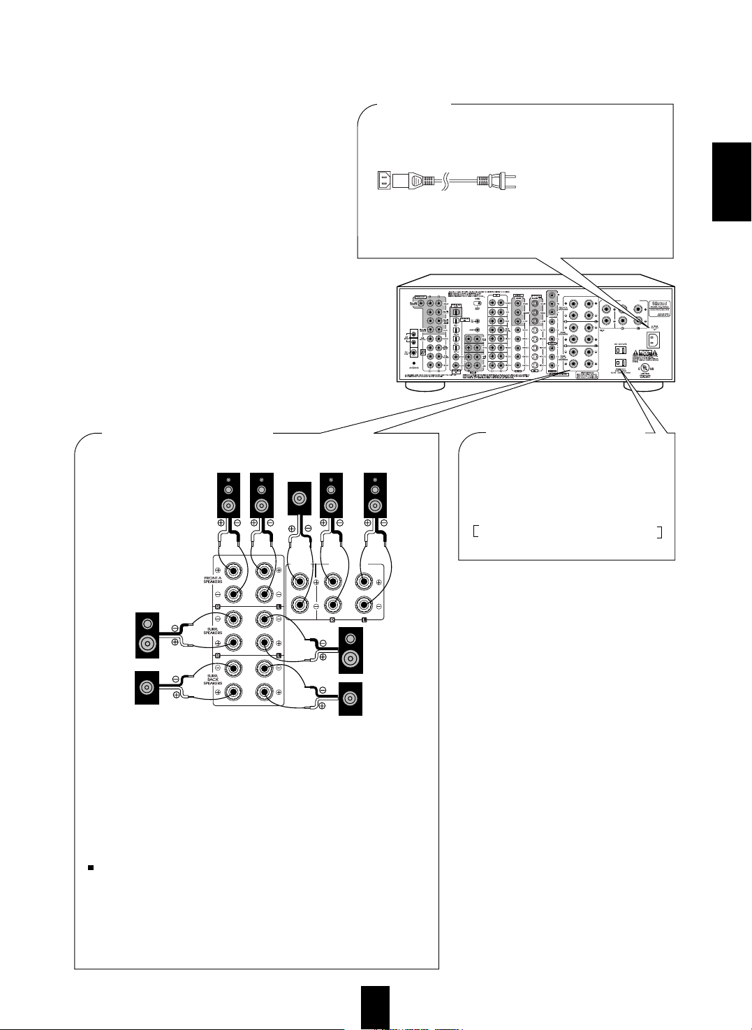
■ AC INLET
Plug the supplied AC input cord into this AC INLET and then
into the wall AC outlet.
To a wall AC
outlet.
• Do not use an AC input cord other than the one supplied with
this unit. The AC input cord supplied is designed for use with
this unit and should not be used with any other device.
• You can connect two sets of front speakers and can select front A or (and) B
speakers according to your taste.
• Never short circuit the + and - speaker wires.
• Be sure to connect speakers firmly and correctly according to the channel
(left and right ) and the polarity ( + and -).
• Only when enjoying either 6.1 or 7.1 channel surround playback, connect
either the surround back left speaker only or both of surround back speakers.
• If you assign the power amplifier for the surround back channels to the
ROOM 2, this receiver can drive the speakers in another room(ROOM 2).
(For details, refer to "ROOM 2 connections" on the previous page and
"SETTING THE POWER AMP ASSIGN" on page 37.)
Notes:
• For safe amplifier operation, in case of using either front A or front B
speakers, use all the speakers with impedance of over 6 Ω. However, in case
of using both front A and front B speakers, use only the front speakers with
impedance of over 12 Ω and other speakers with impedance of over 6 Ω.
• After installing the speakers, first set the connected speakers to the desired
before operating this receiver.(For details, refer to "SETTING THE
SPEAKER SETUP" on page 38.)
■ CONNECTING SPEAKERS
CENTER
SPEAKER
FRONT B SPEAKERS
left
right
Front B SpeakersFront A Speakers
left
right
Front
center
Surround
left
Surround
back left
Surround
right
Surround
back right
Page 10
ENGLISH
10
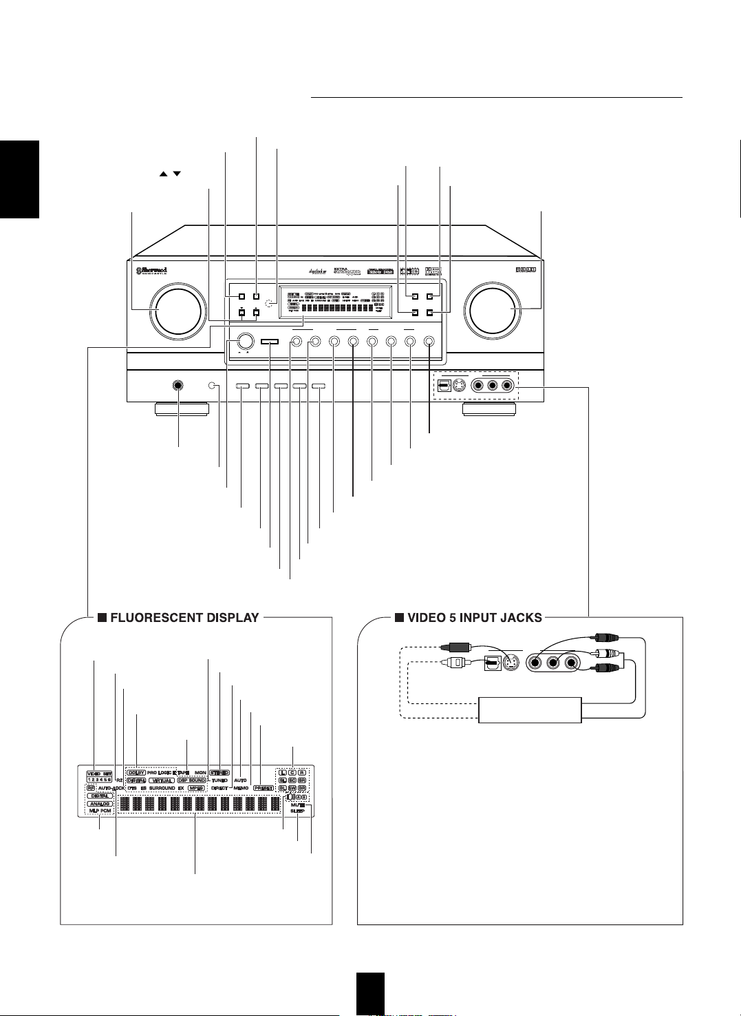
Front Panel Controls
S-VIDEO OUT
OPTICAL OUT
AUDIO OUT
VIDEO OUT
Additional video component
CHANNEL
SELECTOR
TONE MODE
A/B
PHONES
SPEAKER
TUNING/PRESET
TEST TONE VIDEO LABEL
ROOM2 FEED
AUDIO/VIDEO SURROUND RECEIVER
R-963
MULTI CONTROL
DYNAMIC
RANGE
T/P MODE
MASTER VOLUME
ON/STANDBY
STANDBY
POWER
BAND CINEMA EQ
MEMO/ENTER
ON / OFF
S-VIDEOOPTICAL IN VIDEO L - AUDIO - R
INPUT SELECTOR
AUDIO VIDEO DIGITAL/ANALOGEXTRA SURR.
6.1/7.1
STEREO
SOURCE
DIRECT
TAPE MON. 7.1CH DIRECT DECODING
SURROUND MODE
S-VIDEOOPTICAL IN VIDEO L - AUDIO - R
VIDEO 5
VIDEO 5
MULTI ROOM
REMOTE SENSOR
VIDEO INPUT INDICATORS
ROOM 2 INDICATOR
LOCK INDICATOR
SPEAKER A/B INDICATORS
TAPE MONITOR
INDICATOR
SURROUND MODE
INDICATORS
TUNED INDICATOR
STEREO INDICATOR
SOURCE DIRECT INDICATOR
AUTO TUNING INDICATOR
MEMORY INDICATOR
PRESET INDICATOR
CHANNEL
INDICATORS
INPUT, FREQUENCY, VOLUME LEVEL, OPERATING INFORMATIONs, etc.
INPUT SIGNAL
INDICATORS
AUTO INDICATOR
SLEEP INDICATOR
MUTE INDICATOR
• The VIDEO 5 input jacks may be also connected to an additional video
component such as a camcorder, a video deck or a video game player,
etc.
Use the S-VIDEO jack to make connection to video component with the
S-VIDEO OUT jack.
• A signal input into the normal(composite) VIDEO jack will be output
in the normal(composite) VIDEO OUT jacks and a signal input into the
S-VIDEO jack will be output in the S-VIDEO OUT jacks.
• The OPTICAL DIGITAL OUTs of the components that are connected
to CD, TAPE MONITOR and VIDEO 1~VIDEO 5 of this unit can be
connected to this OPTICAL IN.
• After making digital connections, be sure to match the DIGITAL INs to
the corresponding input source respectively.(For details, refer to "When
selecting the DIGITAL IN SETUP" on pae 41.)
• This OPTICAL IN should be connected to the component capable of
DTS, Dolby Digital or PCM format digital signals, etc.
HEADPHONE JACK
POWER SWITCH
SPEAKER A/B BUTTON
STANDBY BUTTON/INDICATOR
CHANNEL SELECTOR BUTTON
TEST TONE BUTTON
MULTI CONTROL KNOB
TUNING/PRESET UP/DOWN
( / ) BUTTONS
ROOM 2 BUTTON
SOURCE DIRECT BUTTON
BAND BUTTON
TUNING/PRESET MODE BUTTON
MULTI ROOM
REMOTE SENSOR
CINEMA EQ BUTTON
DYNAMIC RANGE BUTTON
MASTER VOLUME
CONTROL KNOB
TONE MODE BUTTON
VIDEO LABEL BUTTON
VIDEO SELECTOR BUTTON
AUDIO SELECTOR BUTTON
MEMORY/ENTER BUTTON
TAPE MONITOR BUTTON
7.1 CH DIRECT BUTTON
DECODING MODE BUTTON
EXTRA SURROUND 6.1/7.1 BUTTON
STEREO BUTTON
DIGITAL/ANALOG BUTTON
Page 11
ENGLISH
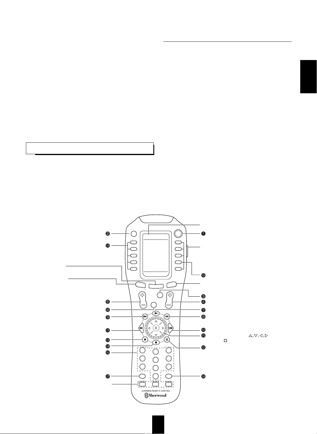
Universal Remote Controls
11
• This section explains the basic functions for Sherwood or OSD mode. For the non-Sherwood mode, refer to the
operating manual of this remote control.
• All Sherwood components bearing the DIGI LINK(II or III) logo can be used with this remote control.
• For system remote control operation, first make the DIGI LINK connections between Sherwood components.
• The numbered buttons on the remote control have different functions in different modes. For details, refer to the
“FUNCTION TABLE of the NUMBERED BUTTONS” on the following page.
• In the DIGI LINK III remote control system, if pressing PLAY, etc. on CD player or tape deck, CD or TAPE
MONITOR is selected automatically on the receiver without selecting the input source. Then PLAY, etc. starts.
Note: For enhanced Universal Remote Programming instructions and manufacturer’s codes, please refer to the operating
manual inclosed with this Universal Remote Control.
This remote control unit has 3 operating modes as follows:
• OSD (On-Screen Display) mode: Allows you to look at information about basic operation of this unit on your monitor TV
and to operate this unit by moving an arrow that appears on the screen of your monitor TV.
• Sherwood mode: Allows you to operate this unit and other Sherwood components like cassette decks, CD players, etc.(To
operate other Sherwood components, you should make the DIGI LINK connections between them.)
• Non-Sherwood mode: Allows you to operate non-Sherwood audio and video components that are remote compatible.
Notes:
• The setup code for each component must be entered before operation.
• For setup codes(manufacturer’s codes), please refer to “Set-Up Code Table” in the operating manual of this remote control.
• Some operation buttons have different functions according to each operation mode.
• Be sure to set the remote control to the correct mode before operation.
DIGI LINK SYSTEM REMOTE CONTROLS
OFF
OSD
POWER
MAIN
PAGE
FAV
MUTE
CH/
SET
VOL
RETURN
DISC
DISP
MI
ROOM 2
1
STEREO
7.1
SURR
CH
2
3
4
5
6
7
8
9
0
ENT
M2
M3
MAIN
AUDIO TV
CD VCR1
DVD VCR2
TAPE SAT
AUX CABLE
AUDIO
AUTO DSP
RNC-500
OSD BUTTON
LCD(FUNCTION) BUTTONS
PAGE BUTTON
While displaying the page menu of the
selected device or the FAVORITE channel menu,
each time this button is pressed, its page changes
VOLUME UP/DOWN(+/-) BUTTONS
NUMERIC(1~0) BUTTONS
• For selecting preset stations in tuner mode.
• For selectiog a track or a disc in CD mode, etc.
• When selecting a disc, select disc No.(1~5)
within 2 sec.after pressing the DISC button.
MACRO BUTTONS
LCD SCREEN
POWER BUTTON
LIGHT BUTTON
Activates the backlighting of the remote control
for a specified time(up to 99 sec.) If any other
button is pressed while the backlighting is on,
the remote control will remain backlit for an
additional period.
FAVORITE BUTTON
Enters the Favorite channel mode.
Each time this button is pressed, its page changes.
LCD(FUNCTION)BUTTONS
MAIN BUTTON
Enters the MAIN menu mode
CHANNEL LEVEL UP/DOWN
(+/-) BUTTONS
CURSOR CONTROL( ),
ENTER( ) BUTTONS
Page 12
ENGLISH
12
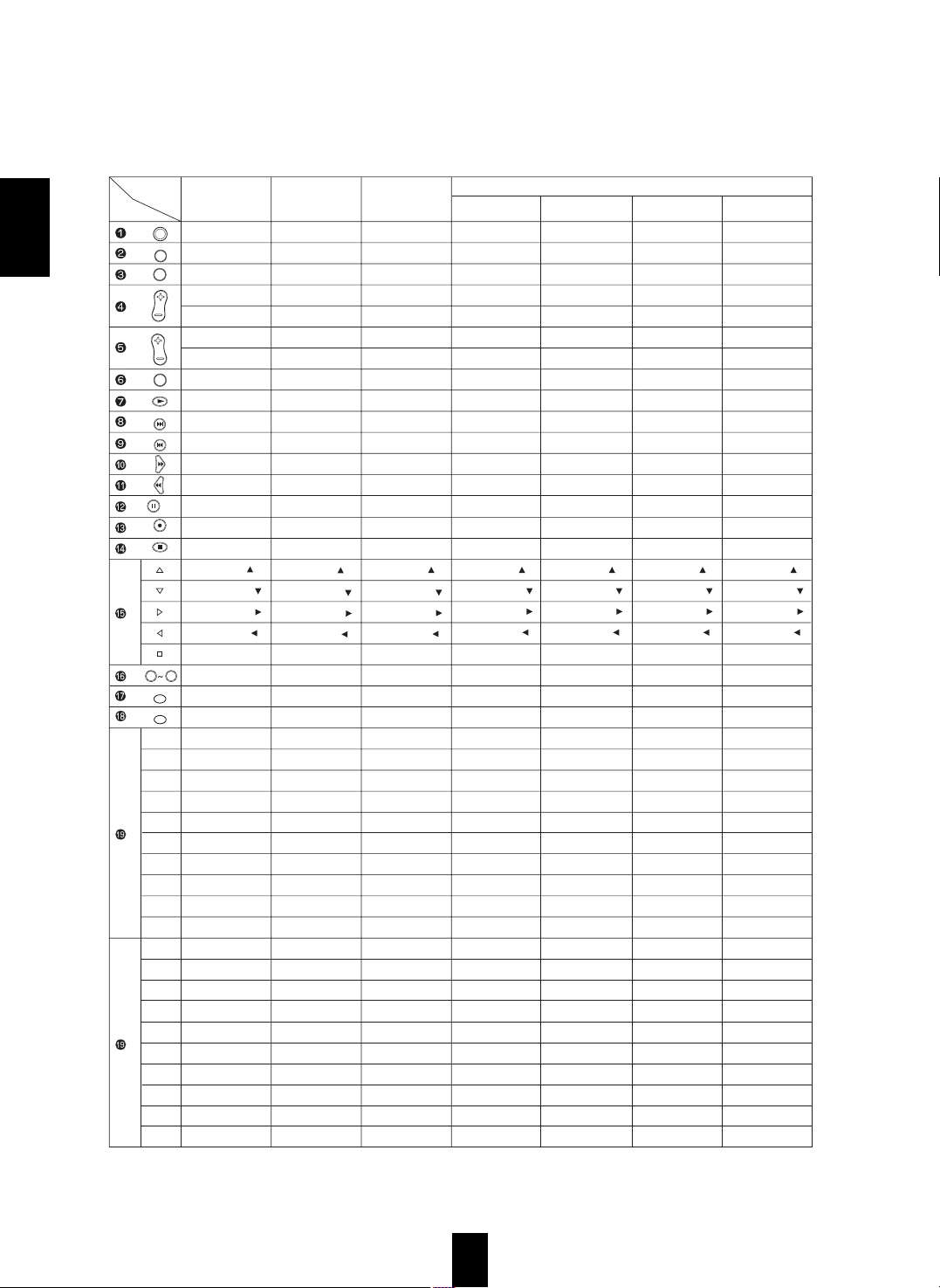
FUNCTION TABLE of the NUMBERED BUTTONS.
Notes:
• Some functions for CD player, tape deck, DVD player, etc. may not be available.
• For details about functions, refer to the operating instructions of each component.
• The functions in < > work for this receiver, not for the CD player or tape deck.
Device to
be controlled
Button
symbol
DVD (for DVD player)
AUDIO
(for receiver, "001")
POWER
ON-SCREEN DISPLAY
CHANNEL SELECTOR
CH LEVEL UP(+)
CH LEVEL DOWN(-)
VOLUME UP(+)
VOLUME DOWN(-)
MUTE
-
DSP MODE
AUTO/MANUAL
-
-
7.1 CH SURROUND
RETURN
STEREO
CURSOR UP( )
CURSOR DOWN( )
CURSOR RIGHT( )
CURSOR LEFT( )
ENTER
0~9
SYSTEM DISPLAY
ROOM2
TUNER
CD
TAPE MONITOR
AUX
PHONO
VIDEO 1
VIDEO 2
VIDEO 3
VIDEO 4
VIDEO 5
AUTO/MANUAL
DTS
DOLBY DIGITAL
PCM
DIGITAL/ANALOG
7.1 CH DIRECT
SOURCE DIRECT
SLEEP
PRESET SCAN
TEST TONE
CD
(for CD player,
"001")
<POWER>
<ON-SCREEN DISPLAY>
<CHANNEL SELECTOR>
<CH LEVEL UP(+)>
<CH LEVEL DOWN(-)>
<VOLUME UP(+) >
<VOLUME DOWN(-)>
< MUTE>
PLAY
<DSP MODE>
<AUTO/MANUAL >
FORWARD SKIP
REVERSE SKIP
PAUSE
-
STOP
<CURSOR UP( )>
<CURSOR DOWN( )>
<CURSOR RIGHT( )>
<CURSOR LEFT( )>
<ENTER>
-
DISC
<ROOM2 >
PLAY
REVERSE SKIP
STOP
REPEAT A< >B
-
PAUSE
FORWARD SKIP
INTRO SCAN
-
-
<DSP MODE>
<PRO LOGIC II MUSIC>
<DTS NEO 6 MUSIC>
<7.1 CH SURROUND >
<STEREO>
<7.1CH DIRECT>
<SOURCE DIRECT >
< SLEEP>
< SYSTEM DISPLAY>
<DIGITAL/ANALOG>
TAPE
(for tape deck,
"001")
<POWER>
<ON-SCREEN DISPLAY>
<CHANNEL SELECTOR>
<CH LEVEL UP(+)>
<CH LEVEL DOWN(-)>
<VOLUME UP(+) >
<VOLUME DOWN(-)>
< MUTE>
FORWARD PLAY
<DSP MODE>
<AUTO/MANUAL >
FAST FORWARD
REWIND
PAUSE
RECORD
STOP
<CURSOR UP( )>
<CURSOR DOWN( )>
<CURSOR RIGHT( )>
<CURSOR LEFT( )>
<ENTER>
-
<SYSTEM DISPLAY>
<ROOM2 >
DECK SELECTOR A
REVERSE PLAY
RECORD
REWIND
STOP
DECK SELECTOR B
FORWARD PLAY
PAUSE
FAST FORWARD
-
<DSP MODE>
<PRO LOGIC II MUSIC>
<DTS NEO 6 MUSIC>
<7.1 CH SURROUND >
<STEREO>
<7.1 CH DIRECT>
<SOURCE DIRECT >
< SLEEP>
< SYSTEM DISPLAY>
-
V-756, etc.
("001")
POWER
MENU
-
-
-
-
-
-
PLAY
FORWARD SKIP
REVERSE SKIP
FORWARD SEARCH
REVERSE SEARCH
PAUSE
RETURN
STOP
CURSOR UP( )
CURSOR DOWN( )
CURSOR RIGHT( )
CURSOR LEFT( )
ENTER
0~9
DISC
-
SETUP
TITLE
AUDIO
SUBTITLE
DISPLAY
OPEN/CLOSE
ZOOM
SEARCH
REPEAT A<>B
REPEAT MODE
MARKER
INTRO SCAN
RANDOM
SUBTITLE ON/OFF
ANGLE
PROGRAM
CLEAR
TIME
SLOW
PAL/NTSC
VD-4103, etc.
("112")
-
MENU
-
-
-
VOLUME UP(+)
VOLUME DOWN(-)
-
STEP
FORWARD SKIP
REVERSE SKIP
FORWARD SEARCH
REVERSE SEARCH
PAUSE
RETURN
STOP
CURSOR UP( )
CURSOR DOWN( )
CURSOR RIGHT( )
CURSOR LEFT( )
ENTER/PLAY
0/10~9
ON-SCREEN DISPLAY
-
SETUP
TITLE
-
SUBTITLE
-
OPEN/CLOSE
-
-
REPEAT A<>B
REPEAT MODE
CHANNEL
INTRO SCAN
-
V-MODE
ANGLE
PROGRAM
MEMORY
A-TIME
SLOW
PAL/NTSC
VD-2103, etc.
("114")
POWER
MENU
-
-
-
VOLUME UP(+)
VOLUME DOWN(-)
MUTE
STEP
FORWARD SKIP
REVERSE SKIP
FORWARD SEARCH
REVERSE SEARCH
PAUSE
RETURN
STOP
CURSOR UP( )
CURSOR DOWN( )
CURSOR RIGHT( )
CURSOR LEFT( )
ENTER/PLAY
0/10~9
DISPLAY
-
SETUP
TITLE
AUDIO
SUBTITLE
-
OPEN/CLOSE
-
SEARCH
REPEAT A<>B
REPEAT MODE
-
RESUME
L/R/ST
PBC
-
PROGRAM
KEY UP
KEY DOWN
SLOW
PAL/NTSC
VD-4106, etc.
("091")
POWER
MENU
-
-
-
-
-
-
PLAY
FORWARD SKIP
REVERSE SKIP
FORWARD SEARCH
REVERSE SEARCH
PAUSE
RETURN
STOP
CURSOR UP( )
CURSOR DOWN( )
CURSOR RIGHT( )
CURSOR LEFT( )
ENTER/SELECT
0~9
DISPLAY
-
SETUP
TITLE
AUDIO
SUBTITLE
SOUND
OPEN/CLOSE
ZOOM
SEARCH
REPEAT A<>B
REPEAT
MARKER
RESUME
RANDOM
ANGLE
-
PROGRAM
CLEAR
REVERSE SLOW
FORWARD SLOW
-
POWER
MUTE
CH/
SET
VOL
CH
DISC
DISP
ROOM 2
ENT
7.1
SURR
STEREO
DSP
AUTO
9
0
(Left 1)
(Left 2)
(Left 3)
(Left 4)
(Left 5)
(Right 1)
(Right 2)
(Right 3)
(Right 4)
(Right 5)
(Left 1)
(Left 2)
(Left 3)
(Left 4)
(Left 5)
(Right 1)
(Right 2)
(Right 3)
(Right 4)
(Right 5)
P
A
G
E
1
P
A
G
E
2
RETURN
OFF
OSD
Page 13
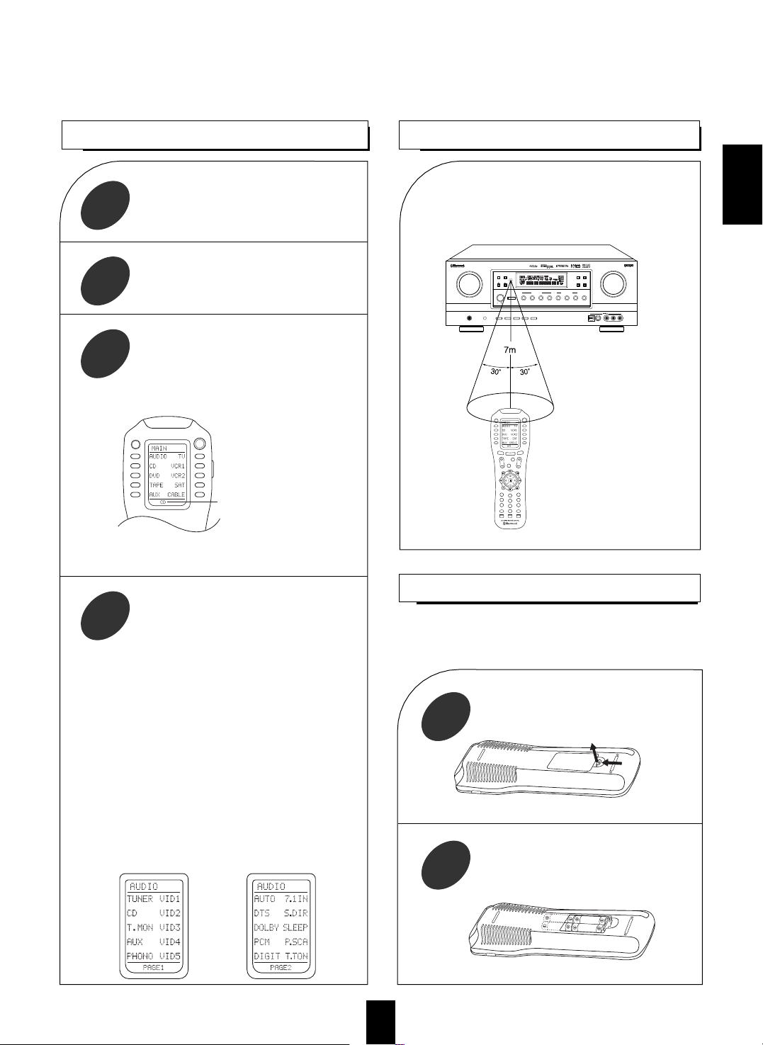
13
LOADING BATTERIES
OPERATING COMPONENTS WITH REMOTE CONTROL
1
2
• When operating a Sherwood CD player or tape deck
using the system remote control, aim the remote
control at the REMOTE SENSOR on this unit.
• However, in case of Sherwood DVD player, aim it
at the REMOTE SENSOR on the corresponding
component.
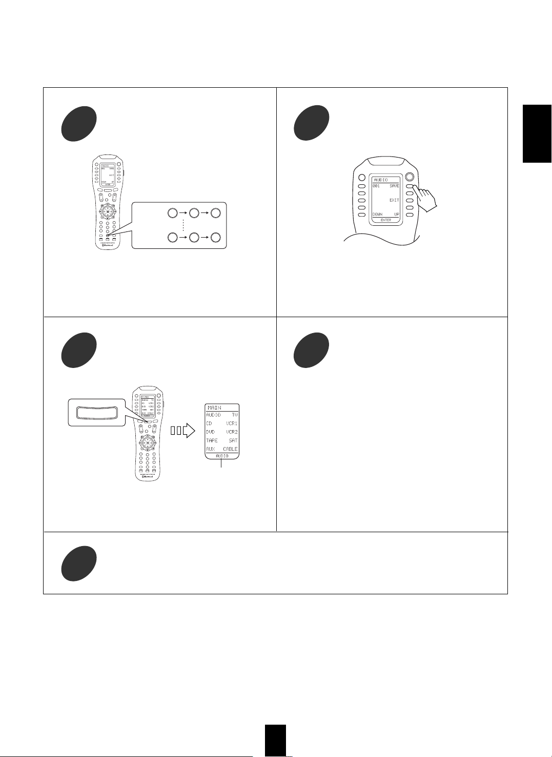
■To select a function on the page menu of the
selected device.
• Find the function by pressing the PAGE button
repeatedly and then press the button corresponding
to the desired function.
Example) when selecting a function on the AUDIO’s
page menu.
POWER
MAIN
P
A
G
E
FAV
MUTE
CH/
SET
VOL
RETURN
DISC
DISP
MI
ROOM 2
1
STEREO
7.1
SURR
CH
2
3
4
5
6
7
8
9
0
ENT
M2
M3
AUTO DSP
RNC-500
CHANNEL
SELECTOR
TONE MODE
A/B
PHONES
SPEAKER
TUNING/PRESET
TEST TONE VIDEO LABEL
ROOM2 FEED
AUDIO/VIDEO SURROUND RECEIVER
R-963
MULTI CONTROL
DYNAMIC
RANGE
T/P MODE
MASTER VOLUME
ON/STANDBY
STANDBY
POWER
BAND CINEMA EQ
MEMO/ENTER
ON /OFF
S-VIDEOOPTICAL IN VIDEO L - AUDIO - R
INPUT SELECTOR
AUDIO VIDEO DIGITAL/ANALOGEXTRA SURR.
6.1/7.1
STEREOTAPE MON. 7.1CH DIRECT DECODING
SURROUND MODE
MULTI ROOM
REMOTE SENSOR
SOURCE
DIRECT
OFF
OSD
REMOTE CONTROL OPERATION RANGE
• Use the remote control within a range of about 7
meters (23 feet) and angles of up to 30 degrees
aiming at the remote sensor.
Remove the cover.
Load four alkaline batteries (“AAA” size.
1.5V) matching the polarity.
When the remote control does not operate or “LOW
BATTERY” is displayed on the LCD screen, etc.,
the old batteries should be replaced.
Enter the setup code of the components
respectively, referring to “ENTERING A
SETUP CODE”(page 14).
Turn on the components you want to
operate.
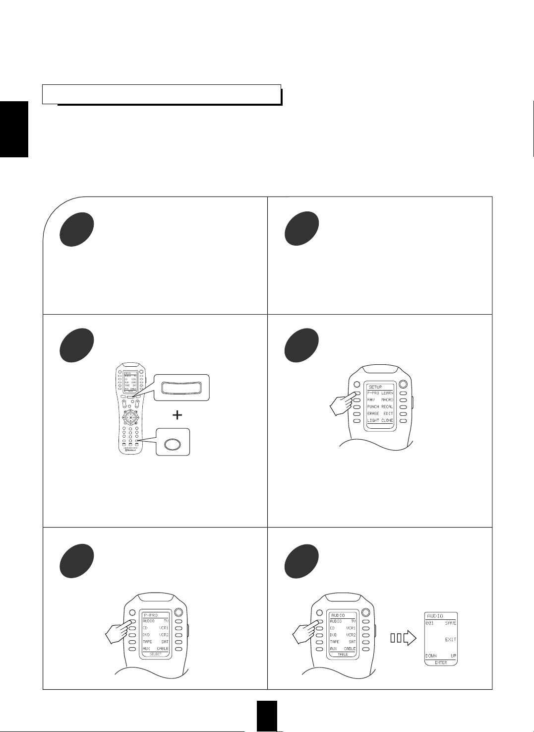
1
Select the device on the main menu of the
remote control corresponding to the
component you want to operate.
2
Press the button corresponding to the
operation you want while aiming the
remote control at the REMOTE SENSOR
on the component.
3
4
Example) When selecting “AUDIO” to operate this
receiver.
• Then the page menu of the selected device will be
displayed.
ENGLISH
POWER
The device selected presently
OFF
OSD
Functions on the page 1 Functions on the page 2
Page 14
14
ENTERING A SETUP CODE
• This remote control can control up to ten different components.
• Before operating audio and video components using the remote control supplied with this receiver, the setup
code for each component should be entered.
• For system remote control operation, the setup code for each Sherwood component such as CD player, tape
deck and DVD player(V-756, etc.) is “001” respectively. (However, the setup code for some Sherwood DVD
player such as VD-4103, etc. is “112”, ”114” or “091”. Enter each setup code for CD player and tape deck doing
from step
③
as follows.
OFF
OSD
POWER
MAIN
PAGE
FAV
MUTE
CH/
SET
VOL
RETURN
DISC
DISP
MI
ROOM 2
1
STEREO
7.1
SURR
CH
2
3
4
5
6
7
8
9
0
ENT
M2
M3
AUTO DSP
RNC-500
ROOM 2
ENT
MAIN
POWER
OFF
OSD
POWER
OFF
OSD
Select the device from which the appropriate
3 digit setup code table will be selected.
Example) If it is the AUDIO code table,
select the AUDIO.
6
Example) The 3 digit setup codes for the Sherwood
“Audio” are 001,024, ...(Hint:The correct
setup code for this receiver is “001”.)
Find the setup code for your component
referring to “Set-Up Code Table” in the
operating manual of this remote control.
2
Turn on the component you want to control.
1
Example) When entering the setup code for this
receiver, turn on this receiver.
■Note:
If you component has the discrete POWER ON and OFF
buttons, please do not turn on the component manually.
POWER
OFF
OSD
Select the Pre-PROgramming mode.
4
Press both the MAIN and ROOM 2(/ENTER)
buttons simultaneously for 3 seconds.
3
Then the Pre-PROgramming menu will be displayed.Then the setup menu will be displayed on the LCD
screen.
■Note:
If the display of the corresponding mode disappears,
start again from the above step ③ or the current mode.
5
Select the device corresponding to the
component you want to control.
Example) When selecting the AUDIO for
receiver or amplifier, etc.
ENGLISH
Page 15
15
The code is saved and the Pre-PROgramming mode
is resumed.
When you do not want to save the code, select the
EXIT on the LCD screen or press the MAIN button.
Confirm that it is the right code by pressing
the POWER button and then save the code.
8
Enter the 3 digit setup code aiming the
remote control at the REMOTE SENSOR on
the component.
7
Your component will be turned off when the right
code is entered.
Continue to enter the corresponding codes until your
component turns off.
Operate the component using the
corresponding function buttons.
10
To resume the MAIN menu mode, press the
MAIN button twice briefly.
9
Each time the MAIN button is pressed, the previous
mode is resumed.
If any of the buttons fails to operate as they should,
start from the step ① again to enter the next setup code.
■Notes:
If the Manufacturer/Brand for your component is not
listed in “Set-Up Code Table” in the operating manual
of this remote control, please use the “ 2 Auto Scan
Method” on page 13 in the operating manual of this
remote control.
Although each setup code is designed to work with
many different modes, certain codes may not work with
some models.( Also, certain codes may only operate
some of the functions available on a given model.)
Repeat the above steps ① to ⑩ for each of your other components.
11
ENGLISH
OFF
OSD
POWER
MAIN
PA
GE
FAV
MUTE
CH/
SET
VOL
RETURN
DISC
DISP
MI
ROOM 2
1
STEREO
7.1
SURR
CH
2
3
4
5
6
7
8
9
0
ENT
M2
M3
AUTO DSP
RNC-500
For "001" :
For "102" :
001
102
OFF
OSD
POWER
MAIN
PAG
E
FAV
MUTE
CH/
SET
VOL
RETURN
DISC
DISP
MI
ROOM 2
1
STEREO
7.1
SURR
CH
2
3
4
5
6
7
8
9
0
ENT
M2
M3
AUTO DSP
RNC-500
MAIN
The selected device
POWER
OFF
OSD
Page 16
16
ADDITIONAL INFORMATION ON REMOTE COMMAND CODES
• This receiver recognizes and responds to IR codes that are not transmitted by the supplied remote control unit.
These commands and their corresponding functions, shown on the following table, are made available for
custom installers and advanced hobbysts who are already familiar with the programming of such devices as the
Crestron Touch Screen and the Philips Pronto.
Custom Code : 8345H(NEC) Custom Code : 8345BH(NEC)
• These are codes for ROOM 2 source playback only.
ENGLISH
FUNCTIONS
MAIN
FUNCTIONS
MAIN
CODES CODES
DTS 70H VIDEO 1 56H
Dolby Digital 71H VIDEO 2 5AH
EXTRA SURROUND
44H VIDEO 3 07H
6.1/7.1
DECODING MODE 58H VIDEO 4 5BH
STEREO 4FH VIDEO 5 5DH
DIGITAL/ANALOG E1H PHONO 02H
Dolby Pro Logic
E8H TUNER 03H
II Movie
Dolby Pro Logic
E9H TAPE MONITOR 06H
II Music
DTS Neo Movie EDH AUX 0AH
DTS Neo Music EEH CD 0BH
MPEG EBH 7.1 CH DIRECT 4AH
PCM EFH SOURCE DIRECT 7BH
DSP MODE 5CH
FUNCTIONS
ROOM 2
FUNCTIONS
ROOM 2
CODES CODES
ROOM 2 91H AUX 8FH
MUTE C3H CD 8BH
VOLUME UP C7H VIDEO 1 8AH
VOLUME DOWN CBH VIDEO 2 8CH
PHONO 82H VIDEO 3 90H
TUNER 83H VIDEO 4 C2H
TAPE MONITOR 86H VIDEO 5 C1H
Page 17
17
ROOM 2 Remote Controls
This remote control unit is an additional remote control unit for the ROOM 2 source playback only.
• Operation of ROOM 2 functions may be easier and more convenient with this remote control instead of using the universal
remote control.
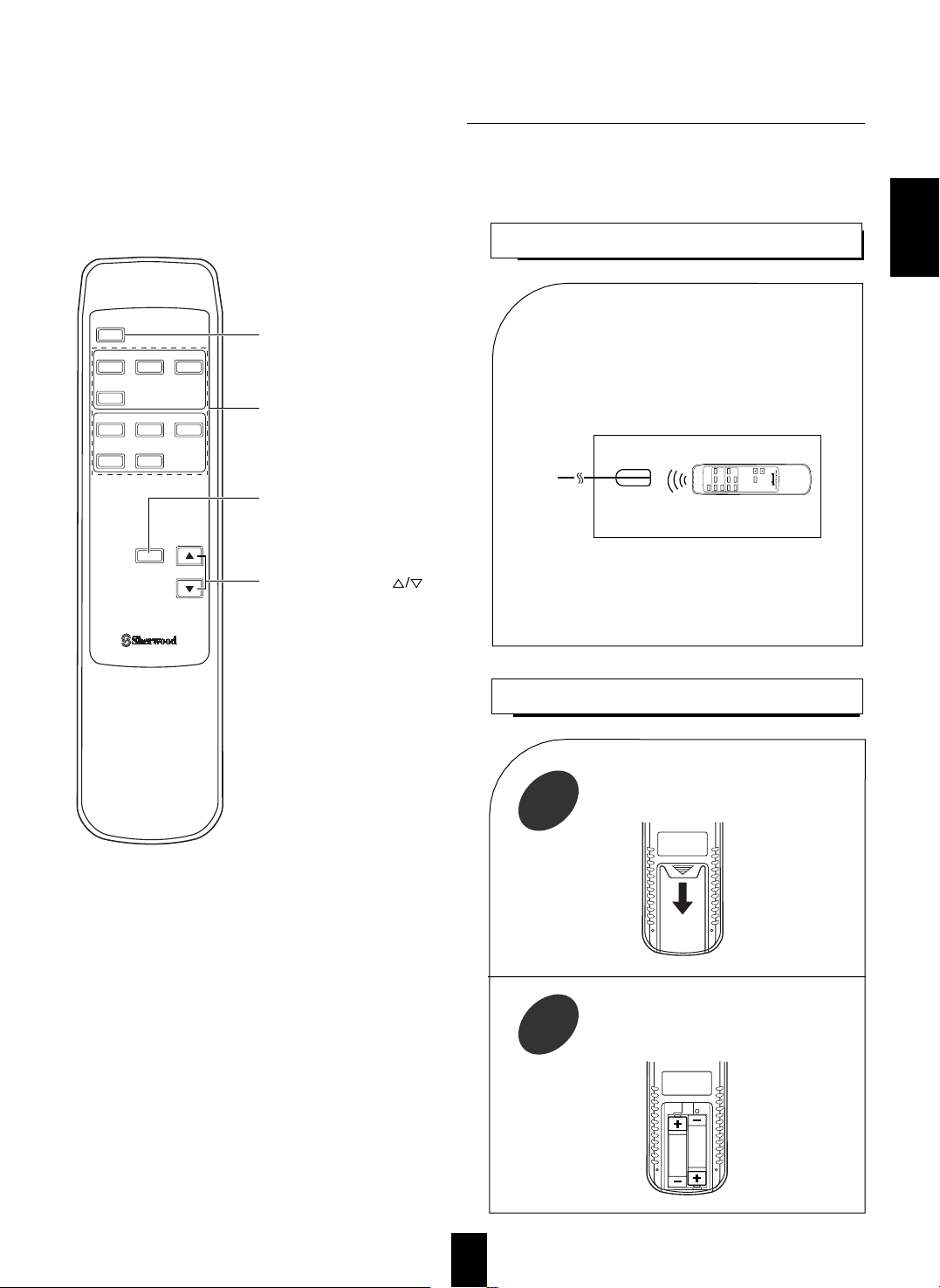
LOADING BATTERIES
1
2
REMOTE CONTROL OPERATION RANGE
• Aim the ROOM 2 remote control(or the
universal remote control) at the IR receiver
installed in another room.(For details, refer to
“CONNECTING MULTI-ROOM SYSTEM
KIT” on page 8.)
• When you operate the ROOM 2 function in the
main room, aim the universal remote control(or
the ROOM 2 remote control) at the remote
sensor of this receiver.
Remove the cover.
Load two batteries (“AAA” size, 1.5V )
matching the polarity.
ENGLISH
ROOM2
PHONO CD
AUX
AUDIO
TUNER
VIDEO 1 VIDEO 2
VIDEO 4 VIDEO 5
MUTE
VOLUME
VIDEO
VIDEO 3
REMOTE CONTROL UNIT RM-103
ROOM 2 BUTTON
Each time this button is pressed,
the ROOM 2 function is activated or
canceled.
ROOM 2 INPUT SELECTOR
BUTTONS
When one of these buttons is pressed,
the corresponding input source is
selected.
VOLUME UP/DOWN( )
BUTTONS
Adjust the sound volume of the
ROOM 2 source.
MUTE BUTTON
Mutes the sound of the ROOM2
source.
•
To resume the previous sound level,
press it again.
Another room
IR receiver
(Multi-room system kit)
To main room
ROOM2
PHONO CD
AUX
AUDIO
TUNER
VIDEO 1 VIDEO 2
VIDEO 4 VIDEO 5
MUTE
VOLUME
VIDEO
VIDEO 3
Page 18

ENGLISH
18
LISTENING TO A PROGRAM SOURCE
Operations
Before operation
Select the desired input source.
3
• Enter the standby mode.
• The STANDBY button lights up in red.
This means that the receiver is not
disconnected from the AC mains and a
small amount of current is retained to
support the memorized contents and
operation readiness.
• To switch the power off, push the POWER switch again.
• Then power is cut off and the STANDBY button goes
off.
• Each time the STANDBY button on the front panel or
the POWER button on the remote control is pressed,
the receiver is turned on to enter the operating mode(the
STANDBY button lights up in blue) or off to enter the
standby mode (the STANDBY button lights up in red).
• In the standby mode, if one of the INPUT SELECTOR
buttons is pressed, the receiver is turned on
automatically and the desired input is selected.
• Each time this button is pressed, the speaker mode
changes as follows and the sound can be heard from the
speakers connected to the selected front speaker
terminals:
Front A( ) Front B( )
Off Front A and B( )
• When using the headphones for private listening , select
the Off mode to switch off the front speakers and all the
others.
In the standby mode, turn the power on.
1
Switch the desired front
speakers on.
2
POWER
ON / OFF
POWER
or
INPUT SELECTOR
AUDIO VIDEO
TAPE MON.
OFF
OSD
OFF
OSD
POWER
MAIN
PAGE
FA
V
MUTE
CH/
SET
VOL
RETURN
DISC
DISP
MI
ROOM 2
1
STEREO
7.1
SURR
CH
2
3
4
5
6
7
8
9
0
ENT
M2
M3
AUTO DSP
RNC-500
ON/STANDBY
STANDBY
or
POWER
A/B
SPEAKER
Notes : Before operating this receiver with the supplied remote control, refer to “ Universal Remote Controls” on page 11 for
details about operation.
Before operating this receiver, first set this unit as desired for optimum performance, by using the OSD menu setting
procedures. (For details, refer to “OSD Menu Settings” on page 35.)
• Each time the “AUDIO” button is pressed, the input
source changes as follows:
PHONO TUNER CD AUX
(frequency display)
• Each time the “VIDEO” button is pressed, the input
source changes as follows:
VIDEO 1 VIDEO 2 ------- VIDEO 5
• When the TAPE MONITOR button is set to on so that
“TAPE MON” lights up, other inputs can not be heard
from the speakers.
To listen to an input source except TAPE MONITOR, be sure
to set the TAPE MONITOR button to off.
TAPE MONITOR function
You can connect either a tape deck or a graphic equalizer to the
receiver’s TAPE MONITOR jacks.
Only when you listen to the component connected to these
jacks, set the TAPE MONITOR button to on.
If you connect a 3-head tape deck, you can listen to the sound
being recorded during recording, and not the source sound.
For further details, refer to the operating instructions of the
connected component.
When selecting the 7.1 CH DIRECT as desired
• Depending on the power amplifier setting for the surround
back channels and the surround back speaker setting, “7.1(,6.1
or 5.1) CH DIRECT” is displayed and the 8(/7/6) separate
analog signals from the component connected to this input
pass through the tone, volume and bass management(if
selected) circuits only and can be heard from your speakers.(In
case that the TAPE MONITOR button is set to on, the TAPE
MONITOR button is automatically set to off.)
• Press the 7.1 CH DIRECT button or select the desired input
source to cancel the 7.1 CH direct function.
• These analog signals can be heard only. They cannot be
recorded.
POWER
or
7.1CH DIRECT
OFF
OSD
Page 19

ENGLISH
19
Operate the selected component for
playback.
5
Select the tone mode as desired.
7
Select the digital or the analog input as
desired.
4
■At the tone defeat mode, each time the MULTI
CONTROL knob is rotated, the tone defeat mode
changes as follows:
DEFEAT ON : When listening to a program source
↕
without the tone effect.
DEFEAT OFF : When adjusting the tone for your
taste.
■At the desired tone (bass or treble), each time the
MULTI CONTROL knob is rotated, the tone level
can be adjusted within the range of +10~ -10 dB.
In general, we recommend the bass and treble to be
adjusted to 0(flat) level.
To complete tone adjustment, repeat the above steps
⑦ and ⑧.
Extreme settings at high volume may damage your
speakers.
When playing back the program sources with
surround sound, refer to “ENJOYING SURROUND
SOUND” on page 24.
Adjust the (overall) volume.
6
At the desired tone mode, adjust as
desired.
8
When CD, TAPE MON or VIDEO 1~
VIDEO 5 is selected
Adjusting the tone (bass and treble)
Each time this button is pressed, the corresponding
input is selected as follows:
DIGITAL ANALOG
To listen to DTS, Dolby Digital or MPEG program
sources in the 2-CH downmix mode, in the stereo
mode, the digital input must be selected. (For details,
refer to “Downmixing into 2 front channels” on page
27.)
When PHONO, TUNER or AUX is selected as an
input source, the analog input is automatically selected.
■Notes:
When the selected digital input is not connected.
“DIGITAL” flickers, meaning no sound. (Refer to
“ENJOYING SURROUND SOUND” on page 24.)
To select the digital input, you must match the
connected DIGITAL IN to the corresponding input
source. (For details, refer to “When selecting the
DIGITAL IN SETUP” on page 41.)
TONE MODE
MULTI CONTROL
OFF
OSD
POWER
MAIN
P
A
G
E
FAV
MUTE
CH/
SET
VOL
RETURN
DISC
DISP
MI
ROOM 2
1
STEREO
7.1
SURR
CH
2
3
4
5
6
7
8
9
0
ENT
M2
M3
AUTO DSP
RNC-500
MASTER VOLUME
DOWN
UP
or
VOL
POWER
or
DIGITAL/ANALOG
OFF
OSD
Each time this button is pressed, the tone mode
changes as follows:
BASS TREBLE DEFEAT OFF(or ON)
The tone display is shown for 5 seconds.
If the tone display disappears, press the TONE
MODE button again.
( ) : When the tone defeat function is activated
(“DEFEAT ON”), bass and treble modes cannot be
selected
■Note:
When the source direct function is activated, the
tone mode cannot be selected.
Page 20

ENGLISH
20
To mute the sound.
11
When 96 kHz PCM(2 channel stereo) signals are
input or the source direct function is selected, the
cinema EQ function can not be selected.
“CINEMA-EQ ON” will scroll on the display.
Press it again to cancel, then “CINEMA-EQ OFF”
will scroll on the display.
“MUTE” lights up.
To resume the previous sound level, press the
button again.
To compensate for edgy or shrill movie
sound tracks.
10
To listen with the headphones.
12
Ensure that the SPEAKER A/B button is set to the
off mode.
When listening to DTS, Dolby Digital or MPEG
program sources, if the headphones are plugged in
and the SPEAKER A/B button is set to the off
mode, the 2-CH downmix mode will be selected
automatically.(For details, refer to “Downmixing
into 2 front channels” on page 27.)
PHONES
To achieve the pure sound quality.
9
Only when playing program sources recorded in
analog stereo or digital 2 ch PCM format, the source
direct function can be selected.
“DIRECT” lights up and stereo mode is
automatically selected. Then the sound that bypasses
the tone circuitry will be heard.
Press the button again to cancel the source direct
function.
When you select the 7.1 CH DIRECT as input
source or the digital signals from DTS, Dolby Digital
or MPEG sources, etc. are input, the source direct
function is automatically canceled.
SOURCE
DIRECT
POWER
OFF
OSD
or
CINEMA EQ
OFF
OSD
POWER
MAIN
PAGE
FAV
MUTE
CH/
SET
VOL
RETURN
DISC
DISP
MI
ROOM 2
1
STEREO
7.1
SURR
CH
2
3
4
5
6
7
8
9
0
ENT
M2
M3
AUTO DSP
RNC-500
MUTE
Page 21

ENGLISH
■■
DTS Digital Surround
DTS Digital Surround(also called simply DTS) is a multi-channel digital signal
format which can handle higher data rates than Dolby Digital. Although both
Dolby Digital and DTS are 5.1 channel formats, discs bearing the “ ”
are generally thought to provide better sound quality due to
the lower audio compression required.
It also provides wide dynamic range and separation, resulting in magnificent
sound.
■■
DTS - ES Extended Surround™
()
This is a new multi channel digital signal format which greatly improves the 360degree surround impression and space expression thanks to further expanded
surround signals, offering high compatibility with the conventional DTS format.
In addition to the 5.1 channels, DTS-ES Extended Surround also offers the
surround back (sometimes also referred to as “surround center”) channel for
surround playback with a total of 6.1 channels. DTS-ES Extended Surround
includes two signal formats with different surround signal recording methods as
follows:
DTS-ES™ Discrete 6.1
Because the signals for 6.1 channels (including the surround back channel) are
fully independent, it is possible to achieve a sense that the acoustic image are
moving about freely among the background sounds surrounding the listener from
360 degrees.
Though maximum performance is achieved when sound tracks recorded with this
system are played using a DTS -ES decoder, when played with a conventional
DTS decoder, the surround back channel signals are automatically downmixed to
the surround left and surround right channels so that none of the signal
components are lost.
DTS - ES™ Matrix 6.1
With this format, the additional surround back channel signals undergo matrix
encoding and are input to the surround left and surround right channels
beforehand. During playback, they are decoded to the surround left, surround
right and surround back channels. Because the bit stream format is 100%
compatible with conventional DTS signals, the effect of the DTS-ES Matrix 6.1
format can be achieved even with DTS 5.1- channel signal sources. Of course, it
is possible to play DTS-ES Matrix 6.1 - channel signal sources with a DTS 5.1 channel decoder.
When DTS-ES Discrete 6.1 or Matrix 6.1 sources are decoded with a DTS - ES
decoder, the format is automatically detected upon decoding and the optimum
surround mode is selected.
However, some DTS - ES Matrix 6.1 sources may be detected as DTS sources. In
this case, the DTS - ES Matrix mode must be selected manually to play these
sources.
In DTS-ES Discrete 6.1 or DTS -ES Matrix 6.1 sources, the surround
back channel is monaural, but can be played through a single(in 6.1
mode) or two surround back speakers(in 7.1 mode) depending on the
surround back speaker setting. (For details, refer to “SETTING THE
SPEAKER SETUP” on page 38.)
DTS Neo : 6™ surround
This mode applies conventional 2-channel signals such as digital PCM or analog
stereo signals to the high precision digital matrix decoder used for DTS-ES
Matrix 6.1 to achieve 6.1-channel surround playback. DTS Neo : 6 surround
includes two modes for selecting the optimum decoding for the signal source.
DTS Neo : 6 Movie
This mode is optimum for playing movies. Decoding is performed with emphasis
on separation performance to achieve the same atmosphere with 2-channel
sources as with 6.1-channel sources.
DTS Neo : 6 Music
This mode is suited mainly for playing music. The front left and front right
signals bypass the decoder and are played directly so there is no loss of sound
quality, and the effect of the surround signals from the center, surround left,
surround right and surround back channels adds a natural sense of expansion to
the sound field.
“DTS”, “DTS-ES Extended Surround” and “Neo : 6” are trademarks of Digital
Theater Systems,Inc.
■■
Dolby Digital
Dolby Digital is the multi- channel digital signal format developed by
Dolby Laboratories. Discs bearing the “ ” includes the
recording of up to 5.1 channels of digital signals, which can reproduce
much better sound quality, spatial expansion and dynamic range
characteristics than the previous Dolby Surround effect.
■■
Dolby Pro Logic
Dolby Pro Logic is a specially encoded two channel surround format
which consists of four channels ( front left, center, front right and
surround). Sources bearing the “ ” provide the
theater - like surround sound.
The surround channel is monaural, but is played through both surround
speakers.
■■
Dolby Pro Logic II surround
This mode applies conventional 2- channel signals such as digital PCM or
analog stereo signals as well as Dolby Surround signals, etc. to surround
processing to offer improvements over conventional Dolby Pro Logic
circuits. Dolby Pro Logic II surround includes two modes as follows:
Dolby Pro Logic II MOVIE
When enjoying movies, this mode allows you to further enhance the
cinematic quality by adding processing that emphasizes the sounds of the
action special effects.
Dolby Pro Logic II MUSIC
When listening to music, this mode allows you to further enhance the sound
quality by adding processing that emphasizes the musical effects.
■■
Dolby Virtual
This mode employs sophisticated digital processing to create the illusion of
“phantom” speakers, this mode allows you to experience surround sound
effects from Dolby Digital, Dolby Surround or 2-channel (recorded in digital
PCM or analog stereo) sources, through just a single pair of front speakers.
Manufactured under license from Dolby Laboratories.
“Dolby”, “Pro Logic”, and the double-D symbol are trademarks of Dolby
Laboratories.
■■
MPEG Multichannel
This mode is a surround system which faithfully reproduces the ambience and
dynamics of movie soundtracks and music alike. Though the number of audio
channels are same as Dolby Digital, discs bearing the “ ”
provides much better at locating individual sounds to the correct and stable
position in the sound stage.
■■
Extra Surround 6.1/7.1
This mode extracts the surround back (sometimes also referred to as “surround
center”) signals from the surround left and surround right signals and
reproduce it as well as the original multichannel signals during playback of
multi-channel program sources recorded in DTS, Dolby Digital, etc.
Surround modes
DOLBY
D I G I T A L
DOLBY SURROUND
21
SURROUND SOUND
This unit incorporates a sophisticated Digital Signal Processor that allows you to create optimum sound quality and sound
atmosphere in your personal Home Theater.
Page 22

ENGLISH
22
The following modes apply conventional 2-channel signals such as digital PCM or analog stereo signals to high
performance Digital Signal Processor to recreate sound fields artificially. Select one of the twelve provided
surround modes according to the program source you want to play.
When using the 7.1 CH DIRECT INPUTs to play back the sound from an the additional multichannel decoder
for surround sound, yon can enjoy the corresponding surround sound ,too.( For details, refer to the operating
instructions of the component to be connected.)
For your reference, the sound from each channel can be reproduced according to the surround modes as follows:
◎ : Depending on the surround back speaker setting, the sound from the SURROUND BACK CENTER or L/R channels can be reproduced.
Depending on the speaker settings and the number of the encoded channels, the sound from the corresponding
channels cannot be reproduced.(For details, refer to “SETTING THE SPEAKER SETUP” on page 38.)
■■
Theater
This mode provides the effect of being in a theater -in-the
round when watching a play.
■■
Movie
This mode provides the effect of being in a movie theater
when watching a movie.
■■
Hall 1/2
This mode provides the ambience of a chamber hall for
chamber music or an instrumental solo (Hall 1) or a
concert hall for orchestral music or an opera (Hall 2).
■■
Stadium
This mode provides the expansive sound field to achieve
the true stadium effect when watching baseball or soccer
games.
■■
Church
This mode provides the ambience of a church for
baroque, string orchestral or choral group music.
■■
Arena 1/2
This mode provides the feeling of a live concert in a
medium - sized (Arena 1) or large (Arena 2) arena.
■■
Club 1/2
This mode creates the sound field of a jazz club with a
low ceiling and hard walls (Club 1) or a live house with a
relatively spacious floor (Club 2).
■■
Game
Use this mode to enjoy video game sources.
■■
Matrix
This mode reproduces a delayed signals from the
surround channels to emphasize the sense of expansion
for music sources.
Channels
FRONT L/R
(FRONT) SURROUND SURROUND BACK
SUBWOOFER
Modes CENTER L/R CENTER, L/R
DTS
—
DTS ES DISCRETE/MATRIX ◎
DTS NEO MOVIE/MUSIC ◎
DOLBY DIGITAL
—
DOLBY PRO LOGIC
—
DOLBY PRO LOGIC II MOVIE/MUSIC
—
DOLBY VIRTUAL
—— —
MPEG
—
EXTRA SURROUND ◎
MATRIX ◎
Other Surround
—
STEREO
—— —
7.1 CH DIRECT ◎
Page 23

ENGLISH
23
Ideal speaker placement varies depending on the size of your room and
the wall coverings, etc. The typical example of speaker placement and
recommendations are as follows :
■■
Front left and right speakers and center speaker
Place the front speakers with their front surfaces as flush with TV or
monitor screen as possible.
Place the center speaker between the front left and right speakers
and no further from the listening position than the front speakers.
Place each speaker so that sound is aimed at the location of the
listener’s ears when at the main listening position.
■■
Surround left and right speakers
Place the surround speakers approximately 1 meter (40 inches) above
the ear level of a seated listener on the direct left and right of them or
slightly behind.
■■
Surround back left and right speakers.
Place the surround back speakers at the back facing the front at a
narrower distance than the front speakers.
When using a single surround back speaker, place it at the rear center
facing the front at a slightly higher position (0 to 10 inches) than the
surround speakers.
We recommend installing the surround back speaker(s) at a slightly
downward facing angle. This effectively prevents the surround back
channel signals from reflecting off the TV or screen at the front center,
resulting in interference and making the sense of movement from the
front to the back less sharp.
■■
Subwoofer
The subwoofer reproduces powerful deep bass sounds.
Place a powered subwoofer anywhere in the front as desired.
■■
Notes :
When using a conventional TV , to avoid interference with the TV
picture, use only magnetically shielded front left and right and center
speakers.
To obtain the best surround effects, the speakers except the subwoofer
should be full range speakers.
Speaker placement
1
11
8
324
5
6
9
7
1. TV or screen
2. Front left speaker
3. Subwoofer
4. Center speaker
5. Front right speaker
6. Surround left speaker
7. Surround right speaker
8. Surround back left speaker
9. Surround back right speaker
10. Surround back center speaker
11. Listeing position
10
Surround speaker
Front speaker
Surround back
speaker
Point slightly
downward
60 to 90 cm
Page 24

ENGLISH
24
ENJOYING SURROUND SOUND
Surround sound effect will not work properly if the signal passes through a graphic equalizer.
Please refer to your equalizer operating instructions for guidance on switching off (or defeating) the equalizer.
Note:
Before surround playback, first perform the SPEAKER SETUP procedure, etc. on the OSD menu for optimum
performance.(For details, refer to “SETTING THE SPEAKER SETUP” on page 38.)
Depending on the input digital signal format, select the desired decoding mode.
1
You can select the “DTS”, “DOLBY DIGITAL” or “PCM”
mode directly on the remote control.
Each time the DECODING MODE button on the front
panel or the AUTO button on the remote control is pressed,
the decoding mode changes as follows :
* Auto mode(“ AUTO” lights up) : The input digital signal
format (DTS, Dolby Digital, MPEG or PCM ( 2 channel
stereo), etc.) used by the selected digital input source is
detected automatically to perform the necessary decoding
process for optimum surround modes.
* Dolby Digital mode(“DOLBY DIGITAL” lights up) : The
Dolby Digital signal processing is performed only when
Dolby Digital signals are input.
* DTS mode(“ DTS” lights up) : The DTS signal processing
is performed only when DTS signals are input.
* MPEG mode(“MPEG” lights up) : The MPEG signal
processing is performed only when MPEG signals are
input.
* PCM mode(“PCM” lights up) : The PCM signal processing
is performed only when PCM signals are input.
or
or
DECODING
POWER
MAIN
PAGE
FAV
MUTE
CH/
SET
VOL CH
AUTO DSP
AUTO
OFF
OSD
Select the desired surround mode.
2
Each time the MULTI CONTROL knob is rotated or the DSP
MODE button is pressed, the surround mode changes depending on
the input signal format and the selected decoding mode as follows :
* When Dolby Digital signals are input in the auto or Dolby Digital mode, the following modes can be selected.
→ DOLBY DIGITAL (↔ DOLBY PRO LOGIC II MOVIE ↔ DOLBY PRO LOGIC II MUSIC ↔ DOLBY PRO LOGIC) ↔ DOLBY VIRTUAL ←
Only when Dolby Digital 2.0 channel signals are input, the surround modes in ( ) can be selected, too.
* When PCM (2 channel stereo) signals are input in the auto or PCM mode, the following modes can be selected.
→ DOLBY PRO LOGIC II MOVIE ↔ DOLBY PRO LOGIC II MUSIC ↔ DOLBY PRO LOGIC ↔ DOLBY VIRTUAL ↔ DTS NEO MOVIE ↔ DTS NEO MUSIC ←
→ MATRIX ↔ GAME ↔ ARENA 2 ↔ ARENA 1 ↔ CLUB 2 ↔ CLUB 1 ↔ CHURCH ↔ STADIUM ↔ HALL 2 ↔ HALL 1↔ MOVIE ↔ THEATER ←
When the analog input is selected as signal input and analog stereo signals are input, you can select the same surround
modes as those listed for the PCM input.
However, when DTS or MPEG signals are input in the following decoding modes, the corresponding surround mode will be
automatically selected regardless of using the MULTI CONTROL knob or DSP MODE button:
* When DTS signals are input in the auto or DTS mode, the corresponding DTS mode will be selected.
* When MPEG signals are input in the auto or MPEG mode, MPEG mode will be selected.
■Notes:
When the selected decoding mode is not matched to the input signal format, the indicator of the signal being input flickers,
meaning the required process cannot be performed and no sound is heard. Therefore, be sure to select the required
decoding mode and the available surround mode according to the input signal format.
When the 7.1 CH DIRECT is selected as an input source, the surround mode cannot be selected.
When the source direct function is activated, the decoding mode and surround mode cannot be selected.
■Notes :
Only when the digital input is selected as signal input for the
input sources except PHONO, TUNER and AUX, the
decoding mode can be selected.
Noise may be generated at the beginning of playback and
while searching during DTS playback in the auto mode. To
minimize this possibility try playing in the DTS mode.
MULTI CONTROL
or
OFF
OSD
POWER
MAIN
PAGE
FA
V
MUTE
CH/
SET
VOL
RETURN
DISC
DISP
MI
ROOM 2
1
STEREO
7.1
SURR
CH
2
3
4
5
6
7
8
9
0
ENT
M2
M3
AUTO DSP
RNC-500
DSP
Page 25

ENGLISH
25
Continued
When playing some multi-channel program sources in the Extra Surround 6.1/7.1 mode.
When the digital signals from the following program sources only are input in the available decoding mode, if
these buttons are pressed, the corresponding surround mode will be selected.
Dolby Digital 5.1-channel sources(including THX Surround EX created using the Dolby Digital Surround EX
technology) : EXTRA SURROUND mode,
DTS 5.1-channel sources : DTS ES MATRIX mode.
Press the EXTRA SURROUND 6.1/7.1 button on the front panel or the 7.1 CH SURROUND button on the
remote control again to cancel the 6.1(or 7.1) surround mode.
According to whether the surround back speaker is set to “1CH” or “2CH”, the 6.1 or 7.1 mode is selected.
However, when the surround back speaker is set to “None”, the Extra Surround 6.1/7.1 mode cannot be activated.
When canceling the surround mode for normal stereo operation.
Then the stereo mode is selected.
To cancel the stereo mode, select the desired surround mode with using the MULTI CONTROL knob or the DSP
MODE button, etc.
OFF
OSD
POWER
MAIN
PAGE
FAV
MUTE
CH/
SET
VOL
RETURN
DISC
DISP
MI
ROOM 2
1
STEREO
7.1
SURR
CH
2
3
4
5
6
7
8
9
0
ENT
M2
M3
AUTO DSP
RNC-500
or
EXTRA SURR.
6.1/7.1
7.1
SURR
OFF
OSD
POWER
MAIN
PAGE
FAV
MUTE
CH/
SET
VOL
RETURN
DISC
DISP
MI
ROOM 2
1
STEREO
7.1
SURR
CH
2
3
4
5
6
7
8
9
0
ENT
M2
M3
AUTO DSP
RNC-500
or
STEREO
STEREO
Page 26

ENGLISH
Adjusting each channel level
Select the desired channel.
3
Adjust the level of the selected channel
as desired.
4
Repeat the above steps ③ and ④ to
adjust each channel level until the sound
level of each speaker is heard to be
equally loud.
5
If you have performed the CH LEVEL TRIM
procedure on the OSD menu, you can skip this
procedure. (For details, refer to “SETTING THE CH
LEVEL TRIM” on page 49.)
Each time this button is pressed, the corresponding
channel is selected and displayed for 3 seconds as
follows:
FRONT-L CENTER(or FRONT-C) FRONT-R SURR-R
SUBWOOFER SURR-L((SURR-C) or ( BACK-L BACK-R))
Depending on the speaker setting, items set to None
or No cannot be selected.
If the channel display disappears, start from the
above step ③ again.
OFF
OSD
POWER
MAIN
PAG
E
FAV
MUTE
CH/
SET
VOL
RETURN
DISC
DISP
MI
ROOM 2
1
STEREO
7.1
SURR
CH
2
3
4
5
6
7
8
9
0
ENT
M2
M3
AUTO DSP
RNC-500
or
MULTI CONTROL
DOWN
UP
CH
OFF
OSD
POWER
MAIN
PAGE
FAV
MUTE
CH/
SET
VOL
RETURN
DISC
DISP
MI
ROOM 2
1
STEREO
7.1
SURR
CH
2
3
4
5
6
7
8
9
0
ENT
M2
M3
AUTO DSP
RNC-500
CH/
SET
or
CHANNEL
SELECTOR
26
Enter the test tone mode.
6
Only when playing a program source in available
surround modes except the DOLBY VIRTUAL
mode, the volume level of each channel can be
adjusted easily with the test tone function.
■Note: When the 7.1 CH DIRECT is selected as an input
source, the test tone function does not work.
At each channel, adjust the level as
desired until the sound level of each
speaker is heard to be equally loud.
7
Cancel the test tone function.
8
Adjusting each channel level with test tone
The test tone will be heard from the speaker of each
channel for 2 seconds as follows:
Front Left Center Front Right Surround Right
Surround Left (( Surround Center) or ( Back Left Back Right))
SUBwoofer
Depending on the speaker setting(None or No), the test
tone of the corresponding channel is not available.
POWER
OFF
OSD
or
TEST TONE
POWER
OFF
OSD
or
TEST TONE
You can select the desired channel and adjust its level
with repeating the steps ③ and ④ in “Adjusting
each channel level” procedure.
OFF
OSD
POWER
MAIN
PAGE
FAV
MUTE
CH/
SET
VOL
RETURN
DISC
DISP
MI
ROOM 2
1
STEREO
7.1
SURR
CH
2
3
4
5
6
7
8
9
0
ENT
M2
M3
AUTO DSP
RNC-500
or
MULTI CONTROL
DOWN
UP
CH
Page 27

27
Downmixing into 2 front channels
To cancel the 2 - CH downmix mode, select the
desired surround mode with using the MULTI
CONTROL knob or the DSP MODE button, etc.
When the playback of the source on the player is
stopped or interrupted, etc, the 2 - CH downmix
mode is not canceled even though “ DTS”,
“DOLBY DIGITAL” or “MPEG” indicator goes
off.
If headphones are plugged in and the SPEAKER
A/B button is set to the off mode while the digital
signals from the DTS, Dolby Digital or MPEG
program sources are being input, it will enter the 2CH downmix mode automatically and if
headphones are unplugged and the SPEAKER A/B
button is set to the speaker-on mode while in the 2CH downmix mode, it will return to the previous
mode.
Allows the multi - channel signals encoded in DTS,
Dolby Digital or MPEG format to be reproduced
through only two front speakers or through
headphones.
When the digital signals from the DTS, Dolby Digital
or MPEG program sources are input, press the
STEREO button.
“DTS”, “MPEG” or “DOLBY DIGITAL” indicator
lights up and “2 CH DOWNMIX” is scrolled,
meaning it enters the 2-CH downmix mode, and then
the discrete multi-channels(except LFE) are mixed
down into 2 front channels.
OFF
OSD
POWER
MAIN
PAGE
FAV
MUTE
CH/
SET
VOL
RETURN
DISC
DISP
MI
ROOM 2
1
STEREO
7.1
SURR
CH
2
3
4
5
6
7
8
9
0
ENT
M2
M3
AUTO DSP
RNC-500
or
STEREO
STEREO
ENGLISH
Page 28

ENGLISH
28
LISTENING TO RADIO BROADCASTS
Auto tuning
Each time this button is pressed, the mode changes
as follows:
Tuning mode : “PRESET” goes off.
Preset mode : “PRESET” lights up.
You can store up to 30 preferred stations in the
memory.
Then “ AUTO” appears on the display. The tuner
will now search until a station of sufficient
strength has been found. The display shows the
tuned frequency and “TUNED”.
If the station found is not the desired one, simply
repeat this operation.
Weak stations are skipped during auto tuning.
“MEMO” is flickering for 5 seconds.
Presetting radio stations
Manual tuning is useful when you already know the frequency of the desired
transmitter.
Perform the steps ①~③ in “Auto tuning” procedure and press the
TUNING/PRESET UP(▲) or DOWN(▼) button repeatedly until the right
frequency has been reached.
Manual tuning
Each time this button is pressed, the band changes
as follows :
FM Stereo mode FM Mono mode AM
(“ STEREO” lights up ) ( “ STEREO” goes off)
When FM stereo broadcasts are poor because of
weak broadcast signals, select the FM mono mode to
reduce the noise, then FM broadcasts are reproduced
in monaural sound.
When pressing the BAND button without selecting
the TUNER, the tuner will be selected automatically.
Select the tuner.
1
Select the tuning mode.
3
Tune in the desired station with auto or
manual tuning.
1
Press the MEMORY/ENTER button.
2
Select the desired band.
2
Press the TUNING/PRESET UP(▲) or
DOWN(▼) button for more than 0.5 second.
4
POWER
or
AUDIO
OFF
OSD
BAND
BAND FREQUENCY
T/P MODE
TUNING/PRESET
TUNING/PRESET
MEMO/ENTER
Page 29

ENGLISH
29
Repeat the above steps ① to ③ to
memorize other stations.
4
After selecting the tuner as input source,
select the preset tuning mode.
1
When using the NUMERIC buttons on the remote
control.
Examples)
For “3” :
For “15” :
For “30” :
The station has now been stored in the memory.
When using the NUMERIC buttons, the station is stored
automatically without pressing the MEMORY/ ENTER
button.
A stored frequency is erased from the memory by storing
another frequency in its place.
If “MEMO” goes off, start again from the above step ②.
Then “PRESET” lights up.
MEMORY BACKUP FUNCTION
The following items, set before the receiver is turned
off, are memorized.
INPUT SELECTOR settings
Surround mode settings
Preset stations, etc.
Note : If the electricity fails or the AC input cord is
disconnected for about 2 weeks, all
memorized settings will be lost.
When using the NUMERIC buttons on the remote
control.
Examples)
For “3”:
For “15”:
For “30”:
When selecting the desired preset number with the
NUMERIC buttons, the desired preset station will be
tuned to automatically without selecting the preset
tuning mode.
Tuning to preset stations
The receiver will start scanning the stations in the
preset sequence and each station is received for 5
seconds.
At the desired station, press this button again to
stop scanning.
Scanning preset stations in sequence
Select the desired preset number.
2
Select the desired preset number(1~30)
and press the MEMORY/ENTER button.
3
TUNING/PRESET
(or )
within 2 seconds
within 2 seconds
3
1 5
0 03
within 2 seconds
3
1 5
0
MEMO/ENTER
TUNING/PRESET
T/P MODE
POWER
OFF
OSD
Page 30

ENGLISH
30
RECORDING
The analog signals from the 7.1 CH DIRECT inputs as well as the digital signals from the coaxial or optical
digital input can be heard but cannot be recorded.
The volume, tone (bass, treble) settings,etc. have no effect on the recording signals.
Start recording on the component hooked
up to TAPE MONITOR.
2
Select the desired input as recording source
except TAPE MONITOR.
1
Start play on the desired input.
3
Be sure that “TAPE MON” goes off.
For tape monitor function, refer to “TAPE MONITOR
function” on page 18.
Start recording on the component hooked
up to VIDEO 1.
2
Select VIDEO 2, VIDEO 3, VIDEO 4 or
VIDEO 5 as a recording source.
1
Start play on the component hooked up
to VIDEO 2, VIDEO 3, VIDEO 4 or
VIDEO 5.
3
or
VIDEO
POWER
OFF
OSD
The audio and video signals from the VIDEO 2,
VIDEO 3, VIDEO 4 or VIDEO 5 component will be
dubbed onto the VIDEO 1 and you can enjoy them on
the TV set and from the speakers.
Dubbing from video components onto
VIDEO 1
Recording with TAPE MONITOR
Select CD as the sound recording source.
2
Select VIDEO 2 as a image recording
source.
Example) When dubbing the VIDEO 2 image signal
and the CD sound signal separately onto
VIDEO 1.
1
or
VIDEO
POWER
OFF
OSD
POWER
or
AUDIO
OFF
OSD
Dubbing the sound and image signals
separately onto VIDEO 1
Image source Sound source
Image source Sound source
POWER
OFF
OSD
or
AUDIO VIDEO
Page 31

ENGLISH
31
DIGITAL AUDIO RECORDING WITH MD RECORDER
For digital recording, select the desired
digital input as the recording signal input.
2
Select a desired input of CD, TAPE
MONITOR and VIDEO 1~VIDEO 5 as a
recording source.
1
Start recording on the component
connected to OPTICAL DIGITAL OUT.
3
Only when the OPTICAL DIGITAL OUT of this receiver is connected to the OPTICAL DIGITAL IN of the MD
recorder or CD recorder, you can enjoy high-quality sound of digital recording without converting the original
signals. Refer to “ CONNECTING AUDIO COMPONENTS” and “CONNECTING DIGITAL INs and OUT” on
page 5 and 7 and the operating instructions of the MD recorder or CD recorder.
Notes:
Digital recording is available for the digital audio program sources such as CDs, MDs, some DVDs, etc.
In most DVDs as well as some CDs, etc., digital recording may not be available depending on the signal
format.
There are some restrictions on recording digital signals. When making digital recordings, refer to the operating
instructions of your digital recording equipment to know what restrictions are imposed.
or
INPUT SELECTOR
AUDIO VIDEO
TAPE MON.
POWER
OFF
OSD
Start play on the desired input.
4
Each time this button is pressed, the corresponding
input is selected as follows:
DIGITAL ANALOG
Note : When the selected digital input is not
connected, “DIGITAL” is flickering. There
will be no recording as well as no sound.
POWER
or
DIGITAL/ANALOG
OFF
OSD
Start recording on the component hooked
up to the VIDEO 1.
3
Start play on the components hooked up to
the VIDEO 2 and the CD respectively.
4
The audio signal from the CD and the video signal
from the VIDEO 2 component will be dubbed and
you can enjoy them on the TV set and from the
speakers.
Note : Be sure to observe the order of the above
steps ① and ②.
Page 32

ENGLISH
32
OTHER FUNCTIONS
This function compresses the dynamic range of
previously specified parts of the Dolby Digital sound
track(with extremely high volume)to minimize the
difference in volume between the specified and nonspecified parts.
This makes it easier to hear all of the sound track
when watching movies at night at low levels.
When the digital signals from the Dolby Digital
program source are input.
Each time this button is pressed, the mode changes
and disappears in 3 seconds as follows:
DYNAMIC : 0.0 : Off
DYNAMIC : 0.5 : Low compression
DYNAMIC : 1.0 : High compression
In some Dolby Digital software, this function may
not be available.
Compressing the dynamic range (Dolby Digital sources only)
The sleep timer allows the system to continue to
operate for a specified period of time before
automatically shutting off.
To set the receiver to automatically turn off after the
specified period of time.
Each time this button is pressed, the sleep time
changes and disappears in 3 seconds as follows:
10 20 30 60 90 OFF
Unit : minutes
While operating the sleep timer, “SLEEP” lights up.
When the sleep time is selected, all display panels of
Sherwood components connected by the DIGI LINK
III are dimly lit.
Each time this button is pressed, the brightness of
all fluorescent displays of Sherwood components
connected by the DIGI LINK III changes together
as follows:
ON dim OFF
In the display OFF mode, pressing any button will
restore the display ON mode.
Operating the sleep timer
Adjusting the brightness of the
fluorescent displays
POWER
OFF
OSD
OFF
OSD
POWER
MAIN
P
AGE
FAV
MUTE
CH/
SET
VOL
RETURN
DISC
DISP
MI
ROOM 2
1
STEREO
7.1
SURR
CH
2
3
4
5
6
7
8
9
0
ENT
M2
M3
AUTO DSP
RNC-500
DISC
DISP
DYNAMIC
RANGE
Page 33

ENGLISH
33
Select the desired video input source to
enter its label.
1
Press the VIDEO LABEL button to enter the
video label mode.
Example) When selecting VIDEO 1.
2
Select the character on the flickering digit.
3
Confirm your selection.
4
Repeat the above steps ③ and ④ to enter
the desired characters on the rest of the
digits.
5
Memorize the desired video label.
6
Entering a video label
Select the desired video input source to be
rectified or cleared.
1
Repeat the steps ②~⑥ in “Entering a
video label” procedure.
2
Correcting or clearing a video label
Each time the MULTI CONTROL knob is rotated,
the characters change as follows:
Blank ( )
Alphabets: A~Z, a~z
Numerals: 0~9
Symbols: ( ) + , . ̄/
This function can be operated only on video input
sources such as VIDEO 1~5.
Then the next digit will flicker.
On up to 9 digits, the desired characters can be entered.
Note: If any button such as “AUDIO”, “VIDEO”, “7.1
CH DIRECT” button, etc. is pressed while
entering a video label, the video label mode will
be canceled.
To clear a video label, make a blank on each digit
and memorize it, then the video label is cleared and
its factory video input source will be displayed.
If the VIDEO LABEL button is pressed for more
than 3 seconds, blanks will be made on all the digits
at once.
or
VIDEO
POWER
OFF
OSD
or
VIDEO
POWER
OFF
OSD
MULTI CONTROL
VIDEO LABEL
VIDEO LABEL
MEMO/ENTER
Page 34

ENGLISH
34
ROOM 2 SOURCE PLAYBACK
This function allows enjoying one source in the main room and playing another in a different room at the same time.
The analog signals from the 7.1 CH DIRECT inputs and TAPE MONITOR INs as well as the digital signals from the coaxial or
optical digital input cannot be output from the ROOM 2 OUTs, meaning no playback in a different room.
When you connect the multi - room adapter to the MULTI - ROOM jack of this unit, you can control this unit with not only the
universal remote control unit but also the ROOM 2 remote control unit in a different room, too.(For details, refer to
“CONNECTING MULTI - ROOM SYSTEM KIT” on page 8 and “ROOM 2 Remote Controls” on page 17.)
■When using the ROOM 2 remote control unit
You can use the ROOM 2 function with the ROOM 2
remote control unit more conveniently.
Press the ROOM 2 button.
1
■When using the universal remote control unit or the
buttons on the front panel.
Press the ROOM 2 button.
1
Select the desired
input as a ROOM 2
source.
2
“R2” is flickering for 3 seconds and the
ROOM 2 function is activated.
To cancel the ROOM 2 function, press it again.
Then “R2” goes off.
In the operating mode, when one of the ROOM 2 INPUT
SELECTOR buttons on this remote control is pressed, the
ROOM 2 function is automatically activated without pressing
the ROOM 2 button and the desired input is selected.
The selected ROOM 2 source is displayed for 3 seconds as
follows: (R2) PHONO, (R2) TUNER, (R2) CD, (R2) AUX,
(R2) VIDEO 1~5.
Only these sources can be played in another room.
When an audio program source is selected as a ROOM 2
source, the image of the video program source selected
previously can be played separately, too.(For details, refer to
“SETTING THE ROOM2 FEED SETUP” on page 50.)
The MUTE and VOLUME UP/DOWN(▲/▼) buttons on this
remote control can be available for the ROOM 2 source only.
Note:
When the muting effect for the ROOM 2 source is operating,
“R2” is flickering.
Start play on the component related to the
ROOM 2 source.
3
Select the desired input as a ROOM 2 source
while “R2” is flickering.
2
“R2” flickers for 3 seconds and the ROOM 2 function is
activated.
To cancel the ROOM 2 function, press the button.
Then “R2” goes off.
You can cancel the ROOM 2 function with using these
buttons even in the standby mode.
The selected ROOM 2 source is displayed for 3 seconds.
Only while “R2” is flickering, the volume level for the
ROOM 2 source can be adjusted.
When “R2” is not flickering and lights up, press the ROOM
2 button briefly twice.
Start play on the component related to the
ROOM 2 source.
3
Notes:
Even when this unit enters the standby mode, in such a case that “R2” lights up still and the STANDBY button lights up in blue
as it does in the operating mode, meaning only the ROOM 2 circuitry operates, the ROOM 2 source can be played independently.
When the ROOM 2 function is operating in the standby mode, only the ROOM 2 remote control unit is available.
When you do not use the ROOM 2 function, cancel the ROOM 2 function to save electricity.
For ROOM 2 volume adjustment, refer to “ SETTING THE ROOM 2 FEED SETUP” on page 50.
ROOM2 FEED
or
OFF
OSD
POWER
MAIN
P
A
G
E
FAV
MUTE
CH/
SET
VOL
RETURN
DISC
DISP
MI
ROOM 2
1
STEREO
7.1
SURR
CH
2
3
4
5
6
7
8
9
0
ENT
M2
M3
AUTO DSP
RNC-500
ROOM 2
ENT
POWER
OFF
OSD
or
AUDIO VIDEO
ROOM2
PHONO CD
AUX
AUDIO
TUNER
VIDEO 1 VIDEO 2
VIDEO 4 VIDEO 5
MUTING
VOLUME
VIDEO
VIDEO 3
ROOM2
ROOM2
PHOTO CD
AUX
AUDIO
TUNER
VIDEO 1 VIDEO 2
VIDEO 4 VIDEO 5
MUTING
VOLUME
VIDEO
VIDEO 3
PHONO CD
AUX
AUDIO
TUNER
VIDEO 1 VIDEO 2
VIDEO 4 VIDEO 5
VIDEO
VIDEO 3
Page 35

ENGLISH
35
Using the OSD
CURRENT STATUS DISPLAY
This mode shows the status corresponding to each operation.
The on-screen display will automatically disappear in 5 seconds.
For examples, there are 2 status displays as follows.
■Note : When watching a movie earnestly, if you want to turn off the current status display function, set the
OSD mode to Off.(For details, refer to “When selecting the OSD MODE” on page 44.)
When selecting the desired input source. When selecting the TEST TONE mode.
This unit incorporates an OSD(On-screen display) function to provide information about basic operation of this unit and to
simplify the setup procedures.
The OSD function uses a monitor TV connected to this unit as a display and has two kinds of display modes such as current
status display and menu screen.
■Notes: The OSD function is not available via the component video connection.
Any on-screen display shown on the monitor TV will not be recorded onto VIDEO 1.
The OSD menu allows you to perform the setup procedures easily. In most situations, you will only need to set this
once during the installation and layout of your home theater, and it rarely needs to be changed later. The OSD
menu consists of 6 main menus: power amp assign, speaker setup, function select, surround setup, CH level trim
and room 2 feed setup. Some of these menus are divided up into various sub-menus.
The OSD menu settings are performed easily with the CURSOR control(▲, ▼, ◀, ▶), ON-SCREEN DISPLAY,
RETURN and ENTER buttons.
The “3”, “7”, “8” and “9” of the NUMERIC buttons do also work as the CURSOR control(▲, ▼, ◀, ▶)buttons do. In
this case, the “3” button stands for the CURSOR UP(▲) button, the “7” for the CURSOR LEFT(◀), the “8” for the
CURSOR DOWN(▼) and the “9” for the CURSOR RIGHT(▶ ).
VIDEO 1 (OPTICAL1)
Input source Signal input
Channel level or overall volume display
FL :
------ ------
: 0 dB
The main menu will be shown.
To turn the menu screen off, press this button again.
In the bottom of the display, “OSD” stands for the ON-
SCREEN DISPLAY button, “RETURN” for “RETURN”,
“ENTER” for “ENTER”, “▲”, “▼”, “◀” and “▶” for
CURSOR UP(▲), DOWN(▼), LEFT(◀) and RIGHT(▶).
OFF
OSD
POWER
MAIN
P
A
G
E
FAV
MUTE
CH/
SET
VOL
RETURN
DISC
DISP
MI
ROOM 2
1
STEREO
7.1
SURR
CH
2
3
4
5
6
7
8
9
0
ENT
M2
M3
AUTO DSP
RNC-500
OFF
OSD
MAIN MENU
OSD:Quit ENTER:Select
POWER AMP ASSIGN
SPEAKER SETUP
FUNCTION SELECT
SURROUND SETUP
CH LEVEL TRIM
ROOM2 FEED SETUP
When adjusting each channel level or overall volume, the volume
level display will be shown.
The test tone display will be shown until the test tone mode is
canceled.
Turn the menu screen on.
1
OSD Menu Settings
Page 36

ENGLISH
36
Select the desired menu using the CURSOR
UP(▲)/DOWN(▼) buttons.
2
OFF
OSD
POWER
MAIN
PA
GE
FAV
MUTE
CH/
SET
VOL
RETURN
DISC
DISP
MI
ROOM 2
1
STEREO
7.1
SURR
CH
2
3
4
5
6
7
8
9
0
ENT
M2
M3
AUTO DSP
RNC-500
■When selecting the POWER AMP ASSIGN. ■When selecting the SPEAKER SETUP.
■When selecting the FUNCTION SELECT. ■When selecting the SURROUND SETUP.
■When selecting the CH LEVEL TRIM. ■When selecting the ROOM2 FEED SETUP.
For the setting details, see page in .
Adjust the setting(s) in each setting category to your preference.
When the RETURN button is pressed on a sub-menu, the previous menu is resumed.
Confirm your selection.
3
SPEAKER SETUP
RETURN:Back ENTER:Select
SPEAKER CONFIG
SPEAKER DISTANCE
LFE LEVEL CONTROL
38
41
FUNCTION SELECT
RETURN:Back ENTER:Select
INPUT SETUP
TONE CONTROL
OSD MODE
DC TRIGGER
LISTEING MODE
47
SURROUND SETUP
RETURN:Back , :Select
SOURCE DIRECT :
DECODING MODE :
DOLBY DIGITAL
CINEMA EQ :
Off
Off
AUTO
37
POWER AMP ASSIGN
RETURN:Back , :Select
S/BACK
ROOM 2
CH LEVEL TRIM
RETURN:Back , :Select
FL :
------ ------
: 0 dB
C:
------ ------
: 0 dB
FR :
------ ------
: 0 dB
SR :
------ ------
: 0 dB
BR :
------ ------
: 0 dB
BL :
------ ------
: 0 dB
SL :
------ ------
: 0 dB
SW :
------ ------
: 0 dB
49
ROOM2 FEED SETUP
RETURN:Back ENTER:Select
VOLUME MODE
FUNCTION SELECT
50
OFF
OSD
POWER
MAIN
PAGE
FAV
MUTE
CH/
SET
VOL
RETURN
DISC
DISP
MI
ROOM 2
1
STEREO
7.1
SURR
CH
2
3
4
5
6
7
8
9
0
ENT
M2
M3
AUTO DSP
RNC-500
The selected category or item will provide the
needed setting details using the subsequent screens.
Page 37

ENGLISH
You can assign the power amplifier for the surround back channels to the ROOM 2.
In this case, you need not use the power amplifier to drive the speakers additionally in a different room
(ROOM 2).
OFF
OSD
POWER
MAIN
PAGE
FAV
MUTE
CH/
SET
VOL
RETURN
DISC
DISP
MI
ROOM 2
1
STEREO
7.1
SURR
CH
2
3
4
5
6
7
8
9
0
ENT
M2
M3
AUTO DSP
RNC-500
POWER AMP ASSIGN
RETURN:Back , :Select
S/BACK
ROOM 2
37
SETTING THE POWER AMP ASSIGN
Each time these buttons are pressed, the power amplifier is
assigned as follows :
S /BACK : Select this to use power amplifier
↕ for the surround back channels.
ROOM 2 : Select this to use it for the ROOM 2.
Press the CURSOR LEFT(◀)/RIGHT(▶) buttons to use the power amplifier as desired.
Page 38

ENGLISH
38
After you have installed this unit and connected all the components, you first perform the speaker setup settings for
the optimum sound acoustics according to your environment and speaker layout.
Depending on your speaker type, you can select one of these following speaker types.
Yes/No : Select the desired depending on whether a subwoofer is connected or not.
Large : Select this when connecting speakers that can fully reproduce sounds below 80 Hz.
Small : Select this when connecting speakers that cannot fully reproduce sounds below 80 Hz.
When this is selected, sounds below 80 Hz are sent to the subwoofer.
None : Select this when no speakers are connected.
When this is selected, sounds are sent to the front speakers.
2CH/1CH : Select the desired depending on the number of surround back speakers.
Each time these buttons are pressed, “◀” and “▶” are
moved to the corresponding speaker mode.
Notes :
When “FRONT’ is set to “Small”, “SUBWOOFER” is automatically set to “Yes”, and when “SUBWOOFER” is set to
“No”, “FRONT” is automatically set to “Large”.
When “FRONT” is set to “Small”, “CENTER”, “SURROUND” and “S/B CH” cannot be set to “Large”.
When “SURROUND” is set to “None”, “SURR. BACK” cannot be selected.
When “CENTER” is set to “None”, “SURROUND” cannot be set to “None” and vice versa.
When “SURROUND” is set to “Small”, “S/B CH” cannot be set to “Large”.
SPEAKER CONFIG
RETURN:Back , :Select
OFF
OSD
SUBWOOFER :
FRONT :
CENTER :
SURROUND :
SURR.BACK :
S/B CH :
Large
Yes
Large
Large
2CH
Small
POWER
MAIN
P
A
G
E
FAV
MUTE
CH/
SET
VOL
RETURN
DISC
DISP
MI
ROOM 2
1
STEREO
7.1
SURR
CH
2
3
4
5
6
7
8
9
0
ENT
M2
M3
AUTO DSP
RNC-500
OFF
OSD
POWER
MAIN
P
A
G
E
FAV
MUTE
CH/
SET
VOL
RETURN
DISC
DISP
MI
ROOM 2
1
STEREO
7.1
SURR
CH
2
3
4
5
6
7
8
9
0
ENT
M2
M3
AUTO DSP
RNC-500
OFF
OSD
POWER
MAIN
P
A
G
E
FAV
MUTE
CH/
SET
VOL
RETURN
DISC
DISP
MI
ROOM 2
1
STEREO
7.1
SURR
CH
2
3
4
5
6
7
8
9
0
ENT
M2
M3
AUTO DSP
RNC-500
SPEAKER SETUP
RETURN:Back ENTER:Select
SPEAKER CONFIG
SPEAKER DISTANCE
LFE LEVEL CONTROL
To select the sizes of the speakers that are connected.
To enter the distance between the listening position and
each speaker to set the delay time automatically for
the optimum surround playback.
To adjust LFE(Low Frequency Effect) levels included in
Dolby Digital, DTS and MPEG program sources.
Press the CURSOR UP(▲)/DOWN(▼) buttons to select the SPEAKER CONFIG, then press the ENTER
button.
1
Press the CURSOR UP(▲)/DOWN(▼) buttons to select the desired speaker.
2
Press the CURSOR LEFT(◀)/RIGHT(▶) buttons to select the desired mode.
3
SETTING THE SPEAKER SETUP
When selecting the SPEAKER CONFIG
Page 39

ENGLISH
39
Repeat the above steps ② and ③ until the speakers are all set to the desired mode.
4
Repeat the above steps ④ and ⑤ until the distances are all entered.
6
Press the CURSOR LEFT(◀)/RIGHT(▶) buttons to enter the distance from the selected speaker to the
listening position.
5
Press the CURSOR UP(▲)/DOWN(▼) buttons to select the SPEAKER DISTANCE, then press the
ENTER button.
1
When selecting the SPEAKER DISTANCE
Press the CURSOR UP(▲)/DOWN(▼) buttons to select the desired speaker.
4
Then “◀” and “▶” are moved to the unit mode.
Each time these buttons are pressed, “Meters” or “Feet” is
selected.
Once a unit is selected, the distances are automatically
changed in the selected unit.
Then “◀” and “▶” are moved to its distance.
You cannot select the subwoofer, surround back speakers and the speakers set to “None”.
You can set the distance within the range of 0.3~9 meters in 0.3 meter intervals(or 1~30 feet in 1 feet intervals)
OFF
OSD
POWER
MAIN
P
A
G
E
FAV
MUTE
CH/
SET
VOL
RETURN
DISC
DISP
MI
ROOM 2
1
STEREO
7.1
SURR
CH
2
3
4
5
6
7
8
9
0
ENT
M2
M3
AUTO DSP
RNC-500
OFF
OSD
POWER
MAIN
P
A
G
E
FAV
MUTE
CH/
SET
VOL
RETURN
DISC
DISP
MI
ROOM 2
1
STEREO
7.1
SURR
CH
2
3
4
5
6
7
8
9
0
ENT
M2
M3
AUTO DSP
RNC-500
Press the CURSOR UP(▲)/DOWN(▼) buttons to select the unit.
2
Press the CURSOR LEFT(◀)/RIGHT(▶) buttons to select the desired unit.
3
SPEAKER DISTANCE
RETURN:Back , :Select
UNIT :
FRONT L : 3.0m
FRONT R : 3.0m
CENTER : 3.0m
SURR. L : 3.0m
SURR. R : 3.0m
Meters
OFF
OSD
POWER
MAIN
P
A
G
E
FAV
MUTE
CH/
SET
VOL
RETURN
DISC
DISP
MI
ROOM 2
1
STEREO
7.1
SURR
CH
2
3
4
5
6
7
8
9
0
ENT
M2
M3
AUTO DSP
RNC-500
Page 40

ENGLISH
40
Repeat the above steps ② and ③ until each level is adjusted as desired.
4
Each time these buttons are pressed, “▶” is moved to the
corresponding LFE level mode.
Each time these buttons are pressed, the LFE level can
be adjusted within the range of either -10~0 dB for
Dolby Digital program sources or -10~+10 dB for DTS
and MPEG program sources.
In general, we recommend the LFE level for Dolby
Digital program sources to be set at 0 dB and +10 dB for
DTS program sources.(However, the recommended LFE
level for some early DTS program sources is 0 dB.)
If the recommended levels seem too high, lower the
setting as necessary.
Press the CURSOR UP(▲)/DOWN(▼) buttons to select the LFE LEVEL CONTROL, then press the
ENTER button.
1
Press the CURSOR UP(▲)/DOWN(▼) buttons to select the desired LFE level mode.
2
Press the CURSOR LEFT(◀)/RIGHT(▶) buttons to adjust the selected LFE level as desired.
3
When selecting the LFE LEVEL CONTROL
OFF
OSD
POWER
MAIN
PAGE
FAV
MUTE
CH/
SET
VOL
RETURN
DISC
DISP
MI
ROOM 2
1
STEREO
7.1
SURR
CH
2
3
4
5
6
7
8
9
0
ENT
M2
M3
AUTO DSP
RNC-500
OFF
OSD
POWER
MAIN
PAGE
FAV
MUTE
CH/
SET
VOL
RETURN
DISC
DISP
MI
ROOM 2
1
STEREO
7.1
SURR
CH
2
3
4
5
6
7
8
9
0
ENT
M2
M3
AUTO DSP
RNC-500
LFE LEVEL CONTROL
RETURN:Back , :Select
DOLBY
-----
+
0 dB
DTS
-----+-----
0 dB
MPEG
-----+-----
0 dB
OFF
OSD
POWER
MAIN
P
A
G
E
FAV
MUTE
CH/
SET
VOL
RETURN
DISC
DISP
MI
ROOM 2
1
STEREO
7.1
SURR
CH
2
3
4
5
6
7
8
9
0
ENT
M2
M3
AUTO DSP
RNC-500
Page 41

ENGLISH
41
Each time these buttons are pressed, “◀” and “▶” are
moved to the corresponding DIGITAL IN.
When selecting the DIGITAL IN SETUP
You can match the connected DIGITAL INs to the desired of CD, TAPE MONITOR and VIDEO 1~5.
(For details, refer to “CONNECTING DIGITAL INs and OUT” on page 7.)
Note:
When the source direct function is selected, the TONE CONTROL cannot be selected.
To match the connected
DIGITAL INs to the desired
input sources respectively.
To select a video input source.
INPUT SETUP
RETURN:Back ENTER:Select
DIGITAL IN SETUP
VIDEO SELECT
OFF
OSD
POWER
MAIN
PAGE
FAV
MUTE
CH/
SET
VOL
RETURN
DISC
DISP
MI
ROOM 2
1
STEREO
7.1
SURR
CH
2
3
4
5
6
7
8
9
0
ENT
M2
M3
AUTO DSP
RNC-500
CD :
TAPE MON :
VIDEO1 :
VIDEO2 :
VIDEO3 :
VIDEO4 :
VIDEO5 :
OPT4
OPT1
OPT2
OPT3
COAX2
OPT5
COAX1
DIGITAL IN SETUP
RETURN:Back , :Select
OFF
OSD
POWER
MAIN
PAGE
FAV
MUTE
CH/
SET
VOL
RETURN
DISC
DISP
MI
ROOM 2
1
STEREO
7.1
SURR
CH
2
3
4
5
6
7
8
9
0
ENT
M2
M3
AUTO DSP
RNC-500
To adjust the input source as desired.
To adjust the tone as desired.
To select the desired OSD mode.
To select the desired input source that uses
the DC trigger function.
To select the desired digital re-mastering mode.
FUNCTION SELECT
RETURN:Back ENTER:Select
INPUT SETUP
TONE CONTROL
OSD MODE
DC TRIGGER
LISTENING MODE
Press the CURSOR UP(▲)/DOWN(▼) buttons to select the INPUT SETUP, then press the ENTER button.
1
Press the CURSOR UP(▲)/DOWN(▼) buttons to select the DIGITAL IN SETUP, then press the ENTER
button.
2
Press the CURSOR UP(▲)/DOWN(▼) buttons to select the desired input source.
3
SETTING THE FUNCTION SELECT
When selecting the INPUT SETUP
OFF
OSD
POWER
MAIN
PAGE
FAV
MUTE
CH/
SET
VOL
RETURN
DISC
DISP
MI
ROOM 2
1
STEREO
7.1
SURR
CH
2
3
4
5
6
7
8
9
0
ENT
M2
M3
AUTO DSP
RNC-500
“OPT 5” means the OPTICAL IN on the front panel.
Page 42

ENGLISH
42
Press the CURSOR LEFT(◀)/RIGHT(▶) buttons to select the desired DIGITAL IN.
4
Each time these buttons are pressed, the DIGITAL INs change.
Notes:
When you select “None” instead of a DIGITAL IN for an input
source, the analog input is automatically selected.
In such a case that a DIGITAL IN is matched to two input
sources or more, when these input sources are selected, the digital
audio signals can be heard from the same DIGITAL IN.
Each time these buttons are pressed, the video input
source changes.
When you select the VID 6, you can enjoy the image of
the 7.1 CH DIRECT source.
VIDEO IN :
VID 1
VIDEO SELECT
RETURN:Back , :Select
OFF
OSD
POWER
MAIN
PAGE
FAV
MUTE
CH/
SET
VOL
RETURN
DISC
DISP
MI
ROOM 2
1
STEREO
7.1
SURR
CH
2
3
4
5
6
7
8
9
0
ENT
M2
M3
AUTO DSP
RNC-500
OFF
OSD
POWER
MAIN
PAGE
FAV
MUTE
CH/
SET
VOL
RETURN
DISC
DISP
MI
ROOM 2
1
STEREO
7.1
SURR
CH
2
3
4
5
6
7
8
9
0
ENT
M2
M3
AUTO DSP
RNC-500
Repeat the above steps ③ and ④ until the connected DIGITAL INs are matched to the desired input
sources respectively.
5
Press the CURSOR UP(▲)/DOWN(▼) buttons to select the VIDEO SELECT, then press the ENTER
button.
2
Press the CURSOR LEFT(◀)/RIGHT(▶) buttons to select the desired video input source.
3
OFF
OSD
POWER
MAIN
PAGE
FAV
MUTE
CH/
SET
VOL
RETURN
DISC
DISP
MI
ROOM 2
1
STEREO
7.1
SURR
CH
2
3
4
5
6
7
8
9
0
ENT
M2
M3
AUTO DSP
RNC-500
When selecting the VIDEO SELECT
You can also select a video input source on the OSD menu and enjoy it without pressing the VIDEO SELECTOR
button(s).
Page 43

43
Press the CURSOR UP(▲)/DOWN(▼) buttons to select the TONE CONTROL, then press the ENTER
button.
1
When selecting the TONE CONTROL
ENGLISH
Note:
When the source direct function is activated, the TONE CONTROL cannot be selected.
Each time these buttons are pressed, the tone defeat mode
changes as follows:
On : Select this when listening to a program source without
↕ the tone effect.
Off : Select this when adjusting tone for your taste .
Note :
When the tone defeat mode is set to On, the tone (bass and
treble) cannot be adjusted.
Press the CURSOR LEFT(◀)/RIGHT(▶) buttons to select the desired tone defeat mode.
2
When the tone defeat mode is set to Off to adjust the tone (bass and treble)
1. Press the CURSOR UP(▲)/DOWN(▼) buttons to select the desired tone mode.
Each time these buttons are pressed, “▶” is moved to the tone defeat mode or the corresponding tone mode.
2. At the desired tone mode, press the CURSOR LEFT(◀)/RIGHT(▶) buttons to adjust the selected tone as desired.
The tone level can be adjusted within the range of -10~+10 dB.
In general, we recommend the bass and treble to be adjusted to 0 dB(flat level).
Extreme settings at high volume may damage your speakers.
3. To complete tone adjustment, repeat the above steps 1 and 2.
OFF
OSD
POWER
MAIN
PAGE
FAV
MUTE
CH/
SET
VOL
RETURN
DISC
DISP
MI
ROOM 2
1
STEREO
7.1
SURR
CH
2
3
4
5
6
7
8
9
0
ENT
M2
M3
AUTO DSP
RNC-500
POWER
OSD
OFF
P
AG
E
FAV
MAIN
CH/
SET
VOL
CH
MUTE
AUTO DSP
7.1
SURR
RETURN
STEREO
1
3
2
4
6
5
7
9
8
DISC
ROOM 2
DISP
ENT
0
MI
M2
M3
RNC-500
RETURN:Back , :Select
TONE CONTROL
TONE DEFEAT :
BASS
TREBLE
-----+-----
-----+-----
Off
0 dB
0 dB
Page 44

ENGLISH
44
Each time these buttons are pressed, the OSD mode
changes as follows:
On : To turn on the current status display.
↕
Off : To turn off the current status display.
OSD DISPLAY :
OSD MODE
RETURN:Back , :Select
On
OFF
OSD
POWER
MAIN
PAGE
FAV
MUTE
CH/
SET
VOL
RETURN
DISC
DISP
MI
ROOM 2
1
STEREO
7.1
SURR
CH
2
3
4
5
6
7
8
9
0
ENT
M2
M3
AUTO DSP
RNC-500
OFF
OSD
POWER
MAIN
PAGE
FAV
MUTE
CH/
SET
VOL
RETURN
DISC
DISP
MI
ROOM 2
1
STEREO
7.1
SURR
CH
2
3
4
5
6
7
8
9
0
ENT
M2
M3
AUTO DSP
RNC-500
Press the CURSOR UP(▲)/DOWN(▼) buttons to select the OSD MODE, then press the ENTER button.
1
Press the CURSOR LEFT(◀)/RIGHT(▶) buttons to select the desired OSD mode.
2
When selecting the OSD MODE
When the OSD MODE is set to On, the current status display overlays the program image on the monitor TV and may
interfere with your movie enjoyment. In such a case, set the OSD MODE to Off.
Page 45

45
DC TRIGGER :
TUNER VIDEO1
CD VIDEO2
AUX VIDEO3
TAPE MON. VIDEO4
PHONO VIDEO5
Off
DC TRIGGER
ENTER:Set , , , :Move
OFF
OSD
POWER
MAIN
PAG
E
FAV
MUTE
CH/
SET
VOL
RETURN
DISC
DISP
MI
ROOM 2
1
STEREO
7.1
SURR
CH
2
3
4
5
6
7
8
9
0
ENT
M2
M3
AUTO DSP
RNC-500
Press the CURSOR UP(▲)/DOWN(▼) buttons to select the DC TRIGGER, then press the ENTER button.
1
When selecting the DC TRIGGER
Each time the CURSOR CONTROL buttons are pressed,
“▶” is moved to the corresponding input source.
When the ENTER button is pressed at the desired input
source, “+” is marked it with.
When the input sources marked with “+” on this menu
are selected with the AUDIO and VIDEO SELECTOR
buttons, etc.,the DC trigger function is automatically
activated. (For details, refer to “CONNECTING DC
OUT” on page 7.)
When the ENTER button is pressed at the input source
marked with “+”, “+” is cleared and the DC trigger
function is canceled for this input source.
Repeat this step until the desired input sources are all
selected.
ENGLISH
Each time these buttons are pressed, the DC TRIGGER
mode changes as follows:
On : Select this to activate the DC trigger function.
↕
Off : Select this to cancel the DC trigger function.
Press the CURSOR LEFT(◀)/RIGHT(▶) buttons to select the DC TRIGGER mode as desired.
2
Press the CURSOR UP(▲)/DOWN(▼)/LEFT(◀)/RIGHT(▶) buttons to select the desired input source
that uses the DC trigger function, then press the ENTER button.
3
OFF
OSD
POWER
MAIN
PAGE
FAV
MUTE
CH/
SET
VOL
RETURN
DISC
DISP
MI
ROOM 2
1
STEREO
7.1
SURR
CH
2
3
4
5
6
7
8
9
0
ENT
M2
M3
AUTO DSP
RNC-500
■When the DC TRIGGER mode is set to On
OFF
OSD
POWER
MAIN
PAGE
FAV
MUTE
CH/
SET
VOL
RETURN
DISC
DISP
MI
ROOM 2
1
STEREO
7.1
SURR
CH
2
3
4
5
6
7
8
9
0
ENT
M2
M3
AUTO DSP
RNC-500
Page 46

ENGLISH
46
Each time these buttons are pressed, the digital re-
mastering mode changes as follows:
On : Select this to process the input signal digitally and
to convert its sampling frequency to 192 kHz for an
more detailed sound reproduction.
Off : Select this to cancel the digital re-mastering
function.
DIGITAL RE-MASTERING
Off
LISTENING MODE
RETURN:Back , :Select
OFF
OSD
POWER
MAIN
PAGE
FAV
MUTE
CH/
SET
VOL
RETURN
DISC
DISP
MI
ROOM 2
1
STEREO
7.1
SURR
CH
2
3
4
5
6
7
8
9
0
ENT
M2
M3
AUTO DSP
RNC-500
OFF
OSD
POWER
MAIN
PAGE
FAV
MUTE
CH/
SET
VOL
RETURN
DISC
DISP
MI
ROOM 2
1
STEREO
7.1
SURR
CH
2
3
4
5
6
7
8
9
0
ENT
M2
M3
AUTO DSP
RNC-500
Press the CURSOR UP(▲)/DOWN(▼) buttons to select the LISTENING MODE, then press the ENTER
button.
1
Press the CURSOR LEFT(◀)/RIGHT(▶) buttons to select the desired mode.
2
When selecting the LISTENING MODE
■Notes:
The digital re-mastering function does affect on the front left and right signals only.
However, it does not affect on the digital signals that are output from the OPTICAL OUT jack of this unit.
When analog signals are input in the stereo mode, the 7.1 CH DIRECT is selected as an input source, or the
source direct function is selected, the digital re-mastering function is not activated.
↕
Page 47

ENGLISH
47
Each time these buttons are pressed, “◀” and “▶” are
moved to the corresponding mode.
Each time these buttons are pressed, the modes change as
follows according to the selected item :
Only when playing program sources in analog stereo or digital 2 ch PCM format, the SOURCE DIRECT can be selected.
On : Select this to achieve the pure sound quality.
↕
When this is selected, the stereo mode is automatically selected and the pure sound that bypasses the tone circuitry
will be heard.
Off : Select this to cancel the source direct function.
Notes :
When the SOURCE DIRECT is set to On, DECODING MODE, surround mode and CINEMA EQ cannot be selected.
When you select the 7.1 CH DIRECT as input source or the digital signals from DTS, Dolby Digital or MPEG sources,
etc. are input, the source direct function is automatically canceled.
When 96 kHz PCM(2 channel stereo) signals are input or the source direct function is selected, the cinema EQ
function can not be selected.
On : Select this to compensate for edgy or shrill movie sound tracks.
↕
Off : Select this to cancel the cinema EQ function.
Notes :
Only when the digital input is selected as signal input, the decoding mode and the surround mode can both be selected as
desired.
When the analog input is selected, only the surround mode can be selected as desired.
OFF
OSD
POWER
MAIN
PAGE
FAV
MUTE
CH/
SET
VOL
RETURN
DISC
DISP
MI
ROOM 2
1
STEREO
7.1
SURR
CH
2
3
4
5
6
7
8
9
0
ENT
M2
M3
AUTO DSP
RNC-500
OFF
OSD
POWER
MAIN
PAGE
FAV
MUTE
CH/
SET
VOL
RETURN
DISC
DISP
MI
ROOM 2
1
STEREO
7.1
SURR
CH
2
3
4
5
6
7
8
9
0
ENT
M2
M3
AUTO DSP
RNC-500
To select the source direct function for pure sound quality or not.
To select the desired decoding mode.
To select the desired surround mode.
To select the cinema EQ function or not.
SURROUND SETUP
RETURN:Back , :Select
SOURCE DIRECT :
DECODING MODE :
DOLBY DIGITAL
CINEMA EQ :
Off
Off
AUTO
Press the CURSOR UP(▲)/DOWN(▼) buttons to select the desired item.
1
Press the CURSOR LEFT(◀)/RIGHT(▶) buttons to select the desired mode.
2
SETTING THE SURROUND SETUP
When selecting the SOURCE DIRECT
When selecting the CINEMA EQ
Page 48

ENGLISH
48
Depending on the input digital signal format, you can select the desired decoding mode.
Auto : Select this for automatic detection of a digital input signal format.
The input digital signal format (DTS, Dolby Digital, MPEG or PCM(2 channel stereo), etc.) used by the selected digital
input source is detected automatically to perform the necessary decoding process for optimum surround modes.
Dolby Digital : Select this for Dolby Digital signal processing. The decoding process is preformed only when Dolby Digital
signals are input.
DTS : Select this for DTS signal processing. The decoding process is performed only when DTS signals are input.
MPEG : Select this for MPEG signal processing. The decoding process is performed only when MPEG signals are input.
PCM : Select this for PCM signal processing. The decoding process is performed only when PCM signals are input.
Notes :
Surround sound effect will not work properly if the signal passes through a graphic equalizer.
Please refer to your equalizer operating instructions for guidance on switching off(or defeating) the equalizer.
Only when the digital input is selected as signal input for the input sources except PHONO, TUNER and AUX, the decoding
mode can be selected.
Noise may be generated at the beginning of playback and while searching during DTS playback in the auto mode. In this case,
try playing in the DTS mode.
Depending on the input signal format and the selected decoding mode, you can select the desired surround mode as follows:
* When Dolby Digital signals are input in the auto or Dolby Digital mode, the following modes can be selected.
→ DOLBY DIGITAL (↔ DOLBY PRO LOGIC II MOVIE ↔ DOLBY PRO LOGIC II MUSIC ↔ DOLBY PRO LOGIC) ↔ DOLBY VIRTUAL ←
Only when Dolby Digital 2.0 channel signals are input, the surround modes in ( ) can be selected, too.
* When PCM(2 channel stereo) signals are input in the auto or PCM mode, the following modes can be selected.
→ DOLBY PRO LOGIC II MOVIE ↔ DOLBY PRO LOGIC II MUSIC ↔ DOLBY PRO LOGIC ↔ DOLBY VIRTUAL ↔ DTS NEO MOVIE ↔ DTS NEO MUSIC ←
→ MATRIX ↔ GAME ↔ ARENA 2 ↔ ARENA 1 ↔ CLUB 2 ↔ CLUB 1 ↔ CHURCH ↔ STADIUM ↔ HALL 2 ↔ HALL 1↔ MOVIE ↔ THEATER ←
When the analog input is selected as signal input and analog stereo signals are input, you can select the desired of these above
surround modes, too.
However, when DTS or MPEG signals are input in the following decoding modes, the corresponding surround mode will be
automatically selected:
* When DTS signals are input in the auto or DTS mode, the corresponding DTS mode will be selected.
* When MPEG signals are input in the auto or MPEG mode, MPEG mode will be selected.
Notes :
When the selected decoding mode is not matched to the input signal format, the indicator of the signal being input is flickering,
meaning the required process cannot be performed and no sound is heard. Therefore, be sure to select the required decoding
mode and the available surround mode according to the input signal format.
When the 7.1 CH DIRECT is selected as an input source, the surround mode cannot be selected.
To play some multi-channel program sources in the Extra Surround 6.1/7.1 mode,
When the digital signals from the following program sources only are input in the available decoding mode, press the EXTRA
SURROUND 6.1/7.1 button on the front panel or the 7.1 CH SURROUND button on the remote control, then the
corresponding surround mode will be selected.
* Dolby Digital 5.1-channel sources(including THX Surround EX created using the Dolby Digital Surround EX technology) :
EXTRA SURROUND mode,
* DTS 5.1-channel sources : DTS ES MATRIX mode.
Press the EXTRA SURROUND 6.1/7.1 button or the 7.1 CH SURROUND button again to cancel the 6.1(or 7.1) surround
mode.
According to whether the surround back speaker is set to “1 CH” or “2 CH”, the 6.1 or 7.1 mode is selected.
However, when the surround back speaker is set to “None”, the Extra Surround 6.1/7.1 mode cannot be activated.
When selecting the DECODING MODE
When selecting the surround mode
Page 49

ENGLISH
49
Each time these buttons are pressed, the channel level can
be adjusted within the range of -15~+15 dB.
Each time these buttons are pressed, “▶” is moved to the
corresponding channel.
Note :
Depending on the speaker settings such as “None” and
“No”, center, surround, surround back or subwoofer
channel will not be selected.
OFF
OSD
POWER
MAIN
PAGE
FAV
MUTE
CH/
SET
VOL
RETURN
DISC
DISP
MI
ROOM 2
1
STEREO
7.1
SURR
CH
2
3
4
5
6
7
8
9
0
ENT
M2
M3
AUTO DSP
RNC-500
OFF
OSD
POWER
MAIN
PAGE
FAV
MUTE
CH/
SET
VOL
RETURN
DISC
DISP
MI
ROOM 2
1
STEREO
7.1
SURR
CH
2
3
4
5
6
7
8
9
0
ENT
M2
M3
AUTO DSP
RNC-500
CH LEVEL TRIM
RETURN:Back , :Select
FL :
------ ------
: 0 dB
C:
------ ------
: 0 dB
FR :
------ ------
: 0 dB
SR :
------ ------
: 0 dB
BR :
------ ------
: 0 dB
BL :
------ ------
: 0 dB
SL :
------ ------
: 0 dB
SW :
------ ------
: 0 dB
Press the CURSOR UP(▲)/DOWN(▼) buttons to select the desired channel.
1
Press the CURSOR LEFT(◀)/RIGHT(▶) buttons to adjust the level of the selected channel as desired.
2
Repeat the above steps ① and ② to adjust each channel level until the sound level of each speaker is heard
to be equally loud.
3
SETTING THE CH LEVEL TRIM
Page 50

ENGLISH
50
The ROOM 2 function allows enjoying one source in the main room while playing another in a different room at
the same time.
The analog signals from the 7.1 CH DIRECT inputs and TAPE MONITOR INs as well as the digital signals
from the coaxial or optical digital input cannot be output from the ROOM 2 OUTs.
Each time these buttons are pressed, the volume mode
changes as follows:
Variable : Select this when an power amplifier is connected
to the ROOM 2(audio) OUTs for ROOM 2 source
playback. You can adjust the ROOM 2 volume
level with the MASTER VOLUME CONTROL
knob of this receiver or the VOLUME
UP/DOWN buttons on the remote control.
Fixed : Select this when an integrated amplifier, etc. is
connected to the ROOM 2(audio) OUTs. You can
adjust the ROOM 2 volume level on the connected
integrated amplifier, etc.
Notes :
When you assign the power amplifier for the surround back channels to the ROOM 2, the volume mode is
automatically set to Variable.
In case that an integrated amplifier, etc. is connected to the ROOM 2(audio) OUTs and the volume mode is set to
Variable, if the ROOM 2 volume level is adjusted to high level on both this receiver and the connected amplifier,
the ROOM 2 speaker and the connected amplifier may be damaged.
Therefore, be sure to set the volume mode to Fixed for safe operation when using amplifier or receiver with its
own volume control for ROOM 2.
When selecting the Fixed mode, first adjust the volume level as desired in the Variable mode and select the
Fixed mode. Then the volume level will be fixed to the adjusted level.
ROOM2 FEED SETUP
RETURN:Back ENTER:Select
VOLUME MODE
FUNCTION SELECT
To select the desired volume mode.
To select the desired ROOM 2 source.
Press the CURSOR UP(▲)/DOWN(▼) buttons to select the VOLUME MODE, then press the ENTER
button.
1
Press the CURSOR LEFT(◀)/RIGHT(▶) buttons to select the desired volume mode for the ROOM 2
source.
2
SETTING THE ROOM2 FEED SETUP
When selecting the VOLUME MODE
VOLUME MODE :
Variable
VOLUME MODE
RETURN:Back , :Select
OFF
OSD
POWER
MAIN
PAGE
FAV
MUTE
CH/
SET
VOL
RETURN
DISC
DISP
MI
ROOM 2
1
STEREO
7.1
SURR
CH
2
3
4
5
6
7
8
9
0
ENT
M2
M3
AUTO DSP
RNC-500
↕
OSD
OFF
PAGE
POWER
FAV
MAIN
CH/
SET
VOL
CH
MUTE
AUTO DSP
7.1
SURR
RETURN
STEREO
1
3
2
4
6
5
7
9
8
ROOM 2
DISC
ENT
DISP
0
MI
M2
M3
RNC-500
Page 51

51
Each time these buttons are pressed, the ROOM 2
FEED mode is changed to “On” or “Off”.
When the ROOM 2 FEED mode is set to “Off”, the
ROOM 2 source cannot be selected.
When you do not use the ROOM 2 function, set the
ROOM 2 FEED mode to Off to save electricity.
Press the CURSOR UP(▲)/DOWN(▼) buttons to select the FUNCTION SELECT for ROOM 2 source,
then press the ENTER button.
1
Press the CURSOR LEFT(◀)/RIGHT(▶) buttons to select the ROOM 2 FEED mode as desired.
2
ROOM2 FEED :
TUNER VIDEO1
CD VIDEO2
AUX VIDEO3
PHONO VIDEO4
VIDEO5
Off
FUNCTION SELECT
ENTER:Set , , , :Move
OFF
OSD
POWER
MAIN
PA
GE
FAV
MUTE
CH/
SET
VOL
RETURN
DISC
DISP
MI
ROOM 2
1
STEREO
7.1
SURR
CH
2
3
4
5
6
7
8
9
0
ENT
M2
M3
AUTO DSP
RNC-500
OFF
OSD
POWER
MAIN
PAG
E
FAV
MUTE
CH/
SET
VOL
RETURN
DISC
DISP
MI
ROOM 2
1
STEREO
7.1
SURR
CH
2
3
4
5
6
7
8
9
0
ENT
M2
M3
AUTO DSP
RNC-500
Each time the CURSOR CONTROL buttons are
pressed, “+” is moved to the corresponding input
source.
When the audio input source is selected, a video input
source can be marked with “+”, too.
It means that the image of the video input source
selected previously can be played separately, too.
Press the CURSOR UP(▲)/DOWN(▼)/LEFT(◀)/RIGHT(▶) buttons to select the desired ROOM 2
source, then press the ENTER button.
3
OFF
OSD
POWER
MAIN
PAG
E
FAV
MUTE
CH/
SET
VOL
RETURN
DISC
DISP
MI
ROOM 2
1
STEREO
7.1
SURR
CH
2
3
4
5
6
7
8
9
0
ENT
M2
M3
AUTO DSP
RNC-500
When selecting the FUNCTION SELECT for ROOM 2
When the ROOM 2 FEED mode is set to On
ENGLISH
Page 52

52
Troubleshooting Guide
PROBLEM POSSIBLE CAUSE REMEDY
No power
No sound
No sound from the surround
speakers
No sound from the (front) center
speaker
No sound from the surround back
speakers
Stations cannot be received
Preset stations cannot be received
Poor FM reception
Continuous hissing noise during FM
reception, especially when a stereo
broadcast is received.
Continuous or intermittent hissing
noise during AM reception,
especially at night.
Remote control unit does not
operate.
Other Sherwood components do
not react to remote control
commands.
A video label cannot be displayed.
OSD function is not available.
• The AC input cord is disconnected.
• Poor connection at AC wall outlet or the outlet is
dead or off.
• The speaker wires are disconnected.
• The master volume is adjusted too low.
• The MUTE button is pressed to ON.
• The selected decoding mode is not matched to the
input signal format.
• Incorrect selection of input source.
• Incorrect connections between the components.
• Surround mode is switched off(normal stereo mode).
• Master volume and surround level are too low.
• Monaural source is used.
• Surround speaker setting is “None”.
• Dolby Virtual, normal stereo mode, etc is selected.
• (Front) center speaker setting is “None”.
• Master volume and center level are too low.
• The input signal format or the current surround
mode cannot support the 7.1(or 6.1) surround.
• The power amplifier for the surround back
channels is assigned to the ROOM 2.
• Master volume and surround back level are too low.
• Surround back speaker setting is “None”.
• No antenna is connected.
• The desired station frequency is not tuned in.
• Antenna is in wrong position.
• An incorrect station frequency has been memorized.
• The memorized stations are cleared.
• No antenna is connected.
• The antenna is not positioned for the best reception.
• Weak signals.
• Noise is caused by motors, fluorescent lamps or
lightning, etc.
• Batteries are not loaded or exhausted.
• The remote sensor is obstructed.
• DIGI LINK connections are not made properly.
• Malfunction due to external influences such as
static electricity, etc.
• Video connections between this unit and the
monitor TV are not made correctly.
• Connect cord securely.
• Check the outlet using a lamp or another appliance.
• Check the speaker connections.
• Adjust the master volume.
• Press the MUTE button to cancel the muting effect.
• Select the available decoding mode.
• Select the desired input source correctly.
• Make connections correctly.
• Select a surround mode.
• Adjust master volume and surround level.
• Select a stereo or surround source.
• Select the desired surround speaker setting.
• Select the desired surround mode.
• Select the desired (front) center speaker setting.
• Adjust master volume and center level.
• Under the proper situations, perform the 7.1(or 6.1)
surround playback.(For details, refer to
“ENJOYING SURROUND SOUND” on page 24.)
• Assign the power amplifier to the surround back
channels.(For details, refer to “SETTING THE
POWER AMP ASSIGN” on page 37.)
• Adjust master volume and surround back level.
• Select the desired surround back speaker setting.
• Connect an antenna.
• Tune in the desired station frequency.
• Move antenna and retry tuning.
• Memorize the correct station frequency.
• Memorize the stations again.
• Connect an antenna.
• Change the position of the antenna.
• Change the position of the antenna.
• Install an outdoor FM antenna.
• Keep the receiver away from noise sources.
• Install an outdoor AM antenna.
• Replace the batteries.
• Remove the obstacle.
• Make proper DIGI LINK connections.
• Clear it using “To clear a video label”. (Refer to
“Correcting or clearing a video label” on page 33)
• Make proper video connections.
If a fault occurs, run through the table below before taking your unit for repair.
If the fault persists, attempt to solve it by switching the unit off and on again. If this fails to resolve the situation, consult
your dealer. Under no circumstances should you repair the unit yourself as this could invalidate the warranty!
ENGLISH
Page 53

53
AMPLIFIER SECTION
Power output, stereo mode, 8 Ω, THD 0.05%, 20 Hz~20 kHz.......................................................................................................... 2×120 W
Total harmonic distortion, 8 Ω, 120 W, 1 kHz........................................................................................................................................ 0.05 %
Intermodulation distortion
60 Hz : 7 kHz = 4 : 1 SMPTE, 8 Ω, 120 W............................................................................................................................................. 0.09 %
Input sensitivity/impedance
Phono (MM) ................................................................................................................................................................................ 2.5 mV/47 kΩ
Line (CD, TAPE, VIDEO) ......................................................................................................................................................... 200 mV/47 kΩ
Signal to noise ratio, IHF “A” weighted
Phono (MM).............................................................................................................................................................................................. 72 dB
Line (CD, TAPE, VIDEO)...................................................................................................................................................................... 100 dB
Frequency response
Phono (MM), RIAA, 30~20, 000Hz .....................................................................................................................................................±1.0 dB
LINE (CD, TAPE, VIDEO), 10~100,000 Hz...................................................................................................................................... +0, -3 dB
Output level
TAPE REC, 1 kΩ................................................................................................................................................................................... 180 mV
PRE OUT(Front, Center, Surround, Surround back, Subwoofer), 1 kΩ ................................................................................................... 1.0 V
Bass/Treble control, 100 Hz/10 kHz ..................................................................................................................................................... ±10 dB
Surround mode, only channel driven
Front power output, 8 Ω, 1 kHz, THD 0.7 %.............................................................................................................................. 140 W+140 W
Center power output, 8 Ω, 1 kHz, THD 0.7 %......................................................................................................................................... 140 W
Surround power output, 8 Ω, 1 kHz, THD 0.7 % ....................................................................................................................... 140 W+140 W
Surround back/ROOM 2 power output, 8 Ω, 1 kHz, THD 0.7 %............................................................................................... 140 W+140 W
DIGITAL AUDIO SECTION
Sampling frequency.................................................................................................................................................... 32, 44.1, 48, 96, 192 kHz
Digital input level
Coaxial, 75 Ω........................................................................................................................................................................................ 0.5 Vp-p
Optical, 660 nm ............................................................................................................................................................................. -15~-21 dBm
VIDEO SECTION
Video format............................................................................................................................................................................................. NTSC
Input sensitivity(=Output level), 75 Ω
Video(Composite (normal))..................................................................................................................................................................... 1 Vp-p
S-Video(luminance signal) ...................................................................................................................................................................... 1 Vp-p
(chrominance signal) .......................................................................................................................................................... 0.286 Vp-p
Component video(R-Y signal).............................................................................................................................................................. 0.5 Vp-p
(B-Y signal) .............................................................................................................................................................. 0.5 Vp-p
(Y signal) .................................................................................................................................................................. 1.0 Vp-p
FM TUNER SECTION
Tuning frequency range.............................................................................................................................................................. 87.5~108 MHz
Usable sensitivity, THD 3 %, S/N 30 dB.............................................................................................................................................. 17.2 dBf
50 dB quieting sensitivity, mono/stereo ....................................................................................................................................... 25.2/43.2 dBf
Signal to noise ratio, 65 dBf, mono/stereo........................................................................................................................................... 72/68 dB
Total harmonic distortion, 65 dBf, 1 kHz, mono/stereo...................................................................................................................... 0.2/0.3 %
Frequency response, 20 Hz~15 kHz .................................................................................................................................................... ±1.5 dB
Stereo separation, 1 kHz............................................................................................................................................................................ 45 dB
Capture ratio............................................................................................................................................................................................. 3.0 dB
IF rejection ratio ...................................................................................................................................................................................... 120 dB
AM TUNER SECTION
Tuning frequency range .............................................................................................................................................................. 520~1710 kHz
Usable sensitivity.................................................................................................................................................................................. 12.5 mV
Signal to noise ratio.................................................................................................................................................................................... 51dB
Selectivity.................................................................................................................................................................................................. 30 dB
GENERAL
Power supply........................................................................................................................................................................... AC 120 V, 60 Hz
Power consumption.................................................................................................................................................................................... 4.3 A
Switched AC outlets................................................................................................................................................... TOTAL 1A, 100 W max.
Dimensions(W×H ×D) ...................................................................................................... 440×166×380 mm(17-3/8×6-1/2×15 inches)
Weight(Net) ............................................................................................................................................................................. 18.5 kg(40.8 lbs)
Note: Design and specifications are subject to change without notice for improvements.
Specifications
ENGLISH
Page 54

5707-21052-001-0
OPERATINGINSTRUCTIONS
R-963
AUDIO/VIDEO SURROUND RECEIVER
 Loading...