


Sharp SJ-63L-A2G, SJ-58L-A2G, SJ-68L-A2A, SJ-63L-A2L, SJ-68L-A2B User Manual
...SJ-58L-A2
SJ-63L-A2
SJ-68L-A2


 SERVICE MANUAL
S6009SE60APSR
REFRIGERATOR-FREEZER
MODELS
SJ-58L-A2G/A2B/A2L/A2A
SJ-63L-A2G/A2B/A2L/A2A
SJ-68L-A2G/A2B/A2L/A2A
In the interests of user-safety (Required by safety regulations in some countries) the set should be restored to its original condition and only parts identical to those specified should be used.
.........................DESTINATION |
R,Y |
|
|
Refrigerant; HFC-134a
Refer to "HFC-134a COOLING UNIT" Service Manual for handling this refrigerant.
TABLE OF CONTENTS |
|
|
page |
CAUTIONS AND INFORMATIONS .................................................................................................................. |
2 |
SPECIFICATIONS ........................................................................................................................................... |
3 |
DESIGNATION OF VARIOUS PARTS ............................................................................................................. |
4 |
LIST OF ELECTRICAL PARTS ........................................................................................................................ |
5 |
WIRING DIAGRAM .......................................................................................................................................... |
6 |
FUNCTIONS .................................................................................................................................................... |
9 |
ASSEMBLING PROCEDURES OF MAIN PARTS AND CAUTIONS ............................................................. |
12 |
MODIFICATION PROCEDURE OF THE DOOR OPEN SIDE ....................................................................... |
20 |
COOLING UNIT ............................................................................................................................................. |
23 |
REPLACEMENT PARTS LIST ....................................................................................................................... |
25 |
SHARP CORPORATION
1

SJ-58L-A2
SJ-63L-A2
SJ-68L-A2
CAUTIONS AND INFORMATIONS
In case of following troubles, the cause is not related with the failure of refrigerator.
Please mention the correct way to the customer for the use of refrigerator when the repairing.
1. Some foods freezed in the refrigerator compartment.
Do not place food directly in front of cold air outlet.
This may lead to the food freezing.
cold air flow
IN OUT
2. Some plastic parts were cracked or splitted.
Some household cleaning chemicals may affect the internal food liner and plastic parts resulting in splitting or cracks occurring.
When cleaning all plastic parts inside this refrigerator, only use diluted dishwashing liquid(soapy water). Make sure that all plastic parts are thoroughly rinsed with water after cleaning.
3.IT IS NORMAL for the refrigerator to produce the following sounds.
Cracking or crunching sound;
Sound produced by expansion and contraction of inner walls and internal parts during cooling.
Squeaking sound;
Sound produced by expansion and contraction of internal parts.
Sound of flowing fluid (gurgling sound, fizzing sound);
Sound of refrigerant flowing in pipes (sound may become louder from time to time).
2

|
|
|
|
|
|
|
|
|
|
|
|
|
|
|
|
|
|
|
|
|
|
|
|
|
|
|
|
|
|
|
|
|
|
|
|
|
|
|
|
|
|
|
|
|
|
|
SJ-58L-A2 |
||
|
|
|
|
|
|
|
|
|
|
|
|
|
|
|
|
|
|
|
|
|
|
SJ-63L-A2 |
||
|
|
|
|
|
|
|
|
|
|
|
|
|
|
|
|
|
|
|
|
|
|
SJ-68L-A2 |
||
|
|
|
|
SPECIFICATIONS |
|
|
|
|
|
|
|
|
|
|
|
|||||||||
|
|
|
|
|
|
|
|
|
|
|
|
|
|
|
|
|
|
|
|
|
|
|
|
|
Items |
|
|
|
SJ-58L-A2 |
|
|
|
|
SJ-63L-A2 |
|
|
SJ-68L-A2 |
|
|||||||||||
Type |
|
|
|
2-Door |
|
|
|
|
2-Door |
|
|
2-Door |
|
|||||||||||
Outer dimensions |
Height |
|
1620mm(63.8") |
|
1720mm(67.7") |
1820mm(71.7") |
|
|||||||||||||||||
(Including spacer) |
Width |
|
760mm(29.9") |
|
760mm(29.9") |
760mm(29.9") |
|
|||||||||||||||||
|
|
Depth |
|
740mm(29.1") |
|
740mm(29.1") |
740mm(29.1") |
|
||||||||||||||||
Rated storage volume |
|
492 liter (17.4 cu.ft) |
|
535 liter (18.9 cu.ft) |
577 liter (20.4 cu.ft) |
|
||||||||||||||||||
(Rated volume) |
|
|
|
F: 151 liter |
(5.3 cu.ft) |
|
F: 151 liter |
(5.3 cu.ft) |
F: 151 liter (5.3 cu.ft) |
|
||||||||||||||
|
|
|
|
|
R: 341 liter(12.1 cu.ft) |
|
R: 384 liter(13.6 cu.ft) |
R: 426 liter(15.1 cu.ft) |
|
|||||||||||||||
Defrosting |
System |
|
Heater system |
|
|
|
|
|
|
|
|
|
|
|
||||||||||
|
|
Start |
|
Automatic |
|
|
|
|
|
|
|
|
|
|
|
|
|
|
|
|||||
|
|
Finish |
|
Automatic |
|
|
|
|
|
|
|
|
|
|
|
|
|
|
|
|||||
Temperature control |
|
|
|
Automatic (Adjustable) |
|
|
|
|
|
|
|
|
|
|
|
|||||||||
No-frost freezer |
|
|
|
Yes |
|
|
|
|
|
|
|
|
|
|
|
|
|
|
|
|||||
Interior lamp |
|
|
|
2 |
|
|
|
|
|
|
|
|
|
|
|
|
|
|
|
|
|
|
|
|
Caster |
|
|
|
4 |
|
|
|
|
|
|
|
|
|
|
|
|
|
|
|
|
|
|
|
|
Evaporating pan |
|
|
|
1 |
|
|
|
|
|
|
|
|
|
|
|
|
|
|
|
|
|
|
|
|
Refrigerator |
R glass shelf ass'y |
|
2 |
|
|
|
|
|
|
|
|
|
|
|
|
3 |
|
|
|
|
|
|
||
Compartment |
V glass shelf ass'y |
|
1 |
|
|
|
|
|
|
|
|
|
|
|
|
|
|
|
|
|
|
|
||
|
|
Vegetable case |
|
1 |
|
|
|
|
|
|
|
|
|
|
|
|
|
|
|
|
|
|
|
|
|
|
Fruit case |
|
1 |
|
|
|
|
|
|
|
|
|
|
|
|
|
|
|
|
|
|
|
|
|
|
R door pocket |
|
1 |
|
|
|
|
|
|
|
|
|
|
|
|
2 |
|
|
|
|
|
|
|
|
|
Egg tray |
|
2 |
|
|
|
|
|
|
|
|
|
|
|
|
|
|
|
|
|
|
|
|
|
|
Bottle pocket |
|
2 |
|
|
|
|
|
|
|
|
|
|
|
|
|
|
|
|
|
|
|
|
|
|
Utility case pocket |
|
1 |
|
|
|
|
|
|
|
|
|
|
|
|
|
|
|
|
|
|
|
|
|
|
Chilled case |
|
1 |
|
|
|
|
|
|
|
|
|
|
|
|
|
|
|
|
|
|
|
|
|
|
Tube stand |
|
2 |
|
|
|
|
|
|
|
|
|
|
|
|
|
|
|
|
|
|
|
|
Freezer |
Freezer shelf ass'y |
|
1 |
|
|
|
|
|
|
|
|
|
|
|
|
|
|
|
|
|
|
|
||
Compartment |
Ice cube maker |
|
Twin ice cube maker |
|
|
|
|
|
|
|
|
|
|
|
||||||||||
|
|
Ice storage box |
|
1 |
|
|
|
|
|
|
|
|
|
|
|
|
|
|
|
|
|
|
|
|
|
|
F door pocket |
|
2 |
|
|
|
|
|
|
|
|
|
|
|
|
|
|
|
|
|
|
|
|
Deodorizing system |
|
|
|
Yes |
|
|
|
|
|
|
|
|
|
|
|
|
|
|
|
|||||
RATING |
|
|
|
|
|
|
|
|
|
|
|
|
|
|
|
|
|
|
|
|
|
|
|
|
Items |
|
|
|
SJ-58L-A2 |
|
|
|
|
SJ-63L-A2 |
|
|
SJ-68L-A2 |
|
|||||||||||
Rated voltage |
|
(V~) |
|
220-240 |
|
|
|
|
|
|
|
|
|
|
|
|
|
|
|
|
|
|
||
Rated frequency |
|
(Hz) |
|
50 |
|
|
|
|
|
|
|
|
|
|
|
|
|
|
|
|
|
|
|
|
Climate class |
|
|
|
T |
|
|
|
|
|
|
|
|
|
|
|
|
|
|
|
|||||
Rated input |
|
(W) |
|
170-190 |
|
|
|
|
|
|
|
|
|
|
|
|
|
|
|
|
|
|
||
Rated input of heating elements |
(W) |
|
138-164 |
|
|
|
|
|
|
|
|
|
|
|
|
|
|
|
|
|
|
|||
Refrigerant (Charging quantity) |
|
HFC-134a(120g) |
|
HFC-134a(125g) |
HFC-134a(130g) |
|
||||||||||||||||||
Net Weight |
|
(kg) |
|
81 |
|
|
|
|
|
|
|
|
83 |
|
|
|
88 |
|
|
|
|
|
|
|
PLUG TYPE |
|
|
|
|
|
|
|
|
|
|
|
|
|
|
|
|
|
|
|
|
|
|
|
|
Plug cord |
|
|
|
3 pin |
|
|
|
|
|
|
2 pin |
|
|
|
|
|
|
|
||||||
Plug type |
|
|
|
BF with PUB label |
|
|
C-2 |
|
|
|
|
|
|
|
||||||||||
|
|
|
|
|
|
|
|
|
|
|
|
|
|
FUSED |
|
|
|
|
|
|
|
|
|
|
|
|
|
|
|
|
|
|
|
|
|
|
|
|
|
|
|
|
|
|
|
|
|
|
|
|
|
|
|
|
|
|
|
|
|
|
|
|
|
|
|
|
|
|
|
|
|
|
|
|
|
|
|
|
|
|
|
|
|
|
|
|
|
|
|
|
|
|
|
|
|
|
|
|
|
|
|
|
|
|
|
|
|
|
|
|
|
|
|
|
|
|
|
|
|
|
|
|
|
|
|
|
|
|
|
|
|
|
|
|
|
|
|
|
|
|
|
|
|
|
|
|
|
|
|
|
|
|
|
|
|
|
|
|
|
|
|
|
|
|
|
|
|
|
||||||
Destination mark |
|
|
|
R |
|
|
|
|
|
|
Y |
|
|
|
|
|
|
|
||||||
COLOR |
|
|
|
|
|
|
|
|
|
|
|
|
|
|
|
|
|
|
|
|
|
|
|
|
Items |
|
-A2G |
-A2B |
|
-A2L |
|
-A2A |
|
||||||||||||||||
Outside color |
|
Gray |
Blue |
|
Green |
|
Beige |
|
||||||||||||||||
Inside color |
|
White |
|
|
|
|
|
|
|
|
|
|
|
|
|
|
|
|
|
|
|
|
|
|
OPTIONAL ITEM
SJ-L838LD (REFRIGERATOR HINGE KITS). For changing the door to left side opening.
3
SJ-58L-A2 |
|
|
|
|
SJ-63L-A2 |
|
|
|
|
SJ-68L-A2 |
|
|
|
|
|
DESIGNATION OF VARIOUS PARTS |
|||
|
|
The names are the denominations used in the |
||
|
|
REPLACEMENT PARTS LIST. |
||
|
|
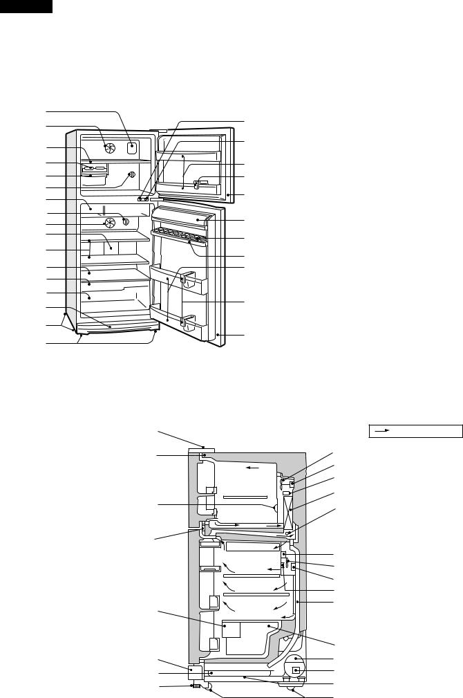
1. |
Freezer light(Lamp) |
|
1 |
18 |
2. |
Freezer fan |
|
2 |
3. |
Freezer shelf(F shelf ass'y) |
||
19 |
4. |
Ice cube maker |
||
3 |
5. |
Ice cube box(Ice storage box) |
||
|
6. |
Freezer temp. control knob |
||
4 |
20 |
7. |
Chilled case |
|
5 |
21 |
8. |
Refrigerator temp. control knob |
|
9. |
Refrigerator fan |
|||
6 |
22 |
|||
10. |
Refrigerator light(Lamp) |
|||
7 |
||||
|
11. |
Refrigerator shelf(R glass shelf ass'y) |
||
8 |
|
|||
23 |
|
(SJ-58L/63L; 2 shelves, SJ-68L; 3 shelves) |
||
9 |
12. |
Shelf(V glass shelf ass'y) |
||
|
||||
10 |
24 |
13. |
Fruit case |
|
11 |
14. |
Vegetable crisper(Vegetable case) |
||
25 |
||||
|
15. |
Evaporating pan & cover |
||
12 |
26 |
16. |
Caster |
|
13 |
|
17. |
Adjustable feet(Adjustable leg ass'y) |
|
14 |
27 |
18. |
Fan & light switch(for freezer) |
|
15 |
19. |
Fan & light switch(for refrigerator) |
||
|
20. |
Freezer pocket(F door pocket) |
||
|
|
|||
16 |
22 |
21. |
Water cup |
|
17 |
22. |
Magnetic door seal(Door packing) |
||
|
23. |
Utility pocket(Utility case pocket) |
||
|
|
24. |
Egg holder(Egg tray) |
|
|
Figure D-1. External Description |
25. |
Free pocket(R door pocket) |
|
|
|
(SJ-58L/63L; 1 pocket, SJ-68L; 2 pockets) |
||
|
|
|
||
|
|
26. |
Bottle pocket |
|
|
|
27. |
Bottle guard(Tube stand) |
|
Upper hinge cover |
Mark: Cold air flow |
Hot pipe |
Freezer fan |
|
Fan motor |
Freezer |
Defrost thermostat |
compartment |
Evaporator |
|
|
Freezer temp. control knob |
Defrost heater |
|
|
Hot pipe |
|
Refrigerator |
Timer, R-fan themo. ass’y |
compartment |
Refrigerator fan |
|
Damper thermostat |
|
Refrigerator temp. control knob |
|
Drain pipe |
Fruit case |
|
|
Vegetable case |
Ventilating grille |
Compressor |
Evaporating pan |
Starting relay, Overload relay(Protector) |
|
|
Adjustable leg ass’y |
Sub condenser |
|
|
|
Caster |

 This figure shows SJ-63L .
Figure D-2. Constructions
4

SJ-58L-A2
SJ-63L-A2
SJ-68L-A2
LIST OF ELECTRICAL PARTS
ITEMS |
|
|
|
|
|
|
|
|
|
|
|
|
TYPE NAME |
|
|
|
|
RATING |
|
|
|
|
|
|
|
|
SPECIFICATIONS |
|
|
|
|
|
||||||||||||||||||||||||||||||||||||||
Thermostat |
|
MM1-8123 |
125V |
6A |
|
(At normal notch) |
|
|
|
|
|
|
|
|
|
|
|
|||||||||||||||||||||||||||||||||||||||||||||||||||||
|
|
|
|
|
|
|
|
|
|
|
|
|
|
|
|
|
|
|
|
|
|
|
|
|
250V |
3A |
|
ON/OFF : -19/-24˚C |
|
|
|
|
|
|
|
|
|
|
|
|||||||||||||||||||||||||||||||
Defrost thermostat |
|
S101 |
250V |
8A |
|
Open/Close : 10/1˚C |
|
|
|
|
|
|
|
|
|
|
|
|||||||||||||||||||||||||||||||||||||||||||||||||||||
Thermo. fuse |
|
SF70E |
250V |
10A |
|
Working temp. : 70˚C |
|
|
|
|
|
|
|
|
|
|
|
|||||||||||||||||||||||||||||||||||||||||||||||||||||
F-fan motor |
|
3R00044B |
220-240V 50/60Hz |
|
Working with ø100 fan |
|
|
|
|
|
|
|
|
|
|
|
||||||||||||||||||||||||||||||||||||||||||||||||||||||
R-fan motor |
|
|
|
|
|
|
|
|
3R00122A |
220-240V 50/60Hz |
|
Working with ø80 fan |
|
|
|
|
|
|
|
|
|
|
|
|||||||||||||||||||||||||||||||||||||||||||||||
|
|
|
|
|
|
|
|
|
|
|
|
|
|
|
|
|
|
|
|
|
|
|
|
|
|
|
|
|
|
|
|
|
|
|
|
|
|
|
|
|
|
|
|
|
|
|
|
|
|
|
|
|
|
|
|
|
|
|
|
|
|
|
|
|
|
|
|
|
|
|
|
|
(R-fan fuse) |
123 |
|
|
|
|
|
|
|
|
|
|
|
250V |
2A |
|
Cut OFF 130˚C |
|
|
|
|
|
|
|
|
|
|
|
|||||||||||||||||||||||||||||||||||||||||
Defrost heater |
|
MM6-4198 |
220-240V 353Ω |
|
150W at 230V |
|
|
|
|
|
|
|
|
|
|
|
||||||||||||||||||||||||||||||||||||||||||||||||||||||
Door switch |
|
DSD-5 |
250V |
0.25A |
|
4 terminals push-button type |
|
|
|
|
|
|||||||||||||||||||||||||||||||||||||||||||||||||||||||||||
Damper thermostat |
|
MM1-6170 |
— |
|
|
|
|
|
|
|
|
|
|
|
Open/Close : 3/-2˚C |
|
|
|
|
|
|
|
|
|
|
|
||||||||||||||||||||||||||||||||||||||||||||
Defrost timer |
|
TMDF904FD2 |
220-240V |
|
Integration type |
|
|
|
|
|
|
|
|
|
|
|
||||||||||||||||||||||||||||||||||||||||||||||||||||||
|
|
|
|
|
|
|
|
|
|
|
|
|
|
|
|
|
|
|
|
|
|
|
|
|
50/60Hz |
|
Cycle time : 10.8/9.0 hours(50/60Hz) |
|||||||||||||||||||||||||||||||||||||||||||
|
|
|
|
|
|
|
|
|
|
|
|
|
|
|
|
|
|
|
|
|
|
|
|
|
|
|
|
|
|
|
|
|
|
|
|
|
|
|
|
|
Delay time : 4.3/3.6 min.(50/60Hz) |
|
|
|
|
|
||||||||||||||||||||||||
|
|
|
|
|
|
|
|
|
|
|
|
|||||||||||||||||||||||||||||||||||||||||||||||||||||||||||
Lamp socket (F/R) |
|
— |
250V |
1A |
|
E-12(Hard plastic body type) |
|
|
|
|
|
|||||||||||||||||||||||||||||||||||||||||||||||||||||||||||
F-lamp |
|
|
|
|
|
|
|
|
|
— |
240V |
10W |
|
E-12 |
|
|
|
|
|
|
|
|
|
|
|
|||||||||||||||||||||||||||||||||||||||||||||
|
|
|
|
|
|
|
|
|
|
|
|
|
|
|
|
|
|
|
|
|
|
|
|
|
|
|||||||||||||||||||||||||||||||||||||||||||||
R-lamp |
|
|
|
|
|
|
|
|
|
— |
240V |
15W |
|
E-12 |
|
|
|
|
|
|
|
|
|
|
|
|||||||||||||||||||||||||||||||||||||||||||||
R-fan thermo. |
R-fan thermo. |
|
S101 |
250V |
8A |
|
Open/ Close : 7/15˚C |
|
|
|
|
|
|
|
|
|
|
|
||||||||||||||||||||||||||||||||||||||||||||||||||||
ass'y |
R-fan thermo.heater |
|
RSS2 |
350V, |
2W, 10kΩ |
|
1.1W at 230V |
|
|
|
|
|
|
|
|
|
|
|
||||||||||||||||||||||||||||||||||||||||||||||||||||
SJ-58L,63L |
|
|
|
|
|
|
|
|
|
|
|
|
|
|
|
|
|
|
|
|
|
|
|
|
|
|
|
|
|
|
|
|
|
|
|
|
|
|
|
|
|
|
|
|
|
|
|
|
|
|
|
|
|
|
|
|
|
|
|
|
|
|
||||||||
Compressor |
|
GLY80AA |
220-240V/50Hz |
|
Cooling capacity : 197kcal/h(50Hz) |
|
|
|
|
|
||||||||||||||||||||||||||||||||||||||||||||||||||||||||||||
|
|
|
|
|
|
|
|
|
|
|
|
|
|
|
|
|
|
|
|
|
|
|
|
|
|
|
|
|
|
|
|
|
|
|
|
|
|
|
|
|
Main coil : 10.3Ω |
Common |
|
|
|
|
|
|||||||||||||||||||||||
|
|
|
|
|
|
|
|
|
|
|
|
|
|
|
|
|
|
|
|
|
|
|
|
|
|
|
|
|
|
|
|
|
|
|
|
|
|
|
|
|
Aux. coil : 14.2Ω |
|
|
|
|
|
||||||||||||||||||||||||
|
|
|
|
|
|
|
|
|
|
|
|
|
|
|
|
|
|
|
|
|
|
|
|
|
|
|
|
|
|
|
|
|
|
|
|
|
|
|
|
|
|
|
|
|
|
|
|
|
|
|
|
|||||||||||||||||||
|
|
|
|
|
|
|
|
|
|
|
|
|
|
|
|
|
|
|
|
|
|
|
|
|
|
|
|
|
|
|
|
|
|
|
|
|
|
|
|
|
|
|
|
|
|
|
|
|
|
|
||||||||||||||||||||
|
|
|
|
|
|
|
|
|
|
|
|
|
|
|
|
|
|
|
|
|
|
|
|
|
|
|
|
|
|
|
|
|
|
|
|
|
|
|
|
|
(at 25˚C) |
|
|
|
|
|
|
|
|
|
|
|
||||||||||||||||||
|
|
|
|
|
|
|
|
|
|
|
|
|
|
|
|
|
|
|
|
|
|
|
|
|
|
|
|
|
|
|
|
|
|
|
|
|
|
|
|
|
|
|
|
|
|
|
|
|
|
|
||||||||||||||||||||
|
|
|
|
|
|
|
|
|
|
|
|
|
|
|
|
|
|
|
|
|
|
|
|
|
|
|
|
|
|
|
|
|
|
|
|
|
|
|
|
|
|
|
|
|
|
|
|
|
|
|
|
|
|
|
Aux. coil |
|
|
|
|
|
|
Main coil |
||||||||
|
|
|
|
|
|
|
|
|
|
|
|
|
|
|
|
|
|
|
|
|
|
|
|
|
|
|
||||||||||||||||||||||||||||||||||||||||||||
Starting relay |
|
UH3003-7 |
— |
|
|
|
|
|
|
|
|
|
|
|
14.0 Ω |
|
|
|
|
|
|
|
|
|
|
|
||||||||||||||||||||||||||||||||||||||||||||
Overload relay(Protector) |
|
4TM308NFBYY |
— |
|
|
|
|
|
|
|
|
|
|
|
Open/ Close : 120/61˚C |
|
|
|
|
|
|
|
|
|
|
|
||||||||||||||||||||||||||||||||||||||||||||
SJ-68L |
|
|
|
|
|
|
|
|
|
|
|
|
|
|
|
|
|
|
|
|
|
|
|
|
|
|
|
|
|
|
|
|
|
|
|
|
|
|
|
|
|
|
|
|
|
|
|
|
|
|
|
|
|
|
|
|
|
|
|
|
|
|
|
|
|
|
|
|
|
|
Compressor |
|
GLY90AA |
220-240V/50Hz |
|
Cooling capacity : 220kcal/h(50Hz) |
|
|
|
|
|
||||||||||||||||||||||||||||||||||||||||||||||||||||||||||||
|
|
|
|
|
|
|
|
|
|
|
|
|
|
|
|
|
|
|
|
|
|
|
|
|
|
|
|
|
|
|
|
|
|
|
|
|
|
|
|
|
Main coil : 8.8Ω |
Common |
|
|
|
|
|
|||||||||||||||||||||||
|
|
|
|
|
|
|
|
|
|
|
|
|
|
|
|
|
|
|
|
|
|
|
|
|
|
|
|
|
|
|
|
|
|
|
|
|
|
|
|
|
Aux. coil : 14.2Ω |
|
|
|
|
|
||||||||||||||||||||||||
|
|
|
|
|
|
|
|
|
|
|
|
|
|
|
|
|
|
|
|
|
|
|
|
|
|
|
|
|
|
|
|
|
|
|
|
|
|
|
|
|
|
|
|
|
|
|
|
|
|
|
|
|||||||||||||||||||
|
|
|
|
|
|
|
|
|
|
|
|
|
|
|
|
|
|
|
|
|
|
|
|
|
|
|
|
|
|
|
|
|
|
|
|
|
|
|
|
|
|
|
|
|
|
|
|
|
|
|
||||||||||||||||||||
|
|
|
|
|
|
|
|
|
|
|
|
|
|
|
|
|
|
|
|
|
|
|
|
|
|
|
|
|
|
|
|
|
|
|
|
|
|
|
|
|
(at 25˚C) |
|
|
|
|
|
|
|
|
|
|
|
||||||||||||||||||
|
|
|
|
|
|
|
|
|
|
|
|
|
|
|
|
|
|
|
|
|
|
|
|
|
|
|
|
|
|
|
|
|
|
|
|
|
|
|
|
|
|
|
|
|
|
|
|
|
|
|
||||||||||||||||||||
|
|
|
|
|
|
|
|
|
|
|
|
|
|
|
|
|
|
|
|
|
|
|
|
|
|
|
|
|
|
|
|
|
|
|
|
|
|
|
|
|
|
|
|
|
|
|
|
|
|
|
|
|
|
|
Aux. coil |
|
|
|
|
|
|
Main coil |
||||||||
|
|
|
|
|
|
|
|
|
|
|
|
|
|
|
|
|
|
|
|
|
|
|
|
|
|
|
||||||||||||||||||||||||||||||||||||||||||||
Starting relay |
|
UH3003-7 |
— |
|
|
|
|
|
|
|
|
|
|
|
14.0 Ω |
|
|
|
|
|
|
|
|
|
|
|
||||||||||||||||||||||||||||||||||||||||||||
Overload relay(Protector) |
|
4TM757NFBYY |
— |
|
|
|
|
|
|
|
|
|
|
|
Open/ Close : 120/61˚C |
|
|
|
|
|
|
|
|
|
|
|
||||||||||||||||||||||||||||||||||||||||||||
5

SJ-58L-A2
SJ-63L-A2
SJ-68L-A2
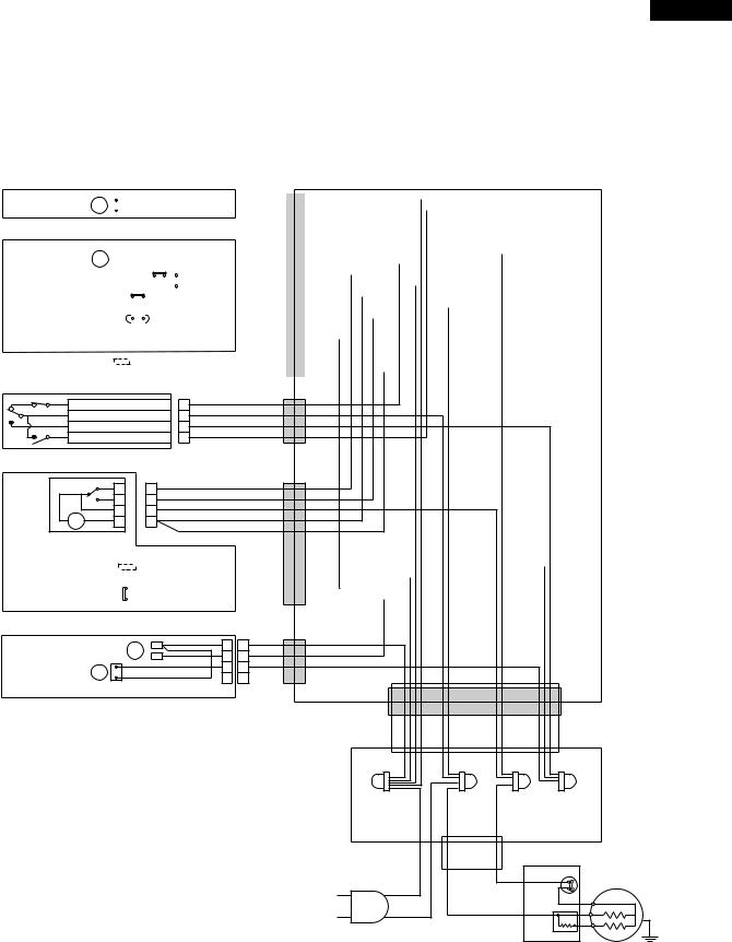
WIRING DIAGRAM
Be sure to replace the electrical parts with specified ones for maintaining the safety and performance of the set.
G |
: GRAY |
|
Br |
: BROWN |
|
O |
: ORANGE |
|
Y |
: YELLOW |
|
R |
: RED |
CONNECTED IN TERMINAL BOX |
P |
: PINK |
|
B |
: BLUE |
CONNECTOR |
Bk |
: BLACK |
|
S-B |
: SKY-BLUE |
|
G-Y : GREEN-YELLOW |
|
|
W |
: WHITE |
|
(BR) |
F-THERMOSTAT |
|
|
(G) |
|
|
|
|
|
|
(R) |
3 |
|
4 |
|
|
TM |
||
R |
F |
|
DEFROST |
|
|
|
|||
FM |
FM |
|
|
TIMER |
|
|
|
F |
R |
R-FAN THERMO. |
THERMO. 2 |
1 |
|
|
FUSE |
|
|
L |
L |
HEATER |
|
|
|
|
|
(W) |
(BK) |
|
(S-B) |
R-FAN |
(O) |
DEFROST |
|
|
|||
2 |
4 |
THERMO. |
3 |
HEATER |
|
|
|
|
PROTECTOR |
|
|
|
|
(Y) |
DOOR SWITCH 1 |
DEFROST |
COMPRESSOR |
|
C |
|
|
THERMOSTAT |
|
|
|
|
|
|
M |
|
(B) |
A |
|
|
|
|
|
STARTING RELAY |
Figure W-1. Wiring Diagram (2 pin plug region)
(BR) |
F-THERMOSTAT |
|
|
(G) |
|
|
|
|
|
|
(R) |
3 |
|
4 |
|
|
TM |
||
R |
F |
|
DEFROST |
|
|
|
|||
FM |
FM |
|
|
TIMER |
|
|
|
F |
R |
R-FAN THERMO. |
THERMO. 2 |
1 |
|
|
FUSE |
|
|
L |
L |
HEATER |
|
|
|
|
|
(W) |
(BK) |
|
(S-B) |
R-FAN |
(O) |
DEFROST |
|
|
|||
2 |
4 |
THERMO. |
3 |
HEATER |
|
|
|
|
PROTECTOR |
|
|
|
|
(Y) |
DOOR SWITCH 1 |
DEFROST |
COMPRESSOR |
|
C |
|
|
THERMOSTAT |
|
|
|
|
|
|
M |
|
(B) |
A |
|
|
|
|
|
STARTING RELAY |
Figure W-2. Wiring Diagram (3 pin plug region)
6
SJ-58L-A2
SJ-63L-A2
SJ-68L-A2
F LAMP BOX ASS’Y |
|
|
|
|
|
|
|
|
|
|
|
|
|
|
|
|
|
|
|
|
|
|
|
|
CABINET ASS’Y |
|
||||||||||
|
|
|
|
|
|
|
|
|
|
|
|
|
|
|
|
|
|
|
|
|
|
|
|
|
|
|
|
|
|
|
|
|
|
|
|
|
|
|
|
|
|
|
|
|
|
LAMP SOCKET |
|
|
|
BR-1 |
|
|
|
|
|
|
|
|
|
|
|
|
|
||||||||||
F-LAMP(10W) |
L |
|
|
|
|
|
|
|
|
|
|
|
|
|
|
|
|
1 |
|
1 |
W-2 |
|
|
|
|
|
|
|
|
|
|
|
|
|
||
|
|
|
|
|
|
|
|
|
|
|
|
|
|
|
|
2 |
|
2 |
|
|
|
|
|
|
|
|
|
|
|
|
|
|||||
|
|
|
|
|
|
|
|
|
|
|
|
|
|
|
|
|
|
|
|
|
|
|
|
|
|
|
|
|
|
|
||||||
E. V. COVER ASS’Y |
|
|
|
|
|
|
|
|
|
|
|
|
|
|
|
|
|
|
|
|
|
|
|
|
|
|
|
|
|
|
|
|
|
|
||
|
|
|
|
|
|
|
|
|
|
|
|
|
|
|
|
|
|
|
|
|
|
|
|
|
|
|
|
|
|
|
|
|
|
|
|
|
|
|
|
|
|
|
LEAD EV-COVER ASS’Y |
|
|
|
GY-1 |
|
|
|
|
|
|
|
|
|
|
|
|
|
|||||||||||||
F-FAN MOTOR FM |
|
|
|
|
|
|
|
|
|
|
|
|
|
|
1 |
|
1 |
OR-1 |
|
|
|
|
|
|
|
|
|
|
|
|
|
|||||
|
|
|
|
|
|
|
|
|
|
|
|
|
2 |
|
2 |
|
|
|
|
|
|
|
|
|
|
|
|
|
||||||||
|
|
|
|
|
|
|
|
|
|
|
|
|
|
|
|
|
|
|
|
3 |
|
3 |
R-1 |
|
|
|
|
|
|
|
|
|
|
|
|
|
F-THERMOSTAT |
|
|
|
|
|
|
|
|
|
|
|
|
|
|
|
|
|
|
|
4 |
|
4 |
BR-2 |
|
|
|
|
|
|
|
|
|
|
|
|
|
|
|
|
|
|
|
|
|
|
|
|
|
|
|
|
|
|
|
|
|
|
|
|
|
|
|
|
|
|
|
|
|
|
||||
|
|
|
|
|
|
|
|
|
|
|
|
|
|
|
|
|
|
|
|
Y-1 |
|
|
|
|
|
|
|
|
|
|
|
|
|
|||
|
|
|
|
|
|
|
|
|
|
|
|
|
|
|
|
|
|
|
|
|
|
|
|
|
|
|
|
|
|
|
|
|
|
|
|
|
DEF. THERMO. ASS’Y |
|
|
|
|
|
|
|
|
|
|
|
|
|
|
|
|
5 |
|
5 |
BL-1 |
|
|
|
|
|
|
|
|
|
|
|
|
|
|||
|
|
|
|
|
|
|
|
|
6 |
|
6 |
|
|
|
|
|
|
|
|
|
|
|
|
|
||||||||||||
|
|
|
|
|
|
|
|
|
|
|
|
|
|
|
|
|
|
|
|
|
BK-1 |
|
|
|
|
|
|
|
|
|
|
|
|
|
||
FUSE ASS’Y |
|
|
|
|
|
|
|
|
|
|
|
|
|
|
|
|
|
|
|
7 |
|
7 |
W-1 |
|
|
|
|
|
|
|
|
|
|
|
|
|
|
|
|
|
|
|
|
|
|
|
|
|
|
|
|
|
|
|
|
8 |
|
8 |
|
|
|
|
|
|
|
|
|
|
|
|
|
||
|
|
|
|
|
|
|
|
|
|
|
|
|
|
|
|
|
|
|
|
9 |
|
9 |
OR-3 |
|
|
|
|
|
|
|
|
|
|
|
|
|
|
|
|
|
|
|
|
|
|
|
|
|
|
|
|
|
|
|
|
|
|
(W-1) |
|
|
|
|
|
|
|
|
|
|
|
|
|
||
|
|
|
|
|
|
|
|
|
|
|
|
|
|
|
|
|
|
|
|
|
|
|
|
|
|
|
|
|
|
|
|
|
|
|
|
|
DEF. HEATER ASS’Y |
|
|
|
|
|
|
|
|
|
|
|
|
|
|
|
|
|
|
1 |
|
1 |
Y-2 |
|
|
|
|
|
|
|
|
|
|
|
|
|
|
|
|
|
|
|
|
|
|
|
|
|
|
|
2 |
|
2 |
|
|
|
|
|
|
|
|
|
|
|
|
|
||||||||
|
|
|
|
|
|
|
|
|
|
|
|
|
|
|
|
|
|
|
|
|
|
|
|
|
|
|
|
|
|
|
|
|
|
|
||
DOOR SWITCH |
|
|
|
|
3 (PUSH CLOSE) |
|
3 |
(OR-1) |
|
|
BL-2 |
|||
1 (NEUTRAL) |
|
1 |
||
|
SB-1 |
|||
4 (PUSH OPEN) |
|
4 |
||
|
(W-2) |
|||
2 (PUSH OPEN) |
|
2 |
||
|
|
|||
R CONTROL COV. ASS’Y |
|
|
|
|
|
3 |
3 |
|
(R-1) |
|
|
(BK-1) |
||
|
2 |
2 |
|
|
|
|
GY-2 |
||
|
4 |
4 |
|
|
|
|
(Y-1) |
||
TM |
1 |
1 |
|
|
|
(Y-2) |
|||
|
|
|
|
|
DEFROST TIMER |
|
|
|
|
(R-FAN |
|
|
|
|
|
|
|
|
|
|
|
|
|
|
SB-2 |
|
||
THERMO. HEATER) |
|
|
|
|
|
|
|
|
|
|
|
1 |
|
1 |
BR-3 |
|
||
|
|
|
|
|
2 |
|
2 |
|
||||||||||
|
|
|
|
|
|
|
|
|
|
|
|
OR-3 |
|
|
|
|||
R FAN THERMO. |
|
|
|
|
|
|
|
|
|
|
|
3 |
|
3 |
|
|
||
|
|
|
|
|
|
|
|
|
|
|
|
|
|
|||||
|
|
|
|
|
OR-2 |
|
|
|||||||||||
4 |
|
4 |
|
|
||||||||||||||
|
|
|
|
|
|
|
|
|
|
|
|
|
|
|
||||
|
|
|
|
|
|
|
|
|
|
|
|
|
|
|
||||
|
|
|
|
|
|
|
|
|
|
|
|
|
|
|
|
|
||
R LAMP BOX ASS’Y |
|
|
|
|
|
|
|
R-FAN MOTOR |
FM |
1 |
1 |
BR-4 |
|
|
|
2 |
2 |
(OR-2) |
|
|
|||
|
|
|
|
||||
R-LAMP (15W) |
L |
3 |
3 |
SB-3 |
|
|
|
4 |
4 |
|
|
|
|||
|
|
LAMP SOCKET |
|
|
|
||
|
|
|
|
|
|
|
|
|
|
|
|
|
|
|
TERMINAL BOX |
|
|
|
|
|
BROWN |
BLUE |
GRAY |
G |
: GRAY |
|
|
|
|
|
SKY-BLUE |
Br |
: BROWN |
|
|
|
|
|
|
O |
: ORANGE |
|
|
|
|
|
|
Y |
: YELLOW |
|
|
|
|
|
|
R |
: RED |
|
|
|
|
|
|
P |
: PINK |
|
|
|
|
|
|
B |
: BLUE |
|
|
|
|
|
PROTECTOR |
Bk |
: BLACK |
|
|
|
|
COMPRESSOR |
|
|
|
|
|
|
|||
S-B : SKY-BLUE |
|
|
|
|
C |
||
G-Y : GREEN-YELLOW |
|
|
|
|
M |
||
|
|
|
|
|
|
|
|
W |
: WHITE |
|
|
|
|
A |
|
|
|
SOURCE CORD |
|
STARTING RELAY |
|||
|
|
|
|
|
|
||
|
|
|
|
|
|
|
TERMINAL COVER |
Figure W-3. Electric Accessories Layout (2 pin plug region)
7

SJ-58L-A2
SJ-63L-A2
SJ-68L-A2
F LAMP BOX ASS’Y |
|
|
|
|
|
|
|
|
|
|
|
|
|
|
|
|
|
|
|
|
|
|
|
|
CABINET ASS’Y |
|
||||||||||
|
|
|
|
|
|
|
|
|
|
|
|
|
|
|
|
|
|
|
|
|
|
|
|
|
|
|
|
|
|
|
|
|
|
|
|
|
|
|
|
|
|
|
|
|
|
LAMP SOCKET |
|
|
|
BR-1 |
|
|
|
|
|
|
|
|
|
|
|
|
|
||||||||||
F-LAMP(10W) |
L |
|
|
|
|
|
|
|
|
|
|
|
|
|
|
|
|
1 |
|
1 |
W-2 |
|
|
|
|
|
|
|
|
|
|
|
|
|
||
|
|
|
|
|
|
|
|
|
|
|
|
|
|
|
|
2 |
|
2 |
|
|
|
|
|
|
|
|
|
|
|
|
|
|||||
|
|
|
|
|
|
|
|
|
|
|
|
|
|
|
|
|
|
|
|
|
|
|
|
|
|
|
|
|
|
|
||||||
E. V. COVER ASS’Y |
|
|
|
|
|
|
|
|
|
|
|
|
|
|
|
|
|
|
|
|
|
|
|
|
|
|
|
|
|
|
|
|
|
|
||
|
|
|
|
|
|
|
|
|
|
|
|
|
|
|
|
|
|
|
|
|
|
|
|
|
|
|
|
|
|
|
|
|
|
|
|
|
|
|
|
|
|
|
LEAD EV-COVER ASS’Y |
|
|
|
GY-1 |
|
|
|
|
|
|
|
|
|
|
|
|
|
|||||||||||||
F-FAN MOTOR FM |
|
|
|
|
|
|
|
|
|
|
|
|
|
|
1 |
|
1 |
OR-1 |
|
|
|
|
|
|
|
|
|
|
|
|
|
|||||
|
|
|
|
|
|
|
|
|
|
|
|
|
2 |
|
2 |
|
|
|
|
|
|
|
|
|
|
|
|
|
||||||||
|
|
|
|
|
|
|
|
|
|
|
|
|
|
|
|
|
|
|
|
3 |
|
3 |
R-1 |
|
|
|
|
|
|
|
|
|
|
|
|
|
F-THERMOSTAT |
|
|
|
|
|
|
|
|
|
|
|
|
|
|
|
|
|
|
|
4 |
|
4 |
BR-2 |
|
|
|
|
|
|
|
|
|
|
|
|
|
|
|
|
|
|
|
|
|
|
|
|
|
|
|
|
|
|
|
|
|
|
|
|
|
|
|
|
|
|
|
|
|
|
||||
|
|
|
|
|
|
|
|
|
|
|
|
|
|
|
|
|
|
|
|
Y-1 |
|
|
|
|
|
|
|
|
|
|
|
|
|
|||
|
|
|
|
|
|
|
|
|
|
|
|
|
|
|
|
|
|
|
|
|
|
|
|
|
|
|
|
|
|
|
|
|
|
|
|
|
DEF. THERMO. ASS’Y |
|
|
|
|
|
|
|
|
|
|
|
|
|
|
|
|
5 |
|
5 |
BL-1 |
|
|
|
|
|
|
|
|
|
|
|
|
|
|||
|
|
|
|
|
|
|
|
|
6 |
|
6 |
|
|
|
|
|
|
|
|
|
|
|
|
|
||||||||||||
|
|
|
|
|
|
|
|
|
|
|
|
|
|
|
|
|
|
|
|
|
|
|
BK-1 |
|
|
|
|
|
|
|
|
|
|
|
|
|
FUSE ASS’Y |
|
|
|
|
|
|
|
|
|
|
|
|
|
|
|
|
|
|
|
7 |
|
7 |
W-1 |
|
|
|
|
|
|
|
|
|
|
|
|
|
|
|
|
|
|
|
|
|
|
|
|
|
|
|
|
|
|
|
|
8 |
|
8 |
|
|
|
|
|
|
|
|
|
|
|
|
|
||
|
|
|
|
|
|
|
|
|
|
|
|
|
|
|
|
|
|
|
|
9 |
|
9 |
OR-3 |
|
|
|
|
|
|
|
|
|
|
|
|
|
|
|
|
|
|
|
|
|
|
|
|
|
|
|
|
|
|
|
|
|
|
(W-1) |
|
|
|
|
|
|
|
|
|
|
|
|
|
||
|
|
|
|
|
|
|
|
|
|
|
|
|
|
|
|
|
|
|
|
|
|
|
|
|
|
|
|
|
|
|
|
|
|
|
|
|
DEF. HEATER ASS’Y |
|
|
|
|
|
|
|
|
|
|
|
|
|
|
|
|
|
|
1 |
|
1 |
Y-2 |
|
|
|
|
|
|
|
|
|
|
|
|
|
|
|
|
|
|
|
|
|
|
|
|
|
|
|
2 |
|
2 |
|
|
|
|
|
|
|
|
|
|
|
|
|
||||||||
|
|
|
|
|
|
|
|
|
|
|
|
|
|
|
|
|
|
|
|
|
|
|
|
|
|
|
|
|
|
|
|
|
|
|
||
DOOR SWITCH |
|
|
|
|
3 (PUSH CLOSE) |
|
3 |
(OR-1) |
|
|
BL-2 |
|||
1 (NEUTRAL) |
|
1 |
||
|
SB-1 |
|||
4 (PUSH OPEN) |
|
4 |
||
|
(W-2) |
|||
2 (PUSH OPEN) |
|
2 |
||
|
|
|||
R CONTROL COV. ASS’Y |
|
|
|
|
|
3 |
3 |
|
(R-1) |
|
|
(BK-1) |
||
|
2 |
2 |
|
|
|
|
GY-2 |
||
|
4 |
4 |
|
|
|
|
(Y-1) |
||
TM |
1 |
1 |
|
|
|
(Y-2) |
|||
|
|
|
|
|
DEFROST TIMER |
|
|
|
|
(R-FAN |
|
|
|
|
|
|
|
|
|
|
|
SB-2 |
|
||
THERMO. HEATER) |
|
|
|
|
|
|
|
|
1 |
|
1 |
BR-3 |
|
||
|
|
|
|
|
|
|
|
|
|||||||
2 |
|
2 |
|
||||||||||||
|
|
|
|
|
|
|
|
|
OR-3 |
|
|
|
|||
R FAN THERMO. |
|
|
|
|
|
|
|
|
3 |
|
3 |
|
|
||
|
|
|
|
|
|
|
|
|
|
|
|||||
|
|
|
|
|
OR-2 |
|
|
||||||||
4 |
|
4 |
|
|
|||||||||||
|
|
|
|
|
|
|
|
|
|
|
|
||||
|
|
|
|
|
|
|
|
|
|
|
|
||||
|
|
|
|
|
|
|
|
|
|
|
|
|
|
||
R LAMP BOX ASS’Y |
|
|
|
|
|
|
|
|
|
R-FAN MOTOR |
FM |
1 |
1 |
BR-4 |
|
|
|
|
|
2 |
2 |
(OR-2) |
|
|
|
|
|||
|
|
|
|
|
|
||||
R-LAMP (15W) |
L |
3 |
3 |
SB-3 |
|
|
|
|
|
4 |
4 |
|
|
|
|
|
|||
|
|
LAMP SOCKET |
|
|
|
|
|
||
|
|
|
|
|
|
|
|
|
|
|
|
|
|
|
|
|
|
TERMINAL BOX |
|
|
|
|
|
|
BROWN |
BLUE |
GRAY |
|
|
G |
: GRAY |
|
|
|
|
|
|
SKY-BLUE |
|
Br |
: BROWN |
|
|
|
|
|
|
||
|
|
|
EARTH |
|
|
|
|||
O |
: ORANGE |
|
|
|
|
|
|
||
|
|
|
|
|
|
|
|||
Y |
: YELLOW |
|
|
|
|
|
|
|
|
R |
: RED |
|
|
|
|
|
|
|
|
P |
: PINK |
|
|
|
|
|
|
|
|
B |
: BLUE |
|
|
|
|
|
PROTECTOR |
|
|
Bk |
: BLACK |
|
|
|
|
|
1 |
|
COMPRESSOR |
S-B |
: SKY-BLUE |
|
|
|
|
L |
|
C |
|
|
|
|
|
E |
|
||||
G-Y : GREEN-YELLOW |
|
|
|
|
M |
||||
|
|
|
|
N |
|||||
W |
: WHITE |
|
|
|
|
|
|
A |
|
|
|
|
|
|
|
|
|||
|
|
|
|
|
SOURCE CORD |
|
STARTING RELAY |
|
|
|
|
|
|
|
|
|
TERMINAL COVER |
|
|
Figure W-4. Electric Accessories Layout (3 pin plug region)
8

SJ-58L-A2
SJ-63L-A2
SJ-68L-A2
FUNCTIONS
1.ADJUSTABLE TEMPERATURE CONTROL
(1)Temperature control of freezer
 Thermostat (senses freezer temperature) operates on ON/OFF switchover to control the compressor and cool air circulating fan (F-fan motor) , and allows the freezer temperature to keep at a suitable temperature.
  However adjust the freezer temp. control knob as follows depending upon the storing condition of foods.
|
|
MED |
|
|
KNOB |
PURPOSE |
||||||
3 |
4 |
|
5 |
6 |
||||||||
|
|
|
|
|
SETTING |
|
||||||
2 |
|
|
|
|
|
7 |
|
|||||
|
|
|
|
|
|
|||||||
1 |
|
|
|
|
|
MAX(Coldest) |
For making ice rapidly or fast freezing. |
|||||
|
MIN |
|
|
|
|
|
MAX |
|||||
|
|
|
|
|
|
|
Coldest |
|
|
|
When restocking with fresh food. |
|
|
|
|
|
|
|
|
|
|
|
|
||
|
|
|
|
|
|
|
|
|
|
|||
|
|
|
|
|
|
|
|
MED |
For normal freezing. |
|||
|
|
|
|
|
|
|
|
|||||
|
|
|
|
|
|
|
|
|
|
|
|
|
|
|
|
|
|
|
|
|
|
|
|
For storing frozen food for a short period (up to one month). |
|
|
|
|
|
|
|
|
|
|
|
|
||
|
|
|
|
|
|
|
|
|
|
|
||
FREEZER TEMP. CONTROL |
|
|
|
|||||||||
|
|
|
|
|||||||||
MIN |
When frozen food or ice cream is not stored. |
|||||||||||
|
Figure F-1. |
|||||||||||
|
|
|
|
|
||||||||
(2) Temperature control of refrigerator
 Damper-thermostat senses temperature of the refrigerator and changes the opening angle of the damper automatically.
However, as the Damper-thermostat has no function to switch on or off the compressor and F-fan motor, the freezer temperature control causes temperature in the refrigerator to vary to some extent.
 However, adjust the refrigerator temp. control knob as follows depending upon the cooling condition.
|
|
|
MED |
KNOB |
PURPOSE |
|||||
|
|
|
4 |
|
SETTING |
|
||||
3 |
|
|
|
5 |
|
|||||
|
|
|
|
CHILLED |
For keeping freshness of food longer. |
|||||
|
|
|
|
|
|
|
||||
2 |
|
|
|
6 |
ZONE |
|
||||
|
|
|
(Coldest) |
|
||||||
|
|
|
|
|
|
CHILLED |
|
|
|
|
|
|
|
|
|
|
When the refrigerator does not provide sufficient cooling. |
||||
|
|
MIN 1 |
|
|
|
ZONE |
|
|
|
|
|
|
|
|
|
7 Coldest |
MED |
For normal operation. |
|||
|
|
|
||||||||
|
|
|
|
|
|
|
|
|
|
|
REFRIGERATOR TEMP. CONTROL |
|
|
|
When the refrigerator provides excessive cooling. |
||||||
|
|
|
||||||||
|
|
|
||||||||
|
|
|
|
|
|
|
|
|
||
|
|
|
Figure F-2. |
MIN |
|
|||||
 When the temperature of the refrigerator is higher, R-fan thermo. senses the temperature and the refrigerator is cooled efficiently by running of R-fan motor.
R-fan thermo. heater energizes when the door is opened intend to promote to running of R-fan motor.
NOTE:  The refrigerator temperature is affected also by the freezer temperature. If the freezer temp. control knob is set at the position "MAX", the temperature tends to be lower than the following values, and if set at near the position "MIN", temperature tends to be higher.
 If the refrigerator is operated for a long time with the freezer temperature control sets the "MAX" position, foods stored in the refrigerator compartment may also freeze.
 When refrigerator temperature control sets to the "CHILLED ZONE", some foods stored may freeze.
In this case adjust control set back to the "MED" position.
 When refrigerator temperature control sets to the "CHILLED ZONE", some foods stored in chilled case may also become frozen.
(3) Reference value of temperature
SETTING OF |
MAX |
MED |
MIN |
FREEZER TEMP. |
|||
CONTROL KNOB |
(Coldest) |
|
|
Freezer |
Approx. |
Approx. |
Approx. |
temperature |
-21˚C |
-18˚C |
-15˚C |
|
|
|
|
SETTING OF |
CHILLED |
|
|
REFRIGERATOR TEMP. |
ZONE |
MED |
MIN |
CONTROL KNOB |
(Coldest) |
|
|
Refrigerator |
Approx. |
Approx. |
Approx. |
temperature |
0˚c |
3˚c |
6˚c |
|
|
|
|
Chilled room |
Approx. |
Approx. |
Approx. |
temperature |
-3˚c |
1˚c |
4˚c |
|
|
|
|
The values shown above refer to the case where the freezer temp. control knob is set at "MED".
The values shown above refer to the measurement carried out center area and 1/3 of overall height from the bottom at each of the refrigerator and the freezer after machine has been operated at an ambient temperature of 30˚C with no food stored and the door closed until the temperature is stabilized.
The values vary depending upon frequency of opening and closing the door, ambient temperature, amount of stored foods and manner of storing foods.
9

SJ-58L-A2
SJ-63L-A2
SJ-68L-A2
2. DEFROSTING |
|
(1) No defrosting operation is necessary |
(2) Where is melted frost brought |
No defrosting operation is necessary.
As this machine is so designed that a built-in evaporator cools air and a fan circulates cooled air, neither the freezer nor the refrigerator is frosted, though the evaporator is frosted.
The frosted evaporator is defrosted automatically due to the function of defrosting timer and heater, requiring no defrosting operation.
1.Melted frost is brought into the evaporating pan at the bottom of the set and is evaporated here by the heat of sub condenser.
2.Be sure that the evaporating pan is inserted correctly and is level.
(3)The following circuit diagrams in the table show automatic defrosting function of the refrigerator with timer and defrost thermostat.
Operation |
Electric diagram |
|
|
|
Description |
|
1. Cooling |
Defrost thermostat ON |
Compressor running |
|
The integration timer integrates running |
||
(Normal) |
|
Timer motor running |
|
time of the compressor. When it reaches |
||
|
Thermostat |
Timer contact |
|
|
cycle time of defrost timer, the timer |
|
UOSR C E |
|
|
|
remiTm o t o r |
r |
contact is changed to start defrosting. |
Defrost |
|
|
moCp r e s s o |
|
||
|
Thermo. fuse |
|
|
|
|
|
|
Defrost heater |
TM |
COMP |
|
|
|
|
thermostat (ON) |
|
|
|
|
|
|
Figure F-3. |
|
|
|
|
|
2. Defrosting |
Defrost thermostat ON |
Compressor stops |
|
The timer contact is changed to start |
||
(Time 20 to 30 min.) |
|
Timer motor stops |
|
defrosting, the timer motor stops, and |
||
|
Thermostat |
Timer contact |
|
|
power is supplied to the defrost heater. |
|
RUOSC E |
Defrost |
|
|
remiTm o t o r |
r |
It takes about 20 to 30 min. to defrost. |
|
|
pmoCr e s s o |
When little frosted, the defrosting takes |
|||
|
Thermo. fuse |
|
|
|
||
|
Defrost heater |
TM |
COMP |
|
little time. When much frosted, the def- |
|
|
|
|
|
rosting takes much time. |
||
|
|
|
|
|
|
|
|
thermostat (ON) |
|
|
|
|
|
|
Figure F-4 . |
|
|
|
|
|
3. Drain |
Defrost thermostat OFF |
Compressor stops |
|
When the defrost thermostat becomes |
||
(Time approx. 5 min.) |
|
Timer motor running |
|
OFF, the timer motor starts running. |
||
|
Thermostat |
Timer contact |
|
|
During the operation time (delay time |
|
|
|
|
|
remiTm o t o r |
r |
of defrost time) defrosted water is |
UOSR C E |
Defrost |
|
|
moCp r e s so |
drained outside the refrigerator. |
|
|
Thermo. fuse |
|
|
|
||
|
Defrost heater |
TM |
COMP |
|
|
|
|
thermostat (OFF) |
|
|
|
|
|
|
Figure F-5. |
|
|
|
|
|
4. Restart |
Defrost thermostat OFF |
Compressor running |
|
Timer contact is changed to cooling |
||
(Time approx. 5 min.) |
|
Timer motor stops |
|
operation and the compressor starts |
||
|
Thermostat |
Timer contact |
|
|
running and the timer motor stops. |
|
|
|
|
|
remiTm o t o r |
r |
Defrost thermostat contact becomes ON |
RUOSC E |
Defrost |
|
|
pmoCr e s so |
when it’s cooled. And the timer motor |
|
|
Thermo. fuse |
|
|
|
||
|
Defrost heater |
TM |
COMP |
|
starts running. (Figure F-3.) |
|
|
thermostat (OFF) |
|
|
|
|
|
|
Figure F-6. |
|
|
|
|
|
10
SJ-58L-A2
SJ-63L-A2
SJ-68L-A2
(4)As a reference to determine the causes of trouble, malfunction and phenomena are described below. Refer to the following when repairing.
1.Disconnection of defrost heater
As off-cycle defrosting is performed, the defrosting time is extremely prolonged. Each time defrosting is started, the freezer temperature rises and a portion of ice and stored foods are melted.
2.Melted thermo. fuse or opened-circuit due to the defect of defrost thermostat.
When the above mentioned trouble occurs in cooling operation, the timer motor does not run, defrosting will not take place, and consequently freezing is caused. In the above mentioned condition, when the timer shaft is turned by hand to defrost, the timer motor runs during the operation time. However, the motor stops from the time when the contact is changed, and freezing causes.
NOTE:
As the thermo. fuse assembly is intended to prevent dangers, do not use it under shorted condition even for a short period.
3.DEW PREVENTION
The hot pipe, namely D.P.-condenser, is arranged around the flange part of cabinet and the C-partition plate, preventing dew from being generated on the cabinet.
NOTE:
 D.P.-condenser pipe may be felt hot if touched by hand while the
compressor is in operation.
 If you are asked about this, please explain that the hot pipe serve to Hot pipe
  prevent the dew generation.
Figure F-7
4.INSPECTION OF INITIAL STARTING
(1)Inspection of cooling unit
1.Set the temperature control knob to "MAX" and check that the compressor starts to operate.
2.Depress the door switch to run the fan and check that cool air is blown out of the cold air outlet of the freezer and the refrigerator.
3.When the compressor does not work, check that the timer is not set to "defrost" position.
4 It takes about an hour and a half or two hours to put food in the refrigerator after starting operation.
NOTE:
 After return the temperature control knob to "MED" position.
 When the refrigerator is operated initially after installed, the compressor may vibrate excessively for 1 to 2 min. However, vibration becomes normal if it is continuously operated.
(2)Inspection of defrost device
Operate the refrigerator for 20 to 30 min. and then check the defrost device in the following procedures : Allow 5 min. to restart the compressor since immediate starting after stopping will cause unsmooth operation.
1.Turn the timer shaft clockwise with a screw driver.
At this time, make certains the timer clinks and the compressor stops.
2.After more than 5 min., turn the shaft further to operate. Make certain cooling operation is started again.
11
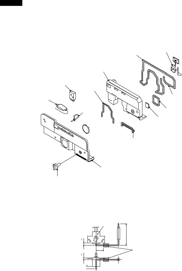
SJ-58L-A2
SJ-63L-A2
SJ-68L-A2
ASSEMBLING PROCEDURES OF MAIN PARTS AND CAUTIONS
CAUTION: DISCONNECT THE UNIT FROM THE POWER SUPPLY BEFORE ANY REPAIRING.
1. R-CONTROL COV. ASSEMBLY
Damper thermo.
|
RA sealer A |
R air guider A |
|
Defrost timer |
|
RA sealer D |
|
R fan thermo. ass’y |
RA sealer C |
|
|
Nylon band |
RA sealer B |
|
Dial sealer |

 Fan cover
A sealer thermo. cap.
R-C box cover
R-temp. control knob
Figure A-1
(1) Forming sensor of Damper thermo.
|
Damper |
|
thermostat |
mm |
|
1 |
|
+ |
|
3 |
|
mm |
25+2 mm |
1 |
|
+ |
|
5
Less than 12 mm
Less than 130 mm
Stick thermo. cap. sealer
NOTE
 Minimum bending radius is R5mm.
 There should be no gas leak by reforming of sensor tube.
Figure A-2
After forming, fix it to the refrigerator.
12

SJ-58L-A2
SJ-63L-A2
SJ-68L-A2
(2) Sticking of sealers to R air guider A.
[Front side] |
|
|
[Back side] |
|
|
|
|
|
|
RA sealer A |
OVERLAP 15mm |
|
|
|
|
|
|
OVERLAP 15mm |
|
|
|
|
|
|
|
|
|
|
|
|
Dial sealer |
|
|
|
|
RA sealer D |
|
|
|
|
|
|
|
A sealer |
RA sealer B |
RA sealer C |
RA sealer A |
|
RA sealer A |
RA sealer A |
thermo. cap. |
||||
[Bottom side] |
A sealer |
thermo. cap. |
RA sealer A |
RA sealer A |
Figure A-3
(3) Fixing of Defrost timer, R fan thermo. ass'y cover to R-C box cover.
R fan thermo ass’y
R-C box cover |
Nylon band |
|
Defrost timer |
G |
|
|
Cut |
G |
5mm |
|
|
|
+ |
|
10 |
|
Nylon band |
Fan cover |
SEC. G-G |
|
R fan thermo. ass’y
Figure A-4
13

SJ-58L-A2
SJ-63L-A2
SJ-68L-A2
2. R LAMP BOX ASSEMBLY
 R fan motor holder B
R-fan motor
Propeller fan 80
R fan motor holder A
Lamp socket (with lead wires for R-fan motor)
Fan clamp
Lamp 15W
Warning label
R lamp box
Figure A-5
(1) Fixing of Lamp and Lamp socket.
(1)-1 Screw Lamp 15W into Lamp socket.
(1)-2 Fix Lamp socket on R lamp box by tapping screws.
Tapping screw
Lamp socket
ALUMINUM TAPE
Lamp 15W
R lamp box 
Figure A-6
(1)-3 Insert the terminal of Lamp socket to R-fan motor.

 DOUBLE CLAMPING WIRES
Lamp socket
Fan motor
Figure A-7
14

(2) Fixing of R-fan motor and Fan
(2)-1 Set R-fan motor holder A to R lamp box by tapping screw.
(2)-2 Set R-fan motor to R fan motor holder A by machine screw.
(2)-3 Set R fan motor holder B to A.
(2)-4 Set Fan clamp to Propeller fan 80 and insert it to the shaft of R-fan motor.
(3) Sticking Warning label.
SJ-58L-A2
SJ-63L-A2
SJ-68L-A2
R fan motor holder B
R fan motor holder A
Propeller fan 80 |
R-fan motor |
|
Figure A-8
F


Fan clamp |
Propeller fan 80 |
2.3+ 0.5mm
 Shaft
Shaft
Detail of F
Fan clamp
Slit of each Fan clamp and Propeller fan should not be at same position.
Slit
Figure A-9 |
Warning label |
Lamp 15W |
Figure A-10 |
15

SJ-58L-A2
SJ-63L-A2
SJ-68L-A2
3. E.V COVER ASSEMBLY
|
|
|
Motor |
Fan motor |
|
|
U-sealer cushion |
|
|
|
|
handle |
|
|
|
|
Propeller Fan 100 |
|
|
|
E.V cover sealer A |
|
Fan motor |
|
|
|
|
|
holder B |
Defrost thermo. ass’y |
Fan clamp |
|
|
|
E.V cover |
L-band C |
|
Fan motor |
Lead E.V-cover |
|
|
|
ass’y |
|
|
|
|
holder A |
|
|
|
E.V cover sealer C |
E.V cover sealer B |
|
|
|
|
|
|
Fuse ass’y
F-thermostat
E.V cover sealer D
(2 pieces)
Figure A-11
(1) Sticking of Sealers to E.V cover
E.V cover sealer B |
E.V cover sealer A |
E.V cover
Sticking start (a) |
Sticking start |
Sticking start (b) |
|
Overlap 10mm(min) |
start Sticking
E.V cover sealer D (b) |
E.V cover sealer D (a) |
[Front side] |
[Back side] |
|
Figure A-12 |
16
 Loading...