


SJ-58L-T2
SJ-63L-T2
SJ-68L-T2
SERVICE MANUAL
S8018SE60APR3
REFRIGERATOR-FREEZER
MODELS
SJ-58L-T2G/T2A
SJ-63L-T2G/T2A/T2W
SJ-68L-T2G/T2A
In the interests of user-safety (Required by safety regulations in some countries) the set should be restored to its original condition and only parts identical to those specified should be used.
This equipment complies with the requirements of Directives 96/57/EC,89/336/EEC and 73/23/EEC as amended by 93/68/EEC.
DESTINATION ......................... |
3 |
Refrigerant; HFC-134a
Refer to "HFC-134a COOLING UNIT" Service Manual for handling this refrigerant.
TABLE OF CONTENTS |
|
|
page |
ENERGY LABEL .............................................................................................................................................. |
2 |
INSTALLATION ................................................................................................................................................ |
2 |
CAUTIONS AND INFORMATIONS .................................................................................................................. |
3 |
SPECIFICATIONS ........................................................................................................................................... |
4 |
DESIGNATION OF VARIOUS PARTS ............................................................................................................. |
5 |
LIST OF ELECTRICAL PARTS ........................................................................................................................ |
6 |
THE FICHE ...................................................................................................................................................... |
7 |
WIRING DIAGRAM .......................................................................................................................................... |
8 |
FUNCTIONS .................................................................................................................................................. |
10 |
ASSEMBLING PROCEDURES OF MAIN PARTS AND CAUTIONS ............................................................. |
13 |
MODIFICATION PROCEDURE OF THE DOOR OPEN SIDE ....................................................................... |
21 |
COOLING UNIT ............................................................................................................................................. |
24 |
REPLACEMENT PARTS LIST ....................................................................................................................... |
26 |
SHARP CORPORATION
1
SJ-58L-T2
SJ-63L-T2
SJ-68L-T2
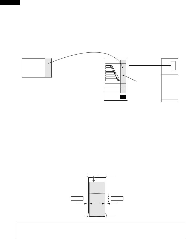
ENERGY LABEL
Usage of "the ENERGY LABEL"
When displaying this refrigerator in the shop-window, attach the "ENERGY LABEL" to it in the following procedure.
Fix the data part of "ENERGY LABEL (DATA)" on the data part of "ENERGY LABEL (BASE)"
"ENERGY LABEL (DATA)"
(This label is in Operation manual)
E
A
B
C
D
E

F
G
Data part
"ENERGY LABEL (BASE)" |
Refrigerator |
|
of each language |
||
|
INSTALLATION
Free standing type
To ensure adequate ventilation for this refrigerator, install with 6 cm space at the rear and both sides, with a minimum space of 9 cm above the refrigerator.
|
9cm |
6cm |
6cm |
 This refrigerator shall be used under the ordinary place condition between +5˚C and +43˚C of ambient temperature, and also not be left under -10˚C for long days.
 To be used this refrigerator within the range of the rated voltage ±6%.
2
SJ-58L-T2
SJ-63L-T2
SJ-68L-T2
CAUTIONS AND INFORMATIONS
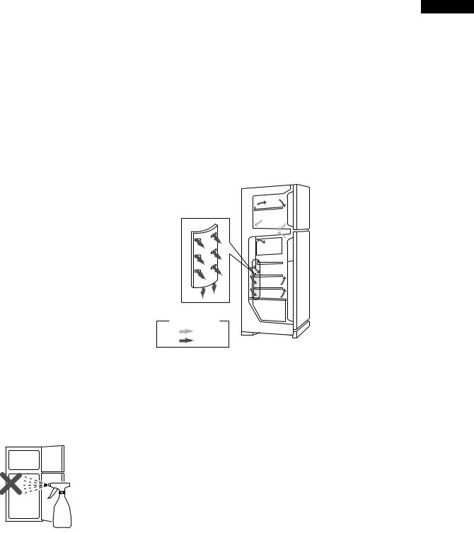
In case of following troubles, the cause is not related with the failure of refrigerator.
Please mention the correct way to the customer for the use of refrigerator when the repairing.
1. Some foods freezed in the refrigerator compartment.
Do not place food directly in front of cold air outlet.
This may lead to the food freezing.
cold air flow
IN OUT
2. Some plastic parts were cracked or splitted.
Some household cleaning chemicals may affect the internal food liner and plastic parts resulting in splitting or cracks occurring.
When cleaning all plastic parts inside this refrigerator, only use diluted dishwashing liquid(soapy water). Make sure that all plastic parts are thoroughly rinsed with water after cleaning.
3.IT IS NORMAL for the refrigerator to produce the following sounds.
Cracking or crunching sound;
Sound produced by expansion and contraction of inner walls and internal parts during cooling.
Squeaking sound;
Sound produced by expansion and contraction of internal parts.
Sound of flowing fluid (gurgling sound, fizzing sound);
Sound of refrigerant flowing in pipes (sound may become louder from time to time).
3
SJ-58L-T2
SJ-63L-T2
SJ-68L-T2
SPECIFICATIONS
Items |
|
|
SJ-58L-T2 |
|
|
|
|
|
|
|
|
SJ-63L-T2 |
SJ-68L-T2 |
|||||
Type |
|
|
2-Door |
|
|
|
|
|
|
|
|
2-Door |
|
2-Door |
|
|||
Outer dimensions |
|
Height |
1620mm(63.8") |
|
1720mm(67.7") |
1820mm(71.6") |
||||||||||||
(Including spacer) |
|
Width |
760mm(29.9") |
|
|
760mm(29.9") |
760mm(29.9") |
|||||||||||
|
|
|
Depth |
740mm(29.1") |
|
|
740mm(29.1") |
740mm(29.1") |
||||||||||
Rated storage volume |
|
|
492 liter |
(17.4 cu.ft) |
|
535 liter |
(18.9 cu.ft) |
577 liter |
(20.4cu.ft) |
|||||||||
|
|
|
|
|
F: 151 liter (5.3 cu.ft) |
|
F: 151 liter (5.3 cu.ft) |
F: 151 liter (5.3 cu.ft) |
||||||||||
|
|
|
|
|
R: 341 liter(12.1 cu.ft) |
|
R: 384 liter(13.6 cu.ft) |
R: 426 liter(15.1 cu.ft) |
||||||||||
Rated gross volume |
|
|
525 liter |
(18.6 cu.ft) |
|
565 liter |
(20.0 cu.ft) |
610 liter |
(21.6 cu.ft) |
|||||||||
|
|
|
|
|
F: 171 liter (6.1cu.ft) |
|
F: 171 liter (6.1cu.ft) |
F: 171 liter (6.1cu.ft) |
||||||||||
|
|
|
|
|
R: 354 liter(12.5cu.ft) |
|
R: 394 liter(13.9cu.ft) |
R: 439 liter(15.5cu.ft) |
||||||||||
Defrosting |
|
System |
Heater system |
|
|
|
|
|
||||||||||
|
|
|
Start |
Automatic |
|
|
|
|
|
|
|
|
|
|
|
|
|
|
|
|
|
Finish |
Automatic |
|
|
|
|
|
|
|
|
|
|
|
|
|
|
Temperature control |
|
|
Automatic (Adjustable) |
|
|
|
|
|
||||||||||
No-frost freezer |
|
|
Yes |
|
|
|
|
|
|
|
|
|
|
|
|
|
||
Interior lamp |
|
|
2 |
|
|
|
|
|
|
|
|
|
|
|
|
|
||
Caster |
|
|
4 |
|
|
|
|
|
|
|
|
|
|
|
|
|
||
Evaporating pan |
|
|
1 |
|
|
|
|
|
|
|
|
|
|
|
|
|
||
Refrigerator |
|
R glass shelf ass'y |
2 |
|
|
|
|
|
|
|
|
|
|
|
3 |
|
||
Compartment |
|
V glass shelf ass'y |
1 |
|
|
|
|
|
|
|
|
|
|
|
|
|
||
|
|
|
Vegetable case |
1 |
|
|
|
|
|
|
|
|
|
|
|
|
|
|
|
|
|
Fruit case |
1 |
|
|
|
|
|
|
|
|
|
|
|
|
|
|
|
|
|
R door pocket |
1 |
|
|
|
|
|
|
|
|
|
|
|
2 |
|
|
|
|
|
Egg tray |
2 |
|
|
|
|
|
|
|
|
|
|
|
|
|
|
|
|
|
Bottle pocket |
2 |
|
|
|
|
|
|
|
|
|
|
|
|
|
|
|
|
|
Utility case pocket |
1 |
|
|
|
|
|
|
|
|
|
|
|
|
|
|
|
|
|
Chilled case |
1 |
|
|
|
|
|
|
|
|
|
|
|
|
|
|
|
|
|
Tube stand |
2 |
|
|
|
|
|
|
|
|
|
|
|
|
|
|
Freezer |
|
Freezer shelf ass'y |
1 |
|
|
|
|
|
|
|
|
|
|
|
|
|
||
Compartment |
|
Ice cube maker |
Twin ice cube maker |
|
|
|
|
|
||||||||||
|
|
|
Ice storage box |
1 |
|
|
|
|
|
|
|
|
|
|
|
|
|
|
|
|
|
F door pocket |
2 |
|
|
|
|
|
|
|
|
|
|
|
|
|
|
Deodorizing system |
|
|
No |
|
|
|
|
|
|
|
|
|
|
|
|
|
||
RATING |
|
|
|
|
|
|
|
|
|
|
|
|
|
|
|
|
||
Items |
|
|
SJ-58L-T2 |
|
|
|
|
|
|
|
|
SJ-63L-T2 |
SJ-68L-T2 |
|||||
Rated voltage |
|
(V~) |
220-240 |
|
|
|
|
|
|
|
|
|
|
|
|
|
||
Rated frequency |
|
(Hz) |
50 |
|
|
|
|
|
|
|
|
|
|
|
|
|
||
Climate class |
|
|
T |
|
|
|
|
|
|
|
|
|
|
|
|
|
||
Rated input |
|
(W) |
170-190 |
|
|
|
|
|
|
|
|
|
|
|
|
|
||
Rated input of heating elements |
(W) |
138-164 |
|
|
|
|
|
|
|
|
|
|
|
|
|
|||
Refrigerant (Charging quantity) |
HFC-134a(120g) |
|
HFC-134a(125g) |
HFC-134a(130g) |
||||||||||||||
Net Weight |
|
(kg) |
81 |
|
|
|
|
|
|
|
|
83 |
|
88 |
|
|||
Plug cord |
|
|
3wires |
|
|
|
|
|
|
|
|
|
|
|
|
|
||
Plug type |
|
|
CS |
|
|
|
|
|
|
|
|
|
|
|
|
|
||
|
|
|
|
|
Hole |
|
|
|
|
|
|
|
|
|
|
|
|
|
|
|
|
|
|
|
|
|
|
|
|
|
|
|
|
|
|
|
|
|
|
|
|
|
|
|
|
|
|
|
|
|
|
|
|
|
|
|
|
|
|
|
|
|
|
|
|
|
|
|
|
|
|
|
|
|
|
|
|
|
|
|
|
|
|
|
|
|
|
|
|
|
|
|
|
|
|
|
|
|
|
|
|
|
|
|
|
|
|
|
|
|
|
|
|
COLOR
Items |
T2G |
T2A |
T2W |
Outside color |
Gray |
Beige |
White |
Inside color |
White |
|
|
OPTIONAL ITEM |
|
|
|
SJ-L838LD (REFRIGERATOR HINGE KITS). For changing the door to left side opening.
4

|
|
|
SJ-58L-T2 |
|
|
|
|
SJ-63L-T2 |
|
|
|
|
SJ-68L-T2 |
|
|
DESIGNATION OF VARIOUS PARTS |
|||
|
|
The names are the denominations used in the |
||
|
|
REPLACEMENT PARTS LIST. |
||
|
|
1. |
Freezer light(Lamp) |
|
1 |
18 |
2. |
Freezer fan |
|
2 |
3. |
Freezer shelf(F shelf ass'y) |
||
19 |
4. |
Ice cube maker |
||
3 |
5. |
Ice cube box(Ice storage box) |
||
|
6. |
Freezer temp. control knob |
||
4 |
20 |
7. |
Chilled case |
|
5 |
21 |
8. |
Refrigerator temp. control knob |
|
9. |
Refrigerator fan |
|||
6 |
22 |
|||
10. |
Refrigerator light(Lamp) |
|||
7 |
||||
|
11. |
Refrigerator shelf(R glass shelf ass'y) |
||
8 |
|
|||
23 |
|
(SJ-58L/ SJ-63L; 2 shelves, SJ-68L; 3 shelves) |
||
9 |
12. |
Shelf(V glass shelf ass'y) |
||
|
||||
10 |
24 |
13. |
Fruit case |
|
11 |
14. |
Vegetable crisper(Vegetable case) |
||
25 |
||||
|
15. |
Evaporating pan & cover |
||
12 |
26 |
16. |
Caster |
|
13 |
|
17. |
Adjustable feet(Adjustable leg ass'y) |
|
14 |
27 |
18. |
Fan & light switch(for freezer) |
|
15 |
19. |
Fan & light switch(for refrigerator) |
||
|
20. |
Freezer pocket(F door pocket) |
||
|
|
|||
16 |
22 |
21. |
Water cup |
|
17 |
22. |
Magnetic door seal(Door packing) |
||
|
23. |
Utility pocket(Utility case pocket) |
||
|
|
24. |
Egg holder(Egg tray) |
|
|
Figure D-1. External Description |
25. |
Free pocket(R door pocket) |
|
|
|
(SJ-58L/63L; 1 pocket, SJ-68L; 2 pockets) |
||
|
|
|
||
|
|
26. |
Bottle pocket |
|
|
|
27. |
Bottle guard(Tube stand) |
|
Upper hinge cover |
Mark: Cold air flow |
Hot pipe |
Freezer fan |
|
Fan motor |
Freezer |
Defrost thermostat |
compartment |
Evaporator |
|
|
Freezer temp. control knob |
Defrost heater |
|
|
Hot pipe |
|
Refrigerator |
Timer, R-fan themo. ass’y |
compartment |
Refrigerator fan |
|
Damper thermostat |
|
Refrigerator temp. control knob |
|
Drain pipe |
Fruit case |
|
|
Vegetable case |
Ventilating grille |
Compressor |
Evaporating pan |
Starting relay, Overload relay(Protector) |
|
|
Adjustable leg ass’y |
Sub. condenser |
|
|
|
Caster |

 This figure shows SJ-63L
Figure D-2. Constructions
5

SJ-58L-T2
SJ-63L-T2
SJ-68L-T2
LIST OF ELECTRICAL PARTS
ITEMS |
|
|
|
|
|
|
|
|
|
|
|
|
TYPE NAME |
|
|
|
|
RATING |
|
|
|
|
|
|
|
|
SPECIFICATIONS |
||||||||||||||||||||||||||||||||||||||||||
Thermostat |
|
MM1-8123 |
125V |
6A |
|
(At normal notch) |
|
|
|
|
|
|
|
|
|
|
|||||||||||||||||||||||||||||||||||||||||||||||||||||
|
|
|
|
|
|
|
|
|
|
|
|
|
|
|
|
|
|
|
|
|
|
|
|
|
250V |
3A |
|
ON/OFF : -19/-24˚C |
|
|
|
|
|
|
|
|
|
|
|||||||||||||||||||||||||||||||
Defrost thermostat |
|
S101 |
250V |
8A |
|
Open/Close : 10/1˚C |
|
|
|
|
|
|
|
|
|
|
|||||||||||||||||||||||||||||||||||||||||||||||||||||
Thermo. fuse |
|
SF70E |
250V |
10A |
|
Working temp. : 70˚C |
|
|
|
|
|
|
|
|
|
|
|||||||||||||||||||||||||||||||||||||||||||||||||||||
F-fan motor |
|
3R00044B |
220-240V 50/60Hz |
|
Working with ø100 fan |
|
|
|
|
|
|
|
|
|
|
||||||||||||||||||||||||||||||||||||||||||||||||||||||
R-fan motor |
|
|
|
|
|
|
|
|
3R00122A |
220-240V 50/60Hz |
|
Working with ø80 fan |
|
|
|
|
|
|
|
|
|
|
|||||||||||||||||||||||||||||||||||||||||||||||
|
|
|
|
|
|
|
|
|
|
|
|
|
|
|
|
|
|
|
|
|
|
|
|
|
|
|
|
|
|
|
|
|
|
|
|
|
|
|
|
|
|
|
|
|
|
|
|
|
|
|
|
|
|
|
|
|
|
|
|
|
|
|
|
|
|
|
|
|
|
|
|
(R-fan fuse) |
123 |
|
|
|
|
|
|
|
|
|
|
|
250V |
2A |
|
Cut OFF 130˚C |
|
|
|
|
|
|
|
|
|
|
|||||||||||||||||||||||||||||||||||||||||
Defrost heater |
|
MM6-4198 |
220-240V 353Ω |
|
150W at 230V |
|
|
|
|
|
|
|
|
|
|
||||||||||||||||||||||||||||||||||||||||||||||||||||||
Door switch |
|
DSD-5 |
250V |
0.25A |
|
4 terminals push-button type |
|||||||||||||||||||||||||||||||||||||||||||||||||||||||||||||||
Damper thermostat |
|
MM1-6170(SJ-63L/68L) |
— |
|
|
|
|
|
|
|
|
|
|
|
Open/Close : 3/-2˚C |
|
|
|
|
|
|
|
|
|
|
||||||||||||||||||||||||||||||||||||||||||||
|
|
|
|
|
|
|
|
|
|
MM1-6171(SJ-58L) |
— |
|
|
|
|
|
|
|
|
|
|
|
Open/Close : 5/0˚C |
|
|
|
|
|
|
|
|
|
|
||||||||||||||||||||||||||||||||||||
Defrost timer |
|
TMDF904FD2 |
220-240V |
|
Integration type |
|
|
|
|
|
|
|
|
|
|
||||||||||||||||||||||||||||||||||||||||||||||||||||||
|
|
|
|
|
|
|
|
|
|
|
|
|
|
|
|
|
|
|
|
|
|
|
|
|
50/60Hz |
|
Cycle time : 10.8/9.0 hours(50/60Hz) |
||||||||||||||||||||||||||||||||||||||||||
|
|
|
|
|
|
|
|
|
|
|
|
|
|
|
|
|
|
|
|
|
|
|
|
|
|
|
|
|
|
|
|
|
|
|
|
|
|
|
|
|
Delay time : 4.3/3.6 min.(50/60Hz) |
||||||||||||||||||||||||||||
Lamp socket (F/R) |
|
— |
250V |
1A |
|
E-12(Hard plastic body type) |
|||||||||||||||||||||||||||||||||||||||||||||||||||||||||||||||
|
|
|
|
|
|
|
|
|
|
|
|
|
|
|
|
|
|
|
|
|
|
|
|
|
|||||||||||||||||||||||||||||||||||||||||||||
F-lamp |
|
|
|
|
|
|
|
|
|
— |
240V |
10W |
|
E-12 |
|
|
|
|
|
|
|
|
|
|
|||||||||||||||||||||||||||||||||||||||||||||
R-lamp |
|
|
|
|
|
|
|
|
|
— |
240V |
15W |
|
E-12 |
|
|
|
|
|
|
|
|
|
|
|||||||||||||||||||||||||||||||||||||||||||||
R-fan thermo. |
R-fan thermo. |
|
S101 |
250V |
8A |
|
Open/ Close : 7/15˚C |
|
|
|
|
|
|
|
|
|
|
||||||||||||||||||||||||||||||||||||||||||||||||||||
ass'y |
R-fan thermo.heater |
|
RSS2 |
350V, |
2W, 10kΩ |
|
1.1W at 230V |
|
|
|
|
|
|
|
|
|
|
||||||||||||||||||||||||||||||||||||||||||||||||||||
SJ-58L,63L |
|
|
|
|
|
|
|
|
|
|
|
|
|
|
|
|
|
|
|
|
|
|
|
|
|
|
|
|
|
|
|
|
|
|
|
|
|
|
|
|
|
|
|
|
|
|
|
|
|
|
|
|
|
|
|
|
|
|
|
|
|
||||||||
Compressor |
|
GLY80AA |
220-240V/50Hz |
|
Cooling capacity : 197kcal/h(50Hz) |
||||||||||||||||||||||||||||||||||||||||||||||||||||||||||||||||
|
|
|
|
|
|
|
|
|
|
|
|
|
|
|
|
|
|
|
|
|
|
|
|
|
|
|
|
|
|
|
|
|
|
|
|
|
|
|
|
|
Main coil : 10.3Ω |
Common |
|||||||||||||||||||||||||||
|
|
|
|
|
|
|
|
|
|
|
|
|
|
|
|
|
|
|
|
|
|
|
|
|
|
|
|
|
|
|
|
|
|
|
|
|
|
|
|
|
Aux. coil : 14.2Ω |
|
|
|
|
|
|
|
|
|
|
||||||||||||||||||
|
|
|
|
|
|
|
|
|
|
|
|
|
|
|
|
|
|
|
|
|
|
|
|
|
|
|
|
|
|
|
|
|
|
|
|
|
|
|
|
|
|
|
|
|
|
|
|
|
|
||||||||||||||||||||
|
|
|
|
|
|
|
|
|
|
|
|
|
|
|
|
|
|
|
|
|
|
|
|
|
|
|
|
|
|
|
|
|
|
|
|
|
|
|
|
|
(at 25˚C) |
|
|
|
|
|
|
|
|
|
|
||||||||||||||||||
|
|
|
|
|
|
|
|
|
|
|
|
|
|
|
|
|
|
|
|
|
|
|
|
|
|
|
|
|
|
|
|
|
|
|
|
|
|
|
|
|
|
|
|
|
|
|
|
|
|
||||||||||||||||||||
|
|
|
|
|
|
|
|
|
|
|
|
|
|
|
|
|
|
|
|
|
|
|
|
|
|
|
|
|
|
|
|
|
|
|
|
|
|
|
|
|
|
|
|
|
|
|
|
|
|
|
|
|
|
|
Aux. coil |
|
|
|
|
|
Main coil |
||||||||
|
|
|
|
|
|
|
|
|
|
|
|
|
|
|
|
|
|
|
|
|
|
|
|
|
|
||||||||||||||||||||||||||||||||||||||||||||
Starting relay |
|
UH3003-7 |
— |
|
|
|
|
|
|
|
|
|
|
|
14.0 Ω + 30% |
|
|
|
|
|
|
|
|
|
|
||||||||||||||||||||||||||||||||||||||||||||
Runnig capacitor |
|
— |
430VAC 5μF |
|
— |
|
|
|
|
|
|
|
|
|
|
||||||||||||||||||||||||||||||||||||||||||||||||||||||
|
|
|
|
|
|
|
|
|
|
|
|
|
|
|
|
|
|
|
|
|
|
|
|
|
|
||||||||||||||||||||||||||||||||||||||||||||
Overload relay(Protector) |
|
4TM308NFBYY |
— |
|
|
|
|
|
|
|
|
|
|
|
Open/ Close : 120/61˚C |
|
|
|
|
|
|
|
|
|
|
||||||||||||||||||||||||||||||||||||||||||||
SJ-68L |
|
|
|
|
|
|
|
|
|
|
|
|
|
|
|
|
|
|
|
|
|
|
|
|
|
|
|
|
|
|
|
|
|
|
|
|
|
|
|
|
|
|
|
|
|
|
|
|
|
|
|
|
|
|
|
|
|
|
|
|
|
|
|
|
|
|
|
|
|
Compressor |
|
GLY90AA |
220-240V/50Hz |
|
Cooling capacity : 220kcal/h(50Hz) |
||||||||||||||||||||||||||||||||||||||||||||||||||||||||||||||||
|
|
|
|
|
|
|
|
|
|
|
|
|
|
|
|
|
|
|
|
|
|
|
|
|
|
|
|
|
|
|
|
|
|
|
|
|
|
|
|
|
Main coil : 8.8Ω |
Common |
|||||||||||||||||||||||||||
|
|
|
|
|
|
|
|
|
|
|
|
|
|
|
|
|
|
|
|
|
|
|
|
|
|
|
|
|
|
|
|
|
|
|
|
|
|
|
|
|
Aux. coil : 14.2Ω |
|
|
|
|
|
|
|
|
|
|
||||||||||||||||||
|
|
|
|
|
|
|
|
|
|
|
|
|
|
|
|
|
|
|
|
|
|
|
|
|
|
|
|
|
|
|
|
|
|
|
|
|
|
|
|
|
|
|
|
|
|
|
|
|
|
||||||||||||||||||||
|
|
|
|
|
|
|
|
|
|
|
|
|
|
|
|
|
|
|
|
|
|
|
|
|
|
|
|
|
|
|
|
|
|
|
|
|
|
|
|
|
(at 25˚C) |
|
|
|
|
|
|
|
|
|
|
||||||||||||||||||
|
|
|
|
|
|
|
|
|
|
|
|
|
|
|
|
|
|
|
|
|
|
|
|
|
|
|
|
|
|
|
|
|
|
|
|
|
|
|
|
|
|
|
|
|
|
|
|
|
|
||||||||||||||||||||
|
|
|
|
|
|
|
|
|
|
|
|
|
|
|
|
|
|
|
|
|
|
|
|
|
|
|
|
|
|
|
|
|
|
|
|
|
|
|
|
|
|
|
|
|
|
|
|
|
|
|
|
|
|
|
Aux. coil |
|
|
|
|
|
Main coil |
||||||||
|
|
|
|
|
|
|
|
|
|
|
|
|
|
|
|
|
|
|
|
|
|
|
|
|
|
||||||||||||||||||||||||||||||||||||||||||||
Starting relay |
|
UH3003-7 |
— |
|
|
|
|
|
|
|
|
|
|
|
14.0 Ω + 30% |
|
|
|
|
|
|
|
|
|
|
||||||||||||||||||||||||||||||||||||||||||||
Runnig capacitor |
|
— |
430VAC 5μF |
|
|
|
|
|
|
|
|
|
|
|
|
|
|
|
|
|
|
|
|
|
|
|
|
|
|
|
|
|
|
||||||||||||||||||||||||||||||||||||
Overload relay(Protector) |
|
4TM757NFBYY |
— |
|
|
|
|
|
|
|
|
|
|
|
Open/ Close : 120/61˚C |
|
|
|
|
|
|
|
|
|
|
||||||||||||||||||||||||||||||||||||||||||||
|
|
|
|
|
|
|
|
|
|
|
|
|
|
|
|
|
|
|
|
|
|
|
|
|
|
|
|
|
|
|
|
|
|
|
|
|
|
|
|
|
|
|
|
|
|
|
|
|
|
|
|
|
|
|
|
|
|
|
|
|
|
|
|
|
|
|
|
|
|
6
SJ-58L-T2
SJ-63L-T2
SJ-68L-T2
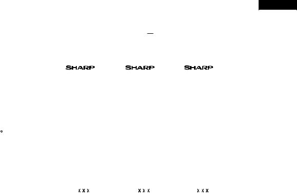
THE FICHE (according to ANNEX  : 94/2/EC)
NO. |
Items |
|
|
|
|
|
|
Description |
|
|
|
|
|
Remarks |
||||
1 |
Trade mark |
|
|
|
|
|
|
|
|
|
|
|
|
|
|
|
|
|
2 |
Model name |
|
SJ-58L-T2 |
SJ-63L-T2 |
SJ-68L-T2 |
|
||||||||||||
3 |
Type |
|
Category; 7 |
Category; 7 |
Category; 7 |
|
||||||||||||
|
|
|
Refrigerator/Freezer |
Refrigerator/Freezer |
Refrigerator/Freezer |
|
||||||||||||
|
|
|
|
|
|
|
|
|
|
|
|
|
|
|
|
|
|
|
4 |
Energy efficiency class |
|
|
|
B |
|
|
B |
|
|
B |
|
||||||
5 |
Eco-award mark |
|
|
|
|
|
|
|
|
|
|
|
|
|
|
|
|
880/92 |
|
|
|
|
|
|
|
|
|
|
|
|
|
|
|
|
|||
6 |
Energy consumption |
|
675 |
|
|
705 |
|
|
734 |
|
|
EN153 |
||||||
|
(220V 50Hz at 25 C) |
|
kWh/year |
kWh/year |
kWh/year |
|
||||||||||||
|
|
|
|
|
|
|
|
|
|
|
|
|
|
|
|
|
|
|
7 |
Net storage volume of fresh |
|
|
|
341 L |
|
|
384 L |
|
|
426 L |
|
||||||
|
food storage compartment |
|
|
|
|
|
|
|
|
|
|
|
|
|
|
|
|
|
|
|
|
|
|
|
|
|
|
|
|
|
|
|
|
|
|
|
|
8 |
Net storage volume of fresh |
|
|
|
151 L |
|
|
151 L |
|
|
151 L |
|
||||||
|
frozen food storage compartment |
|
|
|
|
|
|
|
|
|
|
|
|
|
|
|
|
|
|
|
|
|
|
|
|
|
|
|
|
|
|
|
|
|
|
|
|
9 |
Star rating of frozen food |
|
|
4-STAR |
|
4-STAR |
|
4-STAR |
|
|||||||||
|
compartment |
|
|
|
|
|
|
|
|
|
|
|
|
|
|
|
|
|
|
|
|
|
|
|
|
|
|
|
|
|
|
|
|
|
|
|
|
10 |
No frost |
|
No frost |
|
No frost |
|
No frost |
|
||||||||||
11 |
Temperature rise time |
|
|
|
10 h |
|
|
10 h |
|
|
10 h |
|
||||||
12 |
Freezing capacity |
|
8 kg /24h |
8 kg /24h |
8 kg /24h |
|
||||||||||||
13 |
Climate class |
|
|
|
T |
|
|
T |
|
|
T |
|
||||||
14 |
Noise |
|
41 dB(A) |
41 dB(A) |
|
41 dB(A) |
86/594/EEC |
|||||||||||
|
|
|
re 1 pw |
re 1 pw |
|
re 1 pw |
dB(A) re 1 pw |
|||||||||||
|
|
(96/57/EC) |
|
|
|
|
|
|
|
|
|
|
|
|||||
|
|
|
|
|
|
|
|
|
|
|
|
|
|
|
|
|
|
|
15 |
Maximum allowable electricity |
|
942 |
|
|
989 |
|
|
1033 |
|
|
|
||||||
|
consumption (Emax) |
|
kWh/year |
kWh/year |
kWh/year |
|
||||||||||||
|
|
|
|
|
|
|
|
|
|
|
|
|
|
|
|
|
|
|
7
SJ-58L-T2
SJ-63L-T2
SJ-68L-T2
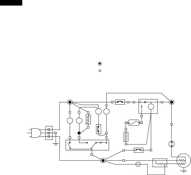
WIRING DIAGRAM
Be sure to replace the electrical parts with specified ones for maintaining the safety and performance of the set.
G |
: GRAY |
|
Br |
: BROWN |
|
O |
: ORANGE |
|
Y |
: YELLOW |
|
R |
: RED |
CONNECTED IN TERMINAL BOX |
P |
: PINK |
|
B |
: BLUE |
CONNECTOR |
Bk |
: BLACK |
|
S-B |
: SKY-BLUE |
|
G-Y : GREEN-YELLOW |
|
|
W |
: WHITE |
|
|
(BR) |
|
F-THERMOSTAT |
|
|
|
(G) |
|
|
|
|
|
|
|
|
|
|
|
|
|
|
(R) |
3 |
|
|
4 |
|
|
|
|
|
|
TM |
||
|
|
R |
F |
|
|
|
DEFROST |
|
|
|
|
|
|
|
|||
|
|
FM |
FM |
|
|
|
|
TIMER |
|
|
|
|
|
|
|
||
F |
R |
R-FAN THERMO. |
THERMO. |
2 |
1 |
|
||
|
|
FUSE |
|
|
|
|
||
L |
L |
HEATER |
|
|
|
|
|
|
|
|
|
(W) |
|
|
(BK) |
|
|
|
(S-B) |
R-FAN |
(O) |
DEFROST |
|
|
|
|
|
|
|
|
|
||||
2 |
4 |
THERMO. |
3 |
HEATER |
|
|
PROTECTOR |
|
|
|
|
|
|
|
|
|
|
SOURCE CORD |
|
|
|
|
|
(Y) |
|
|
|
|
|
|
|
|
|
|
|
DOOR SWITCH |
1 |
|
|
DEFROST |
|
COMPRESSOR |
||
|
|
|
|
|
|
C |
||
|
|
|
|
|
THERMOSTAT |
|||
|
|
|
|
|
|
|||
|
|
|
|
|
|
|
|
M |
|
|
(B) |
|
|
|
|
A |
|
|
|
|
|
|
|
|
||
RUNNING |
STARTING |
CAPACITOR |
RELAY |
Figure W-1. Wiring Diagram
8
SJ-58L-T2
SJ-63L-T2
SJ-68L-T2
F LAMP BOX ASS’Y |
|
|
|
|
|
|
|
|
|
|
|
|
|
|
|
|
|
|
|
|
|
|
|
|
CABINET ASS’Y |
|
||||||||||
|
|
|
|
|
|
|
|
|
|
|
|
|
|
|
|
|
|
|
|
|
|
|
|
|
|
|
|
|
|
|
|
|
|
|
|
|
|
|
|
|
|
|
|
|
|
LAMP SOCKET |
|
|
|
BR-1 |
|
|
|
|
|
|
|
|
|
|
|
|
|
||||||||||
F-LAMP(10W) |
L |
|
|
|
|
|
|
|
|
|
|
|
|
|
|
|
|
1 |
|
1 |
W-2 |
|
|
|
|
|
|
|
|
|
|
|
|
|
||
|
|
|
|
|
|
|
|
|
|
|
|
|
|
|
|
2 |
|
2 |
|
|
|
|
|
|
|
|
|
|
|
|
|
|||||
|
|
|
|
|
|
|
|
|
|
|
|
|
|
|
|
|
|
|
|
|
|
|
|
|
|
|
|
|
|
|
||||||
E. V. COVER ASS’Y |
|
|
|
|
|
|
|
|
|
|
|
|
|
|
|
|
|
|
|
|
|
|
|
|
|
|
|
|
|
|
|
|
|
|
||
|
|
|
|
|
|
|
|
|
|
|
|
|
|
|
|
|
|
|
|
|
|
|
|
|
|
|
|
|
|
|
|
|
|
|
|
|
|
|
|
|
|
|
LEAD EV-COVER ASS’Y |
|
|
|
GY-1 |
|
|
|
|
|
|
|
|
|
|
|
|
|
|||||||||||||
F-FAN MOTOR FM |
|
|
|
|
|
|
|
|
|
|
|
|
|
|
1 |
|
1 |
OR-1 |
|
|
|
|
|
|
|
|
|
|
|
|
|
|||||
|
|
|
|
|
|
|
|
|
|
|
|
|
2 |
|
2 |
|
|
|
|
|
|
|
|
|
|
|
|
|
||||||||
|
|
|
|
|
|
|
|
|
|
|
|
|
|
|
|
|
|
|
|
3 |
|
3 |
R-1 |
|
|
|
|
|
|
|
|
|
|
|
|
|
F-THERMOSTAT |
|
|
|
|
|
|
|
|
|
|
|
|
|
|
|
|
|
|
|
4 |
|
4 |
BR-2 |
|
|
|
|
|
|
|
|
|
|
|
|
|
|
|
|
|
|
|
|
|
|
|
|
|
|
|
|
|
|
|
|
|
|
|
|
|
|
|
|
|
|
|
|
|
|
||||
|
|
|
|
|
|
|
|
|
|
|
|
|
|
|
|
|
|
|
|
Y-1 |
|
|
|
|
|
|
|
|
|
|
|
|
|
|||
|
|
|
|
|
|
|
|
|
|
|
|
|
|
|
|
|
|
|
|
|
|
|
|
|
|
|
|
|
|
|
|
|
|
|
|
|
DEF. THERMO. ASS’Y |
|
|
|
|
|
|
|
|
|
|
|
|
|
|
|
|
5 |
|
5 |
BL-1 |
|
|
|
|
|
|
|
|
|
|
|
|
|
|||
|
|
|
|
|
|
|
|
|
6 |
|
6 |
|
|
|
|
|
|
|
|
|
|
|
|
|
||||||||||||
|
|
|
|
|
|
|
|
|
|
|
|
|
|
|
|
|
|
|
|
|
BK-1 |
|
|
|
|
|
|
|
|
|
|
|
|
|
||
FUSE ASS’Y |
|
|
|
|
|
|
|
|
|
|
|
|
|
|
|
|
|
|
|
7 |
|
7 |
W-1 |
|
|
|
|
|
|
|
|
|
|
|
|
|
|
|
|
|
|
|
|
|
|
|
|
|
|
|
|
|
|
|
|
8 |
|
8 |
|
|
|
|
|
|
|
|
|
|
|
|
|
||
|
|
|
|
|
|
|
|
|
|
|
|
|
|
|
|
|
|
|
|
9 |
|
9 |
OR-3 |
|
|
|
|
|
|
|
|
|
|
|
|
|
|
|
|
|
|
|
|
|
|
|
|
|
|
|
|
|
|
|
|
|
|
(W-1) |
|
|
|
|
|
|
|
|
|
|
|
|
|
||
|
|
|
|
|
|
|
|
|
|
|
|
|
|
|
|
|
|
|
|
|
|
|
|
|
|
|
|
|
|
|
|
|
|
|
|
|
DEF. HEATER ASS’Y |
|
|
|
|
|
|
|
|
|
|
|
|
|
|
|
|
|
|
1 |
|
1 |
Y-2 |
|
|
|
|
|
|
|
|
|
|
|
|
|
|
|
|
|
|
|
|
|
|
|
|
|
|
|
2 |
|
2 |
|
|
|
|
|
|
|
|
|
|
|
|
|
||||||||
|
|
|
|
|
|
|
|
|
|
|
|
|
|
|
|
|
|
|
|
|
|
|
|
|
|
|
|
|
|
|
|
|
|
|
||
DOOR SWITCH |
|
|
|
|
3 (PUSH CLOSE) |
|
3 |
(OR-1) |
|
|
BL-2 |
|||
1 (NEUTRAL) |
|
1 |
||
|
SB-1 |
|||
4 (PUSH OPEN) |
|
4 |
||
|
(W-2) |
|||
2 (PUSH OPEN) |
|
2 |
||
|
|
|||
R CONTROL COV. ASS’Y |
|
|
|
|
|
3 |
3 |
|
(R-1) |
|
|
(BK-1) |
||
|
2 |
2 |
|
|
|
|
GY-2 |
||
|
4 |
4 |
|
|
|
|
(Y-1) |
||
TM |
1 |
1 |
|
|
|
(Y-2) |
|||
|
|
|
|
|
DEFROST TIMER |
|
|
|
|
(R-FAN |
|
|
|
|
|
|
|
|
|
|
|
SB-2 |
|
||
THERMO. HEATER) |
|
|
|
|
|
|
|
|
1 |
|
1 |
BR-3 |
|
||
|
|
|
|
|
2 |
|
2 |
|
|||||||
|
|
|
|
|
|
|
|
|
OR-3 |
|
|
|
|||
R FAN THERMO. |
|
|
|
|
|
|
|
|
3 |
|
3 |
|
|
||
|
|
|
|
|
|
|
|
|
|
|
|||||
|
|
|
|
|
OR-2 |
|
|
||||||||
4 |
|
4 |
|
|
|||||||||||
|
|
|
|
|
|
|
|
|
|
|
|
||||
|
|
|
|
|
|
|
|
|
|
|
|
||||
|
|
|
|
|
|
|
|
|
|
|
|
|
|
||
R LAMP BOX ASS’Y |
|
|
|
|
|
R-FAN MOTOR |
FM |
1 |
1 |
BR-4 |
|
2 |
2 |
(OR-2) |
|||
|
|||||
R-LAMP (15W) |
L |
3 |
3 |
SB-3 |
|
4 |
4 |
|
|||
|
|
|
|||
|
|
LAMP SOCKET |
|
|
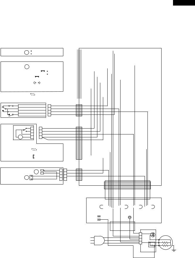
TERMINAL BOX
|
|
BROWN |
|
|
|
BLUE |
GRAY |
|||||||||||||||
|
|
|
|
|
|
|
|
|
|
|
|
|
|
|
|
|
|
|
|
|
|
|
|
|
|
|
|
|
|
|
|
|
|
|
|
|
|
|
|
|
|
|
|
|
|
|
|
|
|
|
|
|
|
|
|
|
|
|
|
|
|
|
|
|
|
|
|
|
RUNNING CAPACITOR |
|
|
|
|
|
EARTH |
|
|
|
|
SKY-BLUE |
|||||||||||
|
|
|
|
|
|
|
|
|
|
|
|
|
||||||||||
|
|
|
|
|
|
|
|
|
|
|
|
|
|
|
|
|
|
|
|
|
|
|
|
|
|
|
|
|
|
|
|
|
|
|
|
|
|
|
|
|
|
|
|
|
|
|
PROTECTOR |
|
1 |
COMPRESSOR |
|
L |
C |
|
E |
||
M |
||
N |
||
A |
||
|
||
SOURCE CORD |
STARTING |
|
|
RELAY |
|
TERMINAL COVER |
||
Figure W-2. Electric Accessories Layout
9
SJ-58L-T2
SJ-63L-T2
SJ-68L-T2
FUNCTIONS
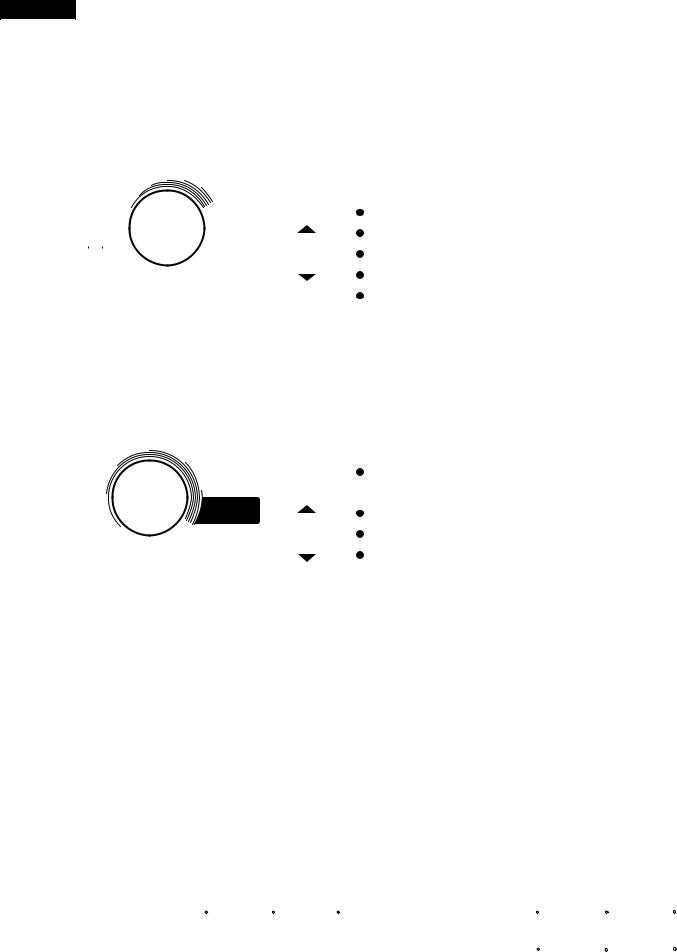
1.ADJUSTABLE TEMPERATURE CONTROL
(1)Temperature control of freezer
 Thermostat (senses freezer temperature) operates on ON/OFF switchover to control the compressor and cool air circulating fan (F-fan motor) , and allows the freezer temperature to keep at a suitable temperature.
  However adjust the freezer temp. control knob as follows depending upon the storing condition of foods.
|
|
MED |
|
|
KNOB |
PURPOSE |
||||||
3 |
4 |
|
5 |
6 |
||||||||
|
|
|
|
|
SETTING |
|
||||||
2 |
|
|
|
|
|
7 |
|
|||||
|
|
|
|
|
|
|||||||
1 |
|
|
|
|
|
|
|
|
|
|||
|
|
|
|
|
MAX(Coldest) |
For making ice rapidly or fast freezing. |
||||||
|
MIN |
|
|
|
|
|
MAX |
|||||
|
|
|
|
|
|
|
Coldest |
|
|
|
|
|
|
|
|
|
|
|
|
|
|
|
When restocking with fresh food. |
||
|
|
|
|
|
|
|
|
|
|
|
||
|
|
|
|
|
|
|
|
|
|
|||
|
|
|
|
|
|
|
|
MED |
For normal freezing. |
|||
|
|
|
|
|
|
|
|
|||||
|
|
|
|
|
|
|
|
|||||
|
|
|
|
|
|
|
|
|
|
|
For storing frozen food for a short period (up to one month). |
|
|
|
|
|
|
|
|
|
|
|
|
||
FREEZER TEMP. CONTROL |
|
|
|
|||||||||
|
|
|
|
|||||||||
MIN |
When frozen food or ice cream is not stored. |
|||||||||||
|
Figure F-1. |
|||||||||||
|
|
|
|
|
||||||||
(2) Temperature control of refrigerator
 Damper-thermostat senses temperature of the refrigerator and changes the opening angle of the damper automatically.
However, as the Damper-thermostat has no function to switch on or off the compressor and F-fan motor, the freezer temperature control causes temperature in the refrigerator to vary to some extent.
 However, adjust the refrigerator temp. control knob as follows depending upon the cooling condition.
|
|
MED |
KNOB |
PURPOSE |
|||||
|
|
4 |
|
SETTING |
|
||||
3 |
|
|
|
5 |
|
||||
|
|
|
|
|
|
|
|||
|
|
|
|
CHILLED |
For keeping freshness of food longer. |
||||
|
|
|
|
|
|
||||
2 |
|
|
|
6 |
ZONE |
|
|||
|
|
|
(Coldest) |
|
|||||
|
|
|
|
|
CHILLED |
|
|
|
|
|
|
|
|
|
|
|
|
When the refrigerator does not provide sufficient cooling. |
|
|
MIN 1 |
|
|
|
ZONE |
|
|
|
|
|
|
|
|
|
|
|
|||
|
|
|
|
|
|
|
|||
|
|
|
|
7 Coldest |
MED |
For normal operation. |
|||
|
|
|
|
||||||
|
|
|
|||||||
REFRIGERATOR TEMP. CONTROL |
|
|
|
When the refrigerator provides excessive cooling. |
|||||
|
|
|
|||||||
|
|
|
|||||||
|
|
|
|
|
|
|
|
||
|
|
Figure F-2. |
MIN |
|
|||||
|
|
|
|
|
|
||||
 When the temperature of the refrigerator is higher, R-fan thermo. senses the temperature and the refrigerator is cooled efficiently by running of R-fan motor.
R-fan thermo. heater energizes when the door is opened intend to promote to running of R-fan motor.
NOTE:  The refrigerator temperature is affected also by the freezer temperature. If the freezer temp. control knob is set at the position "MAX", the temperature tends to be lower than the following values, and if set at near the position "MIN", temperature tends to be higher.
 If the refrigerator is operated for a long time with the freezer temperature control sets the "MAX" position, foods stored in the refrigerator compartment may also freeze.
 When refrigerator temperature control sets to the "CHILLED ZONE", some foods stored may freeze.
In this case adjust control set back to the "MED" position.
 When refrigerator temperature control sets to the "CHILLED ZONE", some foods stored in chilled case may also become frozen.
(3) Reference value of temperature
SETTING OF |
MAX |
MED |
MIN |
FREEZER TEMP. |
|||
CONTROL KNOB |
(Coldest) |
|
|
Freezer |
Approx. |
Approx. |
Approx. |
temperature |
-21 C |
-18 C |
-15 C |
|
|
|
|
SETTING OF |
CHILLED |
|
|
REFRIGERATOR TEMP. |
ZONE |
MED |
MIN |
CONTROL KNOB |
(Coldest) |
|
|
Refrigerator |
Approx. |
Approx. |
Approx. |
temperature |
0 C |
3 C |
6 C |
|
|
|
|
Chilled room |
Approx. |
Approx. |
Approx. |
temperature |
-3 C |
1 C |
4 C |
|
|
|
|
The values shown above refer to the case where the freezer temp. control knob is set at "MED".
The values shown above refer to the measurement carried out center area and 1/3 of overall height from the bottom at each of the refrigerator and the freezer after machine has been operated at an ambient temperature of 30˚C with no food stored and the door closed until the temperature is stabilized.
The values vary depending upon frequency of opening and closing the door, ambient temperature, amount of stored foods and manner of storing foods.
10
SJ-58L-T2
SJ-63L-T2
SJ-68L-T2
2. DEFROSTING |
|
(1) No defrosting operation is necessary |
(2) Where is melted frost brought |
No defrosting operation is necessary.
As this machine is so designed that a built-in evaporator cools air and a fan circulates cooled air, neither the freezer nor the refrigerator is frosted, though the evaporator is frosted.
The frosted evaporator is defrosted automatically due to the function of defrosting timer and heater, requiring no defrosting operation.
1.Melted frost is brought into the evaporating pan at the bottom of the set and is evaporated here by the heat of sub condenser.
2.Be sure that the evaporating pan is inserted correctly and is level.
(3)The following circuit diagrams in the table show automatic defrosting function of the refrigerator with timer and defrost thermostat.
Operation |
Electric diagram |
|
|
|
Description |
|
1. Cooling |
Defrost thermostat ON |
Compressor running |
|
The integration timer integrates running |
||
(Normal) |
|
Timer motor running |
|
time of the compressor. When it reaches |
||
|
Thermostat |
Timer contact |
|
|
cycle time of defrost timer, the timer |
|
UOSR C E |
|
|
|
remiTm o t o r |
r |
contact is changed to start defrosting. |
Defrost |
|
|
moCp r e s s o |
|
||
|
Thermo. fuse |
|
|
|
|
|
|
Defrost heater |
TM |
COMP |
|
|
|
|
thermostat (ON) |
|
|
|
|
|
|
Figure F-3. |
|
|
|
|
|
2. Defrosting |
Defrost thermostat ON |
Compressor stops |
|
The timer contact is changed to start |
||
(Time 20 to 30 min.) |
|
Timer motor stops |
|
defrosting, the timer motor stops, and |
||
|
Thermostat |
Timer contact |
|
|
power is supplied to the defrost heater. |
|
RUOSC E |
Defrost |
|
|
remiTm o t o r |
r |
It takes about 20 to 30 min. to defrost. |
|
|
pmoCr e s s o |
When little frosted, the defrosting takes |
|||
|
Thermo. fuse |
|
|
|
||
|
Defrost heater |
TM |
COMP |
|
little time. When much frosted, the def- |
|
|
|
|
|
rosting takes much time. |
||
|
|
|
|
|
|
|
|
thermostat (ON) |
|
|
|
|
|
|
Figure F-4 . |
|
|
|
|
|
3. Drain |
Defrost thermostat OFF |
Compressor stops |
|
When the defrost thermostat becomes |
||
(Time approx. 5 min.) |
|
Timer motor running |
|
OFF, the timer motor starts running. |
||
|
Thermostat |
Timer contact |
|
|
During the operation time (delay time |
|
|
|
|
|
remiTm o t o r |
r |
of defrost time) defrosted water is |
UOSR C E |
Defrost |
|
|
moCp r e s so |
drained outside the refrigerator. |
|
|
Thermo. fuse |
|
|
|
||
|
Defrost heater |
TM |
COMP |
|
|
|
|
thermostat (OFF) |
|
|
|
|
|
|
Figure F-5. |
|
|
|
|
|
4. Restart |
Defrost thermostat OFF |
Compressor running |
|
Timer contact is changed to cooling |
||
(Time approx. 5 min.) |
|
Timer motor stops |
|
operation and the compressor starts |
||
|
Thermostat |
Timer contact |
|
|
running and the timer motor stops. |
|
|
|
|
|
remiTm o t o r |
r |
Defrost thermostat contact becomes ON |
RUOSC E |
Defrost |
|
|
pmoCr e s so |
when it’s cooled. And the timer motor |
|
|
Thermo. fuse |
|
|
|
||
|
Defrost heater |
TM |
COMP |
|
starts running. (Figure F-3.) |
|
|
thermostat (OFF) |
|
|
|
|
|
|
Figure F-6. |
|
|
|
|
|
11
 Loading...