

Drive Technology \ Drive Automation \ System Integration \ Services
Addendum to the
Operating Instructions
MOVIPRO
®
Accessories
Edition 08/2011 19300026 / EN

SEW-EURODRIVE—Driving the world

Contents
Contents
1 General Information ............................................................................................ 4
1.1 Use of this documentation .......................................................................... 4
1.2 Structure of the safety notes ....................................................................... 4
1.3 Rights to claim under limited warranty ........................................................ 5
1.4 Exclusion of liability..................................................................................... 5
1.5 Other applicable documentation ................................................................. 5
1.6 Copyright..................................................................................................... 5
2 PZM2xA-A...-...-00 Power Interface .................................................................... 6
2.1 Type designation......................................................................................... 6
2.2 Nameplate................................................................................................... 6
2.3 Power interface assignment ....................................................................... 7
2.4 Basic unit .................................................................................................... 7
2.5 Scope of functions ...................................................................................... 8
2.6 Maintenance switch .................................................................................... 8
2.7 Power interface – mechanical installation ................................................... 9
2.8 Power interface – electrical installation ..................................................... 11
2.9 Power interfaces – technical data ............................................................. 16
3 Sensor/Actuator Box ........................................................................................ 18
3.1 Sensor/actuator box – electrical installation.............................................. 19
3.2 Technical data of the sensor/actuator box ................................................ 20
4 BW..-0..-0. External Braking Resistors ............................................................ 23
4.1 Braking resistors – mechanical installation ............................................... 24
4.2 Technical data of the external braking resistors ....................................... 28
5 Jumper Plug ...................................................................................................... 33
6 Mounting Accessories...................................................................................... 34
6.1 Handles..................................................................................................... 34
6.2 Mounting brackets..................................................................................... 35
7 Fan Subassembly.............................................................................................. 38
7.1 Mechanische installation of fan subassembly ........................................... 39
Index................................................................................................................... 40
Addendum to the Operating Instructions – MOVIPRO®
3
1
General Information
Use of this documentation
1 General Information
1.1 Use of this documentation
The documentation is an integral part of the product and contains important information
on operation and service. The documentation is written for all employees who assemble,
install, startup, and service this product.
The documentation must be accessible and legible. Make sure that persons responsible
for the system and its operation, as well as persons who work independently on the unit,
have read through the documentation carefully and understood it. If you are unclear
about any of the information in this documentation, or if you require further information,
contact SEW-EURODRIVE.
1.2 Structure of the safety notes
1.2.1 Meaning of the signal words
The following table shows the grading and meaning of the signal words for safety notes,
notes on potential risks of damage to property, and other notes.
Signal word Meaning Consequences if disregarded
DANGER Imminent danger Severe or fatal injuries
WARNIN G Possible dangerous situation Severe or fatal injuries
CAUTION Possible dangerous situation Minor injuries
NOTICE Possible damage to property Damage to the drive system or its envi-
INFORMATION Useful information or tip: Simpli-
fies the handling of the drive
system.
1.2.2 Structure of the section-related safety notes
Section safety notes do not apply to a specific action, but to several actions pertaining
to one subject. The used symbols indicate either a general or a specific hazard.
This is the formal structure of a section safety note:
SIGNAL WORD
Type and source of danger.
Possible consequence(s) if disregarded.
• Measure(s) to prevent the danger.
1.2.3 Structure of the embedded safety notes
Embedded safety notes are directly integrated in the instructions just before the description of the dangerous action.
ronment
This is the formal structure of an embedded safety note:
• SIGNAL WORD Nature and source of hazard.
Possible consequence(s) if disregarded.
– Measure(s) to prevent the danger.
4
Addendum to the Operating Instructions – MOVIPRO®

Rights to claim under limited warranty
1.3 Rights to claim under limited warranty
A requirement of fault-free operation and fulfillment of any rights to claim under limited
warranty is that you adhere to the information in the documentation. Read the documentation before you start working with the unit!
1.4 Exclusion of liability
You must comply with the information contained in this documentation to ensure safe
operation and to achieve the specified product characteristics and performance
features. SEW-EURODRIVE assumes no liability for injury to persons or damage to
equipment or property resulting from non-observance of these operating instructions. In
such cases, any liability for defects is excluded.
1.5 Other applicable documentation
This document supplements the operating instructions and limits the application notes
according to the following information. Use this document only together with the operating instructions.
General Information
1
1.6 Copyright
© 2011 – SEW-EURODRIVE. All rights reserved.
Unauthorized duplication, modification, distribution or any other use of the whole or any
part of this documentation is strictly prohibited.
Addendum to the Operating Instructions – MOVIPRO®
5
2
D-76646 Bruchsal
Made in Germany
MOVIPRO
Feldumrichter
Field-Inverter
Type:
SO#:
Eingang / Input
PZM2xA-A075-D02-00
Ausgang / Output
U =
I =
3 x 380...500 V ± 10%
T =
f =
16 A
50...60 Hz ± 5%
+5...+40 °C
IP 54
7.5 kW
P =
XX.XXXXXXXXXX.XXXX.XX
PZM2xA-A...-...-00 Power Interface
Type designation
2 PZM2xA-A...-...-00 Power Interface
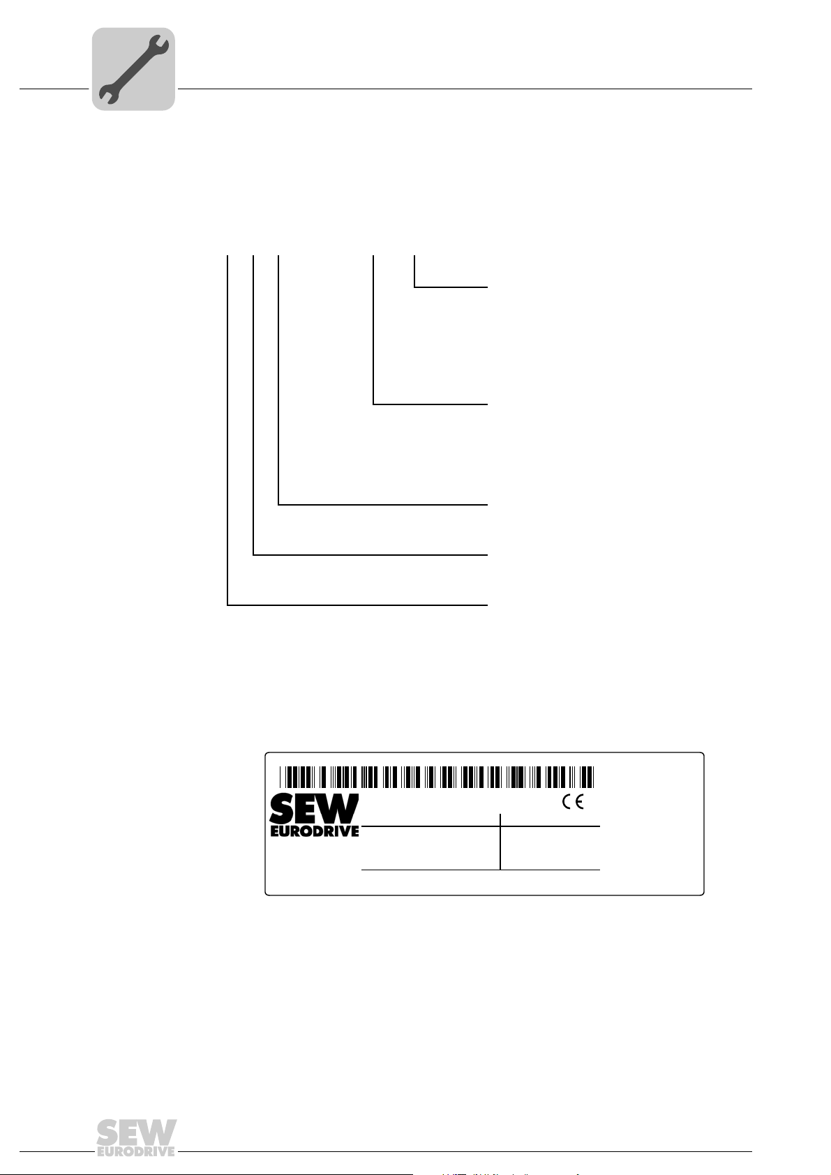
2.1 Type designation
The type designation of the MOVIPRO® PZM2xA-A...-...-00 power interface comprises
the following characteristic data:
PZM2 xA-A ... - ... - 00
MOVIPRO® connection:
D02 = Disconnection switch up to 25 A
D03 = Disconnection switch up to 40 A
M13 = Line and unit protection up to 5 A
M14 = Line and unit protection up to 9 A
M16 = Line and unit protection up to 15 A
Maximum switching capacity:
022=2.2kW
040 = 4.0 kW
075 = 7.5 kW
150 = 15.0 kW
2.2 Nameplate
Housing height:
2 = 110 mm
Typ e:
ZM = Power interface accessories
Product range:
P = MOVIPRO
®
Each unit has a nameplate that provides important information. The following figure
shows an example of a nameplate:
6
Type Type designation SO# Production number
I Max.current carrying capacity P Max. switching capacity
Addendum to the Operating Instructions – MOVIPRO®
2081785611
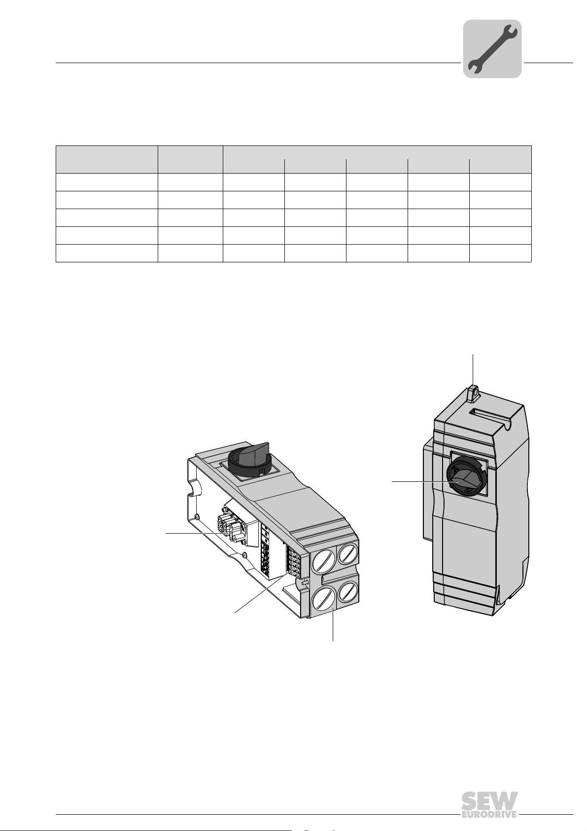
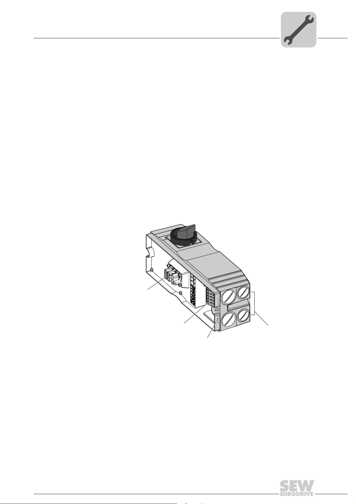
2.3 Power interface assignment
[2]
[3]
[1]
[5]
[4]
PZM2xA-A...-...-00 Power Interface
Power interface assignment
2
The following overview illustrates the assignment of the individual power interfaces to
the respective MOVIPRO
Power interface Part number
PZM2xA-A075-D02-00 1 825 014 9
PZM2xA-A150-D03-00 1 825 015 7
PZM2xA-A022-M13-00 1 825 023 8
PZM2xA-A040-M14-00 1 825 016 5
PZM2xA-A075-M16-00 1 825 017 3
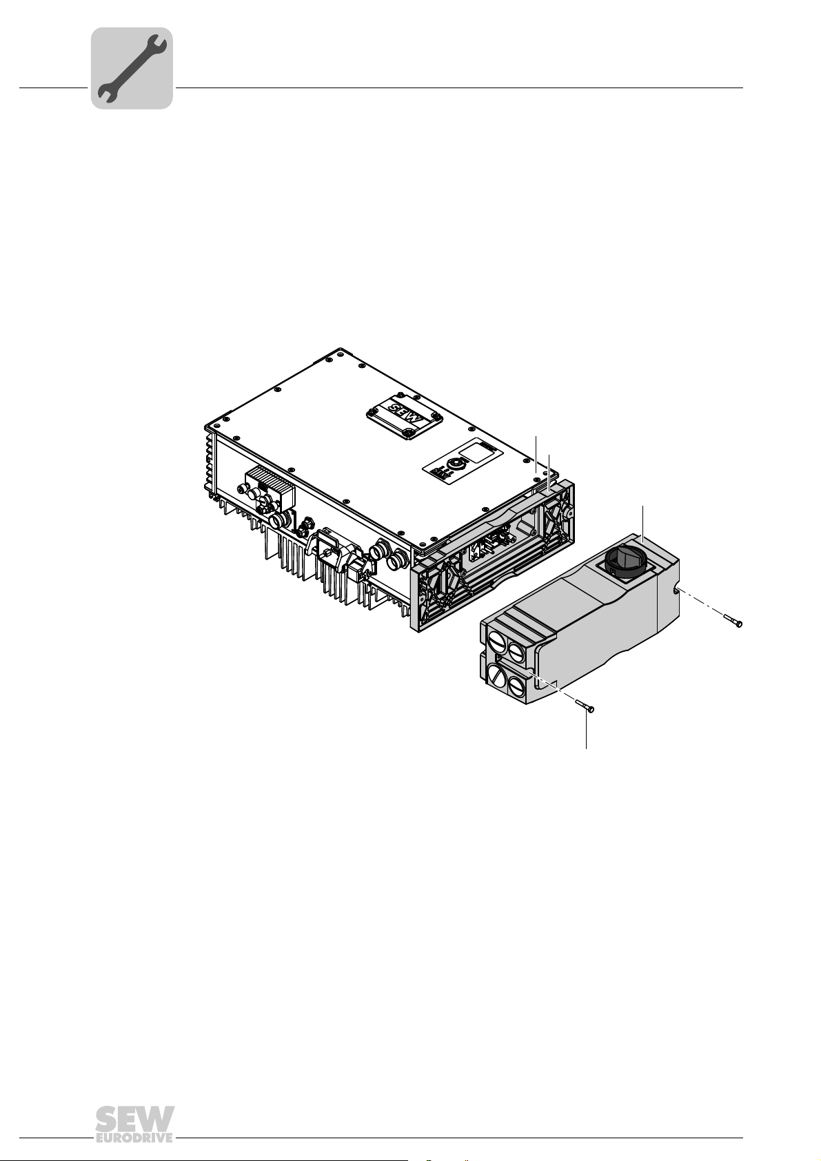
2.4 Basic unit
The following figure shows the power interface:
®
units:
MOVIPRO
up to 2.2 kW up to 4.0 kW up to 7.5 kW up to 11.0 kW up to 15.0 kW
®
•••
•••••
•
•
•
[1] MOVIPRO
[2] Power input terminal strip X1
[3] Front panel connectors
[4] Maintenance switch
Addendum to the Operating Instructions – MOVIPRO®
®
connection (Han® 10 B, female) [5] Suspension device (for storing the power interface
during a MOVIPRO
ple)
2048160523
®
unit replacement, for exam-
7
2
PZM2xA-A...-...-00 Power Interface
Scope of functions
2.5 Scope of functions
2.6 Maintenance switch
The power interface allows for the following functions:
• Connection to the AC 400 V supply system
• Connection to the 24 V backup voltage
• DC 24 V output of the integrated power supply for the MOVIPRO
external DC 24 V cabling (jumper with DC 24 V backup voltage)
• Connected voltages are looped through
• Disconnection of the MOVIPRO
The maintenance switch of the power interface is used to disrupt the AC 400 V power
supply in the power face. The maintenance switch can be secured with 3 locks.
If the maintenance switch is in position "0", the MOVIPRO
AC 400 V voltage supply.
®
unit via the maintenance switch
®
®
self-supply without
is disconnected from the
10 minutes
WARNING
Electric shock due to dangerous voltages present in the power interface.
Severe or fatal injuries.
• Disconnect the power interface from the power supply before you perform any work
on the unit.
• Observe a minimum switch-off time of 10 minutes after disconnecting the power
supply.
INFORMATION
When there is a valid enable signal pending for the MOVIPRO®, the motor is supplied
with current as soon as the maintenance switch is set to 1.
NOTICE
Increased wear of the switch contacts.
Damage of the switch contacts.
• Do not operate the maintenance switch under load.
Depending on the respective type, the power interfaces are equipped with different
maintenance switches:
• D.. disconnection switch
• M.. line and unit protection
8
Addendum to the Operating Instructions – MOVIPRO®
PZM2xA-A...-...-00 Power Interface
Power interface – mechanical installation
2.6.1 D.. disconnection switch
The following disconnection switches are possible depending on the unit's power rating:
Power Short designation Description
up to 7.5 kW D02 Disconnection switch up to 25 A
up to 15.0 kW D03 Disconnection switch up to 40 A
2.6.2 M.. line and unit protection
The following line and unit protection is possible depending on the power:
Power Short designation Description
up to 2.2 kW M13 line and unit protection up to 5 A
up to 4.0 kW M14 line and unit protection up to 9 A
up to 7.5 kW M16 line and unit protection up to 15 A
2.7 Power interface – mechanical installation
2
2.7.1 General information
Observe the following notes on mechanical installation:
• Observe the general safety notes.
• Strictly observe all instructions as to the technical data and the permissible conditions regarding the place of installation.
• Do only use provided attachment options when mounting the unit.
2.7.2 Minimum clearance
Observe the required minimum clearance for:
• the connection of the cables and plug connectors
• the operation of the respective devices such as the maintenance switches.
For the dimensions of the required minimum clearances, refer to chapter "Technical
data (page 17)".
Addendum to the Operating Instructions – MOVIPRO®
9
2
[1]
[2]
[4]
[3]
PZM2xA-A...-...-00 Power Interface
Power interface – mechanical installation
2.7.3 Mounting the power interface
Use the following enclosed parts for assembly:
• 2 × M5 × 30 SW8 screws
Mount the power interface on the right side of the MOVIPRO
unit front).
Proceed as follows to mount the unit:
1. Make the required connections at the connection panel of the power interface, e.g.
AC 400 V supply cable and DC 24 V backup voltage.
®
unit (as viewed onto the
10
[1] MOVIPRO
[2] Power interface flange [4] M5 × 30 SW8 screws
2. Connect the plug connector of the power interface to the plug connector of the
MOVIPRO
®
®
.
3. Attach the power interface to the MOVIPRO
screws with 1.6 Nm – 1.8 Nm (14 in-lb – 16 in-lb).
Addendum to the Operating Instructions – MOVIPRO®
[3] Power interface
®
by tightening the two M5 × 30 SW8
2062166283
PZM2xA-A...-...-00 Power Interface
[1]
[2]
[3]
[4]
Power interface – electrical installation
2.8 Power interface – electrical installation
2.8.1 General Information
Observe the following notes on electrical installation:
• Observe the general safety notes.
• Strictly observe all instructions as to the technical data and the permissible conditions regarding the place of installation.
2.8.2 Cable routing
Comply with the following points when installing the cables:
• Use suitable cables to connect the power supply and the communication.
• Route power cables and signal cables in separate cable ducts.
• Maintain the greatest possible distance between power cables and signal cables.
• Avoid using long cables running parallel to one another.
2
2.8.3 Power interface connections
The following table shows the connections of the power interface:
[1] MOVIPRO
[2] Power input terminal strip X1
[3] Gland (M32 ×1.5)
[4] Gland (M25 ×1.5)
®
connection (Han-Modular® 10 B, female)
1954903947
Addendum to the Operating Instructions – MOVIPRO®
11
2
CA
8
12
1
562
1
562
4
7
3
8
4
7
3
3
PZM2xA-A...-...-00 Power Interface
Power interface – electrical installation
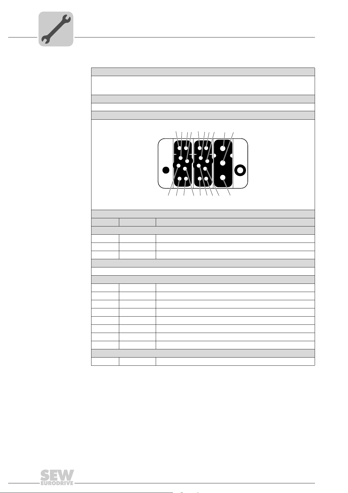
Connection to
MOVIPRO
®
The following table provides information about this connection:
Function
• AC 400 V input to supply units up to
15.0 kW
• DC 24 V output and input
Connection type
Han-Modular® 10 B, female
Wiring diagram
Assignment
No. Name Function
[a] Han®C module, male
1 L1 Supply system phase 1
2 L2 Supply system phase 2
3 L3 Supply system phase 3
[b] Han®EE module, male
Coding of the unit power, see section coding (page 13)
[c] Han®EE module, male
1 +24V_C DC 24 V input – backup voltage
2 SC Signal contact for maintenance switch (external)
3 VO24 DC 24 V output
4 n.c. Not connected
5 0V24_C 0V24 reference potential – backup voltage
6 n.c. Not connected
7 GND Reference potential
8 n.c. Not connected
Hinged frame
PE PE PE connection
• With signal contact for external maintenance switch
• For connecting a power interface (PZM)
2365614987
12
Addendum to the Operating Instructions – MOVIPRO®

PZM2xA-A...-...-00 Power Interface
CA
1562
8374
Power interface – electrical installation
2
Coding The following table shows the assignment of the different coding to the respective power
1562
1562
®
units:
8374
®
interfaces and the corresponding MOVIPRO
Power interface Power interface – coding of the connections MOVIPRO
CA
PZM2xA-A022-M13-00 2.2 kW
PZM2xA-A040-M14-00 4.0 kW
CA
PZM2xA-A075-M16-00 7.5 kW
8374
1562
CA
2.2 kW
PZM2xA-A075-D02-00
4.0 kW
7.5 kW
8374
1562
CA
2.2 kW
4.0 kW
PZM2xA-A150-D03-00
7.5 kW
11. 0 k W
15.0 kW
Addendum to the Operating Instructions – MOVIPRO®
8374
13
2
VO24
DGND
+24V_C
0V24_C
HT1
HT2
L3
VO24
DGND
+24V_C
0V24_C
HT1
HT2
L3
PZM2xA-A...-...-00 Power Interface
Power interface – electrical installation
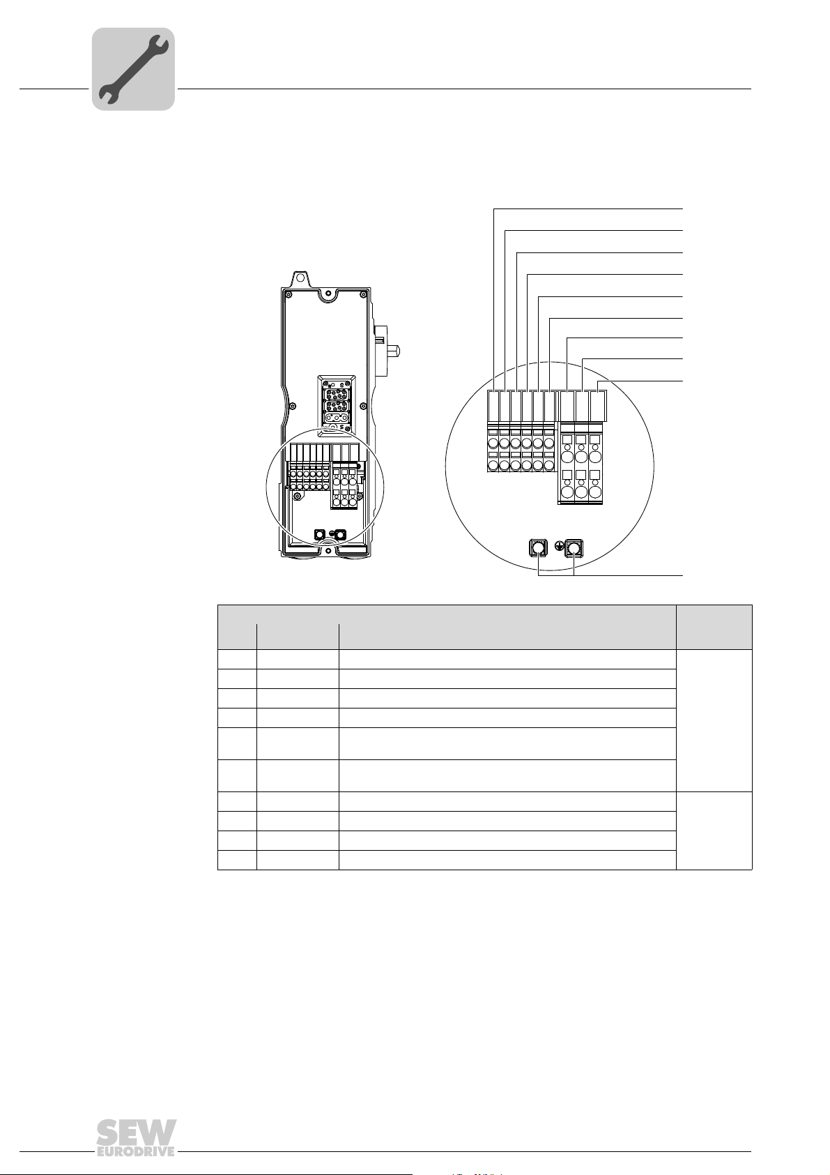
2.8.4 X1 terminal strip of the power interface
The following table shows the connections of the power interface:
[1]
[2]
[3]
[4]
[5]
[6]
[7]
[8]
[9]
0V24_C
HT1
HT2
L1L1L2L2L3
VO24
DGND
+24V_C
VO24
L1L1L2L2L3
DGND
+24V_C
0V24_C
HT1
HT2
[10]
9007201210059403
Terminal strip X1 (power input terminal strip) Terminal
No. Name Function
cross
section
1 VO24 DC 24 V output
2 GND Reference potential / DC 24 V output
3 +24 V_C DC 24 V input
4 0V24_C 0V24 reference potential – input
6mm
2
5 HT1 Auxiliary terminal for additional voltage levels (without internal
function)
6 HT2 Auxiliary terminal for additional voltage levels (without internal
function)
7 L1 Phase L1
8 L2 Phase L2
9 L3 Phase L3
10 mm
2
10 PE Equipotential bonding/protective earth conductor
14
Addendum to the Operating Instructions – MOVIPRO®

PZM2xA-A...-...-00 Power Interface
12 3
4
12 3
4
Power interface – electrical installation
2
DC 24 V supply The MOVIPRO® is equipped with a DC 24 V output that can be used to supply the
MOVIPRO
®
from the DC link.
To use the 24 V supply from the DC link, you must jumper the following terminals:
• 1 with 3
• 2 with 4
The following figure illustrates the wiring for using the 24 V supply from the DC link:
2165934475
To use an external DC 24 V backup voltage, connect it to the following terminals:
•3
•4
In this case, the terminals 1 and 2 must not be used.
The following figure illustrates the wiring for using an external 24 V supply:
2165930891
Addendum to the Operating Instructions – MOVIPRO®
15

2
PZM2xA-A...-...-00 Power Interface
Power interfaces – technical data
2.9 Power interfaces – technical data
2.9.1 Basic unit
The following table lists the technical data for the PZM2xA-A...-...-00 power interfaces:
Power interface
PZM2xA-A022M13-00
Description
Ambient temperature
Derating
Ambient temperature ϑ
Climate class EN 60721-3-3, class 3K3
Storage temperature ϑ
Degree of protection IP20, IP54 (in assembled state)
Weight 2.5 kg (5.5 lb)
Dimensions W × H × D 139 mm × 116 mm × 341 mm (5.47 in × 4.57 in × 13.43 in)
Unit output to MOVIPRO
Max. output current 5 A 9 A 15 A 25 A 40 A
Integrated unit protection 5 A 9 A 15 A – –
Max. switching capacity
(IEC, AC 3)
Max. switching capacity
(UL, DOL rating)
Unit input
Line voltage V
Line frequency f
Supply system terminal
cross section
24 V terminal cross
section
Maximum permitted fuse
(gL characteristics)
1) For UL-compliant installation, also observe the maximum permitted fuse for the connected MOVIPRO®. Always adhere to the smaller
value.
line
line
2.2 kW with line
and unit
protection
U
L
®
2.2 kW 4.0 kW 7.5 kW 7.5 kW 15.0 kW
– – – 7.5 HP 15.0 HP
PZM2xA-A040M14-00
4kW with line
and unit
protection
(non-condensing, no moisture condensation)
2
2.5 mm
– 10 mm2 (flexible with conductor end sleeve)
2
1.5 mm
– 6 mm2 (flexible with conductor end sleeve)
60 A 35 A
PZM2xA-A075M16-00
7.5 kW with line
and unit
protection
+5 – +40°C (+41 – +104 °F)
PN reduction: 3% IN per K
up to 60 °C (140 °F)
−25 –+70 °C (−13 – 158 °F)
3 AC 380 V – 500 V
50 – 60 Hz ± 5%
PZM2xA-A075D02-00
7.5 kW with
disconnection
switch
1)
PZM2xA-A150D03-00
15 kW with
disconnection
switch
50 A
1)
16
Addendum to the Operating Instructions – MOVIPRO®

2.9.2 Power interface – dimension drawings
The dimension drawings show the mechanical dimensions of the power interface
in mm (in):
M32 × 1.5 (2×)
PZM2xA-A...-...-00 Power Interface
Power interfaces – technical data
M25 × 1.5 (2×)
2
SW 8
341 (13.43)
361 (14.21)
44 (1.7)
10 (0.39)
139 (5.47)
Ø 10 (0.39)
122 (4.80)
2.9.3 Additional information
Standards and
certifications
Addendum to the Operating Instructions – MOVIPRO®
The power interface was developed and tested based on the following standards:
• VDE 0100
• EN 50178
152 (5.98)
2052458379
17

3
Sensor/Actuator Box
3 Sensor/Actuator Box
The sensor/actuator box allows for connecting up to 8 sensors/actuators to the
MOVIPRO
The sensor/actuator box provides one connection cable with M23 plug connector and
M12 sockets for the sensors or actuators [1]. The green LED "P" [2] indicates that the
DC 24 V supply voltage is used. Each M12 socket is equipped with a yellow LED for
displaying the status of the inputs/outputs [3].
The following figure shows the sensor/actuator box:
®
unit. It occupies only one connection for digital I/Os of the MOVIPRO® unit.
[3]
[2]
[1]
45035997344566411
[1] M12 socket
[2] Operating display LED
[3] Display status of inputs/outputs
The sensor/actuator box is available with different connection cable lengths.
18
Addendum to the Operating Instructions – MOVIPRO®

Sensor/Actuator Box
Sensor/actuator box – electrical installation
3.1 Sensor/actuator box – electrical installation
3.1.1 Signals
Connection The following table informs about this connection:
Function
®
Signal transmission to a MOVIPRO
Connection type
M23, P insert 12-pole, female, 0°-coded
Wiring diagram
unit
9
1
10
2
3
8
12
7
3
4
11
Assignment
No. Name Function
1 0 Signal 0
2 1 Signal 1
3 2 Signal 2
4 3 Signal 3
5 4 Signal 4
6 5 Signal 5
7 6 Signal 6
8 7 Signal 7
9 0V24 0V24 reference potential
10 0V24 0V24 reference potential
11 +24V DC 24 V output
12 FE Equipotential bonding/functional ground
6
5
2264822027
Addendum to the Operating Instructions – MOVIPRO®
19

3
Sensor/Actuator Box
Technical data of the sensor/actuator box
Connection cables The following table shows the available cable lengths for the sensor/actuator box:
Connection cable and component
Cable
Length 1 m: Part no. 1 330 926 9
Length 2 m: Part no. 1 330 927 7
Length 3 m: Part no. 1 330 928 5
Length 5 m: Part no. 1 330 929 3
Length 10 m: Part no. 1 330 930 7
Cable design: (3X0.75+8X0.34)
Length/
Installation type
Fixed length
M23, 12-pole, male,
0°-coded
3.2 Technical data of the sensor/actuator box
The following tables show the technical data of the sensor/actuator box:
Nominal voltage V
Maximum operating voltage V
Current carrying capacity
per slot 4 A
in total 8 A
Operating voltage display Green LED
Status display Yellow LED (signal 1)
Operating current display
elements
Degree of protection IP65 (with screwed plug connectors)
[A] = 1 m
Ambient temperature
for fixed routing –30 – +80 °C (–22 – +176 °F)
for cable carrier –5 – +70 °C (–23 – +158 °F)
Cable type Main cable suitable for cable carriers
N
max
Connection cables
(3 ft)
Basic unit
[A] = 2 m
(7 ft)
Sensor/actuator box
(8 M12 slots)
DC 24 V
DC 30 V
≤ 5 mA
[A] = 3 m
(10 ft)
[A] = 5 m
(20 ft)
[A] = 10 m
(33 ft)
20
Addendum to the Operating Instructions – MOVIPRO®

3.2.1 Wiring
Sensor/Actuator Box
Technical data of the sensor/actuator box
The following figure shows the wiring of the sensor/actuator box:
3
0V 1/4
3
5
2/4 6/4 7/4 8/4
4
1
12 678
4
3
1
5
4
3
1
5
4
3
1
5
4
3
5
1
U
h
1214655371
Addendum to the Operating Instructions – MOVIPRO®
21

3
3.2.2 Dimension drawing
Sensor/Actuator Box
Technical data of the sensor/actuator box
The dimension drawing shows the mechanical dimensions of the sensor/actuator box in
mm (in):
[A]
32 (1.3)
50 (2.0)
9 (0.4)
39 (1.5)
17 (0.7)
140 (5.5)
107 (4.2)
73 (2.9)
33 (1.3)
4.5 (0.2)
Ø 4.5 (0.2)
9007200325600523
22
Addendum to the Operating Instructions – MOVIPRO®

BW..-0..-0. External Braking Resistors
4 BW..-0..-0. External Braking Resistors
WARNING
Electric shock due to high DC voltage in the supply lines (about DC 900 V).
Severe or fatal injuries.
• Only use cables provided by SEW-EURODRIVE.
• Install the braking resistor cables according to the regulations.
WARNING
Hot surfaces.
Risk of injuries and fire.
• Select a suitable installation location and observe the minimum clearance.
• Provide for covers to secure hot surfaces.
• Install the protection devices according to the regulations.
• Check the protection devices on a regular basis.
For regenerative operation, the MOVIPRO® is connected to an external braking resistor.
The following figure shows an example of a size 1 braking resistor:
4
INFORMATION
The BW...-0..-0. braking resistors are intrinsically safe. This kind of intrinsic safety
does explicitly not correspond to the kind of intrinsic safety referred to in conjunction
with explosion-protection.
With the BW...-0..-0. braking resistors, intrinsic safety means that the following does
not occur in the event of a continuous overload (e.g. due to a short circuit in the
braking transistor (brake chopper)):
• Short circuit
• Short circuit to frame
•Fire
•Explosion
• Melting of the aluminum housing
Addendum to the Operating Instructions – MOVIPRO®
2084027019
23

4
BW..-0..-0. External Braking Resistors
Braking resistors – mechanical installation
4.1 Braking resistors – mechanical installation
4.1.1 Mounting position
The following table shows the permitted and prohibited mounting positions for the
braking resistors:
Braking resistor Mounting positions
BW100-004-00
BW033-012-01
BW050-008-01
BW017-024-02
4.1.2 Minimum clearance
Calculate the mounting surfaces, the touch guard and the clearance according to the
high surface temperature. However, observe a minimum clearance of 30 mm. For the
dimensions of the required minimum clearances, refer to chapter "Technical data of the
external braking resistors (page 30)".
24
Addendum to the Operating Instructions – MOVIPRO®

4.1.3 Mounting braking resistors
You can mount the braking resistors directly over the retaining plates. Note the following
points during assembly:
• Observe the safety notes.
• Observe the required minimum distances and clearances.
Use the following parts for assembly:
• A mounting plate, for example, to observe the required minimum distances and
clearances
• Suitable mounting and safety elements
Mount the braking resistors as follows:
1. For dimensions of the holes, refer to the dimension sheets in the technical data of the
braking resistors.
2. Drill the holes in the appropriate places.
3. The following figures show how to mount the braking resistors:
Size 0:
BW..-0..-0. External Braking Resistors
Braking resistors – mechanical installation
4
Addendum to the Operating Instructions – MOVIPRO®
2110859403
25

4
1. 2.
BW..-0..-0. External Braking Resistors
Braking resistors – mechanical installation
Sizes 1 and 2:
4. Ground the housing of the braking resistor.
2110862475
26
Addendum to the Operating Instructions – MOVIPRO®

BW..-0..-0. External Braking Resistors
[3]
[1]
[2]
Braking resistors – mechanical installation
4.1.4 Mounting the braking resistors with mounting brackets (only size 1 and 2)
You can use the following mounting brackets to attach the braking resistors:
• BW050-008-01
• BW033-012-01
• BW017-024-02
Note the following points during assembly:
• Observe the safety notes.
• Observe the required minimum distances and clearances.
Use the following parts for assembly:
• The SEW-EURODRIVE "BW bracket mounting set" accessory, part number
1 822 968 9. It contains:
– 4 × mounting brackets
– 8 × M5 × 12 pan head screws
Proceed as follows to attach the mounting brackets:
1. Use the M5 × 12 pan head screws [1] to attach the mounting brackets [3] to the
braking resistor [2] according to the following figure:
4
[1] M5 × 12 pan head screws [2] Braking resistor [3] Mounting brackets
2. Ground the housing of the braking resistor.
INFORMATION
For information on how to attach the brackets to square pipes or bars, refer to chapter
"Mounting accessories (page 36)".
Addendum to the Operating Instructions – MOVIPRO®
2091901579
27

4
BW..-0..-0. External Braking Resistors
Technical data of the external braking resistors
4.2 Technical data of the external braking resistors
4.2.1 Braking resistor assignment
The following table illustrates the assignment of external braking resistors to the respective MOVIPRO
Braking
resistor
BW100-004-00 1 796 218 8 Size 0
BW050-008-01 1 796 224 2 Size 1 6 mm
BW033-012-01 1 796 219 6 Size 1 6 mm
BW017-024-02 1 796 221 8 Size 2 6 mm
Part
number
Size
®
units:
Terminal
cross
section
up to
2.2 kW
up to
4.0 kW
MOVIPRO
7.5 kW
up to
®
up to
11.0 kW
up to
15.0 kW
•••
2
2
2
••••
••••
••
28
Addendum to the Operating Instructions – MOVIPRO®

BW..-0..-0. External Braking Resistors
Technical data of the external braking resistors
4.2.2 Technical data according to IEC
The following tables list the technical data of the external braking resistors according to
IEC:
Braking resistor
BW100-004-00 BW050-008-01 BW033-012-01 BW017-024-02
Function Carrying off of regenerative energy
Degree of protection IP65
Resistance 100 Ω 50 Ω 33.3 Ω 16.7 Ω
Continuous braking
power
Dimensions W × H × D 320 mm × 70 mm × 106 mm 550 mm × 105 mm × 230 mm 550 mm × 158 mm × 330 mm
100% cdf 0.4 kW 0.8 kW 1.2 kW 2.4 kW
50% cdf 0.8 kW 1.6 kW 2.4 kW 4.8 kW
25% cdf 1.5 kW 3.0 kW 4.5 kW 9.0 kW
12% cdf 2.2 kW 4.4 kW 6.6 kW 13.2 kW
6% cdf 3.6 kW 7.2 kW 10.8 kW 21.6 kW
4
4.2.3 Technical data according to UL
The following tables list the technical data of the external braking resistors:according to
UL:
Braking resistor
BW100-004-00 BW050-008-01 BW033-012-01 BW017-024-02
Function Carrying off of regenerative energy
Degree of protection IP65
Resistance 100 Ω 50 Ω 33.3 Ω 16.7 Ω
Continuous braking
power
Dimensions W × H × D
100% cdf 0.24 kW 0.48 kW 0.72 kW 1.44 kW
50% cdf 0.5 kW 1.0 kW 1.5 kW 3.0 kW
25% cdf 1.0 kW 2.0 kW 3.0 kW 6.0 kW
12% cdf 2.2 kW 4.4 kW 6.6 kW 13.2 kW
6% cdf 3.6 kW 7.2 kW 10.8 kW 21.6 kW
320 mm × 70 mm × 106 mm
(12.6 in × 2.8 in × 4.17 in)
550 mm × 105 mm × 230 mm
(21.7 in × 4.13 in × 9.06 in)
550 mm × 158 mm × 330 mm
(21.7 in × 6.22 in × 13.0 in)
Addendum to the Operating Instructions – MOVIPRO®
29

4
86 (3.4)
10 (0.39)
10 (0.39)
Ø 6
(0.2)
10 (0.39)
300 (11.8)
70 (2.8)
ca. 1580 (62.20)
320 (12.6)
106 (4.17)
4.2.4 Braking resistors – dimension drawings
Size 0 braking
resistor
BW..-0..-0. External Braking Resistors
Technical data of the external braking resistors
The dimension drawing shows the mechanical dimensions of the size 0 braking resistor
in mm (in):
2062332427
30
Addendum to the Operating Instructions – MOVIPRO®

BW..-0..-0. External Braking Resistors
Technical data of the external braking resistors
4
Size 1 braking
resistor
Ø 9 (0.4)
(2×)
215 (8.46)
15 (0.59)
12 (0.47)
The dimension drawing shows the mechanical dimensions of the size 1 braking resistor
in mm (in):
230 (9.06)
542 (21.3)
9 (0.4)
105 (4.13)
550 (21.7)
v
M5
15 (0.59)
2062339339
Addendum to the Operating Instructions – MOVIPRO®
31

4
BW..-0..-0. External Braking Resistors
Technical data of the external braking resistors
Size 2 braking
resistors
Ø 9 (0.4)
315 (12.4)
(3×)
165 (6.50)
12 (0.47)
The dimension drawing shows the mechanical dimensions of size 2 braking resistors in
mm (in):
330 (13.0)
15 (0.59)
542 (21.3)
9 (0.4)
158 (6.22)
550 (21.7)
M5
15 (0.59)
2062328587
32
Addendum to the Operating Instructions – MOVIPRO®

5 Jumper Plug
Safe disconnection of the unit is not possible when the jumper plug is used.
Severe or fatal injuries.
• Use the jumper plug only if the unit need not perform any safety functions according
WARNING
to DIN EN ISO 13849-1.
Jumper Plug
5
The jumper plug can be connected to the X5502 terminal of MOVIPRO®. The jumper
plug deactivates the safety functions of the MOVIPRO
The following figure shows the jumper plug, part number 1 174 709 9:
®
.
36028798167876875
Addendum to the Operating Instructions – MOVIPRO®
33

6
[2]
[1]
a
Mounting Accessories
Handles
6 Mounting Accessories
6.1 Handles
You can equip the MOVIPRO® with handles for easier handling:
The handles are available in two lengths depending on the size of MOVIPRO
2049840395
®
:
Handles Part number MOVIPRO® housing height
Handle option 270 1 822 278 1 (2 pieces) 300 mm
Handle option 390 1 822 280 3 (2 pieces) 420 mm
6.1.1 Mounting the handles
Tighten both countersunk screws of each handle with a maximum tightening torque of
3.5 Nm (31 in-lb).
34
1531247243
[1] M8 × 20 countersunk screw (DIN EN ISO 10642) a = Handle option = 270 mm
[2] Handle Handle option = 390 mm
Addendum to the Operating Instructions – MOVIPRO®

6.2 Mounting brackets
You can use mounting brackets to mount the MOVIPRO® safely and easily:
Mounting Accessories
Mounting brackets
6
658542347
Mounting brackets Part number
MOVIPRO
Braking resistors:
BW050-008-01
BW033-012-01
BW017-024-02
®
Mounting bracket kit, large (4 pieces) 1 270 830 5
Mounting bracket kit, BW (4 pieces) 1 822 968 9
For information on how to mount the braking resistors with the mounting brackets, refer
to chapter "Braking resistors – mechanical installation (page 24)".
Addendum to the Operating Instructions – MOVIPRO®
35

6
Mounting Accessories
Mounting brackets
6.2.1 Mounting with mounting brackets
Note the following points during assembly:
• Strictly observe the safety notes contained in this documentation.
• Observe the required minimum distances and clearances.
Use the following parts for assembly:
• The SEW-EURODRIVE "Large bracket mounting set" accessory, part number
1 270 830 5. It contains:
– 4 mounting brackets
– 8 studs M5 × 8 type in accordance with DIN EN ISO 4027
• Suitable mounting and retaining elements to attach the MOVIPRO
fixture:
– e.g. M6 or M8 screws of an appropriate length with washers
Mounting brackets Proceed as follows to attach the mounting brackets to the MOVIPRO
1. Insert the mounting brackets into the T-slots of the MOVIPRO
edge of the bracket is flush with the upper end of the slot.
2. In order to prevent the mounting brackets from slipping out of position in the T-slots,
you can fasten them with M8 × 30 screws in the through bores of the MOVIPRO
®
unit to the
®
unit:
®
unit so that the upper
®
.
Preparing the
fixture
3. Fasten the mounting bracket with the enclosed studs.
Square pipes or bars can be used as a fixture for the MOVIPRO
®
.
INFORMATION
Use only square pipes with an edge length ≤ 35 mm for mounting the MOVIPRO® unit
to avoid mechanical interference.
Proceed as follows to prepare the fixture:
1. Refer to the following table for dimensions of the threaded holes in the holding fixture:
Bore dimension Value
X
2
2. Cut the threads at the appropriate points.
3. For the clearance dimensions of the fixture, refer to the following table:
Distance Value
A Housing dimension Y – 145 mm (5.71 in) (see dimension drawing)
4. Mount the holding fixture within the calculated clearance.
Housing dimension X – 30 mm (1.2 in) (see dimension drawing)
36
Addendum to the Operating Instructions – MOVIPRO®

Mounting Accessories
Mounting brackets
6
Fastening
MOVIPRO
®
1. Use the mounting brackets to hang the MOVIPRO
®
on the fixture.
2. Screw the mounting brackets to the fixture. The following figure illustrates suitable
mounting and locking elements. It shows the main mounting elements and dimensions in mm (in):
[1]
[2]
[4]
[5]
[6]
[5]
[4]
[7]
[8]
Proceed as follows to fasten the unit to the fixture:
86.5 (3.41)
X
X
2
[1] MOVIPRO
[2] Large mounting brackets
[3] Holding fixture, e.g. square pipe or bar
Bore for:
[4] M8 × 30 screw
[5] M5 × 8 stud
[6] M8 screw of an appropriate length with washer
[7] M6 screws with suitable length with washer through bore [7] and [8]
X, Y Housing dimensions
X
2
A Distance
67.5 (2.66) 77.5 (3.05)
A
Y
®
Bore dimension
20 (0.79)
M8
10 (0.39)
(1.59)
15 (0.59)
Ø
6.6 (0.26)
Ø
M6
40.5
66 (2.6)
114.5 (4.508)
M5
M5
20 (0.79)
10 (0.39)
95 (3.7)
115 (4.53)
14.6 (0.575)
20 (0.79)
36028797434827531
[2]
135 (5.31)
Maximum permitted tightening torque: 3.2 Nm (28 in-lb)
Addendum to the Operating Instructions – MOVIPRO®
37

7
[3][2][1]
Fan Subassembly
7 Fan Subassembly
The fan is connected to the MOVIPRO® externally. The axial fans are controlled automatically depending on the temperature. They are encapsulated, and their degree of
protection is IP54.
The following figure shows the fan subassembly:
[1] Air baffle
[2] Connection cable
[3] Axial fan
Part number
Fan subassembly 1 270 970 0
36028797698977163
38
Addendum to the Operating Instructions – MOVIPRO®

Mechanical installation of the fan subassembly
[1]
[2]
[4]
[3]
7.1 Mechanical installation of the fan subassembly
Use the following enclosed parts for assembly:
• 6 screws M5 × 75
• 6 serrated lock washers
Proceed as follows to mount the fan subassembly:
1. Use the M5 × 75 screws [4] and the serrated lock washers to mount the fan subassembly [3] according to the following figure:
Fan Subassembly
7
9007201339415307
[1] X5111 connector of MOVIPRO® [3] Fan subassembly
[2] MOVIPRO
2. Plug the connector of the fan cable onto the X5111 connector [1] of MOVIPRO
®
[4] M5 × 75 screws
®
[2].
Addendum to the Operating Instructions – MOVIPRO®
39

Index
Index
A
AC 400 V input
Connection.........................................................12
Assignment
External braking resistors ..................................28
Power interface ....................................................7
B
Basic unit
Power interface ....................................................7
Brackets .................................................................35
Part number .......................................................35
Braking resistors, see external braking resistors ...23
BW017-024-02.......................................................23
BW033-012-01.......................................................23
BW050-008-01.......................................................23
BW100-004-00.......................................................23
C
Cable routing
Power interface ..................................................11
Cables
see connection...................................................20
Certifications
Power interface ..................................................17
Connection
AC 400 V input...................................................12
Digital inputs/outputs..........................................19
Connections ...........................................................14
Power interface ..................................................11
Control unit, see Communication and control unit .19
Copyright..................................................................5
D
Digital inputs/outputs
Connection.........................................................19
Digital I/Os, control unit
Cables................................................................20
Dimension drawings
External braking resistors ..................................30
Power interface ..................................................17
Sensor/actuator box...........................................22
Disconnection switch
D02/D03...............................................................9
Power interface ....................................................9
E
Electrical Installation
Sensor/actuator box........................................... 19
Electrical installation
Power interface.................................................. 11
Embedded safety notes ........................................... 4
Exclusion of liability..................................................5
External Braking resistors
Mounting brackets ............................................. 27
External braking resistors ......................................23
Assignment ........................................................ 28
Dimension drawings .......................................... 30
IEC data............................................................. 29
Mechanical installation....................................... 24
Minimum clearance............................................ 24
Mounting ......................................................25, 27
Mounting position............................................... 24
Part numbers ..................................................... 28
UL data .............................................................. 29
F
Fan subassembly...................................................38
Mechanical installation....................................... 39
Part number .......................................................38
Functions
Power interface.................................................... 8
H
Handle option.........................................................34
Mounting ............................................................ 34
Part numbers ..................................................... 34
Handles..................................................................34
Part numbers ..................................................... 34
I
IEC data
External braking resistors ..................................29
Installation, mechanical ...........................................9
I/O, see Digital inputs/outputs................................ 19
J
Jumper plug ...........................................................33
Part number .......................................................33
40
Addendum to the Operating Instructions – MOVIPRO®

Index
M
Maintenance switch
Power interface ....................................................8
Mechanical Installation.............................................9
Mechanical installation
External braking resistors ..................................24
Fan subassembly...............................................39
Power interface ....................................................9
Minimum clearance
External braking resistance................................24
Power interface ....................................................9
Motor protection switch
M14/D16 ..............................................................9
Power interface ....................................................9
Mounting
External braking resistors ............................25, 27
Handle option.....................................................34
Power interface ..................................................10
Mounting accessories ............................................34
Brackets .............................................................35
Handle option.....................................................34
Handles..............................................................34
Mounting brackets..............................................35
Mounting bracket
Use.....................................................................36
Mounting brackets..................................................35
External braking resistors ..................................27
Part numbers .....................................................35
Mounting position
External braking resistors ..................................24
Mounting with mounting brackets...........................36
N
Nameplate
Power interface ....................................................6
Notes
Designation in the documentation........................4
P
Part number
Jumper plug .......................................................33
Part numbers
Brackets............................................................. 35
External braking resistors ..................................28
Fan subassembly............................................... 38
Handle option..................................................... 34
Handles.............................................................. 34
Mounting brackets ............................................. 35
Sensor/actuator box........................................... 20
Power input, see AC 400 V input...........................12
Power interface
Assignment .......................................................... 7
Basic unit ....................................................... 7, 16
Cable routing ..................................................... 11
Certifications ...................................................... 17
Dimension drawings .......................................... 17
Disconnection switch ........................................... 9
Electrical installation .......................................... 11
Functions ............................................................. 8
Maintenance switch ............................................. 8
Mechanical installation......................................... 9
Minimum clearance.............................................. 9
Motor protection switch........................................9
Mounting ............................................................ 10
Nameplate ...........................................................6
PZM2xA-A022-M13-00 .................................... 6, 7
PZM2xA-A040-M14-00 ..............................6, 7, 16
PZM2xA-A075-D02-00 .............................. 6, 7, 16
PZM2xA-A075-M16-00 ..............................6, 7, 16
PZM2xA-A150-D03-00 .............................. 6, 7, 16
Standards .......................................................... 17
Technical data ................................................... 16
Type designation ................................................. 6
power interface
PZM2xA-A022-M13-00 ...................................... 16
PZM2xA-A022-M13-00 .................................. 6, 7, 16
PZM2xA-A040-M14-00 .................................. 6, 7, 16
PZM2xA-A075-D02-00 .................................. 6, 7, 16
PZM2xA-A075-M16-00 .................................. 6, 7, 16
PZM2xA-A150-D03-00 .................................. 6, 7, 16
R
Rights to claim under limited warranty ..................... 5
Addendum to the Operating Instructions – MOVIPRO®
41

Index
S
Safety notes
Designation in the documentation........................4
Structure of the embedded safety notes ..............4
Structure of the section-related safety notes .......4
Section-related safety notes ....................................4
Sensor/actuator box...............................................18
Dimension drawing ............................................22
Electrical installation ..........................................19
Part numbers .....................................................20
Technical data....................................................20
Wiring.................................................................21
Signal words in the safety notes ..............................4
Standards
Power interface ..................................................17
Supply system, see AC 400 V input.......................12
T
Technical data
Power interface.................................................. 16
Sensor/actuator box........................................... 20
Type designation
Power interface.................................................... 6
U
UL data
external braking resistors...................................29
X
X5001 .................................................................... 19
X5111 .................................................................... 39
X5502 .................................................................... 33
0 ... 9
400 V input, see AC 400 V input............................ 12
42
Addendum to the Operating Instructions – MOVIPRO®


SEW-EURODRIVE—Driving the world
SEW-EURODRIVE
Driving the world
SEW-EURODRIVE GmbH & Co KG
P.O. Box 3023
D-76642 Bruchsal/Germany
Phone +49 7251 75-0
Fax +49 7251 75-1970
sew@sew-eurodrive.com
www.sew-eurodrive.com
 Loading...