

Schwinn 430,Journey 4.0 Assembly And Owner's Manual

270 /
230 /
430 /
2.5
Manual en Español Latino Americano:
http://www.schwinnfitness.com
ASSEMBLY MANUAL / OWNER’S MANUAL

TABLE OF CONTENTS
Important Safety Instructions - Assembly 3
Safety Warning Labels / Serial Number 4
Specications 5
BeforeAssembly 5
Parts 6
Hardware 7
Tools 7
Assembly 8
Moving the Machine 20
Leveling the Machine 20
Important Safety Instructions 21
Features 22
Console Features 23
Operations 28
Adjustments 28
Power Up / Idle Mode 29
Quick Start Program 30
UserProles 30
Pausing or Stopping 34
Results/CoolDownMode 35
GOALTRACKStatistics 35
Console Service Mode 37
Maintenance 38
Maintenance Parts 39
Troubleshooting 40
Warranty 43
Tovalidatewarrantysupport,keeptheoriginalproofofpurchaseandrecordthefollowinginformation:
Serial Number __________________________
Date of Purchase ____________________
Toregisteryourproductwarranty,goto:www.SchwinnFitness.com/register
Orcall1(800)605–3369.
Ifyouhavequestionsorproblemswithyourproduct,pleasecall1(800)NAUTILUS(628–8458).
Nautilus,Inc.,(800)NAUTILUS/(800)628-8458,www.NautilusInc.com-CustomerService:NorthAmerica(800)605-3369,
csnls@nautilus.com|outsideU.S.+01-360-859-5180,technics@nautilus.com|PrintedinChina|©2013Nautilus,Inc.|
® indicates trademarks registered in the United States. These marks may be registered in other nations or otherwise protected
by common law. MyFitness Pal® is a registered trademark of its owner.
2

IMPORTANT SAFETY INSTRUCTIONS
-ASSEMBLY
This icon means a potentially hazardous situation which, if not avoided, could result in death or serious injury.
Obey the following warnings:
Read and understand all warnings on this machine.
Carefully read and understand the Assembly instructions.
• Keep bystanders and children away from the product you are assembling at all times.
• Do not connect power supply to the machine until instructed to do so.
• Do not assemble this machine outdoors or in a wet or moist location.
• Make sure assembly is done in an appropriate work space away from foot traffic and exposure to bystanders.
• Some components of the machine can be heavy or awkward. Use a second person when doing the assembly steps
involving these parts. Do not do steps that involve heavy lifting or awkward movements on your own.
• Set up this machine on a solid, level, horizontal surface.
• Do not try to change the design or functionality of this machine. This could compromise the safety of this machine and will
void the warranty.
• If replacement parts are necessary, use only genuine Nautilus replacement parts and hardware. Failure to use genuine
replacement parts can cause a risk to users, keep the machine from operating correctly and void the warranty.
• Do not use until the machine has been fully assembled and inspected for correct performance in accordance with the
Manual.
• Read and understand the complete Manual supplied with this machine before first use. Keep the Manual for future
reference.
• Do all assembly steps in the sequence given. Incorrect assembly can lead to injury or incorrect function.
• This product contains magnets. Magnetic fields can interfere with the normal use of certain medical devices at a close
range. Users may come into proximity of the magnets in the assembly, maintenance, and/or use of the product. Given the
obvious importance of these devices, such as a pacemaker, it is important that you consult with your medical provider
in connection with the use of this equipment. Please consult the “Safety Warning Labels and Serial Number” section to
determine the location of the magnets on this product.
3
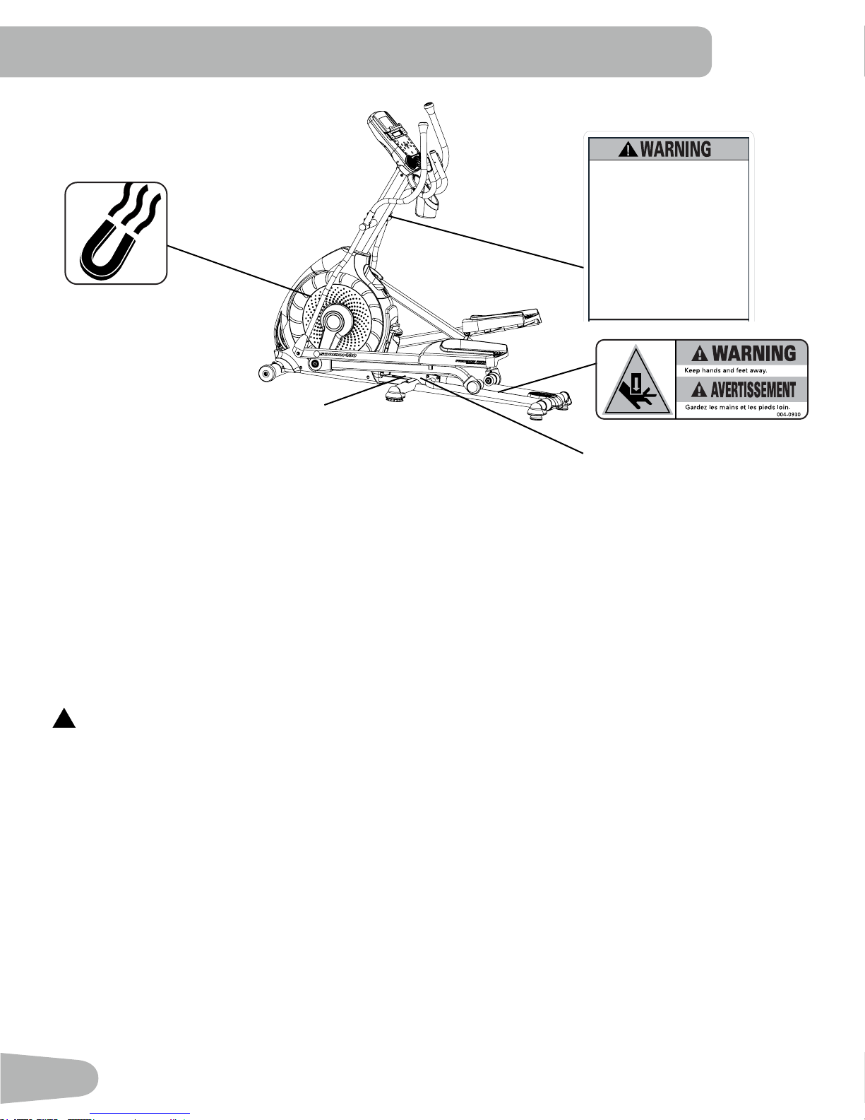
SAFETY WARNING LABELS AND SERIAL
REVISIONS
ECO
REVISION
REV DESCRIPTION
A RELEASED
NPI 13149 DLOVELY
21.78mm
NUMBER
• Read, understand and obey all
warnings on this machine.
• Keep children away.
• Not intended for use by anyone
under 14 years of age.
• Prior to use, read and understand
the Owner ’s Manual.
• Injury or death is possible if
Caution is not used while using this
machine.
• The maximum user weight for this
machine is 300 lbs (136 kg).
• Replace any “Caution”, “Warning”
or “Danger” label that is illegible,
damaged, or removed.
• The heart rate displayed is an
approximation and should be used
for reference only.
•
Serial Number
•
Product Specification
FCC Compliance
Changes or modifications to this unit not expressly approved by the party responsible for compliance could void the
!
user’s authority to operate the equipment.
The machine and power supply comply with part 15 of the FCC rules. Operation is subject to the following two conditions:
(1) This device may not cause harmful interference, and (2) this device must accept any interference received, including
interference that may cause undesired operation.
Note: This machine and power supply have been tested and found to comply with the limits for a Class B digital device,
pursuant to Part 15 of the FCC Rules. These limits are designed to provide reasonable protection against harmful
interference in a residential installation. This equipment generates, uses and can radiate radio frequency energy and, if
not installed and used in accordance with the instructions, may cause harmful interference to radio communications.
However, there is no guarantee that interference will not occur in a particular installation. If this equipment does cause harmful
interference to radio or television reception, which can be determined by turning the equipment off and on, the user is
encouraged to try to correct the interference by one or more of the following measures:
• Reorient or relocate the receiving antenna.
• Increase the separation between the equipment and receiver.
• Connect the equipment into an outlet on a circuit different from that to which the receiver is connected.
• Consult the dealer or an experienced radio/TV technician for help.
4
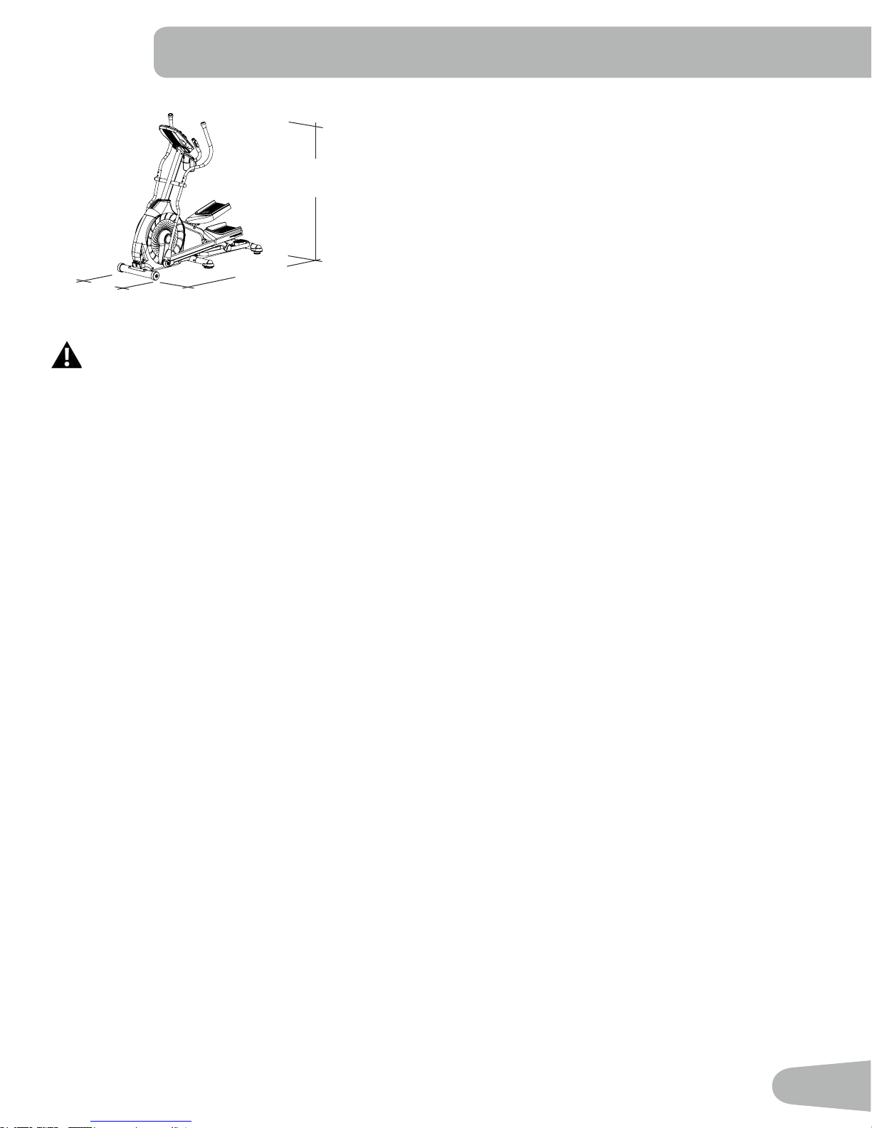
SPECIFICATIONS
Maximum User Weight: 300 lbs. (136 kg)
63.2”
(160.5 cm)
70.1”
28.2”
(71.5 cm)
This product, its packaging, and components contain chemicals known to the State of California to cause cancer,
birthdefects,orreproductiveharm.ThisNoticeisprovidedinaccordancewithCalifornia’sProposition65.Ifyou
wouldlikeadditionalinformation,pleaserefertoourwebsiteatwww.nautilus.com/prop65.
(178.1 cm)
Power Requirements:
Operational Voltage: 9VDC
Operating Current: 1500 mA
Regulatory Approvals:
AC Power Adapter: UL listed, CSA certified (or equivalent),
Rated 120V 60Hz Input, 9VDC, 1500mA
Output. Class 2.
Before Assembly
Select the area where you are going to set up and operate your machine. For safe operation, the location must be on a
hard, level surface. Allow a workout area of a minimum 76.2” x 118.1” (193.4 cm x 300 cm). Be sure that the workout space
you are utilizing has adequate height clearance, taking into consideration the height of the user and the maximum incline of
the elliptical machine.
Basic Assembly Tips
Follow these basic points when you assemble your machine:
• Read and understand the “Important Safety Instructions” before assembly.
• Collect all the pieces necessary for each assembly step.
• Using the recommended wrenches, turn the bolts and nuts to the right (clockwise) to tighten, and the left (counterclockwise) to loosen, unless instructed otherwise.
• When attaching 2 pieces, lightly lift and look through the bolt holes to help insert the bolt through the holes.
• The assembly can require 2 people.
5
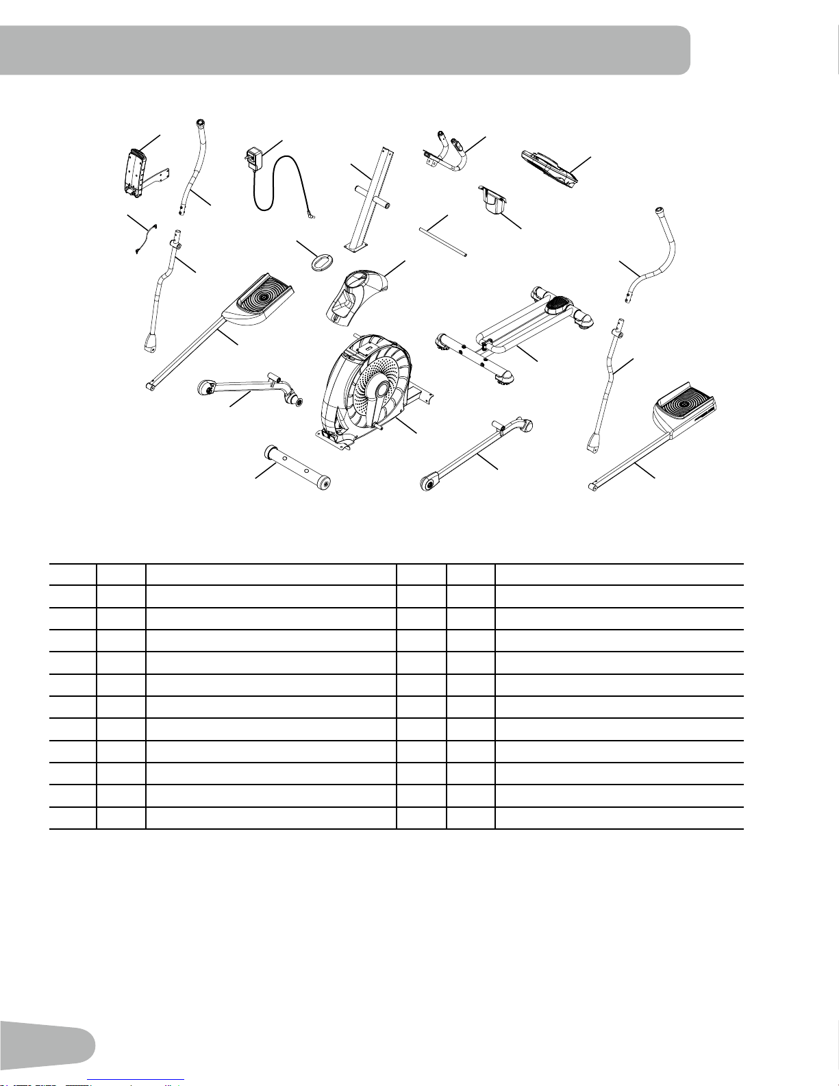
PARTS
20
21
17
18
14
15
13
19
16
2
1
3
4
12
9
11
10
5
6
7
8
A decal has been applied to all right (“ R ”) and left (“ L ”) parts to assist with assembly.
Item Qty Description Item Qty Description
1 1 Console Mast 12 1 Upper Shroud
2 1 Static Handlebar 13 1 Front Stabilizer
3 1 Arm Pivot Rod 14 1 Right Leg
4 1 Water Bottle Holder 15 1 Right Pedal
5 1 Console 16 1 Shroud Cap
6 1 Upper Left Handlebar Arm 17 1 Lower Right Handlebar Arm
7 1 Lower Left Handlebar Arm 18 1 Upper Right Handlebar Arm
8 1 Left Pedal 19 1 AC Adapter
9 1 Rail Assembly 20 1 MP3 Cord
10 1 Left Leg 21 1 Manual Lift Assembly
11 1 Frame
22 1 Silicone Lubricant, Bottle (not shown)
6
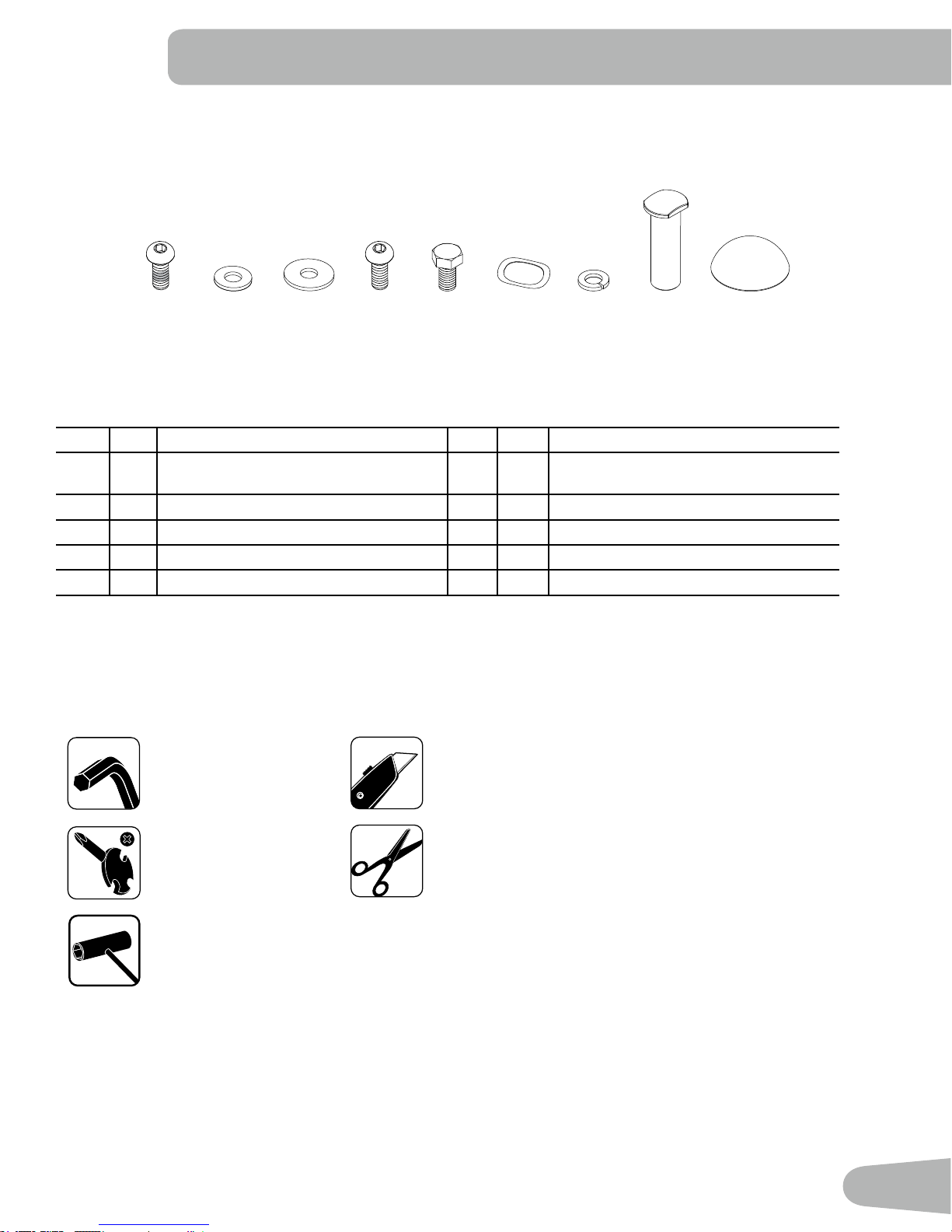
HARDWARE / TOOLS
A B C D E F
Item Qty
A 6 Button Head Hex Screw, M8x16 (with
B 4 Flat Washer, M8 G 12 Lock Washer, M8
C 8 Wide Washer, M8 H 2 Pivot Sleeve
D 4 Button Head Hex Screw, M8x16 I 2 Cap
E 2 Hex Head Screw, M8x20
Description
Loctite
®
adhesive)
Item Qty
F 6 Wave Washer
G H
Description
Tools
Included Not Included
I
6 mm
#2
13 mm
15 mm
19 mm
(recommended)
7
ASSEMBLY
13
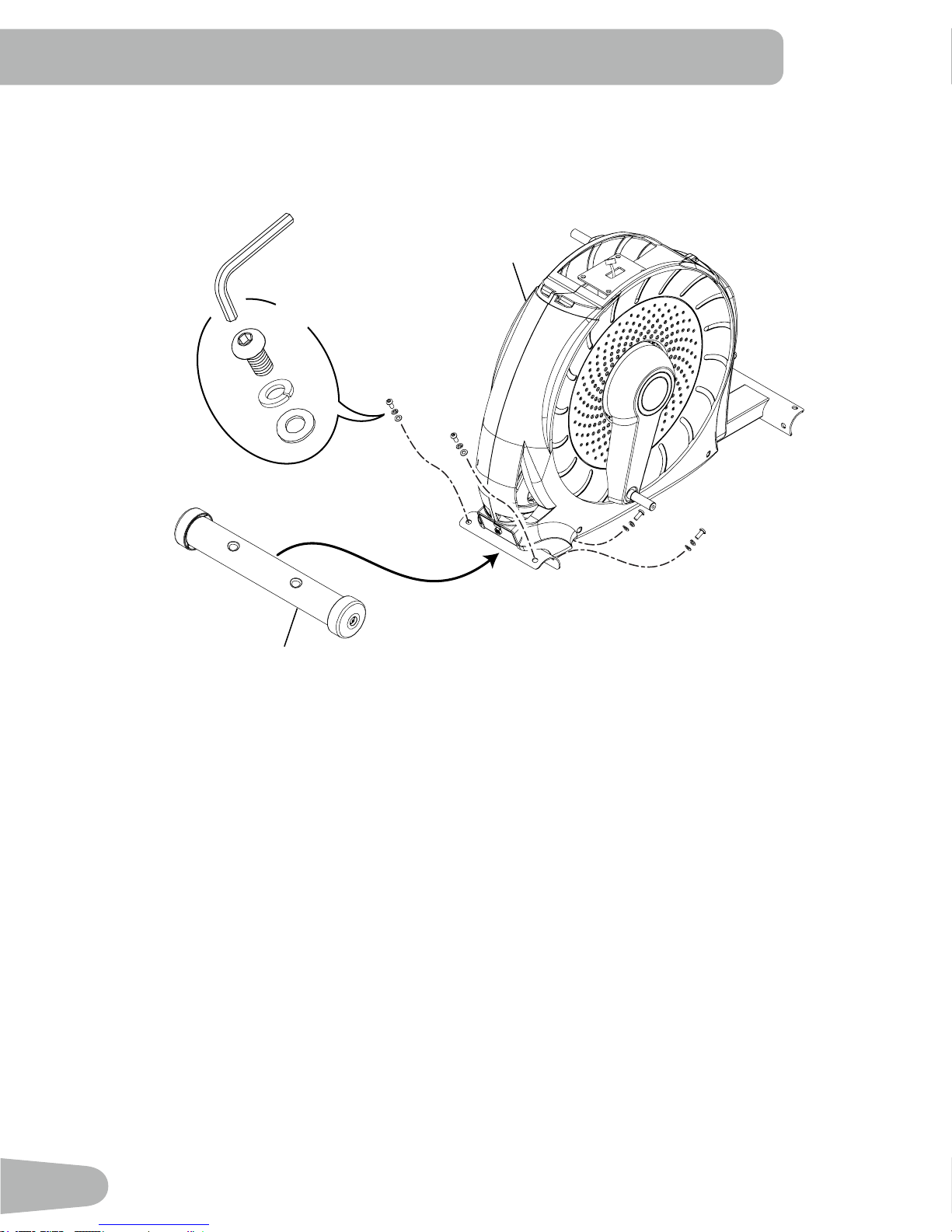
1. Attach Front Stabilizer to Frame
Note: Hardware is pre-installed and not on the Hardware Card. *
11
6mm
X4
*
*
*
8
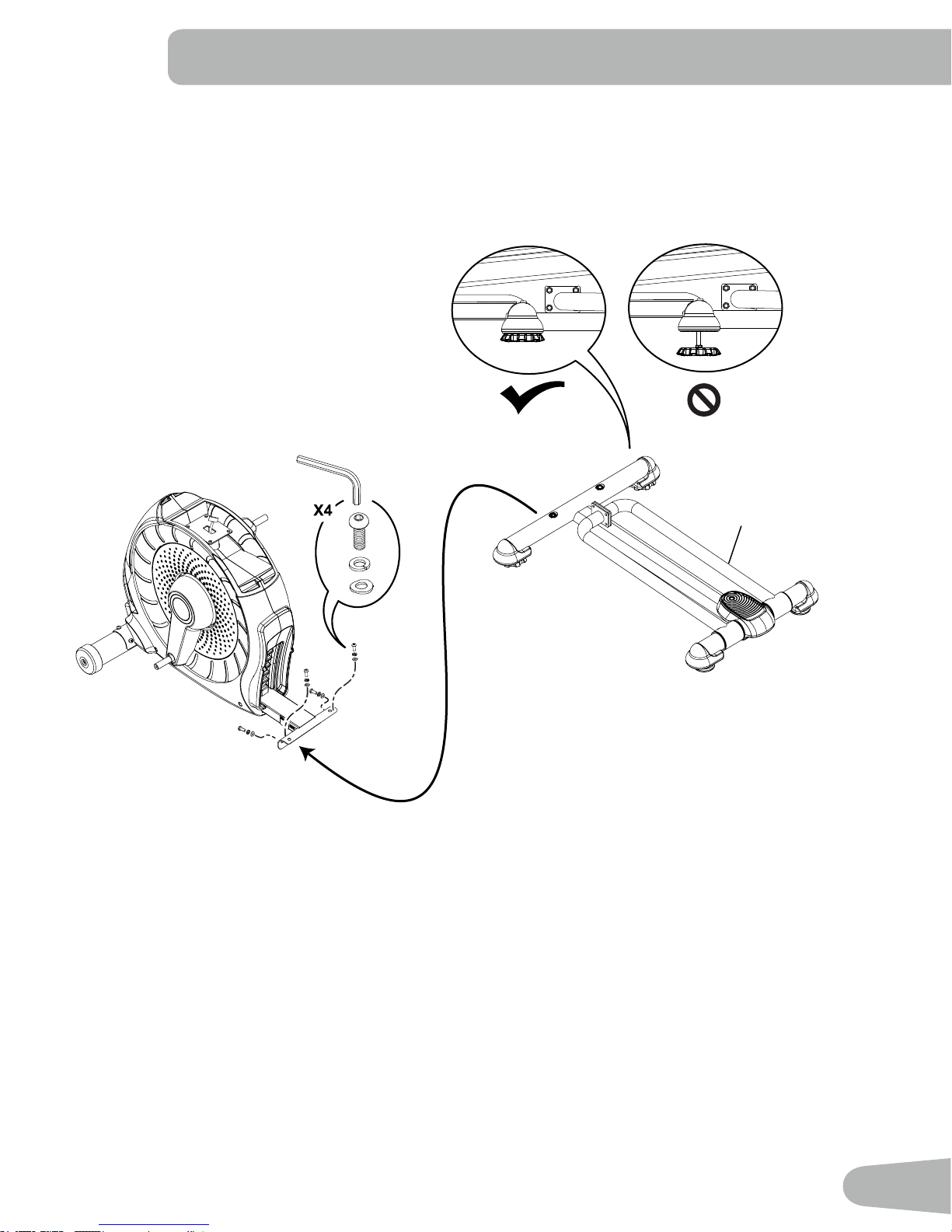
2. Attach Rail Assembly to Frame Assembly
Note: Be sure Levelers are fully raised on Rail Assembly. Hardware is pre-installed and not on the Hardware Card. *
6mm
9
*
*
*
9
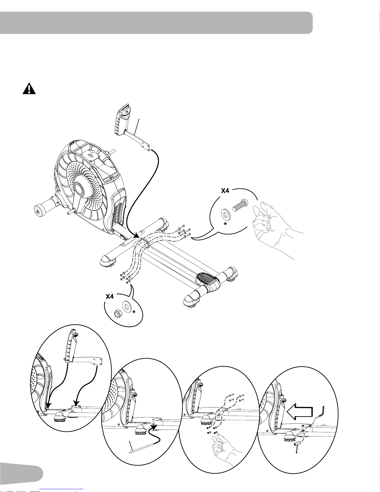
3. Attach the Manual Lift Assembly using the Arm Pivot Rod
Note: Hardware is pre-installed and not on the Hardware Card. *
NOTICE : With the Arm Pivot Rod under the plate junction, push the Manual Lift Assembly toward the Frame Assembly
and fully tighten hardware. Remove the Arm Pivot Rod after tightening.
Keep fingers away from any pinch opportunities when placing or removing the Arm Pivot Rod.
21
*
*
3
10
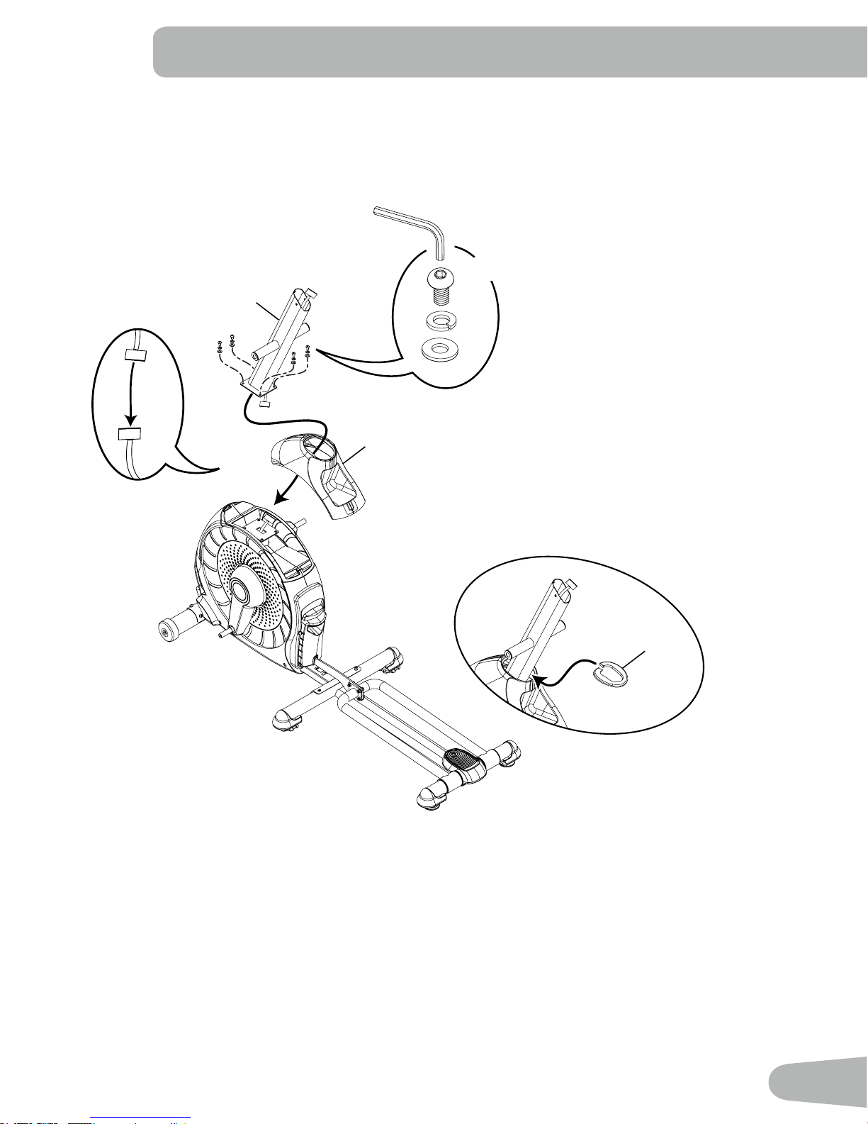
4. Connect the Cable and Attach the Console Mast to Frame Assembly
NOTICE : Do not crimp Console Cable.
6mm
X4
1
12
D
G
B
16
11
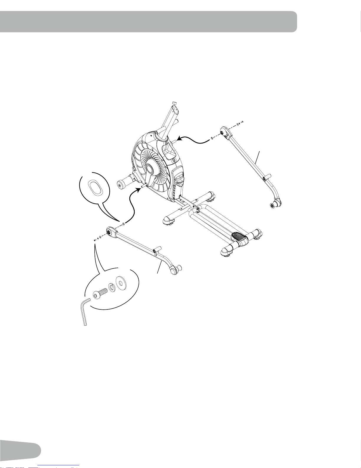
5. Attach Legs to Frame Assembly
X2
F
14
6mm
X2
10
C
G
A
12
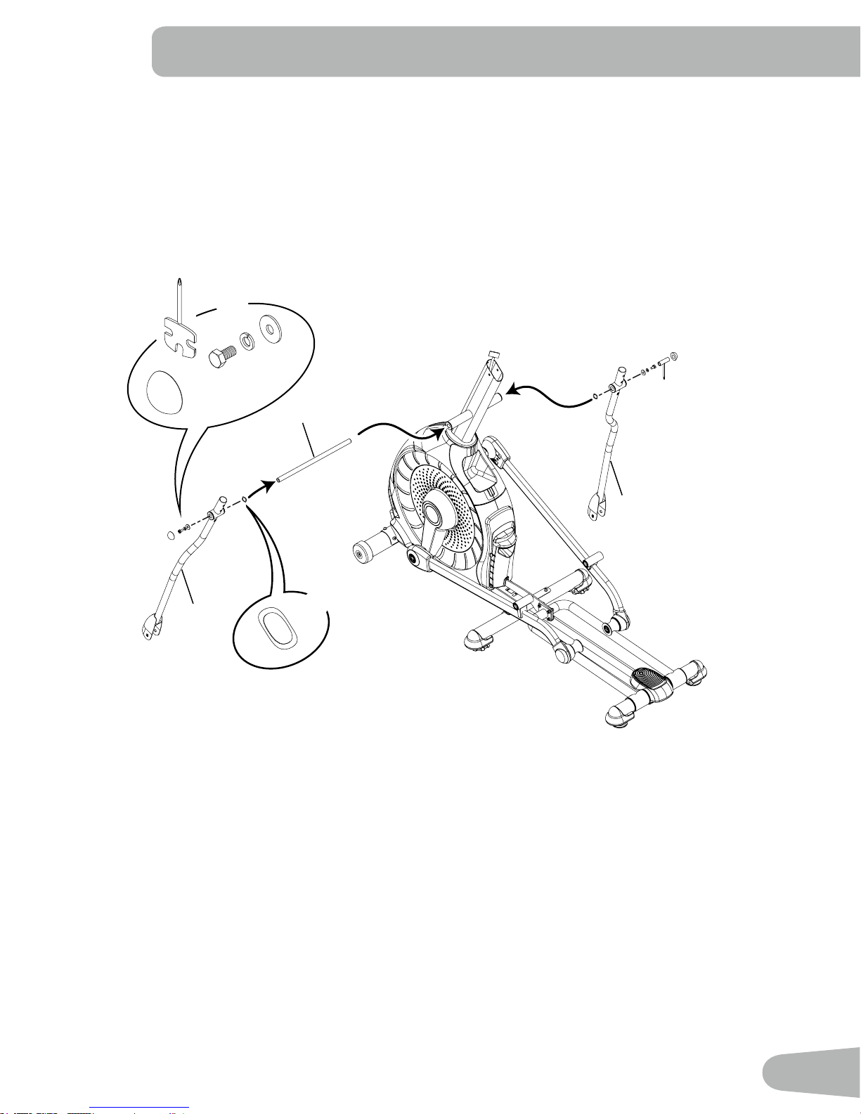
6. Attach Arm Pivot Rod and Lower Handlebar Arms to Frame Assembly
X2
13 mm
C
G
E
I
7
3
17
X2
F
13
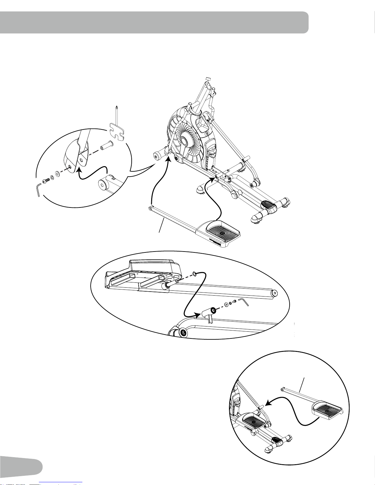
7. Attach Left Pedal to Frame Assembly
A
C
G
F
8
C
H
NOTICE : Repeat step on opposite side with the Right Pedal (Item 15).
H
C
G
A
6mm
8
F
A
G
C
15
14
 Loading...