

Page 1
APPLICATION
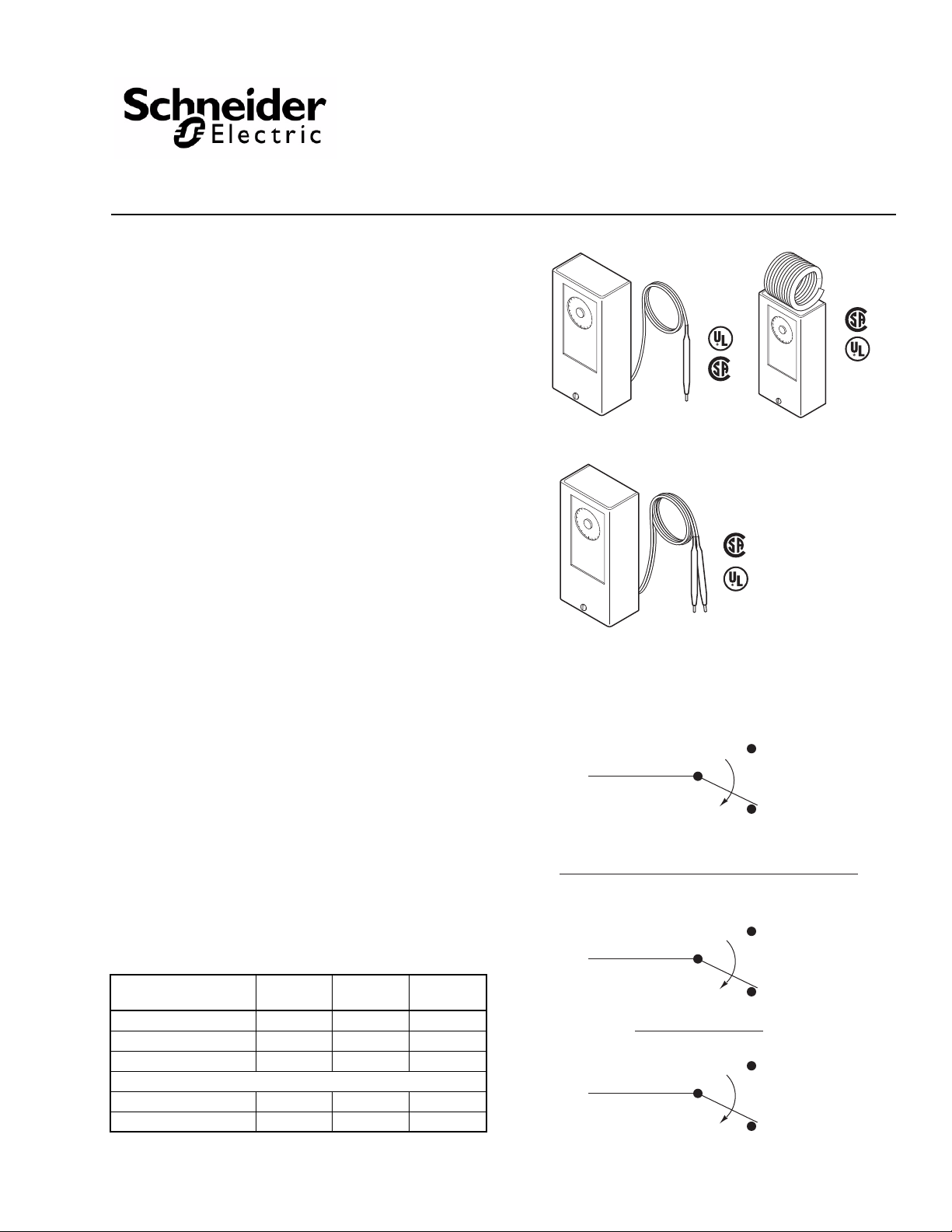
N.O.
N.C.
Temp. Drop
N.O. makes ON temperature drop
Low (N.O.)
Low (N.C.)
1st stage cool
Temp. Drop
Common
Common
High (N.O.)
1st stage Heat
High (N.C.)
Temp. Drop
Typical Two Stage
Typical Single Stage
Common
Low
High
Typical
Single Bulb
Typical
Dual Bulb
For on-off control of media temperature in ducts, tanks, liqui d
lines, etc.
SPECIFICATIONS
Setpoint Dial Range: Dial plate is marked as °F on one
side and °C on the other. See Table-2 for specific ranges.
Sensing Element: Liquid-filled copper. Differential: See Table-2. Dual Bulb Units: One bulb senses the controlled media;
the second bulb senses the outside air temperature. The
temperature of the controlled media increases as outside air
temperature decreases.
Ambient Temperature Limits:
Case,
Shipping -40 to 160°F (-40 to 71°C). Operating -40 to 150°F (-40 to 65°C): except return
air bulb unit, -40 to 140°F (-40 to 60°C).
Bulb, See Table-2. Electrical Switch: Snap action SPDT, one per stage. Ratings, See Table-1. Connections: Coded screw terminals. Cover: All metal with 1/2" to 3/4" conduit openings. Case Locations: NEMA Type 1 indoor only. Mounting: Case can be mounted in any position. See
ACCESSORIES for bulb mounting kits (order separately).
Dimensions:
Case, 4-5/8" high x 2-1/4" wide x 2" deep (117 mm x 57
mm x 51 mm)
Element and Capillary, See Table-2.
ACCESSORIES
AT-201 Copper bulb well requires AT-209
AT-203 Stainless steel bulb well requires AT-209
AT-206 Copper bulb well
AT-208 Duct mounting kit
AT-209 Bulb mounting kit
AT-210 Concealed adjustment plate
AT-211 Outside bulb shield
Table-1 Maximum Electrical Rating
(All units except TC-4115*)
TC-4100 Series, TC-4200
Series
Bulb Thermostats & Return Air Thermostats
General Instructions
Typical
Return Air Bulb
Switch Rating (50/60
Full Load Amps 9.8 9.8 8.0
Locked Rotor Amps 58.8 58.8 48.0
Pilot Duty VA 60 360 360
Non-Inductive Amps (Resistive)
Single Stage 22 22 22
Two Stage 16 16 8.0
* TC-4115 for TAC System 8000 and applications requiring le ss than one (1)
amp. Electrical Rating: 1.0 amp at 24 Vac; 0.25 amp at 24 Vdc.
Hz)
24V 120V 240V
Figure-1 Switch Action and Terminal Identification.
Printed in U.S.A. 11/09 © Copyright 2009 Schneider Electric All Rights Reserved. F-18895-7
Page 2
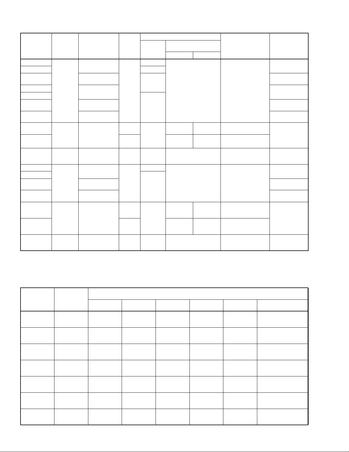
Table-2 Specifications.
Part
Number
Type
TC-4111
TC-4111-020 20 (6)
TC-4112
b
TC-4115
TC-4121
Single Stage
Single Bulb
TC-4122
TC-4123
Setpoint
Adjustment
Range
°F (°C)
-40 to 120
(-40 to 49)
100 to 260
(38 to 127)
-40 to 120
(-40 to 49)
100 to 260
(38 to 127)
190 to 350
(88 to 176)
TC-4151
Single Stage
TC-4152 1:1
Dual Bulb
Single Stage
TC-4166
Return Air
Bulb
TC-4211
TC-4221
TC-4222
Two Stage
Single Bulb
TC-4223
70 to 120
(21 to 49)
50 to 90
(10 to 32)
-40 to 120
(-40 to 49)
100 to 260
(38 to 127)
190 to 350
(88 to 176)
TC-4251
Two Stage
Dual Bulb
70 to 120
(21 to 49)
Dual
Bulb
Ratio
1:1-1/2
1:1-1/2
a
c
c
Capillary
Copper
ft. (m)
6 (1.8)
6 (1.8)
10 (3)
Armored
30 (9)
Each Bulb
None
6 (1.8)
10 (3)
Armored
30 (9)
Each Bulb
TC-4252 1:1
TC-4266
a
First number of reset ratio typically indicates outdoor air temperature change required to increase the setpoint by the second number.
b
See Electrical Rating.
c
For 1-1/2:1 ratio, reverse bulbs and use extra dial supplied with unit.
Return Air
Bulb
Two Stage
50 to 90
(10 to 32)
None
Dimensions
Bulb Copper
in. (mm)
Indoor Outdoor
3/8 x 4
(9.5 x 10²)
3/8 x 4
(9.5 x 10²)
3/8 x 4
(9.5 x 10²)
2-1/2 x 2 (64 x 51)
3/8 x 4
(9.5 x 10²)
3/8 x 4
(9.5 x 10²)
2-1/2 x 2 (64 x 51)
3/8 x 5-1/2
(9.5 x 140)
(9.5 x 10²)
Coiled
3/8 x 4
(9.5 x 10²)
3/8 x 5-1/2
(9.5 x 140)
(9.5 x 10²)
Coiled
3/8 x 4
3/8 x 4
Differential
°F (°C)
Factory Set 3 (2)
Adj. 3 to 16 (2 to 9)
Factory Set 3 (2)
Adj. 1-1/2 to 10 (1 to 5)
Factory Set 3 (2)
Adj. 3 to 16 (2 to 9)
Fixed 2 (1)
Per Stage Fixed 3 (2)
Between Stages Set 3 (2)
Adj. 2 to 10 (1 to 5)
Per Stage Fixed 3 (2)
Between Stages Set 3 (2)
Adj. 1.5 to 6.5 (1 to 4)
Per Stage Fixed 3 (2)
Between Stages Set 3 (2)
Adj. 2 to 10 (1 to 5)
Each Stage Fixed 2 (1)
Between Stages Set 3 (2)
Adj. 1 to 5 (0.5 to 3)
Safe Bulb
Temperature
Range
°F (°C)
-40 to 170
(-40 to 77)
-40 to 310
(-40 to 154)
-40 to 170
(-40 to 77)
-40 to -310
(-40 to 154)
-40 to 400
(-40 to 204)
Total of indoor and
outdoor
temperatures
must not exceed
280 (138)
-40 to 145
(-40 to 63)
-40 to 170
(-40 to 77)
-40 to 310
(-40 to 154)
-40 to 400
(-40 to 204)
Total of indoor and
outdoor
temperatures
must not exceed
280 (138)
-40 to 145
(-40 to 63)
Table-3 Ratio Selection Table.
Outdoor
Temperature
in °F
-30
-20
-10
0
+10
+20
+30
Ratio
1 to 1-1/2
1 to 1
1-1/2 to 1
1 to 1-1/2
1 to 1
1-1/2 to 1
1 to 1-1/2
1 to 1
1-1/2 to 1
1 to 1-1/2
1 to 1
1-1/2 to 1
1 to 1-1/2
1 to 1
1-1/2 to 1
1 to 1-1/2
1 to 1
1-1/2 to 1
1 to 1-1/2
1 to 1
1-1/2 to 1
Dial Set at 70°F Dial Set at 80°F Dial Set at 90°F
70 to 220
70 to 170
70 to 137
70 to 205
70 to 160
70 to 130
70 to 190
70 to 150
70 to 123
70 to 175
70 to 140
70 to 117
70 to 160
70 to 130
70 to 110
70 to 145
70 to 120
70 to 103
70 to 130
70 to 110
70 to 97
80 to 230
80 to 180
80 to 147
80 to 215
80 to 170
80 to 140
80 to 200
80 to 160
80 to 133
80 to 185
80 to 150
80 to 127
80 to 170
80 to 140
80 to 120
80 to 155
80 to 130
80 to 113
80 to 140
80 to 120
80 to 107
Change in Water Temperature for Different Ratios as
Outdoor Temperature Drops from 70°F to Design Temperature
90 to 240
90 to 190
90 to 157
90 to 225
90 to 180
90 to 150
90 to 210
90 to 170
90 to 143
90 to 195
90 to 160
90 to 137
90 to 180
90 to 150
90 to 130
90 to 165
90 to 140
90 to 123
90 to 150
90 to 130
90 to 117
Dial Set at
100°F
100 to 250
100 to 200
100 to 167
100 to 235
100 to 190
100 to 160
100 to 220
100 to 180
100 to 153
100 to 205
100 to 170
100 to 147
100 to 190
100 to 160
100 to 140
100 to 175
100 to 150
100 to 133
100 to 160
100 to 140
100 to 127
Dial Set at
110°F
110 to 260
110 to 210
—
110 to 245
110 to 200
—
110 to 230
110 to 190
—
110 to 215
110 to 180
—
110 to 200
110 to 170
—
110 to 185
110 to 160
—
110 to 170
100 to 150
—
Dial Set at 120°F
120 to 270
120 to 220
—
120 to 255
120 to 210
—
120 to 240
120 to 200
—
120 to 225
120 to 190
—
120 to 210
120 to 180
—
120 to 195
120 to 170
—
120 to 180
120 to 160
—
°C = (°F - 32) 5/9.
2 © Copyright 2009 Schneider Electric All Rights Reserved. F-18895-7
Page 3
DUAL BULB SELECTION
On the dual bulb units, indoor and outdoor bulbs are
determined by the ratio selected (see T able-2). Ratio refers to
the outdoor air temperature change compared to the water
temperature change. The dial setpoint is the water
temperature setpoint when the outdoor temperature is 70°F.
T o select ratio, it is necessary to know only: (1) outdoor design
temperature, (2) maximum water temperature at outdoor
design temperature, and (3) desired water temperature at
70°F outdoors. Use Table-3 to determine the required ratio
based on this information and set the dial per item (3).
Note: If a 1-1/2:1 ratio is selected, the extra di al sup p l ied
with the unit must be used.
Example: Select ratio for an installation with a -10°F design
temperature and estimated supply water temperature of 75°F
at 70°F outdoors and 125°F at -10°F outdoors. From Table-3,
-10°F for 1-1/2:1 ratio, note by interpolation (70°F to 123°F
with dial at 70°F, 80°F to 133°F with dial at 80°F) that water
temperature varies from 75°F to 128°F as outdoor
temperature drops from 70°F to -10°F.
For this application, the 1-1/2:1 ratio should be selected. The
extra dial supplied with the unit would be used, and the dial set
at 75°F.
PRE-INSTALLATION
Location
Locate the device allowing proper distance to the bulb
location. The case can be mounted in any position. Refer to
Figure-2 for case dimensions.
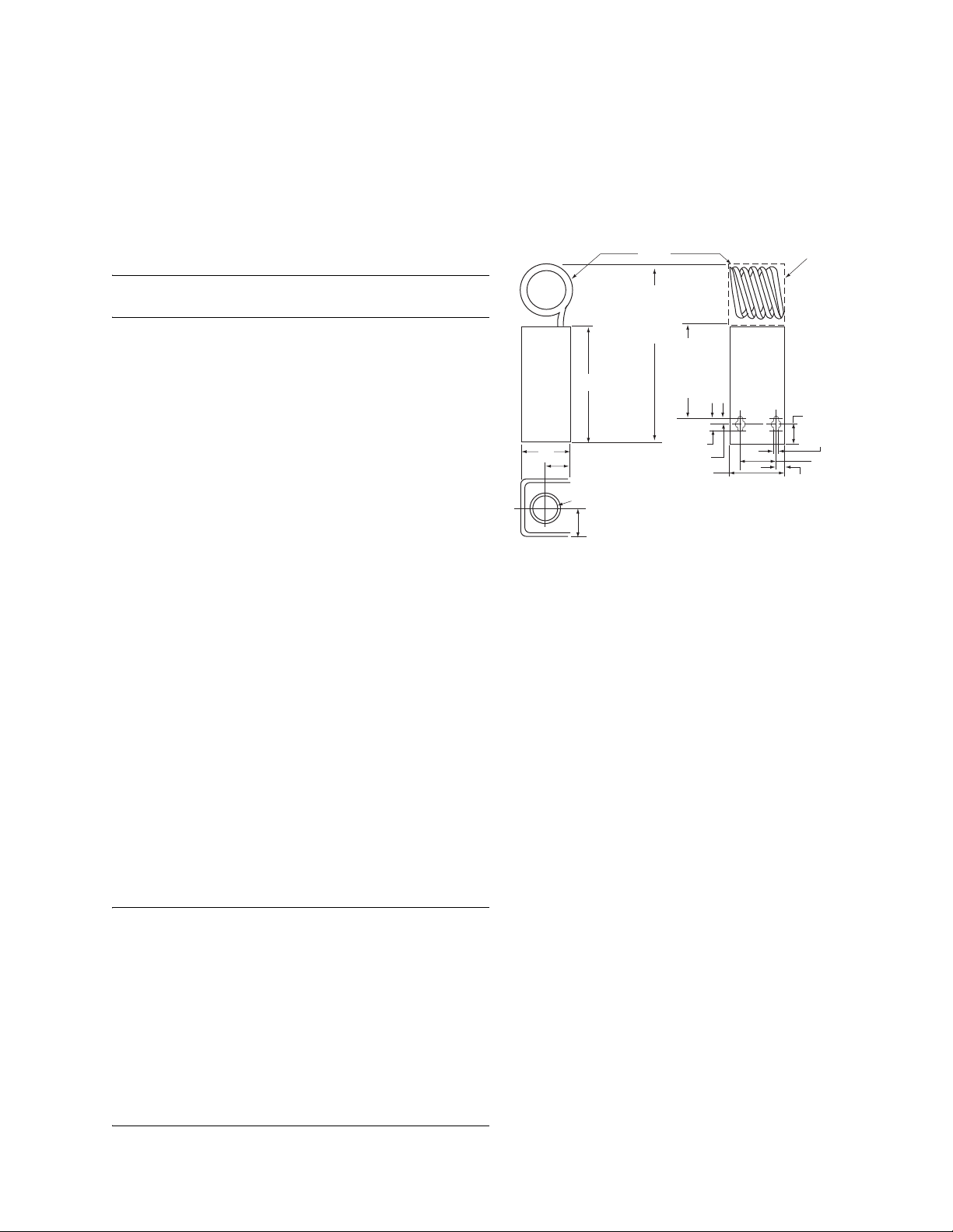
TC-4166
TC-4266
Only
Cut Hole in
Duct 2-1/4" W x
2-1/2" H for
Mounting in
Return Air
7/8"
13-64"
1-9/16"
Side
2"
Bottom
TC-4166
TC-4266
Only
7"
TC-4166
TC-4266
Only
3-5/8"
TC-4166
4-5/8"
1"
Hole for 1/2" Conduit
Knockout for 3/4" Conduit
1-5/64"
TC-4266
Only
1/2"
1/4"
2-1/4"
Back
5/16"
Inspection
Visually inspect the carton for damage. If damaged, notify the
appropriate carrier immediately. If undamaged, open the
carton and visually inspect the device for obvious defects.
Return damaged or defective products.
Required Installation Items
• Wiring diagram
• Tools (not provided):
Volt-ohm meter
Room temperature thermometer on °F or °C
Appropriate screwdriver(s) for cover, terminals and
mounting screws
Appropriate drill and drill bit for mounting screws
INSTALLATION
Caution:
1. Installer must be a qualified, experienced technician.
2. Disconnect power supply before installation to prevent electrical shock and equipment damage.
3. Make all connections in accordance with the electrical wiring diagrams, and in compliance with national and local codes. Use copper conductors only.
4. Do not exceed ratings of the device.
5. Avoid locations where excessive moisture, corrosive fumes or vibrations are present.
Figure-2 Case Dimensions.
Procedure for Remote Bulb Mounting
Air Bulb Models — Mounting in Return Air Duct
1. Remove cover and provide two holes for #10 round head screws using the housing as the template or by using the dimensions shown in Figure-2.
2. Partially insert the mounting screws in the screw holes. Fit the housing over the screws, slide housing down on the screws and tighten the screws.
Air Bulb Models —
Mounting Outside of Return Air Duct
1. Prepare duct for mounting by cutting hole and providing mounting screw holes per Figure-2.
2. Fabricate a cover as shown in Figure-3.
3. Carefully roll bulbs toward back of unit and insert through 2-1/4" x 2-1/2" (57 mm x 64 mm) hole.
4. Remove cover and attach unit to duct with #10 screws.
5. Attach cover over 2-1/4" x 2-1/2" (57 mm x 64 mm) hole.
F-18895-7 © Copyright 2009 Schneider Electric All Rights Reserved. 3
Page 4

Figure-3 Field Supplied Duct Hole Cover Plate.
Duct and Outdoor Mounting
Maximum insertion length is 6 inches.
Duct: Install bulb with AT-208 kit as shown in Figure-4.
Figure-7 AT-201 or AT-203 Installation.
AT-201 or AT-203 Installation (see Figures-6 and 7):
1. Install bulb well or adaptor from A T-209 into 3/4" FNPT opening.
2. Place packing nut, washers and packing from AT -209 over bulb support section and insert bulb well or AT-209 adaptor.
3. Push interlocking washers and packing into well or adaptor and tighten packing nut until firmly sealed.
Figure-4 Duct Mounting with AT-208.
Outdoor: Install with AT-211 kit as shown in Figure-5.
1. Mount bulb to outside wall or surface with bulb clip.
2. Place shield over bulb and fasten to mounting surface.
Figure-5 Outdoor Mounting with AT-211.
Bulb Mounting — Liquid Line and Tank
Figure-8 AT-206 Installation.
AT-206 Installation (see Figures-6 and 8):
1. Install AT-206 bulb well into 1/2" FNPT opening.
2. Place packing (included with AT-206) over bulb support section and insert bulb into well.
3. Push packing into nut on well using a screwdriver.
Concealed Setpoint and Lock Cover Screw
Order AT-210 concealed adjustment kit separately.
1. Peel off adhesive film from the concealed adjustment plate and place into the recess of cover.
2. Remove screw from cover.
3. Install lock cover screw provided with AT-210.
Figure-6 Bulb Mounting for Liquid Line and Tank.
4 © Copyright 2009 Schneider Electric All Rights Reserved. F-18895-7
Page 5

Table-4 Bulb Mounting Installation Hardware And Application Limitations.
Application Limitations
Part
Number
AT-201
AT-203
AT-206
a
Max. recommended fluid temperature is 350 F (177°C).
b
Requires AT-209.
b
b
Description
Copper
Bulb Well
Stainless Steel
Bulb Well
Copper
Bulb Well
Mounting
Fitting
3/4"
MNPT
1/2"
MNPT
Insertion Size
in. (mm)
1/2 (13) dia. O.D.
9-1/2 (241) long
1/2 (13) dia. O.D.
4-1/2 (114) long
at 250°F (121°C) Fluid Temperature
Max. Recommended
Velocity fps (m/s)
11 (3.3) 250 (1728)
20 (6.1) 500 (3448)
11 (3.3) 250 (1728) 8
WIRING
The thermostat has one 1/2" to 3/4" conduit opening in the
bottom of the housing. Terminal coding and switch action are
shown in Figures-9 and 10.
a
Max. Recommended
Static Press. psig (kPa)
Installation
per Figure
7
Figure-9 Terminal Coding and Switch Action.
Figure-10 Two Stage Switch Sequence.
TYPICAL APPLICATIONS
Figures-11 and 12 show typical heating and cooling
applications for single stage units. Figures-13 and 14 show
typical heating and cooling applications for two stage units.
Figure-11 Typical Heating Application for Single Stage Units.
Figure-12 Typical Cooling Application for Single Stage Units.
Figure-13 Typical Heating Application for Two Stage Units.
F-18895-7 © Copyright 2009 Schneider Electric All Rights Reserved. 5
Page 6

Figure-14 Typical Cooling Application for Two Stage Units.
CHECKOUT
After installing a thermostat, make an initial check of the
switching action. Verify the switch action by listening to the
switch contacts.
1. Turn the setpoint dial to a tempera ture above ambient. This should cause the thermostat to switch, making orange to brown.
2. Turn the setpoint dial setting down gradually. Orange to brown must break, making orange to red.
3. Compare the differential of the device to the differential
shown on the performance charts by turning the dial. The
differential of the device is the difference in dial reading
between the make of orange to brown and the make of
orange to red on single switch units.
ADJUSTMENTS
To adjust interstage differential:
1. Disconnect power to unit.
2. Remove cover.
3. Turn adjustor to approximately desired position.
4. Check out by turning dial and noting dial readings where switch contacts make.
5. After changing interstage differential, recalibrate. See CALIBRATION.
CALIBRATION
1. With all power disconnected, soak bulb(s) for 10 minutes at known temperature (must be 70°F for dual bulb).
2. Turn dial and note where switch contacts make.
3. Turn dial midway between click points.
4. Turn the calibration nut (located under dial) until the temperature of the bulb is indicated on the dial (see Figure-15).
Note: On two stage units follow above procedure. LO switch
is first stage on cooling applications. HI switch is first stage on
heating applications.
MAINTENANCE
Regular maintenance of the total system is needed to assure
sustained optimum performance. Thermostats should be
periodically inspected for dirt or blockage of air over the
elements.
Setpoint
Screwdriver adjustment. Scales dual marked °F on front and
°C on back. To change scale, remove spring retaining ring,
select scale and replace retaining ring.
Differential
The differential is adjustable by turning the adjustor located on
the side of the device (see Figure-15).
Calibration Nut
(Turn with 1/2"
open end wrench)
Incr. Spread
Differential Adjustment
Figure-15 Adjustments.
Single Stage: Each line represents approximately 3°F (2°C)
change.
Two Stage: Each notch represents approximately 2°F (1°C)
change between stages. (Differential per switch is fixed.)
REPAIR
Field repair is not recommended. Replace defective device.
6 © Copyright 2009 Schneider Electric All Rights Reserved. F-18895-7
Page 7

F-18895-7 © Copyright 2009 Schneider Electric All Rights Reserved 7
Page 8

On October 1st, 2009, TAC became the Buildings business of it s parent company Schneide r Electric. This document reflects th e visual identity of Schneider Ele ctric,
however there remains references to T AC as a corporate brand in th e body copy. As each document is updated, the body copy will be changed to reflect ap propriate
corporate brand changes.
Copyright 2009, Schneider Electric
All brand names, trademarks and registered
trademarks are the property of their respective
owners. Information contained within this
document is subject to change without notice.
F-18895-7
 Loading...