


Modicon X80
Discrete Input/Output Modules
User Manual
Original instructions
11/2020
35012474.18
www.se.com

Legal Information
The Schneider Electric brand and any trademarks of Schneider Electric SE and its
subsidiaries referred to in this guide are the property of Schneider Electric SE or its
subsidiaries. All other brands may be trademarks of their respective owners.
This guide and its content are protected under applicable copyright laws and furnished for
informational use only. No part of this guide may be reproduced or transmitted in any form or
by any means (electronic, mechanical, photocopying, recording, or otherwise), for any
purpose, without the prior written permission of Schneider Electric.
Schneider Electric does not grant any right or license for commercial use of the guide or its
content, except for a non-exclusive and personal license to consult it on an "as is" basis.
Schneider Electric products and equipment should be installed, operated, serviced, and
maintained only by qualified personnel.
As standards, specifications, and designs change from time to time, information contained in
this guide may be subject to change without notice.
To the extent permitted by applicable law, no responsibility or liability is assumed by
Schneider Electric and its subsidiaries for any errors or omissions in the informational
content of this material or consequences arising out of or resulting from the use of the
information contained herein.

Discrete Input/Output Modules
Table of Contents
Safety Information.................................................................................................. 11
Before You Begin..............................................................................................12
Start-up and Test ..............................................................................................13
Operation and Adjustments...............................................................................14
About the Book ...................................................................................................... 15
Hardware Installation of the Discrete I/O Modules ...........................................17
General Introduction...............................................................................................18
General Description of the Modules ................................................................... 18
Physical Description of Discrete Modules with 20-pin Terminal Block
Connection ...................................................................................................... 19
Physical Description of Discrete Modules with 40-pin Terminal Block
Connection ...................................................................................................... 21
Physical Description of Discrete Modules with 40-Pin Connectors ........................22
Discrete Input Modules Catalog ......................................................................... 23
Discrete Output Modules Catalog ...................................................................... 26
Discrete Mixed Input/Output Modules Catalog .................................................... 29
Dimensions of X80 Discrete I/O Modules............................................................ 31
Temperature Derating .......................................................................................34
Standards and Certifications.............................................................................. 36
General Rules for Installing the Modules ................................................................. 37
Fitting of the Modules........................................................................................ 37
20-pin Terminal Blocks: BMX FTB 20•0 .............................................................. 40
40-pin Terminal Blocks: BMX FTB 40•0 .............................................................. 43
BMX FTW ••1 Cable .........................................................................................49
BMX FTW ••5 Cable .........................................................................................53
Fitting a 20-pin Terminal Block to a Module.........................................................57
Fitting a 40-Pin Terminal Block to a Module.........................................................62
Fitting a 40-pin FCN Type Connector to a Module ...............................................67
Presentation for Choosing Power Supplies for Sensors and Pre-Actuators............68
Wiring Precautions ...........................................................................................72
How to Connect Discrete Input/Output Modules: Connecting 40-Pin Connector
Modules...........................................................................................................76
35012474.18 3

Discrete Input/Output Modules
How to Connect Discrete Input/Output Modules: Connecting 40-Pin Connector
Modules to TELEFAST Interfaces ......................................................................82
Sensor/Input Compatibility and Pre-actuator/Output Compatibility ........................ 87
Discrete Input/Output Module Diagnostic Processing ...............................................91
General Protective Measures ............................................................................91
Module and Channel Status Display...................................................................92
Diagnostics ......................................................................................................96
Checking the Connection ..................................................................................99
BMX DDI 1602 Input Modules .............................................................................. 102
Introduction.................................................................................................... 102
Characteristics ............................................................................................... 103
Connecting the Module ................................................................................... 105
BMX DDI 1603 Input Modules .............................................................................. 109
Introduction.................................................................................................... 109
Characteristics ............................................................................................... 110
Connecting the Module ................................................................................... 112
BMX DDI 1604T Input Modules ............................................................................ 116
Introduction.................................................................................................... 116
Characteristics ............................................................................................... 117
Connecting the Module ................................................................................... 120
BMX DDI 3203 Input Modules ............................................................................... 124
Introduction.................................................................................................... 124
Characteristics ............................................................................................... 125
Connecting the Module ................................................................................... 127
BMX DDI 3232 Input Modules ............................................................................... 131
Introduction.................................................................................................... 131
Characteristics ............................................................................................... 132
Connecting the Module ................................................................................... 134
BMX DAI 1602 Input Modules ...............................................................................139
Introduction.................................................................................................... 139
Characteristics ............................................................................................... 140
Connecting the Module ................................................................................... 142
BMX DAI 1603 Input Modules ...............................................................................147
Introduction.................................................................................................... 147
Characteristics ............................................................................................... 148
4 35012474.18

Discrete Input/Output Modules
Connecting the Module ................................................................................... 150
BMX DAI 1604 Input Modules ...............................................................................153
Introduction.................................................................................................... 153
Characteristics ............................................................................................... 154
Connecting the Module ................................................................................... 156
BMX DAI 1614 / BMX DAI 16142 Input Modules ....................................................159
Introduction.................................................................................................... 159
Characteristics ............................................................................................... 160
Connecting the Module ................................................................................... 164
BMX DAI 1615 Input Modules ...............................................................................169
Introduction.................................................................................................... 169
Characteristics ............................................................................................... 170
Connecting the Module ................................................................................... 172
BMX DAI 0805 Input Modules ...............................................................................177
Introduction.................................................................................................... 177
Characteristics ............................................................................................... 178
Connecting the Module ................................................................................... 180
BMX DAI 0814 Input Module ................................................................................ 183
Introduction.................................................................................................... 183
Characteristics ............................................................................................... 184
Connecting the Module ................................................................................... 185
BMX DDI 3202 K Input Modules ........................................................................... 188
Introduction.................................................................................................... 188
Characteristics ............................................................................................... 189
Connecting the Module ................................................................................... 191
BMX DDI 6402 K Input Modules ........................................................................... 195
Introduction.................................................................................................... 195
Characteristics ............................................................................................... 196
Connecting the Module ................................................................................... 198
BMX DDO 1602 Static Output Modules .................................................................202
Introduction.................................................................................................... 202
Characteristics ............................................................................................... 203
Connecting the Module ................................................................................... 205
BMX DDO 1612 Static Output Modules .................................................................208
Introduction.................................................................................................... 208
35012474.18 5

Discrete Input/Output Modules
Characteristics ............................................................................................... 209
Connecting the Module ................................................................................... 211
BMX DRA 0804T Relay Output Modules ............................................................... 214
Introduction.................................................................................................... 214
Characteristics ............................................................................................... 215
Connecting the Module ................................................................................... 216
BMX DRA 0805 Relay Output Modules ................................................................. 219
Introduction.................................................................................................... 219
Characteristics ............................................................................................... 220
Connecting the Module ................................................................................... 222
BMX DRA 0815 Relay Output Modules ................................................................. 225
Introduction.................................................................................................... 225
Characteristics ............................................................................................... 226
Connecting the Module ................................................................................... 229
BMX DRA 1605 Relay Output Modules.................................................................. 232
Introduction.................................................................................................... 232
Characteristics ............................................................................................... 233
Connecting the Module ................................................................................... 235
BMX DRC 0805 Relay Output Modules .................................................................238
Introduction.................................................................................................... 238
Characteristics ............................................................................................... 239
Connecting the Module ................................................................................... 242
BMX DDO 3202 K Static Output Modules...............................................................245
Introduction.................................................................................................... 245
Characteristics ............................................................................................... 246
Connecting the Module ................................................................................... 248
BMX DDO 6402 K Static Output Modules .............................................................. 251
Introduction.................................................................................................... 251
Characteristics ............................................................................................... 252
Connecting the Module ................................................................................... 254
BMX DAO 1605 Triac Output Modules ................................................................... 257
Introduction.................................................................................................... 257
Characteristics ............................................................................................... 258
Connecting the Module ................................................................................... 260
BMX DAO 1615 Isolated Triac Output Modules ...................................................... 263
6 35012474.18

Discrete Input/Output Modules
Introduction.................................................................................................... 263
Characteristics ............................................................................................... 264
Connecting the Module ................................................................................... 267
BMX DDM 16022 Mixed Static Input/Output Module ...............................................271
Introduction.................................................................................................... 271
Characteristics ............................................................................................... 272
Connecting the Module ................................................................................... 276
BMX DDM 16025 Mixed Relay Input/Output module .............................................. 281
Introduction.................................................................................................... 281
Characteristics ............................................................................................... 282
Connecting the Module ................................................................................... 286
BMX DDM 3202 K Mixed Static Input/Output Module .............................................290
Introduction.................................................................................................... 290
Characteristics ............................................................................................... 291
Connecting the Module ................................................................................... 294
TELEFAST 2 Connection Interface Links for the Discrete I/O Modules .....................298
Introduction to the TELEFAST 2 Connection Interfaces for Discrete I/O .............. 298
General Overview of TELEFAST 2 Connection Interfaces for Discrete I/O
Modules ................................................................................................... 299
TELEFAST 2 Connection Bases Catalog .................................................... 299
Combination of Discrete I/O Modules and TELEFAST 2 Connection
Bases ...................................................................................................... 306
Connection Principles for the TELEFAST 2 Interfaces for Discrete I/O ................ 307
Connecting a Discrete Input/Output Module to a TELEFAST 2 Base
Interface................................................................................................... 307
Dimensions and Mounting of the TELEFAST 2 Connection Bases ................ 309
TELEFAST 2 ABE-7H08R10/08R11 and ABE-7H16R10/16R11 Connection
Bases ............................................................................................................ 313
Sensor and Pre-actuator Connections on the ABE-7H08R10/R11 and
ABE-7H16R10/R11 Bases......................................................................... 313
TELEFAST 2 ABE-7H12R10/12R11 Connection Bases.....................................314
Sensor and Pre-actuator Connections on the ABE-7H12R10/R11
Bases ...................................................................................................... 314
TELEFAST 2 ABE-7H08R21 and ABE-7H16R20/16R21/16R23 Connection
Bases ............................................................................................................ 316
35012474.18 7

Discrete Input/Output Modules
Sensor and Pre-actuator Connections on the ABE-7H08R21 and ABE-
7H16R20/R21/R23 Bases for Type 2 Inputs................................................ 316
TELEFAST 2 ABE-7H12R20/12R21 Connection Bases..................................... 318
Sensor and Pre-actuator Connections on the ABE-7H12R20/12R21
Bases ...................................................................................................... 318
TELEFAST 2 ABE-7H08S21/16S21 Connection Bases ..................................... 319
Sensor and Pre-actuator Connections on ABE-7H08S21/16S21 Bases with
One Isolator per Channel...........................................................................320
TELEFAST 2 ABE-7H12S21 Connection Base .................................................321
Sensor and Pre-actuator Connections on the ABE-7H12S21 Base with 1
Isolator per Channel..................................................................................322
TELEFAST 2 ABE-7H16R30/16R31 Connection Bases..................................... 323
Sensor and Pre-actuator Connections on the ABE-7H16R30/R31
Bases ...................................................................................................... 324
TELEFAST 2 ABE-7H12R50 Connection Base .................................................325
Sensor and Pre-actuator Connections on the ABE-7H12R50 Bases ............. 326
TELEFAST 2 ABE-7H16R50 Connection Base .................................................327
Sensor and Actuator Connections on the ABE-7H16R50 Base..................... 327
TELEFAST 2 ABE-7H16F43 Connection Base ................................................. 329
Actuator Connections on ABE-7H16F43 Output Base with One Fuse and
One isolator per Channel........................................................................... 329
TELEFAST 2 ABE-7H16S43 Connection Base .................................................330
Sensor Connections on ABE-7H16S43 Output Base with One Fuse and
One Isolator per Channel...........................................................................330
TELEFAST 2 Connection Base Accessories ..................................................... 332
TELEFAST 2 Connection Base Accessories Catalog................................... 332
Association Table for the Relays on ABE-7R16Txxx, ABE-7P16Txxx and
ABE-7P16Fxxx Bases...............................................................................334
Characteristics of the Removable ABR-7xxx Electromechanical Output
Relays ..................................................................................................... 336
Characteristics of the Removable ABS-7Exx Static input Relays .................. 337
Characteristics of the Removable ABS-7Sxx Static Output Relays................ 338
Discrete Input/Output Modules Software Implementation ............................. 339
General Introduction to the Application-Specific Discrete Function .......................... 340
Overview .......................................................................................................340
8 35012474.18

Discrete Input/Output Modules
Configuration .......................................................................................................342
Configuration of a Discrete Module: General Points........................................... 342
Discrete Module Configuration Screen in Modicon Mx80 local rack............... 342
Discrete Module Configuration Screen in X80 Drop ..................................... 344
Discrete Input and Output Channel Parameters ................................................ 347
Discrete Input Parameters on the Rack....................................................... 347
Discrete Output Parameters for 8-Channel Modules in Rack ........................ 348
Configuration of Discrete Module Parameters................................................... 350
How to Modify the Task Parameter .............................................................350
How to Modify the External Power Supply Error Monitoring
Parameter ................................................................................................351
How to Modify the Fallback Mode Parameter .............................................. 351
How to Modify the Output Reset Parameter ................................................ 352
Application-Specific Discrete Module Language Objects ........................................ 354
Language Objects and IODDT......................................................................... 354
Description of the Discrete Function Objects Languages.............................. 354
Discrete Module IODDTs and Device DDTs ...................................................... 355
IODDT Links.............................................................................................355
Details About T_DIS_IN_GEN Type IODDT Implicit Object
Exchange................................................................................................. 356
Details About T_DIS_IN_STD Type IODDT Implicit Object Exchange ........... 357
Details About T_DIS_IN_STD Type IODDT Explicit Object
Exchange................................................................................................. 358
Details About T_DIS_OUT_GEN Type IODDT Implicit Object
Exchange................................................................................................. 359
Details About T_DIS_OUT_STD Type IODDT Implicit Object
Exchange................................................................................................. 360
Details About T_DIS_OUT_STD Type IODDT Explicit Object
Exchange................................................................................................. 361
Details of the Language Objects of the IODDTof Type T_GEN_MOD ...........362
Modicon X80 Discrete I/O Module Configuration Constants.......................... 364
Discrete Device DDT Names .....................................................................365
MOD_FLT Byte Description ....................................................................... 370
Debugging........................................................................................................... 371
Introduction to the Debugging Function of a Discrete Module............................. 371
35012474.18 9

Discrete Input/Output Modules
Debugging Screen..........................................................................................371
How to Access the Forcing/Unforcing Function ................................................. 373
How to Access the SETand RESET Commands............................................... 374
How to Access the Reactivation of Outputs Command ...................................... 375
Applied Outputs of a Discrete Module .............................................................. 375
Diagnostics of the Modules ..................................................................................376
How to Access the Diagnostics Function .......................................................... 376
How to Access the Channel Diagnostics Function of a Discrete Module.............. 377
Appendices............................................................................................................ 379
Topological/State RAM Addressing of the Modules ................................................. 380
Topological/State RAM Addressing of ModiconX80 Discrete Modules................. 380
Glossary.................................................................................................................385
Index.......................................................................................................................387
10 35012474.18
Safety Information Discrete Input/Output Modules
The addition of this symbol to a “Danger” or “Warning” safety label indicates that an
electrical hazard exists which will result in personal injury if the instructions are not
followed.
This is the safety alert symbol. It is used to alert you to potential personal injury
hazards. Obey all safety messages that follow this symbol to avoid possible injury or
death.
DANGER indicates a hazardous situation which, if not avoided, will result in death or serious
injury.
!
DANGER
WARNING indicates a hazardous situation which, if not avoided, could result in death or
serious injury.
WARNING
!
CAUTION indicates a hazardous situation which, if not avoided, could result in minor or
moderate injury.
CAUTION
!
NOTICE is used to address practices not related to physical injury.
NOTICE
Safety Information
Important Information
Read these instructions carefully, and look at the equipment to become familiar with the
device before trying to install, operate, service, or maintain it. The following special
messages may appear throughout this documentation or on the equipment to warn of
potential hazards or to call attention to information that clarifies or simplifies a procedure.
35012474.18 11

Discrete Input/Output Modules Safety Information
Please Note
Electrical equipment should be installed, operated, serviced, and maintained only by
qualified personnel. No responsibility is assumed by Schneider Electric for any
consequences arising out of the use of this material.
A qualified person is one who has skills and knowledge related to the construction and
operation of electrical equipment and its installation, and has received safety training to
recognize and avoid the hazards involved.
Before You Begin
Do not use this product on machinery lacking effective point-of-operation guarding. Lack of
effective point-of-operation guarding on a machine can result in serious injury to the
operator of that machine.
WARNING
UNGUARDED EQUIPMENT
• Do not use this software and related automation equipment on equipment which does
not have point-of-operation protection.
• Do not reach into machinery during operation.
Failure to follow these instructions can result in death, serious injury, or equipment
damage.
This automation equipment and related software is used to control a variety of industrial
processes. The type or model of automation equipment suitable for each application will
vary depending on factors such as the control function required, degree of protection
required, production methods, unusual conditions, government regulations, etc. In some
applications, more than one processor may be required, as when backup redundancy is
needed.
Only you, the user, machine builder or system integrator can be aware of all the conditions
and factors present during setup, operation, and maintenance of the machine and,
therefore, can determine the automation equipment and the related safeties and interlocks
which can be properly used. When selecting automation and control equipment and related
software for a particular application, you should refer to the applicable local and national
standards and regulations. The National Safety Council's Accident Prevention Manual
(nationally recognized in the United States of America) also provides much useful
information.
In some applications, such as packaging machinery, additional operator protection such as
point-of-operation guarding must be provided. This is necessary if the operator's hands and
other parts of the body are free to enter the pinch points or other hazardous areas and
12 35012474.18

Safety Information Discrete Input/Output Modules
serious injury can occur. Software products alone cannot protect an operator from injury. For
this reason the software cannot be substituted for or take the place of point-of-operation
protection.
Ensure that appropriate safeties and mechanical/electrical interlocks related to point-ofoperation protection have been installed and are operational before placing the equipment
into service. All interlocks and safeties related to point-of-operation protection must be
coordinated with the related automation equipment and software programming.
NOTE: Coordination of safeties and mechanical/electrical interlocks for point-ofoperation protection is outside the scope of the Function Block Library, System User
Guide, or other implementation referenced in this documentation.
Start-up and Test
Before using electrical control and automation equipment for regular operation after
installation, the system should be given a start-up test by qualified personnel to verify
correct operation of the equipment. It is important that arrangements for such a check be
made and that enough time is allowed to perform complete and satisfactory testing.
WARNING
EQUIPMENT OPERATION HAZARD
• Verify that all installation and set up procedures have been completed.
• Before operational tests are performed, remove all blocks or other temporary holding
means used for shipment from all component devices.
• Remove tools, meters, and debris from equipment.
Failure to follow these instructions can result in death, serious injury, or equipment
damage.
Follow all start-up tests recommended in the equipment documentation. Store all equipment
documentation for future references.
Software testing must be done in both simulated and real environments.
Verify that the completed system is free from all short circuits and temporary grounds that
are not installed according to local regulations (according to the National Electrical Code in
the U.S.A, for instance). If high-potential voltage testing is necessary, follow
recommendations in equipment documentation to prevent accidental equipment damage.
Before energizing equipment:
• Remove tools, meters, and debris from equipment.
• Close the equipment enclosure door.
35012474.18 13

Discrete Input/Output Modules Safety Information
• Remove all temporary grounds from incoming power lines.
• Perform all start-up tests recommended by the manufacturer.
Operation and Adjustments
The following precautions are from the NEMA Standards Publication ICS 7.1-1995 (English
version prevails):
• Regardless of the care exercised in the design and manufacture of equipment or in the
selection and ratings of components, there are hazards that can be encountered if such
equipment is improperly operated.
• It is sometimes possible to misadjust the equipment and thus produce unsatisfactory or
unsafe operation. Always use the manufacturer’s instructions as a guide for functional
adjustments. Personnel who have access to these adjustments should be familiar with
the equipment manufacturer’s instructions and the machinery used with the electrical
equipment.
• Only those operational adjustments actually required by the operator should be
accessible to the operator. Access to other controls should be restricted to prevent
unauthorized changes in operating characteristics.
14 35012474.18

About the Book Discrete Input/Output Modules
About the Book
Document Scope
This manual describes the hardware and software installation of Modicon X80 discrete
modules.
Validity Note
This documentation is valid for EcoStruxure™Control Expert 15.0 or later.
The technical characteristics of the devices described in the present document also appear
online. To access the information online, go to the Schneider Electric home page www.se.
com/ww/en/download/.
The characteristics that are described in the present document should be the same as those
characteristics that appear online. In line with our policy of constant improvement, we may
revise content over time to improve clarity and accuracy. If you see a difference between the
document and online information, use the online information as your reference.
Related Documents
Title of documentation Reference number
Modicon M580, M340, and X80 I/O Platforms,
Standards and Certifications
EcoStruxure
EcoStruxure
and Structure, Reference Manual
EcoStruxure
Library
35012474.18 15
™
Control Expert, Operating Modes 33003101 (English), 33003102 (French), 33003103
™
Control Expert, Program Languages
™
Control Expert, Communication, Block
EIO0000002726 (English), EIO0000002727 (French),
EIO0000002728 (German), EIO0000002730 (Italian),
EIO0000002729 (Spanish), EIO0000002731
(Chinese)
(German), 33003104 (Spanish), 33003696 (Italian),
33003697 (Chinese)
35006144 (English), 35006145 (French), 35006146
(German), 35013361 (Italian), 35006147 (Spanish),
35013362 (Chinese)
33002527 (English), 33002528 (French), 33002529
(German), 33003682 (Italian), 33002530 (Spanish),
33003683 (Chinese)
Discrete Input/Output Modules About the Book
Title of documentation Reference number
EcoStruxure
Library
EcoStruxure
Converter, User Manual
™
Control Expert, I/O Management, Block
™
Control Expert, Concept Application
33002531 (English), 33002532 (French), 33002533
(German), 33003684 (Italian), 33002534 (Spanish),
33003685 (Chinese)
33002515 (English), 33002516 (French), 33002517
(German), 33003676 (Italian), 33002518 (Spanish),
33003677 (Chinese)
You can download these technical publications, the present document and other technical
information from our website www.se.com/en/download/.
Product Related Information
WARNING
UNINTENDED EQUIPMENT OPERATION
• The application of this product requires expertise in the design and programming of
control systems. Only persons with such expertise should be allowed to program,
install, alter, and apply this product.
• Follow all local and national safety codes and standards.
Failure to follow these instructions can result in death, serious injury, or equipment
damage.
16 35012474.18

Discrete Input/Output Modules
Hardware Installation of the Discrete I/O Modules
What’s in This Part
General Introduction ................................................................18
General Rules for Installing the Modules ...................................37
Discrete Input/Output Module Diagnostic Processing ................. 91
BMX DDI 1602 Input Modules ................................................ 102
BMX DDI 1603 Input Modules ................................................ 109
BMX DDI 1604T Input Modules .............................................. 116
BMX DDI 3203 Input Modules................................................. 124
BMX DDI 3232 Input Modules................................................. 131
BMX DAI 1602 Input Modules ................................................ 139
BMX DAI 1603 Input Modules ................................................ 147
BMX DAI 1604 Input Modules ................................................ 153
BMX DAI 1614 / BMX DAI 16142 Input Modules ...................... 159
BMX DAI 1615 Input Modules ................................................ 169
BMX DAI 0805 Input Modules ................................................ 177
BMX DAI 0814 Input Module .................................................. 183
BMX DDI 3202 K Input Modules ............................................. 188
BMX DDI 6402 K Input Modules ............................................. 195
BMX DDO 1602 Static Output Modules ................................... 202
BMX DDO 1612 Static Output Modules ................................... 208
BMX DRA 0804T Relay Output Modules ................................. 214
BMX DRA 0805 Relay Output Modules ...................................219
BMX DRA 0815 Relay Output Modules ...................................225
BMX DRA 1605 Relay Output Modules....................................232
BMX DRC 0805 Relay Output Modules ................................... 238
BMX DDO 3202 K Static Output Modules ................................245
BMX DDO 6402 K Static Output Modules ................................251
BMX DAO 1605 Triac Output Modules..................................... 257
BMX DAO 1615 Isolated Triac Output Modules ........................ 263
BMX DDM 16022 Mixed Static Input/Output Module ................ 271
BMX DDM 16025 Mixed Relay Input/Output module ................ 281
BMX DDM 3202 K Mixed Static Input/Output Module ............... 290
TELEFAST 2 Connection Interface Links for the Discrete I/O
Modules ................................................................................298
Subject of this Part
This part presents the range of Modicon X80 discrete I/O modules.
35012474.18 17

Discrete Input/Output Modules General Introduction
General Introduction
What’s in This Chapter
General Description of the Modules........................................... 18
Physical Description of Discrete Modules with 20-pin Terminal
Block Connection..................................................................... 19
Physical Description of Discrete Modules with 40-pin Terminal
Block Connection..................................................................... 21
Physical Description of Discrete Modules with 40-Pin
Connectors..............................................................................22
Discrete Input Modules Catalog ................................................23
Discrete Output Modules Catalog.............................................. 26
Discrete Mixed Input/Output Modules Catalog............................ 29
Dimensions of X80 Discrete I/O Modules................................... 31
Temperature Derating ..............................................................34
Standards and Certifications.....................................................36
Subject of this Section
This chapter provides a general introduction to discrete input/output modules.
General Description of the Modules
At a Glance
The discrete input/output modules of the Modicon X80 range are standard format modules
(occupying one single position), fitted with either:
• one 20-pin terminal block or
• one 40-pin terminal block or
• one or two 40-pin connectors
For modules fitted with 40-pin connector outputs, a series of products known as TELEFAST
2, page 298 is available that enables discrete input/output modules to be quickly connected
to operational parts.
A wide range of discrete inputs and outputs make it possible to meet the following
requirements:
• functional: direct or alternating inputs/outputs, with positive or negative logic
• modularity: 8, 16, 32, or 64 channels per module
18 35012474.18

General Introduction Discrete Input/Output Modules
Inputs
Inputs receive signals from the sensors and carry out the following functions:
• acquisition
• adaptation
• galvanic insulation
• filtering
• protection against interference
Outputs
Outputs store the orders given by the processor, in order to control pre-actuators via
decoupling and amplification circuits.
Physical Description of Discrete Modules with 20-pin Terminal Block Connection
At a Glance
The I/O modules are housed in plastic cases which provide IP20 protection for all the
electronic parts.
35012474.18 19
Discrete Input/Output Modules General Introduction
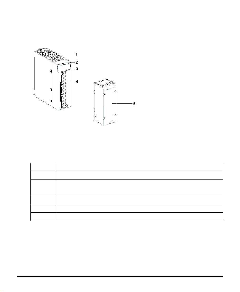
Illustration
The diagram below shows a 20-pin discrete module and a 20-pin terminal block.
Elements
The following table describes the different elements of the discrete input/output modules
with 20-pin terminal block connections.
Number Description
1 Rigid structure which supports and protects the electronic card
2 Module reference label
Note: A label is also visible on the right-hand side of the module.
3 Channel status display panel
4 Connector housing the 20-pin terminal block
5 20-pin terminal block, used to connect sensors or pre-actuators
NOTE: Terminal blocks are supplied separately.
20 35012474.18

General Introduction Discrete Input/Output Modules
Physical Description of Discrete Modules with 40-pin Terminal Block Connection
At a Glance
The I/O modules are housed in plastic cases which provide IP20 protection for all the
electronic parts.
Illustration
The diagram below shows a 40-pin discrete module and a 40-pin terminal block.
Elements
The following table describes the different elements of the discrete input/output modules
with 40-pin terminal block connections.
35012474.18 21
Discrete Input/Output Modules General Introduction
Number Description
1 Rigid structure which supports and protects the electronic card
2 Module reference label
Note: A label is also visible on the right-hand side of the module.
3 Channel status display panel
4 Connector housing the 40-pin terminal block
5 40-pin terminal block, used to connect sensors or pre-actuators
NOTE: Terminal blocks are supplied separately.
Physical Description of Discrete Modules with 40-Pin Connectors
At a Glance
The input/output modules are housed in plastic cases which provide IP20 protection for all
the electronic parts.
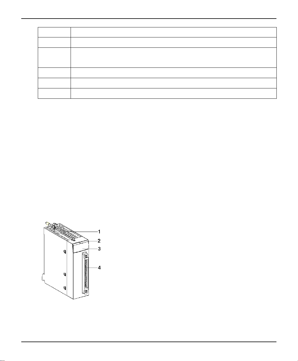
Illustration
The diagram below shows a 40-pin discrete module.
22 35012474.18

General Introduction Discrete Input/Output Modules
Elements
The following table describes the different elements of the discrete input/output modules by
40-pin connectors.
Number Description
1 Rigid structure which supports and protects the electronic card
2 Module reference labels
Note: A label is also visible on the right-hand side of the module.
3 Channel status display panel
4 40-pin connector, used to connect sensors or pre-actuators
Discrete Input Modules Catalog
At a Glance
The tables below present the two catalogs of discrete input modules:
• with 20-pin and 40-pin terminal blocks
• with 40-pin connectors
Catalog of Terminal Block Input Modules
Catalog of discrete input modules with 20-pin terminal block connection.
Type of
module
Illustration
Number of
channels
35012474.18 23
Inputs with 20-pin terminal block connection
Discrete input module
16
inputs16inputs16inputs
16 inputs 16
inputs16inputs
8 inputs 8 inputs

Discrete Input/Output Modules General Introduction
Range 24 VDC 48 VDC 125
Insulation Insula-
IEC 61131-2
compliance
Logic Positive Positive Positive N/A Positive
Proximity
sensor
compatibility
Response
time
Type of
Interface
Reference BMX
ted
inputs
Type 3 Type 1 N/A Type 1 N/A Type 3 Type 3 Type 3 Type 2
2-wire DC and 3-wire PNP proximity
sensor (IEC 60947-5-2 standard
compliant)
4 ms 4 ms 5 ms 15 ms 10 ms 10 ms 10 ms 10 ms
20-pin
terminal
block
DDI
1602
Insulated
inputs
20-pin
terminal
block
BMX
DDI
1603
VDC
Insulated
inputs
20-pin
terminal
block
BMX
DDI
1604T
24 VAC 24 VDC 48 VAC 100...1-
Insulated inputs Insula-
ted
inputs
N/A N/A N/A N/A
or
Negative
N/A 2-wire DC and 3-wire PNP proximity sensor
(IEC 60947-5-2 standard compliant)
20-pin terminal block 20-pin
terminal
block
BMX DAI 1602 BMX
DAI
1603
Catalog of discrete input modules with 40-pin terminal block connection.
20 VAC
Insulated
inputs
20-pin
terminal
block
BMX
DAI
1604
100...120
VAC
channel
to
channel
isolated
inputs
20-pin
terminal
block
BMX DAI
0814
200...240 VAC
Insulated
inputs
20-pin
terminal
block
BMX
DAI
0805
Type
of
module
Illustration
Number
Inputs with 40-pin terminal block connection
Discrete input module
16 inputs 16 inputs 32 inputs 32 inputs
24 35012474.18

General Introduction Discrete Input/Output Modules
of
channels
Range
100...120 VAC 200...240 VAC 48 VDC 12/24 VDC
Insulation
IEC
61131-2
compliance
Logic
Proximity
sensor
compatibility
Response
time
Type
of
Interface
Reference
channel to channel
isolated inputs
Type 1 Type 1 Type 3 Type 3 (24 VDC input)
N/A N/A Positive Positive or Negative
2-wire and 3-wire proximity sensor (IEC 60947-5-2
standard compliant)
10 ms 10 ms 4 ms 4 ms
40-pin terminal block 40-pin terminal block 40-pin terminal block 40-pin terminal block
BMX DAI 1614 BMX DAI 1615 BMX DDI 3203 BMX DDI 3232
channel to channel
isolated inputs
Inputs insulated per
group of 16 channels
2-wire proximity sensor
3-wire PNP proximity
sensor
Inputs insulated per
group of 16 channels
N/A
Catalog of 40-pin Connector Input Modules
Catalog of discrete input modules with 40-pin connectors.
35012474.18 25

Discrete Input/Output Modules General Introduction
Type of module Inputs with connection via 40-pin connectors
Illustration
Number of channels 32 inputs 64 inputs
Range 24 VDC 24 VDC
Insulation Inputs insulated per group of 16 channels Inputs insulated per group of 16 channels
IEC 61131-2 compliance Type 1 No type
Logic Positive Positive
Proximity sensor
compatibility
Response time 4 ms 4 ms
Type of Interface 1 x 40-pin connector 2 x 40-pin connectors
Reference BMX DDI 3202 K BMX DDI 6402 K
Discrete input module
2-wire proximity sensor
3-wire PNP proximity sensor
Discrete input module
3-wire PNP proximity sensor
Discrete Output Modules Catalog
At a Glance
The tables below show the catalogs of static and relay output modules.
Catalog of Output Modules
Catalog of discrete static output modules with connection via 20-pin terminal blocks and 40pin connectors.
26 35012474.18

General Introduction Discrete Input/Output Modules
Type of module Static outputs with 20-pin terminal block
Illustration
Number of
channels
Range 24 VDC 24 VDC 24 VDC 24 VDC
Insulation Insulated outputs Insulated outputs Outputs insulated per group of 16 channels
Current 0.5 A 0.5 A 0.1 A 0.1 A
Overload
protection
Logic Positive Negative Positive Positive
Response time 1.2 ms 1.2 ms 1.2 ms 1.2 ms
connections
Discrete output module
16 outputs 16 outputs 32 outputs 64 outputs
Outputs protected against short-circuits and overloads with automatic or controlled reactivation
and fast electromagnet demagnetization circuit.
Static outputs with 40-pin connectors
Discrete output
module
Discrete output
module
Type of Interface 20-pin terminal block 20-pin terminal block 1 x 40-pin connector 2 x 40-pin connectors
Reference BMX DDO 1602 BMX DDO 1612 BMX DDO 3202 K BMX DDO 6402 K
Catalog of Relay Output Modules
Catalog of discrete relay output modules with 20-pin and 40-pin terminal block connection.
35012474.18 27

Discrete Input/Output Modules General Introduction
Type of module Relay outputs with 20-pin terminal block connections Relay outputs with
Illustration
Number of
channels
Range 125 VDC 24 VDC or
Insulation Outputs
Type of contact 8 insulated
Thermal current
per channel
Discrete output module
8 outputs 8 outputs 8 outputs 16 outputs 8 NO/NC outputs
24...240 VAC
insulated from
ground
channels
3 A 3 A 2 A 2 A 4 A
Outputs
insulated from
ground
8 insulated
channels
5...125 VDC or
24...240 VAC
Outputs
insulated from
ground
8 insulated
channels
24...48 VDC or
24...240 VAC
Outputs
insulated from
ground
1 common per
group of 8
channels
40-pin terminal block
connections
Discrete output
module
5...125 VDC or
24...240 VAC
Outputs insulated
from ground
8 insulated channels
Overload
protection
Logic Positive/
Response time 10 ms max 10 ms max 13 ms max 10 ms max 13 ms max
Type of
Interface
Reference BMX DRA
No protection No protection No protection No protection No protection
negative
20-pin terminal
block
0804T
Positive/
negative
20-pin terminal
block
BMX DRA 0805 BMX DRA 0815 BMX DRA 1605 BMX DRC 0805
Positive/
negative
20-pin terminal
block
Positive/
negative
20-pin terminal
block
Positive/negative
40-pin terminal block
Catalog of Triac Output Module
Catalog of discrete triac output module with connection via 20-pin and 40-pin terminal
blocks.
28 35012474.18

General Introduction Discrete Input/Output Modules
Type of module Triac outputs with 20-pin terminal block
Illustration
Number of
channels
Range 100...240 VAC 24...240 VAC
Insulation Outputs insulated by group of 4 channels Outputs individually insulated
Current max: 0.6 A / points (with derating, page 34) max: 3 A per channel (with derating, page
Overload protection Snubber circuit and varistor Snubber circuit and varistor
Logic
connections
Discrete output module
16 outputs 16 outputs
- -
Triac outputs with 40-pin terminal block
connections
Discrete output module
264)
Response time 1 ms + 0.5 x (1/F)
(where F = frequency in Hz)
Type of Interface 20-pin terminal block 40-pin terminal block
Reference BMX DAO 1605 BMX DAO 1615
max: 0.5 x (1/F)
(where F = frequency in Hz)
Discrete Mixed Input/Output Modules Catalog
At a Glance
The table below presents the catalog of discrete mixed input/output modules with
connections by 20-pin terminal block and by 40-pin connectors.
35012474.18 29

Discrete Input/Output Modules General Introduction
Catalog
Catalog of discrete mixed input/output modules with connection via 20-pin terminal blocks
and 40-pin connectors.
Type of module Mixed inputs/outputs with 20-pin terminal block
Illustration
Number of
channels
Inputs Range 24 VDC 24 VDC 24 VDC
Insulation Insulated inputs Insulated inputs Insulated inputs
IEC 61131-2
compliant
Logic Positive Positive Positive
Response time 4 ms 4 ms 4 ms
connections
Discrete mixed input/output modules
8 inputs
8 outputs
Type 3 Type 3 Type 1
8 inputs
8 outputs
Mixed inputs/outputs with
40-pin terminal block
connections
Discrete mixed input/
output modules
16 inputs
16 outputs
Outputs Range Static outputs
24 VDC
Insulation Outputs insulated from
Current 0.5 A 2 A 0.1 A
IEC 61131-2
compliant
Overload
protection
ground
Yes Yes Yes
Outputs are protected
against overloads and
short-circuits.
Relay outputs
24 VDC or
24...240 VAC
Outputs insulated from
ground
1 common per group of
8 channels
N/A Outputs are protected
Static outputs
24 VDC
Outputs insulated from
ground
against overloads and
short-circuits.
30 35012474.18
 Loading...