

Page 1
Modicon M262 Logic/M otion Controller
EIO0000003651 05/2020
Modicon M262
Logic/Motion Controller
Programming Guide
05/2020
EIO0000003651.04
www.schneider-electric.com
Page 2

The information provided in this documentation contains general descriptions and/or technical
characteristics of the performance of the products contained herein. This documentation is not
intended as a substitute for and is not to be used for determining suitability or reliability of these
products for specific user applications. It is the duty of any such user or integrator to perform the
appropriate and complete risk analysis, evaluation and testing of the products with respect to the
relevant specific application or use thereof. Neither Schneider Electric nor any of its affiliates or
subsidiaries shall be responsible or liable for misuse of the information contained herein. If you
have any suggestions for improvements or amendments or have found errors in this publication,
please notify us.
You agree not to reproduce, other than for your own personal, noncommercial use, all or part of
this document on any medium whatsoever without permission of Schneider Electric, given in
writing. You also agree not to establish any hypertext links to this document or its content.
Schneider Electric does not grant any right or license for the personal and noncommercial use of
the document or its content, except for a non-exclusive license to consult it on an "as is" basis, at
your own risk. All other rights are reserved.
All pertinent state, regional, and local safety regulations must be observed when installing and
using this product. For reasons of safety and to help ensure compliance with documented system
data, only the manufacturer should perform repairs to components.
When devices are used for applications with technical safety requirements, the relevant
instructions must be followed.
Failure to use Schneider Electric software or approved software with our hardware products may
result in injury, harm, or improper operating results.
Failure to observe this information can result in injury or equipment damage.
© 2020 Schneider Electric. All rights reserved.
2 EIO0000003651 05/2020
Page 3

Table of Contents
Safety Information. . . . . . . . . . . . . . . . . . . . . . . . . . . . . . 7
About the Book . . . . . . . . . . . . . . . . . . . . . . . . . . . . . . . . 9
Chapter 1 About the Modicon M262 Logic/Motion Controller . . . . . 15
M262 Logic/Motion Controller Description. . . . . . . . . . . . . . . . . . . . . .
Chapter 2 Modicon M262 Motion Controller . . . . . . . . . . . . . . . . . . 19
Modicon M262 Motion Controller. . . . . . . . . . . . . . . . . . . . . . . . . . . . .
Chapter 3 How to Configure the Controller . . . . . . . . . . . . . . . . . . . 21
Configuring the Controller . . . . . . . . . . . . . . . . . . . . . . . . . . . . . . . . . .
Chapter 4 Libraries . . . . . . . . . . . . . . . . . . . . . . . . . . . . . . . . . . . . . 23
Libraries. . . . . . . . . . . . . . . . . . . . . . . . . . . . . . . . . . . . . . . . . . . . . . . .
Chapter 5 Supported Standard Data Types . . . . . . . . . . . . . . . . . . 25
Supported Standard Data Types . . . . . . . . . . . . . . . . . . . . . . . . . . . . .
Chapter 6 Memory Mapping . . . . . . . . . . . . . . . . . . . . . . . . . . . . . . 27
Controller Memory Organization . . . . . . . . . . . . . . . . . . . . . . . . . . . . .
Flash Memory Organization . . . . . . . . . . . . . . . . . . . . . . . . . . . . . . . .
RAM Memory Organization . . . . . . . . . . . . . . . . . . . . . . . . . . . . . . . . .
NVRAM Memory Organization . . . . . . . . . . . . . . . . . . . . . . . . . . . . . .
Relocation Table . . . . . . . . . . . . . . . . . . . . . . . . . . . . . . . . . . . . . . . . .
Chapter 7 Tasks . . . . . . . . . . . . . . . . . . . . . . . . . . . . . . . . . . . . . . . 39
Maximum Number of Tasks. . . . . . . . . . . . . . . . . . . . . . . . . . . . . . . . .
Task Types . . . . . . . . . . . . . . . . . . . . . . . . . . . . . . . . . . . . . . . . . . . . .
Task Configuration Screen . . . . . . . . . . . . . . . . . . . . . . . . . . . . . . . . .
System and Task Watchdogs . . . . . . . . . . . . . . . . . . . . . . . . . . . . . . .
Task Priorities . . . . . . . . . . . . . . . . . . . . . . . . . . . . . . . . . . . . . . . . . . .
Default Task Configuration . . . . . . . . . . . . . . . . . . . . . . . . . . . . . . . . .
Chapter 8 Controller States and Behaviors . . . . . . . . . . . . . . . . . . . 51
8.1 Controller State Diagram . . . . . . . . . . . . . . . . . . . . . . . . . . . . . . . . . . .
Controller State Diagram . . . . . . . . . . . . . . . . . . . . . . . . . . . . . . . . . . .
8.2 Controller States Description. . . . . . . . . . . . . . . . . . . . . . . . . . . . . . . .
Controller States Description. . . . . . . . . . . . . . . . . . . . . . . . . . . . . . . .
8.3 State Transitions and System Events . . . . . . . . . . . . . . . . . . . . . . . . .
Controller States and Output Behavior . . . . . . . . . . . . . . . . . . . . . . . .
Commanding State Transitions . . . . . . . . . . . . . . . . . . . . . . . . . . . . . .
Error Detection, Types, and Management. . . . . . . . . . . . . . . . . . . . . .
Remanent Variables . . . . . . . . . . . . . . . . . . . . . . . . . . . . . . . . . . . . . .
15
19
21
23
25
28
30
33
35
36
40
41
45
47
48
50
52
52
56
56
60
61
64
70
71
EIO0000003651 05/2020 3
Page 4

Chapter 9 Controller Device Editor . . . . . . . . . . . . . . . . . . . . . . . . . . 73
Controller Parameters . . . . . . . . . . . . . . . . . . . . . . . . . . . . . . . . . . . . .
Communication Settings . . . . . . . . . . . . . . . . . . . . . . . . . . . . . . . . . . .
PLC Settings . . . . . . . . . . . . . . . . . . . . . . . . . . . . . . . . . . . . . . . . . . . .
Services . . . . . . . . . . . . . . . . . . . . . . . . . . . . . . . . . . . . . . . . . . . . . . . .
Ethernet Services. . . . . . . . . . . . . . . . . . . . . . . . . . . . . . . . . . . . . . . . .
Users Rights . . . . . . . . . . . . . . . . . . . . . . . . . . . . . . . . . . . . . . . . . . . .
74
76
77
79
81
85
Chapter 10 Embedded Inputs and Outputs Configuration . . . . . . . . . 87
10.1 Configuring the Fast I/Os . . . . . . . . . . . . . . . . . . . . . . . . . . . . . . . . . . .
Embedded I/Os Configuration . . . . . . . . . . . . . . . . . . . . . . . . . . . . . . .
10.2 Hardware Encoder Interface . . . . . . . . . . . . . . . . . . . . . . . . . . . . . . . .
Hardware Encoder Interface . . . . . . . . . . . . . . . . . . . . . . . . . . . . . . . .
Adding an Encoder. . . . . . . . . . . . . . . . . . . . . . . . . . . . . . . . . . . . . . . .
Encoder Motion Functions . . . . . . . . . . . . . . . . . . . . . . . . . . . . . . . . . .
88
88
94
95
97
100
Chapter 11 Expansion Modules Configuration . . . . . . . . . . . . . . . . . . 101
TM3 I/O Configuration General Description. . . . . . . . . . . . . . . . . . . . .
TM3 I/O Bus Configuration. . . . . . . . . . . . . . . . . . . . . . . . . . . . . . . . . .
TMS Expansion Module Configuration. . . . . . . . . . . . . . . . . . . . . . . . .
TM3 Expansion Module Configuration . . . . . . . . . . . . . . . . . . . . . . . . .
Optional I/O Expansion Modules . . . . . . . . . . . . . . . . . . . . . . . . . . . . .
102
106
107
108
109
Chapter 12 Ethernet Configuration . . . . . . . . . . . . . . . . . . . . . . . . . . . 113
12.1 Ethernet Services. . . . . . . . . . . . . . . . . . . . . . . . . . . . . . . . . . . . . . . . .
Presentation . . . . . . . . . . . . . . . . . . . . . . . . . . . . . . . . . . . . . . . . . . . . .
IP Address Configuration . . . . . . . . . . . . . . . . . . . . . . . . . . . . . . . . . . .
Modbus TCP Client/Server . . . . . . . . . . . . . . . . . . . . . . . . . . . . . . . . .
Web Server . . . . . . . . . . . . . . . . . . . . . . . . . . . . . . . . . . . . . . . . . . . . .
Symbol Configuration Editor . . . . . . . . . . . . . . . . . . . . . . . . . . . . . . . .
FTP Server. . . . . . . . . . . . . . . . . . . . . . . . . . . . . . . . . . . . . . . . . . . . . .
SNMP. . . . . . . . . . . . . . . . . . . . . . . . . . . . . . . . . . . . . . . . . . . . . . . . . .
Controller as a Target Device on EtherNet/IP . . . . . . . . . . . . . . . . . . .
Controller as a Slave Device on Modbus TCP. . . . . . . . . . . . . . . . . . .
12.2 Firewall Configuration . . . . . . . . . . . . . . . . . . . . . . . . . . . . . . . . . . . . .
Introduction . . . . . . . . . . . . . . . . . . . . . . . . . . . . . . . . . . . . . . . . . . . . .
Dynamic Changes Procedure . . . . . . . . . . . . . . . . . . . . . . . . . . . . . . .
Firewall Behavior . . . . . . . . . . . . . . . . . . . . . . . . . . . . . . . . . . . . . . . . .
Firewall Script Commands . . . . . . . . . . . . . . . . . . . . . . . . . . . . . . . . . .
114
115
117
123
125
149
155
156
157
182
187
188
190
191
193
4 EIO0000003651 05/2020
Page 5

Chapter 13 Industrial Ethernet. . . . . . . . . . . . . . . . . . . . . . . . . . . . . . 201
Industrial Ethernet Presentation . . . . . . . . . . . . . . . . . . . . . . . . . . . . .
DHCP Server. . . . . . . . . . . . . . . . . . . . . . . . . . . . . . . . . . . . . . . . . . . .
Fast Device Replacement . . . . . . . . . . . . . . . . . . . . . . . . . . . . . . . . . .
202
207
208
Chapter 14 Sercos Configuration . . . . . . . . . . . . . . . . . . . . . . . . . . . 209
Overview of the Sercos Standard . . . . . . . . . . . . . . . . . . . . . . . . . . . .
Modicon M262 Logic/Motion Controller Sercos Configuration . . . . . .
Modicon M262 Motion Controller and Safety Controllers with Sercos
Single Wire Architecture . . . . . . . . . . . . . . . . . . . . . . . . . . . . . . . . . . .
210
212
213
214
Chapter 15 Serial Line Configuration . . . . . . . . . . . . . . . . . . . . . . . . 217
Serial Line Configuration . . . . . . . . . . . . . . . . . . . . . . . . . . . . . . . . . . .
Machine Expert Network Manager . . . . . . . . . . . . . . . . . . . . . . . . . . .
Modbus Manager. . . . . . . . . . . . . . . . . . . . . . . . . . . . . . . . . . . . . . . . .
ASCII Manager . . . . . . . . . . . . . . . . . . . . . . . . . . . . . . . . . . . . . . . . . .
Modbus Serial IOScanner . . . . . . . . . . . . . . . . . . . . . . . . . . . . . . . . . .
Adding a Device on the Modbus Serial IOScanner . . . . . . . . . . . . . . .
Adding a Modem to a Manager . . . . . . . . . . . . . . . . . . . . . . . . . . . . . .
218
220
221
225
227
229
235
Chapter 16 OPC UA . . . . . . . . . . . . . . . . . . . . . . . . . . . . . . . . . . . . . 237
16.1 Overview . . . . . . . . . . . . . . . . . . . . . . . . . . . . . . . . . . . . . . . . . . . . . . .
OPC UA Overview. . . . . . . . . . . . . . . . . . . . . . . . . . . . . . . . . . . . . . . .
16.2 OPC UA Server Configuration. . . . . . . . . . . . . . . . . . . . . . . . . . . . . . .
OPC UA Server Overview . . . . . . . . . . . . . . . . . . . . . . . . . . . . . . . . . .
OPC UA Server Configuration. . . . . . . . . . . . . . . . . . . . . . . . . . . . . . .
OPC UA Server Symbols Configuration . . . . . . . . . . . . . . . . . . . . . . .
OPC UA Server Performance . . . . . . . . . . . . . . . . . . . . . . . . . . . . . . .
16.3 OPC UA Client Configuration . . . . . . . . . . . . . . . . . . . . . . . . . . . . . . .
OPC UA Client Overview. . . . . . . . . . . . . . . . . . . . . . . . . . . . . . . . . . .
Programming the OPC UA Client . . . . . . . . . . . . . . . . . . . . . . . . . . . .
238
238
239
240
241
244
246
249
250
251
Chapter 17 Post Configuration . . . . . . . . . . . . . . . . . . . . . . . . . . . . . 253
Post Configuration Presentation . . . . . . . . . . . . . . . . . . . . . . . . . . . . .
Post Configuration File Management . . . . . . . . . . . . . . . . . . . . . . . . .
Post Configuration Example . . . . . . . . . . . . . . . . . . . . . . . . . . . . . . . .
254
255
257
Chapter 18 Connecting a Modicon M262 Logic/Motion Controller to a
PC. . . . . . . . . . . . . . . . . . . . . . . . . . . . . . . . . . . . . . . . . . 259
Connecting the Controller to a PC . . . . . . . . . . . . . . . . . . . . . . . . . . . .
259
EIO0000003651 05/2020 5
Page 6

Chapter 19 Updating Firmware . . . . . . . . . . . . . . . . . . . . . . . . . . . . . . 261
Updating the Controller Firmware by SD Card. . . . . . . . . . . . . . . . . . .
Updating the Controller Firmware by Controller Assistant . . . . . . . . . .
Updating TM3 Expansion Modules Firmware . . . . . . . . . . . . . . . . . . .
Updating TMS Expansion Modules Firmware . . . . . . . . . . . . . . . . . . .
Chapter 20 Managing Script Files. . . . . . . . . . . . . . . . . . . . . . . . . . . . 273
Creating a Script . . . . . . . . . . . . . . . . . . . . . . . . . . . . . . . . . . . . . . . . .
Generating Scripts and Files . . . . . . . . . . . . . . . . . . . . . . . . . . . . . . . .
Transferring Scripts and Files . . . . . . . . . . . . . . . . . . . . . . . . . . . . . . .
Chapter 21 Cloning a Controller . . . . . . . . . . . . . . . . . . . . . . . . . . . . . 283
Before Cloning a Controller . . . . . . . . . . . . . . . . . . . . . . . . . . . . . . . . .
Cloning a Controller . . . . . . . . . . . . . . . . . . . . . . . . . . . . . . . . . . . . . . .
Chapter 22 Compatibility. . . . . . . . . . . . . . . . . . . . . . . . . . . . . . . . . . . 289
Software and Firmware Compatibilities . . . . . . . . . . . . . . . . . . . . . . . .
Chapter 23 Industrial Plug and Work . . . . . . . . . . . . . . . . . . . . . . . . . 291
23.1 Accessing the Web Server. . . . . . . . . . . . . . . . . . . . . . . . . . . . . . . . . .
Launching the Web Server. . . . . . . . . . . . . . . . . . . . . . . . . . . . . . . . . .
23.2 Using the Machine Assistant . . . . . . . . . . . . . . . . . . . . . . . . . . . . . . . .
Launching the Machine Assistant . . . . . . . . . . . . . . . . . . . . . . . . . . . .
Managing the Network Scan . . . . . . . . . . . . . . . . . . . . . . . . . . . . . . . .
Managing the Devices Network Settings . . . . . . . . . . . . . . . . . . . . . . .
Backing Up/Restoring Configuration . . . . . . . . . . . . . . . . . . . . . . . . . .
Exporting/Importing .semdt Files . . . . . . . . . . . . . . . . . . . . . . . . . . . . .
Appendices . . . . . . . . . . . . . . . . . . . . . . . . . . . . . . . . . . . . . . . . .
Appendix A How to Change the IP Address of the Controller . . . . . . . 303
changeIPAddress: Change the IP address of the controller . . . . . . . .
Appendix B Functions to Get/Set Serial Line Configuration in User
Program . . . . . . . . . . . . . . . . . . . . . . . . . . . . . . . . . . . . . . 307
GetSerialConf: Get the Serial Line Configuration . . . . . . . . . . . . . . . .
SetSerialConf: Change the Serial Line Configuration . . . . . . . . . . . . .
SERIAL_CONF: Structure of the Serial Line Configuration Data Type
Appendix C Controller Performance . . . . . . . . . . . . . . . . . . . . . . . . . . 313
Processing Performance . . . . . . . . . . . . . . . . . . . . . . . . . . . . . . . . . . .
Glossary . . . . . . . . . . . . . . . . . . . . . . . . . . . . . . . . . . . . . . . . .
Index . . . . . . . . . . . . . . . . . . . . . . . . . . . . . . . . . . . . . . . . .
262
265
268
271
274
279
280
284
286
289
292
292
293
294
295
297
299
300
301
303
308
309
311
313
315
327
6 EIO0000003651 05/2020
Page 7
Safety Information
Important Information
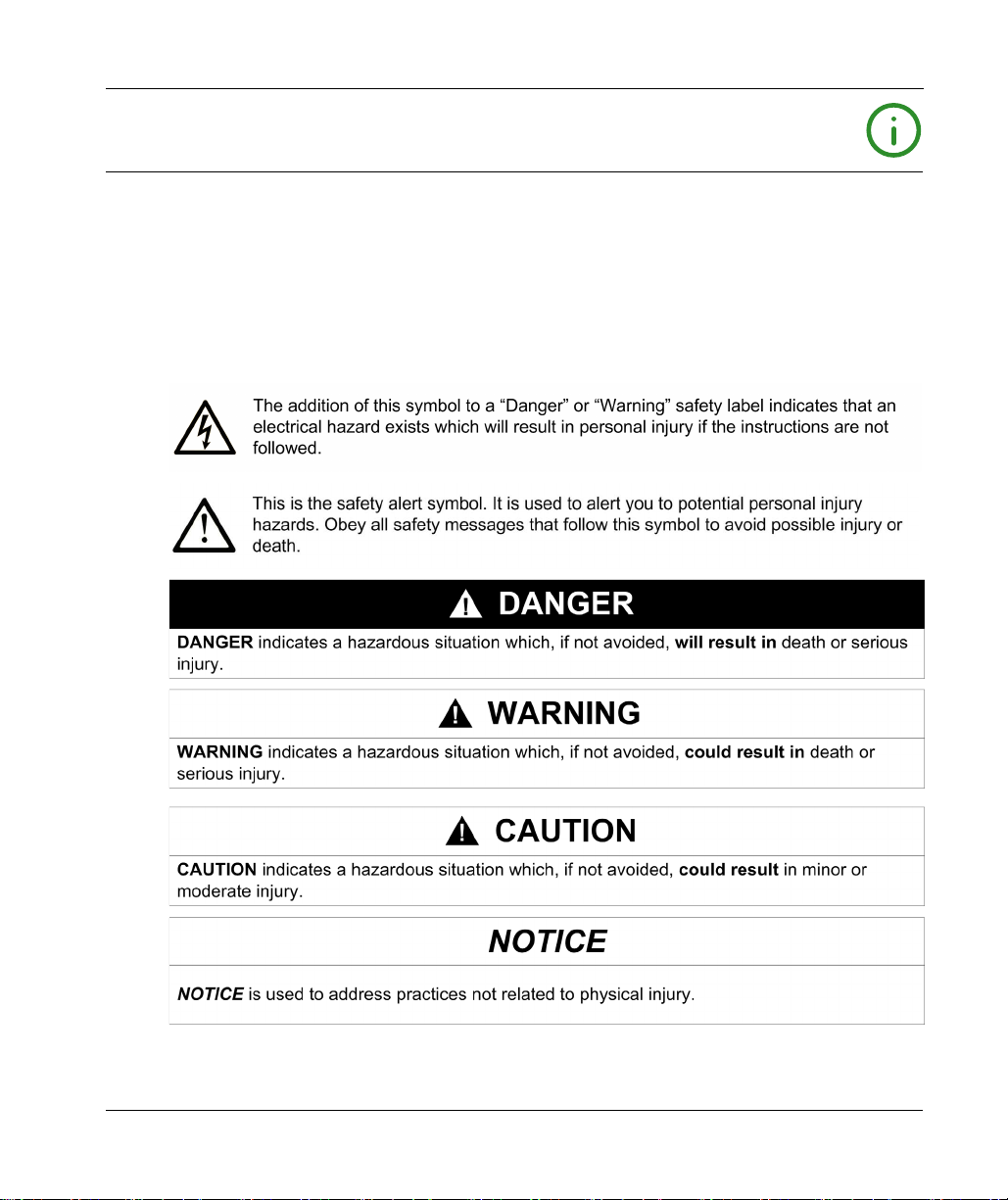
NOTICE
Read these instructions carefully, and look at the equipment to become familiar with the device
before trying to install, operate, service, or maintain it. The following special messages may appear
throughout this documentation or on the equipment to warn of potential hazards or to call attention
to information that clarifies or simplifies a procedure.
EIO0000003651 05/2020 7
Page 8

PLEASE NOTE
Electrical equipment should be installed, operated, serviced, and maintained only by qualified
personnel. No responsibility is assumed by Schneider Electric for any consequences arising out of
the use of this material.
A qualified person is one who has skills and knowledge related to the construction and operation
of electrical equipment and its installation, and has received safety training to recognize and avoid
the hazards involved.
8 EIO0000003651 05/2020
Page 9

About the Book
At a Glance
Document Scope
The purpose of this document is to help you to program and operate your Modicon M262
Logic/Motion Controller with the EcoStruxure Machine Expert software.
NOTE: Read and understand this document and all related documents before installing, operating,
or maintaining your Modicon M262 Logic/Motion Controller.
The Modicon M262 Logic/Motion Controller users should read through the entire document to
understand all features.
Validity Note
This document has been updated for the release of EcoStruxure
The technical characteristics of the devices described in the present document also appear online.
To access the information online, go to the Schneider Electric home page
https://www.se.com/ww/en/download/
The characteristics that are described in the present document should be the same as those
characteristics that appear online. In line with our policy of constant improvement, we may revise
content over time to improve clarity and accuracy. If you see a difference between the document
and online information, use the online information as your reference.
TM
Machine Expert V1.2.3.
.
EIO0000003651 05/2020 9
Page 10

Related Documents
Title of Documentation Reference Number
EcoStruxure Machine Expert - Programming Guide
Modicon M262 Logic/Motion Controller - Hardware Guide
Modicon TM3 Expansion Modules Configuration - Programming
Guide
Modicon TM5 EtherNet/IP Fieldbus Interface - Programming Guide
Modicon TMS Expansion Modules - Programming Guide
EIO0000002854 (ENG)
EIO0000002855 (FRE)
EIO0000002856 (GER)
EIO0000002857 (SPA)
EIO0000002858 (ITA)
EIO0000002859 (CHS)
EIO0000003659 (ENG)
EIO0000003660 (FRE)
EIO0000003661 (GER)
EIO0000003662 (SPA)
EIO0000003663 (ITA)
EIO0000003664 (CHS)
EIO0000003665 (POR)
EIO0000003666 (TUR)
EIO0000001402 (ENG)
EIO0000001403 (FRE)
EIO0000001404 (GER)
EIO0000001405 (SPA)
EIO0000001406 (ITA)
EIO0000001407 (CHS)
EIO0000003707 (ENG)
EIO0000003708(FRE)
EIO0000003709 (GER)
EIO0000003710 (SPA)
EIO0000003711 (ITA)
EIO0000003712 (CHS)
EIO0000003691 (ENG)
EIO0000003692 (FRE)
EIO0000003693 (GER)
EIO0000003694 (SPA)
EIO0000003695 (ITA)
EIO0000003696 (CHS)
EIO0000003697 (POR)
EIO0000003698 (TUR)
10 EIO0000003651 05/2020
Page 11

Title of Documentation Reference Number
Modicon M262 Logic/Motion Controller - System Library Guide
EIO0000003667 (ENG)
EIO0000003668 (FRE)
EIO0000003669 (GER)
EIO0000003670 (SPA)
EIO0000003671 (ITA)
EIO0000003672 (CHS)
EIO0000003673 (POR)
EIO0000003674 (TUR)
Modicon TM3 Expert I/O Modules - HSC Library Guide
EIO0000003683 (ENG)
EIO0000003684 (FRE)
EIO0000003685 (GER)
EIO0000003686 (SPA)
EIO0000003687 (ITA)
EIO0000003688 (CHS)
EIO0000003689 (POR)
EIO0000003690 (TUR)
Modicon M262 Logic/Motion Controller - Encoder Library Guide
EIO0000003675 (ENG)
EIO0000003676(FRE)
EIO0000003677(GER)
EIO0000003678 (SPA)
EIO0000003679 (ITA)
EIO0000003680 (CHS)
EIO0000003681 (POR)
EIO0000003682 (TUR)
M262 Embedded Safety - Integration Guide
EIO0000003921 (ENG)
EIO0000003923 (FRE)
EIO0000003922 (GER)
EIO0000003926 (SPA)
EIO0000003924 (ITA)
EIO0000003925 (CHS)
Sercos for M262 - User Guide
EIO0000003883 (ENG)
EIO0000003885 (FRE)
EIO0000003884 (GER)
EIO0000003888 (SPA)
EIO0000003886 (ITA)
EIO0000003887 (CHS)
Controller Assistant - User Guide
EIO0000001671 (ENG)
EIO0000001672 (FRE)
EIO0000001673 (GER)
EIO0000001675 (SPA)
EIO0000001674 (ITA)
EIO0000001676 (CHS)
EIO0000003651 05/2020 11
Page 12
Title of Documentation Reference Number
EcoStruxure Machine Expert - FtpRemoteFileHandling Library Guide
EcoStruxure Machine Expert - SnmpManager Library Guide
You can download these technical publications and other technical information from our website
at https://www.se.com/ww/en/download/ .
Product Related Information
LOSS OF CONTROL
The designer of any control scheme must consider the potential failure modes of control paths
and, for certain critical control functions, provide a means to achieve a safe state during and
after a path failure. Examples of critical control functions are emergency stop and overtravel
stop, power outage and restart.
Separate or redundant control paths must be provided for critical control functions.
System control paths may include communication links. Consideration must be given to the
implications of unanticipated transmission delays or failures of the link.
Observe all accident prevention regulations and local safety guidelines.
Each implementation of this equipment must be individually and thoroughly tested for proper
operation before being placed into service.
Failure to follow these instructions can result in death, serious injury, or equipment damage.
EIO0000002779 (ENG)
EIO0000002780 (FRE)
EIO0000002781 (GER)
EIO0000002782 (SPA)
EIO0000002783 (ITA)
EIO0000002784 (CHS)
EIO0000002797 (ENG)
EIO0000002798 (FRE)
EIO0000002799 (GER)
EIO0000002800 (SPA)
EIO0000002801 (ITA)
EIO0000002802 (CHS)
WARNING
1
1
For additional information, refer to NEMA ICS 1.1 (latest edition), "Safety Guidelines for the
Application, Installation, and Maintenance of Solid State Control" and to NEMA ICS 7.1 (latest
edition), "Safety Standards for Construction and Guide for Selection, Installation and Operation of
Adjustable-Speed Drive Systems" or their equivalent governing your particular location.
12 EIO0000003651 05/2020
Page 13

UNINTENDED EQUIPMENT OPERATION
Only use software approved by Schneider Electric for use with this equipment.
Update your application program every time you change the physical hardware configuration.
Failure to follow these instructions can result in death, serious injury, or equipment damage.
Terminology Derived from Standards
The technical terms, terminology, symbols and the corresponding descriptions in this manual, or
that appear in or on the products themselves, are generally derived from the terms or definitions
of international standards.
In the area of functional safety systems, drives and general automation, this may include, but is not
limited to, terms such as
safety, safety function, safe state, fault, fault reset, malfunction, failure
error, error message, dangerous
Among others, these standards include:
Standard Description
IEC 61131-2:2007 Programmable controllers, part 2: Equipment requirements and tests.
ISO 13849-1:2015 Safety of machinery: Safety related parts of control systems.
EN 61496-1:2013 Safety of machinery: Electro-sensitive protective equipment.
ISO 12100:2010 Safety of machinery - General principles for design - Risk assessment and risk
EN 60204-1:2006 Safety of machinery - Electrical equipment of machines - Part 1: General
ISO 14119:2013 Safety of machinery - Interlocking devices associated with guards - Principles
ISO 13850:2015 Safety of machinery - Emergency stop - Principles for design
IEC 62061:2015 Safety of machinery - Functional safety of safety-related electrical, electronic,
IEC 61508-1:2010 Functional safety of electrical/electronic/programmable electronic safety-
IEC 61508-2:2010 Functional safety of electrical/electronic/programmable electronic safety-
IEC 61508-3:2010 Functional safety of electrical/electronic/programmable electronic safety-
IEC 61784-3:2016 Industrial communication networks - Profiles - Part 3: Functional safety
General principles for design.
Part 1: General requirements and tests.
reduction
requirements
for design and selection
and electronic programmable control systems
related systems: General requirements.
related systems: Requirements for electrical/electronic/programmable
electronic safety-related systems.
related systems: Software requirements.
fieldbuses - General rules and profile definitions.
WARNING
,
, etc.
EIO0000003651 05/2020 13
Page 14
Standard Description
2006/42/EC Machinery Directive
2014/30/EU Electromagnetic Compatibility Directive
2014/35/EU Low Voltage Directive
In addition, terms used in the present document may tangentially be used as they are derived from
other standards such as:
Standard Description
IEC 60034 series Rotating electrical machines
IEC 61800 series Adjustable speed electrical power drive systems
IEC 61158 series Digital data communications for measurement and control – Fieldbus for use in
industrial control systems
Finally, the term
hazards, and is defined as it is for a
2006/42/EC
(
zone of operation
) and
ISO 12100:2010
may be used in conjunction with the description of specific
hazard zone
or
danger zone
in the
Machinery Directive
.
NOTE: The aforementioned standards may or may not apply to the specific products cited in the
present documentation. For more information concerning the individual standards applicable to the
products described herein, see the characteristics tables for those product references.
14 EIO0000003651 05/2020
Page 15

Modicon M262 Logic/Moti on Controller
About the Modicon M26 2 Logic/Motion Con troller
EIO0000003651 05/2020
About the Modicon M26 2 Logic/Motion Con troller
Chapter 1
About the Modicon M262 Logic/Motion Controller
M262 Logic/Motion Controller Description
Overview
The M262 Logic/Motion Controller has various powerful features and can service a wide range of
applications.
Software configuration, programming, and commissioning are accomplished with the EcoStruxure
Machine Expert software version 1.1 or later, described in detail in the EcoStruxure Machine
Expert Programming Guide as well as the present document.
Programming Languages
The M262 Logic/Motion Controller is configured and programmed with the EcoStruxure Machine
Expert software, which supports the following IEC 61131-3 programming languages:
IL: Instruction List
ST: Structured Text
FBD: Function Block Diagram
SFC: Sequential Function Chart
LD: Ladder Diagram
EcoStruxure Machine Expert software can also be used to program these controllers using CFC
(Continuous Function Chart) language.
Power Supply
The power supply of the M262 Logic/Motion Controller is 24 Vdc
Controller, Hardware Guide)
.
(see Modicon M262 Logic/Motion
Real Time Clock
The M262 Logic/Motion Controller includes a Real Time Clock (RTC) system
Logic/Motion Controller, Hardware Guide)
.
(see Modicon M262
The system time is maintained by capacitors when the power is off. The time is maintained for
1 000 hours when the controller is not supplied.
EIO0000003651 05/2020 15
Page 16

About the Modicon M262 Logic/Motion Controller
Run/Stop
The M262 Logic/Motion Controller can be operated externally by the following:
A hardware Run/Stop switch
A Run/Stop operation by a dedicated digital input, defined in the software configuration. For
(see Modicon M262 Logic/Motion Controller, Hardware Guide)
more information, refer to Configuration of Digital Inputs
An EcoStruxure Machine Expert software command.
The system variable PLC_W in a Relocation Table
The Web server
(see page 125)
Memory
This table describes the different types of memory:
Memory Type Size Use
RAM 256 Mbytes, of which 32 Mbytes are
available for the application
Flash 1 Gbyte Non-volatile memory dedicated to the retention
Non-volatile RAM 512 Kbytes Non-volatile memory dedicated to the retention
Embedded Inputs/Outputs
The following embedded I/O types are available:
Fast inputs
Fast source outputs
.
(see page 89)
(seepage36)
.
.
.
For the execution of the application and the
firmware.
of the program and data in case of a power
interruption.
of the retain-persistent variables, and the
diagnostic files and associated information.
Encoder
The following encoder modes are available:
Incremental mode
SSI mode
Removable Storage
The M262 Logic/Motion Controllers include an integrated SD card slot
Logic/Motion Controller, Hardware Guide)
The main uses of the SD card are:
Initializing the controller with a new application
Updating the controller and expansion module firmware
Applying post configuration files to the controller
Storing recipes files
Receiving data logging files
16
(see Modicon M262
.
(see page 261)
(see page 254)
EIO0000003651 05/2020
Page 17
About the Modicon M262 Logic/Motion Controller
Embedded Communication Features
The following types of communication ports are available:
Ethernet
USB Mini-B
Serial Line
Sercos (Ethernet 1)
(see Modicon M262 Logic/Motion Controller, Hardware Guide)
(see Modicon M262 Logic/Motion Controller, Hardware Guide)
(see Modicon M262 Logic/Motion Controller, Hardware Guide)
Expansion Module and Bus Coupler Compatibility
Refer to the compatibility tables in the EcoStruxure Machine Expert - Compatibility and Migration
User Guide
(see EcoStruxure Machine Expert Compatibility and Migration, User Guide)
M262 Logic/Motion Controller
Reference Digital I/O Power supply Communication Ports Terminal Type Encoder
M262 Logic
Controller:
TM262L•
M262 Motion
Controller:
TM262M•
4 fast inputs
Source outputs
4 fast outputs
4 fast inputs
Source outputs
4 fast outputs
24 Vdc 1 serial line port
1 USB programming port
1 Ethernet port
1 dual port Ethernet switch
24 Vdc 1 serial line port
1 USB programming port
1 Ethernet port for fieldbus
with Sercos interface
1 dual port Ethernet switch
Removable
spring
Removable
spring
–
1 Encoder port
NOTE: You can use the fast inputs/outputs as regular inputs/outputs.
.
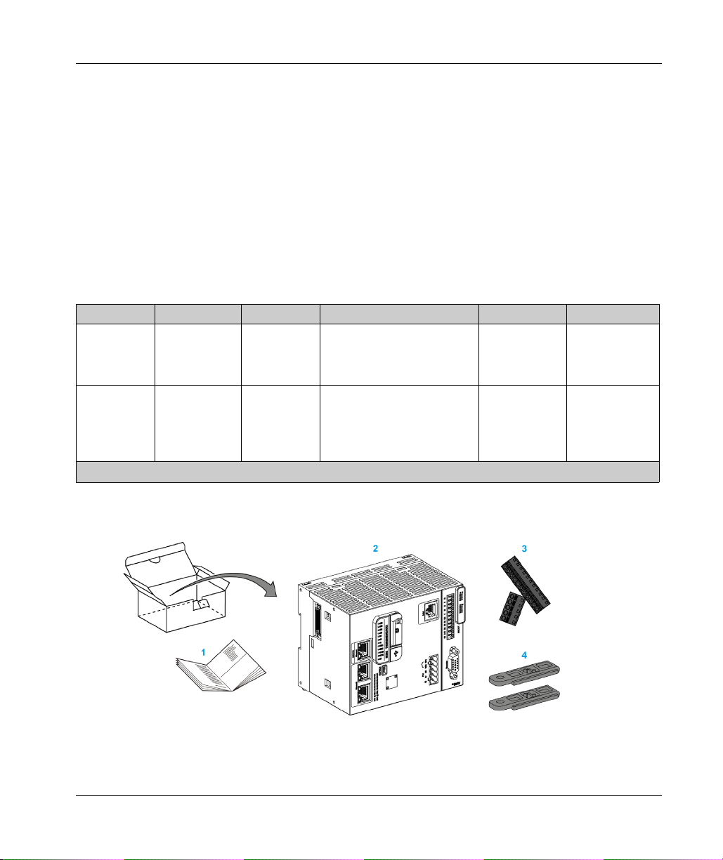
Delivery Content
The following figure presents the content of the delivery for the M262 Logic/Motion Controller:
1 M262 Logic/Motion Controller Instruction Sheet
2 M262 Logic/Motion Controller
3 Removable spring terminal blocks
4 Attachment parts
EIO0000003651 05/2020 17
Page 18

About the Modicon M262 Logic/Motion Controller
18
EIO0000003651 05/2020
Page 19

Modicon M262 Logic/Moti on Controller
M262 Motion Controller
EIO0000003651 05/2020
Modicon M262 Motion Co ntroller
Chapter 2
Modicon M262 Motion Controller
Modicon M262 Motion Controller
Controller Overview
The Schneider Electric Modicon TM262M15MESS8T, TM262M25MESS8T and
TM262M35MESS8T are controllers with various powerful features which can control a wide range
of motion applications.
The Modicon TM262M• Motion Controller centrally implements the Logic Controller functions and
powerful advanced motion functions.
A Modicon TM262M• Motion Controller creates, synchronizes and coordinates the motion
functions of a machine for a maximum of 16 axes, synchronized in 2 ms.
These controllers are designed for axis positioning using the EcoStruxure Machine Expert software
platform.
Performance Overview
The Modicon TM262M• Motion Controller supports all the features normally available in our Logic
Controller, plus it integrates Motion functionalities.
The TM262M• range of Motion controllers is, without additional devices, ready for motion with the
integrated Sercos motion bus. It merges the hard-real-time aspects of the Sercos interface with
Ethernet. It is based upon and conforms to the Ethernet standard IEEE 802.3 and ISO/IEC 88023 to support the real-time application with high performance. Other features supporting motion
functionalities include:
Synchronous axis Sercos devices, managed by PLCopen libraries, are fully synchronous with
the internal Motion task and the Sercos Cycle time, as for example: LMX32S.
Non axis Sercos devices are also synchronized with the internal Motion task, for example,
TM5NS01 islands or safety-related TM5CSLC100/TM5CSLC200 controllers.
External Encoder
External port for Incremental or SSI encoder. The encoder support is fully synchronized with
the Motion application. It can be used like a real axis or a virtual axis.
Fast input
The fast inputs support a touch probe function to capture position. The captured position can
be used in the Motion application.
EIO0000003651 05/2020 19
Page 20

M262 Motion Controller
Motion Kernel is embedded in the TM262M• Motion controller, allowing you to manage the
motion functions:
Synchronous axis in coordinated move in which the Functions blocks are based on the
PLCopen Standard to control easily the position / speed of a single axis.
Gearing mode (Master / Slave Function Block).
Caming mode, based on recipes, with modification on fly. The recipe can be designed thanks
to a cam editor included in EcoStruxure Machine Expert.
Depending the Motion controller and the Sercos Cycle time, you can configure more or less
Synchronous axis and non axis Sercos devices.
A TM5 System island used on Sercos is managed as non axis Sercos device. These islands are
fully configurable. The number of I/O configured increases the load of the Sercos Bus and may lead
to an overflow. If an overflow occurs, and assuming your application tolerates it, increase the
Sercos Cycle time. If increasing the Sercos Cycle time is not compatible with your application, then
optimize the application.
The following table indicates the performance capabilities of the Motion application:
Controller reference Sercos cycle
time
TM262M15MESS8T 1 ms 4 1 4
2ms 4 1 12
4ms 4 1 12
TM262M25MESS8T 1 ms 4 1 8
2ms 8 2 8
4ms 8 2 16
TM262M35MESS8T 1 ms 8 2 8
2ms 16 4 8
4ms 16 4 24
Synchronized axes on
Sercos (activated and
simulated)
Additional virtual axes
FB_ControlledAxis
Additional
Sercos devices
The Motion Sizer is embedded in EcoStruxure Machine Expert to help you define your complete
kinematic architecture. For more information on these features, refer to OneMotionSizer Online
(see Motion Sizer, Online Help)
Help
.
20
EIO0000003651 05/2020
Page 21
Modicon M262 Logic/Moti on Controller
How to Configure the Controller
EIO0000003651 05/2020
How to Configure the Controller
Chapter 3
How to Configure the Controller
Configuring the Controller
Introduction
First, create a new project or open an existing project in the EcoStruxure Machine Expert software.
Refer to the EcoStruxure Machine Expert Programming Guide for information on how to:
Add a controller to your project
Add expansion modules to your controller
Replace an existing controller
Convert a controller to a different but compatible device
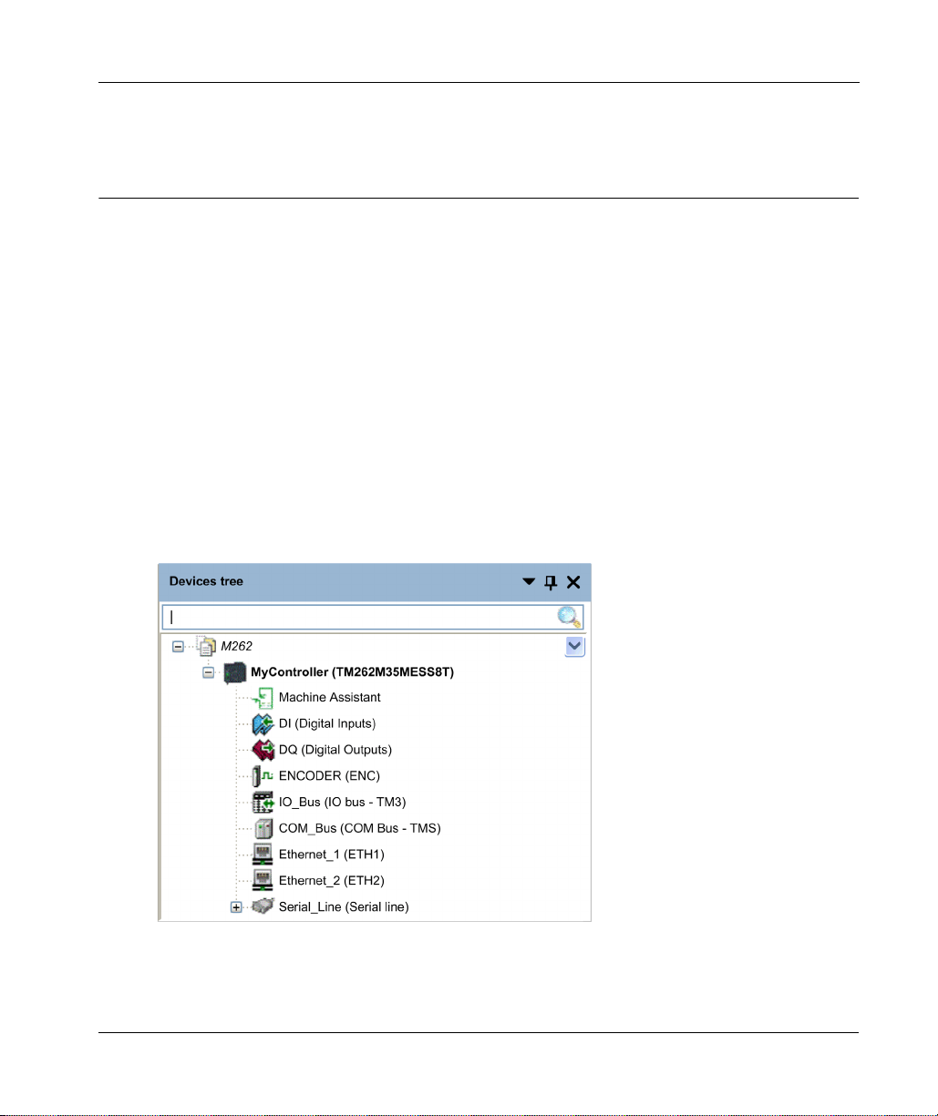
Devices Tree
The Devices tree presents a structured view of the current hardware configuration. When you add
a controller to your project, a number of nodes are added to the Devices tree, depending on the
functions the controller provides.
EIO0000003651 05/2020 21
Page 22

How to Configure the Controller
Item Use to Configure...
Machine Assistant Devices discovery and configuration
DI Embedded digital inputs of the controller
DQ Embedded digital outputs of the controller
ENCODER Incremental or SSI Encoder interface of the controller
IO_Bus Expansion modules connected to the controller
COM_Bus Communication modules connected to the controller
Ethernet_1 Embedded Ethernet dedicated to Motion Bus Sercos on TM262M•, dedicated
Ethernet_2 Embedded Ethernet communication
Serial_Line Serial line communication interface
Applications Tree
The Applications tree allows you to manage project-specific applications as well as global
applications, POUs, and tasks.
Tools Tree
The Tools tree allows you to configure the HMI part of your project and to manage libraries.
The Tools tree allows you to:
Configure the HMI part of your project.
Access to the Library Manager tool.
Access to the Message logger tool
to devices on TM262L•.
(see page 144)
.
22
EIO0000003651 05/2020
Page 23

Modicon M262 Logic/Moti on Controller
Libraries
EIO0000003651 05/2020
Libraries
Chapter 4
Libraries
Libraries
Introduction
Libraries provide functions, function blocks, data types and global variables that can be used to
develop your project.
The Library Manager of EcoStruxure Machine Expert provides information about the libraries
included in your project and allows you to install new ones. For more information on the Library
Manager, refer to the Functions and Libraries User Guide.
Modicon M262 Logic/Motion Controller
When you select a Modicon M262 Logic/Motion Controller for your application, EcoStruxure
Machine Expert automatically loads the following libraries:
Library name Description
IoStandard Standard library for the IO-configuration. This library provides the basic I/O
interface for every IEC I/O driver.
Standard Contains functions and function blocks which are required matching IEC61131-3
as standard POUs for an IEC programming system. Link the standard POUs to
the project (standard.library).
Util Analog Monitors, BCD Conversions, Bit/Byte Functions, Controller Datatypes,
Function Manipulators, Mathematical Functions, Signals.
SE_PLCCommunication Contains communication functions. Most of them are dedicated to Modbus
exchange. Communication functions are processed asynchronously with regard
to the application task that called the function.
SE_M262 PLCSystem Contains functions and variables to get diagnostic information and send
SE_Relocation Table
(see page 36)
M262 Encoder Contains function blocks and enumerated types for enable, monitor and preset of
TM3System Contains functions and function blocks for TM3 expansion modules.
TMSSystem Contains the function block and enumerated types for TMS expansion modules.
EIO0000003651 05/2020 23
commands to the controller system.
Allows you to optimize exchanges between the Modbus client and the controller,
by regrouping non-contiguous data into a contiguous table of registers.
the encoder, capture of the encoder value in incremental or SSI mode, and read
of the active values of the scaling parameters used to compute the unit value.
Page 24

Libraries
24
EIO0000003651 05/2020
Page 25

Modicon M262 Logic/Moti on Controller
Supported Standard Data Types
EIO0000003651 05/2020
Supported Standard Data Types
Chapter 5
Supported Standard Data Types
Supported Standard Data Types
Supported Standard Data Types
The controller supports the following IEC data types:
Data Type Lower Limit Upper Limit Information Content
BOOL FALSE TRUE 1 Bit
BYTE 0 255 8 Bit
WORD 0 65,535 16 Bit
DWORD 0 4,294,967,295 32 Bit
LWORD 0
64
-1
2
SINT -128 127 8 Bit
USINT 0 255 8 Bit
INT -32,768 32,767 16 Bit
UINT 0 65,535 16 Bit
DINT -2,147,483,648 2,147,483,647 32 Bit
UDINT 0 4,294,967,295 32 Bit
LINT
ULINT 0
63
-2
263-1
64
2
-1
REAL 1.175494351e-38 3.402823466e+38 32 Bit
LREAL 2.2250738585072014e-308 1.7976931348623158e+308 64 Bit
STRING 1 character – 1 character = 1 byte
WSTRING 1 character – 1 character = 1 word
TIME - – 32 Bit
64 Bit
64 Bit
64 Bit
For more information on ARRAY, LTIME, DATE, TIME, DATE_AND_TIME, and TIME_OF_DAY, refer
to the EcoStruxure Machine Expert Programming Guide.
EIO0000003651 05/2020 25
Page 26

Supported Standard Data Types
26
EIO0000003651 05/2020
Page 27

Modicon M262 Logic/Moti on Controller
Memory Mapping
EIO0000003651 05/2020
Memory Mapping
Chapter 6
Memory Mapping
Introduction
This chapter describes the memory maps and sizes of the different memory areas in the Modicon
M262 Logic/Motion Controller. These memory areas are used to store user program logic, data and
the programming libraries.
What Is in This Chapter?
This chapter contains the following topics:
Controller Memory Organization 28
Flash Memory Organization 30
RAM Memory Organization 33
NVRAM Memory Organization 35
Relocation Table 36
Topic Page
EIO0000003651 05/2020 27
Page 28
Memory Mapping
Controller Memory Organization
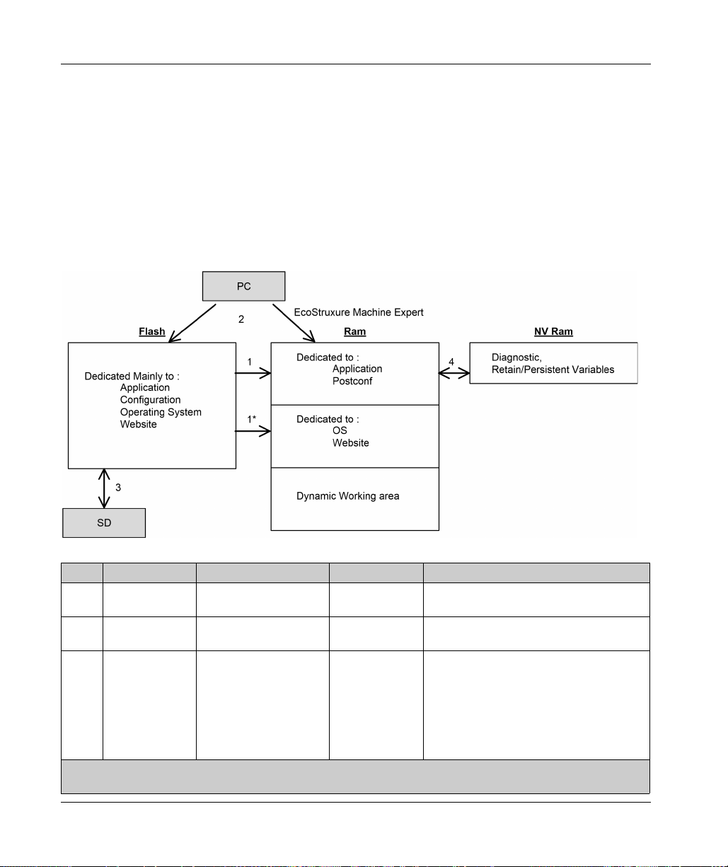
Introduction
The controller memory is composed of three types of physical memory:
The Flash memory
The Random Access Memory (RAM) is used for application execution.
The Non-Volatile Random Access Memory (NVRAM) is used to save the retain-persistent
variables and diagnostic information.
Files Transfers in Memory
(see page 30)
contains files (application, configuration files, and so on).
Item Controller State File Transfer Events Connection Description
1 – Initiated automatically at
1* – Initiated automatically at
2 All states except
INVALID_OS
Power ON and Reboot
Power ON and Reboot
Initiated by user Ethernet or USB
(1)
Internal Files transfer from Flash memory to RAM.
Internal Operating system files transfer.
programming
port
The content of the RAM is overwritten.
Files can be transferred via:
Web server
FTP server
Controller Assistant
EcoStruxure Machine Expert
(see page 125)
(see page 155)
(see EcoStruxure Machine Expert,
Programming Guide)
(1) If the controller is in the INVALID_OS state, the only accessible memory is the SD card and only for firmware
upgrades.
28
EIO0000003651 05/2020
Page 29

Memory Mapping
Item Controller State File Transfer Events Connection Description
3 All states Initiated automatically by
SD card
Up/download with SD card
(1)
.
script (data transfer) or
by power cycle (cloning)
when an SD card is
inserted
4 All states Initiated by system Internal Save of modified retain-persistent variables
and the context on power OFF.
(1) If the controller is in the INVALID_OS state, the only accessible memory is the SD card and only for firmware
upgrades.
NOTE: The modification of files in Flash memory does not affect a running application. Any
changes to files in Flash memory are taken into account at the next reboot, except for the user files
directly used by the application.
EIO0000003651 05/2020 29
Page 30

Memory Mapping
Flash Memory Organization
Introduction
The Flash memory contains the file system used by the controller.
File Type
The Modicon M262 Logic/Motion Controller manages the following file types:
System function (/sys) Description
Operating System (OS) Controller firmware that can be written to Flash memory. The firmware file is
User functions (/usr) Description
Boot application This file resides in Flash memory and contains the compiled binary code of the
executable application. Each time the controller is rebooted, the executable application
is extracted from the boot application and copied into the controller RAM
Application source Source file that can be uploaded from Flash memory to the PC if the source file is not
available on the PC
Post configuration File that contains Ethernet and serial line parameters.
The parameters specified in the file override the parameters in the executable
application at each reset.
Firewall parameters Settings used to configure the firewall of the M262 Logic/Motion Controller. These
settings restrict access to authorized personnel and protocols only. See Firewall
Configuration
Data logging Files in which the controller logs events as specified by the application.
(1) The creation of a boot application is optional in EcoStruxure Machine Expert, according to application
properties. Default option is to create the boot application on download. When you download an
application from EcoStruxure Machine Expert to the controller, you are transferring only the binary
executable application directly to RAM.
(2) EcoStruxure Machine Expert does not support uploading of either the executable application or the boot
application to a PC for modification. Program modifications must be made to the application source. When
you download your application, you have the option to store the source file to Flash memory.
applied at next reboot of the controller.
(2)
.
(see page 187)
for more information.
(1)
.
30
EIO0000003651 05/2020
Page 31

Memory Mapping
File Organization
This table shows the file organization of the flash memory:
Disk Directory File Content Up/Downloaded
data type
/sys Pkg Temporary file Internal use N/A
/usr App Application.app Boot application Application
Application.crc –
Cfg
/usr Log
Archive.prj
Machine.cfg
CodesysLateConf.cfg Name of application to launch. Configuration
FirewallDefault.cmd Default firewall settings. By default, this
(1)
(1)
UserDefinedLogName_1
Application source –
Post configuration file
file does not exist. It can be added
optionally.
.log All *.log files created using the data
logging functions
(see page 253)
(see EcoStruxure
Configuration
Configuration
log file
Machine Expert, Data Logging
Functions, DataLogging Library Guide)
You must specify the total number of
files created and the names and
contents of each log file using the
datalogging feature.
... – –
UserDefinedLogName_n
pki – Certificate store for M262 secured
Rcp – Main directory for Recipes. –
Syslog
Visu – Used for the Webvisualization feature. –
/sd0 – – SD card. Refer to Managing Script Files
– User files – –
(1) If the files had been created due to specific events or customer requirements.
crash.txt
LoggerFile_xxx.mel
(1)
.log – –
protocols.
Record of detected system errors. For
use by Schneider Electric Technical
Support.
(see page 273)
.
.
–
Log file
–
NOTE: For more information on libraries and available function blocks, refer to Libraries
(see page 23)
EIO0000003651 05/2020 31
.
Page 32

Memory Mapping
Files Redirection
When system, program or certain user activity creates specific file types, the M262 Logic/Motion
Controller examines the file extension and automatically moves the file to a corresponding folder
in flash memory.
The following table lists the file types that are moved in this way and the destination folder in flash
memory:
File extensions Flash memory folder
*.app, *.ap_, *.err, *.crc, *.frc, *.prj /usr/App
*.cfg, *.cf_ /usr/Cfg
*.log /usr/Log
*.rcp, *.rsi /usr/Rcp
Backup Data Logging File
Data logging files can become large to the point of exceeding the space available in the file system.
Therefore, you should develop a method to archive the log data periodically on an SD card. You
could split the log data into several files, for example LogMonth1, LogMonth2, and use the
ExecuteScript command to copy the first file to an SD card. Afterwards, you may remove it from
the internal file system while the second file is accumulating data. If you allow the data logging file
to grow and exceed the limits of the file size, you could lose data.
32
NOTICE
LOSS OF APPLICATION DATA
Backup SD card data regularly.
Do not remove power or reset the controller, and do not insert or remove the SD card while it
is being accessed.
Failure to follow these instructions can result in equipment damage.
EIO0000003651 05/2020
Page 33

RAM Memory Organization
Introduction
This section describes the Random Access Memory (RAM) size for different areas of the Modicon
M262 Logic/Motion Controller.
Memory Mapping
The RAM is composed of two areas:
Dedicated application memory
OS memory
This table describes the dedicated application memory:
Area Element
System area System Area Mappable Addresses
%MW0...%MW59999
System and diagnostic variables
(%MW60000...%MW60199)
This memory is accessible through Modbus requests only.
These must be read-only requests.
Dynamic Memory Area: Read Relocation Table
(%MW60200...%MW61999)
This memory is accessible through Modbus requests only.
These must be read-only requests.
System and diagnostic variables
(%MW62000...%MW62199)
This memory is accessible through Modbus requests only.
These can be read or write requests.
Dynamic Memory Area: Write Relocation Table
(%MW62200...%MW63999)
This memory is accessible through Modbus requests only.
These can be read or write requests.
User area Symbols
Variables
Libraries
Application
(see page 36)
(see page 36)
Memory Mapping
EIO0000003651 05/2020 33
Page 34

Memory Mapping
System and Diagnostic Variables
Variables Description
PLC_R Structure of controller read-only system variables.
PLC_W Structure of controller read/write system variables.
ETH_R Structure of Ethernet read-only system variables (Ethernet counters).
ETH_W Structure of Ethernet read/write system variables. Allows you to reset
SERIAL_R Structure of Serial Line read-only system variables (Serial Line counters).
SERIAL_W Structure of Serial Line read-write system variables. Allows you to reset
TM3_MODULE_R Structure of TM3 modules read-only system variables.
TM3_BUS_W Structure of TM3 modules read-write system variables.
TMS_BUS_DIAG_R Structure of TMS modules read-only system variables (diagnostic).
TMS_MODULE_DIAG_R Structure of TMS modules read-only system variables (diagnostic).
Ethernet counters.
Serial Line counters.
For more information on system and diagnostic variables, refer to the M262 System Library Guide
(see Modicon M262 Logic/Motion Controller, System Functions and Variables, System Library
.
Guide)
34
EIO0000003651 05/2020
Page 35

NVRAM Memory Organization
Introduction
The NVRAM memory contains:
Files saved for the diagnostics
Remanent (retain-persistent) variables
NVRAM size
The following table describes the size of the NVRAM:
User Function Description Size
System diagnostics Contain the controller context saved on power off. 128 Kbytes
Remanent (retain-persistent)
variables
Remanent or retain-persistent variables are saved in the NVRAM. Each subsequent read/write
access to these variables requires a NVRAM access. For more information about remanent
variables, see Remanent Variables
performance, see Processing Performance
NOTE: For an optimum cycle time, only access the retain-persistent variables when necessary. For
frequent (Read) access, copy theses variables to a working memory in the RAM.
Modified and saved in the NVRAM.
Saved after each modification. This action impacts
the cycle time.
(see page 71)
. For more information about the impact on
(seepage313)
.
Memory Mapping
Retain: 64 Kbytes
Persistent: 64 Kbytes
EIO0000003651 05/2020 35
Page 36

Memory Mapping
Relocation Table
Introduction
The Relocation Table allows you to organize data to optimize communication between the
controller and other equipment by regrouping non-contiguous data into a contiguous table of
located registers, accessible through Modbus.
NOTE: A relocation table is considered an object. Only one relocation table object can be added
to a controller.
Relocation Table Description
This table describes the Relocation Table organization:
Register Description
60200...61999 Dynamic Memory Area: Read Relocation Table
62200...63999 Dynamic Memory Area: Write Relocation Table
For further information, refer to M262 System Library Guide.
Adding a Relocation Table
This table describes how to add a Relocation Table to your project:
The %MW registers are read from the variables at each cycle.
The %MW registers are copied to the variables at each cycle.
36
Step Action
1 In the Applications tree tab, select the Application node.
2 Click the right mouse button.
3 Click Objects → Relocation Table....
Result: The Add Relocation Table window is displayed.
4 Click Add.
Result: The new relocation table is created and initialized.
NOTE: As a Relocation Table is unique for a controller, its name is Relocation Table and cannot
be changed.
EIO0000003651 05/2020
Page 37

Relocation Table Editor
The relocation table editor allows you to organize your variables in the relocation table.
To access the relocation table editor, double-click the Relocation Table node in the Tools tree tab:
This picture describes the relocation table editor:
Memory Mapping
EIO0000003651 05/2020 37
Page 38

Memory Mapping
Icon Element Description
- ID Automatic incremental integer (not editable).
- Variable The name or the full path of a variable (editable).
- Address The address of the system area where the variable is stored (not editable).
- Length Variable length in word.
- Validity Indicates if the entered variable is valid (not editable).
New Item Adds an element to the list of system variables.
Move Down Moves down the selected element of the list.
Move Up Moves up the selected element of the list.
Delete Item Removes the selected elements of the list.
Copy Copies the selected elements of the list.
Paste Pastes the elements copied.
Erase Empty Item Removes all the elements of the list for which the "Variable" column is empty.
38
NOTE: If a variable is undefined after program modifications, the content of the cell is displayed in
red, the related Validity cell is False, and Address is set to -1.
EIO0000003651 05/2020
Page 39

Modicon M262 Logic/Moti on Controller
Tasks
EIO0000003651 05/2020
Tasks
Chapter 7
Tasks
Introduction
The Task Configuration node in the Applications tree allows you to define one or more tasks to
control the execution of your application program.
The task types available are:
Cyclic
Freewheeling
Event
External event
This chapter begins with an explanation of these task types and provides information regarding the
maximum number of tasks, the default task configuration, and task prioritization. In addition, this
chapter introduces the system and task watchdog functions and explains its relationship to task
execution.
What Is in This Chapter?
This chapter contains the following topics:
Topic Page
Maximum Number of Tasks 40
Task Types 41
Task Configuration Screen 45
System and Task Watchdogs 47
Task Priorities 48
Default Task Configuration 50
EIO0000003651 05/2020 39
Page 40

Tasks
Maximum Number of Tasks
Maximum Number of Tasks
The maximum number of tasks you can define for the Modicon M262 Logic/Motion Controller are:
Total number of tasks = 16
Cyclic tasks = 8
Freewheeling tasks = 1
Event tasks = 8
External Event tasks = 8
Special Considerations for Freewheeling
A Freewheeling task
scan starts when the previous scan has been completed and after a period of system processing
(30% of the total duration of the Freewheeling task). If the system processing period is reduced to
less than 15% for more than 3 seconds due to interruptions by other tasks, a system error is
detected. For more information, refer to the System Watchdog
Controller, Programming Guide)
NOTE: You may wish to avoid using a Freewheeling task in a multi-task application when some
high priority and time-consuming tasks are running. Doing so may provoke a task Watchdog
Timeout. You should not assign CANopen to a freewheeling task. CANopen should be assigned
to a cyclic task.
(see page 42)
does not have a fixed duration. In Freewheeling mode, the task
(see Modicon LMC078, Motion
.
40
EIO0000003651 05/2020
Page 41

Task Types
Introduction
The following section describes the various task types available for your program, along with a
description of the task type characteristics.
Cyclic Task
A Cyclic task is assigned a fixed cycle time using the Interval setting in the Type section of
Configuration subtab for that task. Each Cyclic task type executes as follows:
1. Read Inputs: The physical input states are written to the %I input memory variables and other
system operations are executed.
2. Task Processing: The user code (POU, and so on) defined in the task is processed. The %Q
output memory variables are updated according to your application program instructions but not
yet written to the physical outputs during this operation.
3. Write Outputs: The %Q output memory variables are modified with any output forcing that has
been defined; however, the writing of the physical outputs depends upon the type of output and
instructions used.
For more information on defining the bus cycle task, refer to the EcoStruxure Machine Expert
Programming Guide and Modicon M262 Logic/Motion Controller Settings
For more information on I/O behavior, refer to Controller States Detailed Description
(see page 56)
4. Remaining Interval time: The controller firmware carries out system processing and any other
lower priority tasks.
NOTE: If you define too short a period for a cyclic task, it will repeat immediately after the write of
the outputs and without executing other lower priority tasks or any system processing. This will
affect the execution of all tasks and cause the controller to exceed the system watchdog limits,
generating a system watchdog exception.
Tasks
(see page 77)
.
.
EIO0000003651 05/2020 41
Page 42

Tasks
Freewheeling Task
A Freewheeling task does not have a fixed duration. In Freewheeling mode, each task scan begins
when the previous scan has been completed and after a short period of system processing. Each
Freewheeling task type executes as follows:
1. Read Inputs: The physical input states are written to the %I input memory variables and other
system operations are executed.
2. Task Processing: The user code (POU, and so on) defined in the task is processed. The %Q
output memory variables are updated according to your application program instructions but not
yet written to the physical outputs during this operation.
3. Write Outputs: The %Q output memory variables are modified with any output forcing that has
been defined; however, the writing of the physical outputs depends upon the type of output and
instructions used.
For more information on defining the bus cycle task, refer to the EcoStruxure Machine Expert
Programming Guide and Modicon M262 Logic/Motion Controller Settings
For more information on I/O behavior, refer to Controller States Detailed Description
(see page 56)
4. System Processing: The controller firmware carries out system processing and any other lower
priority tasks (for example: HTTP management, Ethernet management, parameters
management).
NOTE: If you want to define the task interval, refer to Cyclic Task
(see page 77)
.
.
(see page 41)
.
42
EIO0000003651 05/2020
Page 43

Event Task
This type of task is event-driven and is initiated by a program variable. It starts at the rising edge
of the boolean variable associated to the trigger event unless pre-empted by a higher priority task.
In that case, the Event task will start as dictated by the task priority assignments.
For example, if you have defined a variable called my_Var and would like to assign it to an Event,
proceed as follows:
Step Action
NOTE: When the event task is triggered with too high a frequency, the controller may detect an
error and transition to the HALT state (Exception). The maximum rate of events is 10 events per
millisecond for TM262L10MESE8T and TM262M15MESS8T, and 16 events per millisecond for
TM262L20MESE8T, TM262M25MESS8T and TM262M35MESS8T. If the event task is triggered
at a higher frequency than this, the message 'ISR Count Exceeded' is logged in the application log
page.
Tasks
1 Double-click the TASK in the Applications tree.
2 Select Event from the Type list in the Configuration tab.
3
Click the Input Assistant button to the right of the Event field.
Result: The Input Assistant window appears.
4 Navigate in the tree of the Input Assistant dialog box to find and assign the my_Var variable.
EIO0000003651 05/2020 43
Page 44

Tasks
External Event Task
This type of task is event-driven and is initiated by the detection of a hardware or hardware-related
function event. It starts when the event occurs unless pre-empted by a higher priority task. In that
case, the External Event task will start as dictated by the task priority assignments.
For example, an External event task could be associated with an HSC Stop event. To associate
the HSC0_STOP event to an External event task, select it from the External event drop-down list
on the Configuration tab.
The external event task can be associated with the CAN Sync event. To associate the
CAN_1_SYNC event to an external event task, select it from the External event dropdown list in
the Configuration tab.
Different types of events can be associated with an External event task:
HSC thresholds
HSC Stop
CAN Sync
HSC Event Periodmeter
Event input
NOTE: CAN Sync is a specific event object, depending on the CANopen manager configuration.
NOTE: When the external event task is triggered with too high a frequency, the controller may
detect an error and transition to the HALT state (Exception). The maximum rate of events is
10 events per millisecond for TM262L10MESE8T and TM262M15MESS8T, and 16 events per
millisecond for TM262L20MESE8T, TM262M25MESS8T and TM262M35MESS8T. If the event
task is triggered at a higher frequency than this, the message 'ISR Count Exceeded' is logged in
the application log page.
(see Modicon TM3 Expert I/O Modules, HSC Library Guide)
44
EIO0000003651 05/2020
Page 45

Task Configuration Screen
Screen Description
This screen allows you to configure the tasks. Double-click the task that you want to configure in
the Applications tree to access this screen.
Each configuration task has its own parameters that are independent of the other tasks.
The Configuration window is composed of four parts:
Tasks
EIO0000003651 05/2020 45
Page 46

Tasks
The table describes the fields of the Configuration screen:
Field Name Definition
Priority Configure the priority of each task with a number from 0 to 31 (0 is the highest priority, 31 is
the lowest).
Only one task at a time can be running. The priority determines when the task runs:
A higher priority task pre-empts a lower priority task
Tasks with same priority run in turn (2 ms time-slice)
NOTE: Do not assign tasks with the same priority. If there are yet other tasks that attempt
to pre-empt tasks with the same priority, the result could be indeterminate and unpredicable.
For important safety information, refer to Task Priorities
(see page 48)
.
Type These task types are available:
Cyclic
Event
External
Freewheeling
Watchdog To configure the watchdog
(see page 41)
(see page 43)
(see page 44)
(see page 42)
(see Modicon LMC078, Motion Controller, Programming Guide)
define these two parameters:
Time: enter the timeout before watchdog execution.
Sensitivity: defines the number of expirations of the watchdog timer before the controller
stops program execution and enters a HALT state.
POUs The list of Programming Organization Units (POUs) controlled by the task is defined in the
task configuration window
To add a POU linked to the task, use the command Add Call and select the POU in the
(see EcoStruxure Machine Expert, Programming Guide)
:
Input Assistant editor.
To remove a POU from the list, use the command Remove Call.
To replace the currently selected POU of the list by another one, use the command
Change Call.
POUs are executed in the order shown in the list. To move the POUs in the list, select a
POU and use the command Move Up or Move Down.
NOTE: You can create as many POUs as you want. An application with several small
POUs, as opposed to one large POU, can improve the refresh time of the variables in online
mode.
,
46
EIO0000003651 05/2020
Page 47

System and Task Watchdogs
Introduction
Two types of watchdog functionality are implemented for the Modicon M262 Logic/Motion
Controller:
System Watchdogs: These watchdogs are managed by the controller firmware. You cannot
configure them.
Task Watchdogs: These watchdogs are optional watchdogs that you can define for each task.
These are configurable in EcoStruxure Machine Expert.
System Watchdogs
Three system watchdogs are defined for the Modicon M262 Logic/Motion Controller. They are
managed by the controller firmware and are therefore sometimes referred to as hardware
watchdogs in the EcoStruxure Machine Expert online help. When one of the system watchdogs
exceeds its threshold conditions, an error is detected.
The threshold conditions for the three system watchdogs are defined as follows:
If all of the tasks require more than 85% of the processor resources for more than 3 seconds, a
system error is detected. The controller enters the HALT state.
If the total execution time of the tasks with priorities between 0 and 24 reaches 100% of
processor resources for more than 1 second, an application error is detected. The controller
responds with an automatic reboot into the EMPTY state.
If the lowest priority task of the system is not executed during an interval of 10 seconds, a
system error is detected. The controller responds with an automatic reboot into the EMPTY
state.
NOTE: You cannot configure the system watchdogs.
Tasks
Task Watchdogs
EcoStruxure Machine Expert allows you to configure an optional task watchdog for every task
defined in your application program. (Task watchdogs are sometimes also referred to as software
watchdogs or control timers in the EcoStruxure Machine Expert online help). When one of your
defined task watchdogs reaches its threshold condition, an application error is detected and the
controller enters the HALT state.
When defining a task watchdog, the following options are available:
Time: This defines the allowable maximum execution time for a task. When a task takes longer
than this, the controller reports a task watchdog exception.
Sensitivity: The sensitivity field defines the number of task watchdog exceptions that must occur
before the controller detects an application error.
To access the configuration of a task watchdog, double-click the Task in the Applications tree.
NOTE: For more information on watchdogs, refer to EcoStruxure Machine Expert Programming
Guide.
EIO0000003651 05/2020 47
Page 48

Tasks
Task Priorities
Task Priority Configuration
You can configure the priority of each task between 0 and 31 (0 is the highest priority, 31 is the
lowest). Each task must have a unique priority. Assigning the same priority to more than one task
leads to a build error.
Task Priority Suggestions
Priority 0 to 24: Controller tasks. Assign these priorities to tasks with a high availability
requirement.
Priority 25 to 31: Background tasks. Assign these priorities to tasks with a low availability
requirement.
Task Priorities of Embedded I/Os
When a task cycle starts, it can interrupt any task with lower priority (task preemption). The
interrupted task resumes when the higher priority task cycle is finished.
48
EIO0000003651 05/2020
Page 49

NOTE: If the same input is used in different tasks the input image may change during the task cycle
of the lower priority task.
To improve the likelihood of proper output behavior during multitasking, a build error message is
displayed if outputs in the same byte are used in different tasks.
UNINTENDED EQUIPMENT OPERATION
Map your inputs so that tasks do not alter the input images in an unexpected manner.
Failure to follow these instructions can result in death, serious injury, or equipment damage.
Task Priorities of TM3 Modules and CANopen I/Os
You can select the task that drives TM3 I/Os and CANopen physical exchanges. In the PLC
settings, select Bus cycle task to define the task for the exchange. By default, the task is set to
MAST. This definition at the controller level can be overridden by the I/O bus configuration
(see page 106)
TM3 and CANopen data is copied into a virtual I/O image during a physical exchanges phase, as
shown in this figure:
Inputs are read from the I/O image table at the beginning of the task cycle. Outputs are written to
the I/O image table at the end of the task.
NOTE: TM3 influence the application execution time. You can configure the Bus cycle options
using I/O mapping tab. Refer to the TM3 Expansion Modules Programming Guide.
. D urin g th e rea d and write phas es, a ll ph ysic al I/O s are ref reshed at the same time.
Tasks
WARNING
EIO0000003651 05/2020 49
Page 50

Tasks
Default Task Configuration
Default Task Configuration
The MAST task can be configured in Freewheeling or Cyclic mode. The MAST task is automatically
created by default in Cyclic mode. Its preset priority is medium (15), its preset interval is 10 ms,
and its task watchdog service is activated with a time of 50 ms and a sensitivity of 1. Refer to Task
Priorities
information on watchdogs.
Designing an efficient application program is important in systems approaching the maximum
number of tasks. In such an application, it can be difficult to keep the resource utilization below the
system watchdog threshold. If priority reassignments alone are not sufficient to remain below the
threshold, some lower priority tasks can be made to use fewer system resources if the
SysTaskWaitSleep function, contained in the SysTask library, is added to those tasks.
NOTE: Do not delete or change the name of the MAST task. Otherwise, EcoStruxure Machine
Expert detects an error when you attempt to build the application, and you are not able to download
it to the controller.
(see page 48)
for more information on priority settings. Refer to Task Watchdogs for more
50
EIO0000003651 05/2020
Page 51

Modicon M262 Logic/Moti on Controller
Controller States and Behaviors
EIO0000003651 05/2020
Controller States and Behaviors
Chapter 8
Controller States and Behaviors
Introduction
This chapter provides you with information on controller states, state transitions, and behaviors in
response to system events. It begins with a detailed controller state diagram and a description of
each state. It then defines the relationship of output states to controller states before explaining the
commands and events that result in state transitions. It concludes with information about
Remanent variables and the effect of EcoStruxure Machine Expert task programming options on
the behavior of your system.
What Is in This Chapter?
This chapter contains the following sections:
Section Topic Page
8.1 Controller State Diagram 52
8.2 Controller States Description 56
8.3 State Transitions and System Events 60
EIO0000003651 05/2020 51
Page 52

Controller States and Behaviors
Controller State Diagram
Section 8.1
Controller State Diagram
Controller State Diagram
Controller State Diagram
This diagram describes the controller operating mode:
52
ALL-CAPS BOLD: Controller states
Bold: User and application commands
Italics
: System events
Normal text: Decisions, decision results, and general information
(1) For details on STOPPED to RUNNING state transition, refer to Run Command
(2) For details on RUNNING to STOPPED state transition, refer to Stop Command
EIO0000003651 05/2020
(see page 64)
(see page 64)
.
.
Page 53

Note 1
Note 2
Note 3
Note 4
Controller States and Behaviors
The alarm relay is open.
The outputs assume their hardware initialization states. The encoder power supply is not enabled.
The voltage is 0. The alarm relay is closed.
In some cases, when a system error is detected, it causes the controller to reboot automatically
into the EMPTY state as if no Boot application were present in the Flash memory. However, the
Boot application is not deleted from the Flash memory. In this case, the ERR LED (Red) flashes
fast and regularly.
After verification of a valid Boot application the following events occur:
The application is loaded into RAM.
The Post Configuration
(see page 253)
file settings (if any) are applied.
During the load of the boot application, a Check context test occurs to assure that the Remanent
variables are valid. If the Check context test is invalid, the boot application loads but the controller
assumes STOPPED state
(see page 67)
.
Note 5a
The Starting Mode is set in the PLC settings tab of the Controller Device Editor
(seepage77)
.
Note 5b
When a power interruption occurs, the controller continues in the RUNNING state for at least 4 ms
before shutting down. If you have configured and provide power to the Run/Stop input from the
same source as the controller, the loss of power to this input is detected immediately, and the
controller behaves as if a STOP command was received. Therefore, if you provide power to the
controller and the Run/Stop input from the same source, your controller reboots normally into the
STOPPED state after a power interruption when Starting Mode is set to Start as previous state.
Note 6
During a successful application download the following events occur:
The application is loaded directly into RAM.
By default, the Boot application is created and saved into the Flash memory.
EIO0000003651 05/2020 53
Page 54

Controller States and Behaviors
Note 7
The default behavior after downloading an application program is for the controller to enter the
STOPPED state irrespective of the Run/Stop input setting, the Run/Stop switch position or the last
controller state before the download.
However, there are two considerations in this regard:
Online Change: An online change (partial download) initiated while the controller is in the
RUNNING state returns the controller to the RUNNING state if successful and provided the
Run/Stop input is configured and set to Run or Run/Stop switch is set to Run. Before using the
Login with online change option, test the changes to your application program in a virtual or nonproduction environment and confirm that the controller and attached equipment assume their
expected conditions in the RUNNING state.
UNINTENDED EQUIPMENT OPERATION
Always verify that online changes to a RUNNING application program operate as expected
before downloading them to controllers.
Failure to follow these instructions can result in death, serious injury, or equipment damage.
NOTE: Online changes to your program are not automatically written to the Boot application,
and are overwritten by the existing Boot application at the next reboot. If you wish your changes
to persist through a reboot, manually update the Boot application by selecting Create boot
application in the online menu (the controller must be in the STOPPED state to achieve this
operation).
Multiple Download: EcoStruxure Machine Expert has a feature that allows you to perform a full
application download to multiple targets on your network or fieldbus. One of the default options
when you select the Multiple Download... command is the Start all applications after download
or online change option, which restarts all download targets in the RUNNING state, provided
their respective Run/Stop inputs are commanding the RUNNING state, but irrespective of their
last controller state before the multiple download was initiated. Deselect this option if you do not
want all targeted controllers to restart in the RUNNING state. In addition, before using the
Multiple Download option, test the changes to your application program in a virtual or nonproduction environment and confirm that the targeted controllers and attached equipment
assume their expected conditions in the RUNNING state.
WARNING
54
WARNING
UNINTENDED EQUIPMENT OPERATION
Always verify that your application program will operate as expected for all targeted controllers
and equipment before issuing the “Multiple Download…” command with the “Start all
applications after download or online change” option selected.
Failure to follow these instructions can result in death, serious injury, or equipment damage.
EIO0000003651 05/2020
Page 55

Note 8
Note 9
Note 10
Controller States and Behaviors
NOTE: During a multiple download, unlike a normal download, EcoStruxure Machine Expert
does not offer the option to create a Boot application. You can manually create a Boot
application at any time by selecting Create boot application in the Online menu on all targeted
controllers.
The EcoStruxure Machine Expert software platform allows many powerful options for managing
task execution and output conditions while the controller is in the STOPPED or HALT states. Refer
to Controller States Description
(see page 56)
for further details.
To exit the HALT state it is necessary to issue one of the Reset commands (Reset Warm, Reset
Cold, Reset Origin), download an application or cycle power.
In case of non-recoverable event (hardware watchdog or internal error), a cycle power is
mandatory.
The RUNNING state has two exception conditions:
RUNNING with External Error: this exception condition is indicated by the I/O LED, which
displays solid Red. You may exit this state by clearing the external error (probably changing the
application configuration). No controller commands are required, but may however include the
need of a power cycle of the controller. For more information, refer to I/O Configuration General
Description
RUNNING with Breakpoint: this exception condition is indicated by the RUN LED, which
(see page 102)
displays a single flash. Refer to Controller States Description
.
(see page 56)
for further details.
Note 11
The boot application can be different from the application loaded. It can happen when the boot
application was downloaded through SD card, FTP, or file transfer or when an online change was
performed without creating the boot application.
EIO0000003651 05/2020 55
Page 56

Controller States and Behaviors
Controller States Description
Section 8.2
Controller States Description
Controller States Description
Introduction
This section provides a detailed description of the controller states.
UNINTENDED EQUIPMENT OPERATION
Never assume that your controller is in a certain controller state before commanding a change
of state, configuring your controller options, uploading a program, or modifying the physical
configuration of the controller and its connected equipment.
Consider the effect of any of these operations on all connected equipment before performing
any of these operations.
Positively confirm the controller state by viewing its LEDs before acting on the controller.
Confirm the condition of the Run/Stop input (if so equipped and configured) and/or the
Run/Stop switch (if so equipped) before acting on the controller.
Verify the presence of output forcing before acting on the controller.
Review the controller status information via EcoStruxure Machine Expert before acting on the
controller.
Failure to follow these instructions can result in death, serious injury, or equipment damage.
(1)
WARNING
56
(1)
The controller states can be read in the PLC_R.i_wStatus system variable of the M262 System
library.
EIO0000003651 05/2020
Page 57

Controller States and Behaviors
Controller States Table
The following tables describe the controller states:
Controller State Description LED Status
BOOTING The controller executes the boot
firmware and its own internal self-tests. It
then verifies the checksum of the
firmware and user applications.
INVALID_OS There is not a valid firmware file present
in the flash memory or the firmware is not
from Schneider Electric. The controller
does not execute the application. Refer
to the Updating Firmware
(see page 261)
section to restore a
correct state.
Controller State Description LED
EMPTY The controller has no application. OFF Single
EMPTY after a
system error
detected
This state is the same as the normal EMPTY state. But the
application is present, and is intentionally not loaded. A next reboot
(power cycle), or a new application download, restores correct state.
RUNNING The controller is executing a valid application. ON OFF OFF
RUNNING with
breakpoint
This state is same as the RUNNING state with the following
exceptions:
The task-processing portion of the program does not resume until
the breakpoint is cleared.
The LED indications are different.
For more information on breakpoint management, refer to
EcoStruxure Machine Expert Programming Guide.
RUNNING with
external error
detected
Configuration, TM3, SD card, or other I/O error detected.
When I/O LED is ON, the details about the detected error can be
found in PLC_R.i_lwSystemFault_1 and
PLC_R.i_lwSystemFault_2. Any of the detected error conditions
reported by these variables cause the I/O LED to be ON.
STOPPED The controller has a valid application that is stopped. See details of
the STOPPED state
(see page 58)
for an explanation of the behavior
of outputs and field buses in this state.
Each LED, from the PWR LED to the NS or S3 LED,
depending on the controller reference, flashes before
turning solid green. The boot sequence is complete
when all the LEDs are solid green. The LEDs then flash
together briefly to indicate that the controller is
operational.
FSP LED stays solid red after the boot sequence.
RUN
(Green)
ERR
(Red)
I/O
(Red)
OFF
flash
OFF Fast
OFF
flash
Single
OFF OFF
flash
ON OFF ON
Regular
OFF OFF
flash
EIO0000003651 05/2020 57
Page 58

Controller States and Behaviors
Controller State Description LED
RUN
(Green)
STOPPED with
external error
detected
HALT The controller stops executing the application because it has
Boot Application
not saved
Configuration, TM3, SD card, or other I/O error detected. Regular
detected an application error
The controller has an application in memory that differs from the
application in Flash memory. At next power cycle, the application is
changed by the one from Flash memory.
flash
Regular
flash
ON or
regular
flash
This figure shows the difference between the fast flash, the regular flash and single flash:
ERR
(Red)
OFF ON
ON –
Single
flash
I/O
(Red)
OFF
Details of the STOPPED State
The following statements are true for the STOPPED state:
The input configured as the Run/Stop input remains operational.
The output configured as the Alarm output remains operational and goes to a value of 0.
Ethernet, Serial (Modbus, ASCII, and so on), and USB communication services remain
operational and commands written by these services can continue to affect the application, the
controller state, and the memory variables.
Web visualization is not operational.
Outputs initially assume their configured default state (Keep current values or Set all outputs to
default) or the state dictated by output forcing if used. The subsequent state of the outputs
depends on the value of the Update IO while in stop setting and on commands received from
remote devices. For more information on the behavior of the TM3 outputs, refer to Modicon TM3
Expansion Modules Configuration - Programming Guide
Modules, Programming Guide)
58
(see Modicon TM3, Expansion
.
EIO0000003651 05/2020
Page 59

Controller States and Behaviors
Task and I/O Behavior When Update IO While In Stop Is Selected
When the Update IO while in stop setting is selected:
The Read Inputs operation continues normally. The physical input s are re ad and th en writ t en
to the %I input memory variables.
The Task Processing operation is not executed.
The Write Outputs operation continues. The %Q output memory variables are updated to
reflect either the Keep current values configuration or the Set all outputs to default
configuration, adjusted for any output forcing, and then written to the physical outputs.
CANopen Behavior When Update IO While In Stop Is Selected
The following is true for the CANopen buses when the Update IO while in stop setting is
selected:
The CANopen bus remains fully operational. Devices on the CANopen bus continue to
perceive the presence of a functional CANopen Master.
TPDO and RPDO continue to be exchanged.
The optional SDO, if configured, continue to be exchanged.
The Heartbeat and Node Guarding functions, if configured, continue to operate.
If the Behaviour for outputs in Stop field is set to Keep current values, the TPDOs continue
to be issued with the last actual values.
If the Behaviour for outputs in Stop field is Set all outputs to default the last actual values are
updated to the default values and subsequent TPDOs are issued with these default values.
Task and I/O Behavior When Update IO While In Stop Is Not Selected
When the Update IO while in stop setting is not selected, the controller sets the I/O to either the
Keep current values or Set all outputs to default condition (as adjusted for output forcing if used).
After this, the following becomes true:
The Read Inputs operation ceases. The %I input memory variables are frozen at their last
values.
The Task Processing operation is not executed.
The Write Outputs operation ceases. The %Q output memory variables can be updated via
the Ethernet, Serial, and USB connections. However, the physical outputs are unaffected
and retain the state specified by the configuration options.
CANopen Behavior When Update IO While In Stop Is Not Selected
The following is true for the CANopen buses when the Update IO while in stop setting is not
selected:
The CANopen Master ceases communications. Devices on the CANopen bus assume their
configured fallback states.
TPDO and RPDO exchanges cease.
Optional SDO, if configured, exchanges cease.
The Heartbeat and Node Guarding functions, if configured, stop.
The current or default values, as appropriate, are written to the TPDOs and sent once before
stopping the CANopen Master.
EIO0000003651 05/2020 59
Page 60

Controller States and Behaviors
State Transitions and System Events
Section 8.3
State Transitions and System Events
Overview
This section begins with an explanation of the output states possible for the controller. It then
presents the system commands used to transition between controller states and the system events
that can also affect these states. It concludes with an explanation of the Remanent variables, and
the circumstances under which different variables and data types are retained through state
transitions.
What Is in This Section?
This section contains the following topics:
Controller States and Output Behavior 61
Commanding State Transitions 64
Error Detection, Types, and Management 70
Remanent Variables 71
Topic Page
60
EIO0000003651 05/2020
Page 61

Controller States and Output Behavior
Introduction
The Modicon M262 Logic/Motion Controller defines output behavior in response to commands and
system events in a way that allows for greater flexibility. An understanding of this behavior is
necessary before discussing the commands and events that affect controller states. For example,
typical controllers define only two options for output behavior in stop: fallback to default value or
keep current value.
The possible output behaviors and the controller states to which they apply are:
Managed by Application Program
Keep current values
Set all outputs to default
Hardware Initialization Values
Software Initialization Values
Output Forcing
NOTE: For TM3 Expert module reflex output behavior, refer to Modicon TM3 Expansion Modules
Configuration - Programming Guide
Guide)
.
Managed by Application Program
Your application program manages outputs normally. This applies in the RUNNING and RUNNING
with External Error Detected states.
NOTE: An exception to this is if the RUNNING with External Error Detected state has been
provoked by a I/O expansion bus error. For more information, refer to I/O Configuration General
Description
(see page 102)
.
(see Modicon TM3, Expansion Modules, Programming
Controller States and Behaviors
Keep Current Values
Select this option by choosing Controller Editor → PLC settings → Behavior for outputs in Stop →
Keep current values. To access the Controller Editor, right-click on the controller in the device tree
and select Edit Object.
This output behavior applies in the STOPPED controller state. It also applies to CAN bus in the
HALT controller state. Outputs are set to and maintained in their current state, although the details
of the output behavior vary greatly depending on the setting of the Update I/O while in stop option
and the actions commanded via configured fieldbusses. Refer to for more details on these
variations.
EIO0000003651 05/2020 61
Page 62

Controller States and Behaviors
Set All Outputs to Default
Select this option by choosing Controller Editor → PLC settings → Behavior for outputs in Stop →
Set all outputs to default. To access the Controller Editor, right-click on the controller in the device
tree and select Edit Object.
This output behavior applies:
when the controller is going from RUN state to STOPPED state.
if the controller is going from RUN state to HALT state.
after application download.
after reset warm/cold command.
after a reboot.
It also applies to CAN bus in the HALT controller state. Outputs are set to and maintained in their
current state, although the details of the output behavior vary greatly depending on the setting of
the Update I/O while in stop option and the actions commanded via configured fieldbusses.Refer
to Controller States Description
Hardware Initialization Values
This output state applies in the BOOTING, EMPTY (following power cycle with no boot application
or after the detection of a system error), and INVALID_OS states.
In the initialization state, analog, transistor, and relay outputs assume the following values:
For an analog output: Z (high impedance)
For a fast transistor output: Z (high impedance)
For a regular transistor output: 0 Vdc
For a relay output: Open
(see page 56)
for more details on these variations.
Software Initialization Values
This output state applies when downloading or when resetting the application. It applies at the end
of the download or at the end of a reset warm or cold.
The software Initialization Values are the initialization values of outputs images (%I, %Q, or
variables mapped on %I or %Q).
By default, they are set to 0 but it is possible to map the I/O in a GVL and assign to the outputs a
value different than 0.
62
EIO0000003651 05/2020
Page 63

Output Forcing
The controller allows you to force the state of selected outputs to a defined value for the purposes
of system testing, commissioning, and maintenance.
You are only able to force the value of an output while your controller is connected to EcoStruxure
Machine Expert.
To do so, use the Force values command in the Debug menu.
Output forcing overrides all other commands (except write immediate) to an output irrespective of
the task programming that is being executed.
When you logout of EcoStruxure Machine Expert when output forcing has been defined, you are
presented with the option to retain output forcing settings. If you select this option, the output
forcing continues to control the state of the selected outputs until you download an application or
use one of the Reset commands.
When the option Update I/O while in stop, if supported by your controller, is checked (default state),
the forced outputs keep the forcing value even when the logic controller is in STOP.
Output Forcing Considerations
The output you wish to force must be contained in a task that is currently being executed by the
controller. Forcing outputs in unexecuted tasks, or in tasks whose execution is delayed either by
priorities or events has no effect on the output. However, once the task that had been delayed is
executed, the forcing takes effect at that time.
Depending on task execution, the forcing could impact your application in ways that may not be
obvious to you. For example, an event task could turn on an output. Later, you may attempt to turn
off that output but the event is not being triggered at the time. This would have the effect of the
forcing being apparently ignored. Further, at a later time, the event could trigger the task at which
point the forcing would take effect.
In case of any forced variable, the FSP LED is flashing red, regular flash.
Controller States and Behaviors
WARNING
UNINTENDED EQUIPMENT OPERATION
You must have a thorough understanding of how forcing will affect the outputs relative to the
tasks being executed.
Do not attempt to force I/O that is contained in tasks that you are not certain will be executed
in a timely manner, unless your intent is for the forcing to take affect at the next execution of
the task whenever that may be.
If you force an output and there is no apparent affect on the physical output, do not exit
EcoStruxure Machine Expert without removing the forcing.
Failure to follow these instructions can result in death, serious injury, or equipment damage.
EIO0000003651 05/2020 63
Page 64

Controller States and Behaviors
Commanding State Transitions
Run Command
Effect:
Commands a transition to the RUNNING controller state.
Starting Conditions:
Methods for Issuing a Run Command:
Refer to Run/Stop Input
EcoStruxure Machine Expert Online Menu: Select the Start command.
RUN command from Web Server
By an external call via Modbus request using the PLC_W.q_wPLCControl and
PLC_W.q_uiOpenPLCControl system variables of the M262 System library.
Login with online change option: An online change (partial download) initiated while the
controller is in the RUNNING state returns the controller to the RUNNING state if successful.
Multiple Download Command: sets the controllers into the RUNNING state if the Start all
applications after download or online change option is selected, irrespective of whether the
targeted controllers were initially in the RUNNING, STOPPED, HALT, or EMPTY state.
The controller is restarted into the RUNNING state automatically under certain conditions.
Refer to Controller State Diagram
Stop Command
Effect:
Starting Conditions:
Methods for Issuing a Stop Command:
Run/Stop Input: If configured, command a value of 0 to the Run/Stop input. Refer to Run/Stop
Input
EcoStruxure Machine Expert Online Menu: Select the Stop command.
STOP command from WebServer
By an internal call by the application or an external call via Modbus request using the PLC_W.
q_wPLCControl and PLC_W. q_uiOpenPLCControl system variables of the M262 System
library.
Login with online change option: An online change (partial download) initiated while the
controller is in the STOPPED state returns the controller to the STOPPED state if successful.
Download Command: implicitly sets the controller into the STOPPED state.
Multiple Download Command: sets the controllers into the STOPPED state if the Start all
applications after download or online change option is not selected, irrespective of whether the
targeted controllers were initially in the RUNNING, STOPPED, HALT, or EMPTY state.
REBOOT by Script: The file transfer script on an SD card can issue a REBOOT as its final
command. The controller is rebooted into the STOPPED state provided the other conditions of
the boot sequence allow this to occur. Refer to Reboot
The controller is restarted into the STOPPED state automatically under certain conditions.
Refer to Controller State Diagram
Commands a transition to the STOPPED controller state.
(see page 91)
BOOTING or STOPPED state.
(see page 91)
BOOTING, EMPTY, or RUNNING state.
for more information.
for more information.
(see page 52)
(see page 52)
for further details.
(see page 67)
for further details.
for further details.
64
EIO0000003651 05/2020
Page 65

Reset Warm
Effect:
controller into the STOPPED state.
Starting Conditions:
Methods for Issuing a Reset Warm Command:
EcoStruxure Machine Expert Online Menu: Select the Reset warm command.
By an internal call by the application or an external call via Modbus request using the PLC_W.
q_wPLCControl and PLC_W. q_uiOpenPLCControl system variables of the M262 System
library.
Effects of the Reset Warm Command:
1. The application stops.
2. Forcing is erased.
3. Diagnostic indications for errors are reset.
4. The values of the retain variables are maintained.
5. The values of the retain-persistent variables are maintained.
6. All non-located and non-remanent variables are reset to their initialization values.
7. The values of the 0...59999 %MW registers are reset to 0.
8. All fieldbus communications are stopped and then restarted after the reset is complete.
9. All inputs are reset to their initialization values. All outputs are reset to their software initialization
values or their default values if no software initialization values are defined.
10.The Post Configuration file is read
For details on variables, refer to Remanent Variables
Controller States and Behaviors
Resets all variables, except for the remanent variables, to their default values. Places the
RUNNING, STOPPED, or HALT states.
(see page 253)
.
(see page 71)
.
Reset Cold
Effect:
Resets all variables, except for the retain-persistent type of remanent variables, to their
initialization values. Places the controller into the STOPPED state.
Starting Conditions:
RUNNING, STOPPED, or HALT states.
Methods for Issuing a Reset Cold Command:
EcoStruxure Machine Expert Online Menu: Select the Reset cold command.
By an internal call by the application or an external call via Modbus request using the PLC_W.
q_wPLCControl and PLC_W. q_uiOpenPLCControl system variables of the M262 System
library.
Effects of the Reset Cold Command:
1. The application stops.
2. Forcing is erased.
3. Diagnostic indications for errors are reset.
4. The values of the retain variables are reset to their initialization value.
5. The values of the retain-persistent variables are maintained.
6. All non-located and non-remanent variables are reset to their initialization values.
7. The values of %MW0 to %MW59999 registers are reset to 0.
8. All fieldbus communications are stopped and then restarted after the reset is complete.
EIO0000003651 05/2020 65
Page 66

Controller States and Behaviors
9. All inputs are reset to their initialization values. All outputs are reset to their software initialization
values or their default values if no software initialization values are defined.
10.The Post Configuration file is read
For details on variables, refer to Remanent Variables
Reset Origin
Resets all variables, including the remanent variables, to their initialization values. Erases
Effect:
all user files on the controller. Places the controller into the EMPTY state.
Starting Conditions:
Methods for Issuing a Reset Origin Command:
EcoStruxure Machine Expert Online Menu: Select the Reset origin command.
Effects of the Reset Origin Command:
1. The application stops.
2. Forcing is erased.
3. The web visu files are erased.
4. The user files (Boot application, Post Configuration, App, App/MFW, Cfg) are erased.
5. Diagnostic indications for errors are reset.
6. The values of the retain variables are reset.
7. The values of the retain-persistent variables are reset.
8. All non-located and non-remanent variables are reset.
9. All fieldbus communications are stopped.
10.Embedded Expert I/O are reset to their previous user-configured default values.
11.All other inputs are reset to their initialization values.
All other outputs are reset to their hardware initialization values.
12.User rights are deleted.
13.Security certificates are erased.
14.System Logs are maintained.
For details on variables, refer to Remanent Variables
(see page 253)
.
(see page 71)
RUNNING, STOPPED, or HALT states.
(see page 71)
.
.
66
EIO0000003651 05/2020
Page 67

Reboot
Controller States and Behaviors
Effect:
Commands a reboot of the controller.
Starting Conditions:
Any state.
Methods for Issuing the Reboot Command:
Power cycle
REBOOT by Script
Effects of the Reboot:
1. The state of the controller depends on a number of conditions:
a. The controller state is RUNNING if:
The Reboot was provoked by a power cycle and:
- the Starting Mode is set to Start in run, and if the Run/Stop input is not configured, and if
the controller was not in HALT state before the power cycle, and if the remanent variables
are valid.
- the Starting Mode is set to Start in run, and if the Run/Stop input is configured and set to
RUN, and if the controller was not in HALT state before the power cycle, and if the remanent
variables are valid.
- the Starting Mode is set to Start as previous state, and Controller state was RUNNING
before the power cycle, and if the Run/Stop input is set to not configured and the boot
application has not changed and the remanent variables are valid.
- the Starting Mode is set to Start as previous state, and Controller state was RUNNING
before the power cycle, and if the Run/Stop input is configured and is set to RUN.
The Reboot was provoked by a script and:
- the Starting Mode is set to Start in run, and if the Run/Stop input or switch is configured and
set to RUN, and if the controller was not in HALT state before the power cycle, and if the
remanent variables are valid.
b. The controller state is STOPPED if:
The Reboot was provoked by a power cycle and:
- the Starting Mode is set to Start in stop.
- the Starting Mode is set to Start as previous state and the controller state was not
RUNNING before the power cycle.
- the Starting Mode is set to Start as previous state and the controller state was RUNNING
before the power cycle, and if the Run/Stop input is set to not configured, and if the boot
application has changed.
- the Starting Mode is set to Start as previous state and the controller state was RUNNING
before the power cycle, and if the Run/Stop input is set to not configured, and if the boot
application has not changed, and if the remanent variables are not valid.
- the Starting Mode is set to Start as previous state and the controller state was RUNNING
before the power cycle, and if the Run/Stop input is configured and is set to STOP.
- the Starting Mode is set to Start in run and if the controller state was HALT before the power
cycle.
- the Starting Mode is set to Start in run, and if the controller state was not HALT before the
power cycle, and if the Run/Stop input is configured and is set to STOP.
- the Starting Mode is set to Start as previous state and if the Run/Stop input or switch is
configured and set to RUN, and if the controller was not in HALT state before the power cycle.
EIO0000003651 05/2020 67
Page 68

Controller States and Behaviors
- the Starting Mode is set to Start as previous state and if the Run/Stop input or switch is not
configured, and if the controller was not in HALT state before the power cycle.
c. The controller state is EMPTY if:
- There is no boot application or the boot application is invalid, or
- The reboot was provoked by specific System Errors.
d. The controller state is INVALID_OS if there is no valid firmware.
2. Forcing is maintained if the boot application is loaded successfully. If not, forcing is erased.
3. Diagnostic indications for errors are reset.
4. The values of the retain variables are restored if saved context is valid.
5. The values of the retain-persistent variables are restored if saved context is valid.
6. All non-located and non-remanent variables are reset to their initialization values.
7. The values of %MW0 to %MW59999 registers are reset to 0.
8. All fieldbus communications are stopped and restarted after the boot application is loaded
successfully.
9. All inputs are reset to their initialization values. All outputs are reset to their hardware
initialization values and then to their software initialization values or their default values if no
software initialization values are defined.
10.The Post Configuration file is read
11.The controller file system is initialized and its resources (sockets, file handles, and so on) are
deallocated.
The file system employed by the controller needs to be periodically re-established by a power
cycle of the controller. If you do not perform regular maintenance of your machine, or if you are
using an Uninterruptible Power Supply (UPS), you must force a power cycle (removal and
reapplication of power) to the controller at least once a year.
(see page 253)
.
68
NOTICE
DEGRADATION OF PERFORMANCE
Reboot your controller at least once a year by removing and then reapplying power.
Failure to follow these instructions can result in equipment damage.
For details on variables, refer to Remanent Variables
NOTE: The Check context test concludes that the context is valid when the application and the
remanent variables are the same as defined in the Boot application.
NOTE: If you provide power to the Run/Stop input from the same source as the controller, the loss
of power to this input is detected immediately, and the controller behaves as if a STOP command
was received. Therefore, if you provide power to the controller and the Run/Stop input from the
same source, your controller reboots normally into the STOPPED state after a power interruption
when Starting Mode is set to Start as previous state.
NOTE: If you make an online change to your application program while your controller is in the
RUNNING or STOPPED state but do not manually update your Boot application, the controller
detects a difference in context at the next reboot, the remanent variables are reset as per a Reset
cold command, and the controller enters the STOPPED state.
(see page 71)
.
EIO0000003651 05/2020
Page 69

Download Application
Effect:
Loads your application executable into the RAM memory. Optionally, creates a Boot
application in the Flash memory.
Starting Conditions:
Methods for Issuing the Download Application Command:
EcoStruxure Machine Expert:
2 options exist for downloading a full application:
Download command.
Multiple Download command.
For important information on the application download commands, refer to Controller State
Diagram.
FTP: Load Boot application file to the Flash memory using FTP. The updated file is applied at
the next reboot.
SD card: Load Boot application file using an SD card in the controller SD card slot. The updated
file is applied at the next reboot. Refer to File Transfer with SD Card for further details.
Effects of the EcoStruxure Machine Expert Download Command:
1. The existing application stops and then is erased.
2. If valid, the new application is loaded and the controller assumes a STOPPED state.
3. Forcing is erased.
4. Diagnostic indications for errors are reset.
5. The values of the retain variables are reset to their initialization values.
6. The values of any existing retain-persistent variables are maintained.
7. All non-located and non-remanent variables are reset to their initialization values.
8. The values of %MW0 to %MW59999 registers are reset to 0.
9. All fieldbus communications are stopped and then any configured fieldbus of the new
application is started after the download is complete.
10.Embedded Expert I/O are reset to their previous user-configured default values and then set to
the new user-configured default values after the download is complete.
11.All inputs are reset to their initialization values. All outputs are reset to their hardware
initialization values and then to their software initialization values or their default values if no
software initialization values are defined, after the download is complete.
12.The Post Configuration file is read
For details on variables, refer to Remanent Variables
Effects of the FTP or SD Card Download Command:
There are no effects until the next reboot. At the next reboot, the effects are the same as a reboot
with an invalid context. Refer to Reboot
Controller States and Behaviors
RUNNING, STOPPED, HALT, and EMPTY states.
(see page 253)
(see page 67)
.
(see page 71)
.
.
EIO0000003651 05/2020 69
Page 70

Controller States and Behaviors
Error Detection, Types, and Management
Error Management
The controller detects and manages three types of errors:
External errors
Application errors
System errors
This table describes the types of errors that may be detected:
Type of Error
Detected
External
Error
Description Resulting Controller
State
External errors are detected by the system while RUNNING or
STOPPED but do not affect the ongoing controller state. An external
error is detected in the following cases:
A connected device reports an error to the controller.
The controller detects an error with an external device, for
RUNNING with External
Error Detected
Or
STOPPED with
External Error Detected
example, when the external device is communicating but not
properly configured for use with the controller.
The controller detects an error with an output.
The controller detects a communication interruption with a
device.
The controller is configured for an expansion module that is not
present or not detected, and has not otherwise been declared as
(1)
an optional module
The boot application in Flash memory is not the same as the one
.
in RAM.
The I/O LED is red ON.
Application
Error
An application error is detected when improper programming is
encountered or when a task watchdog threshold is exceeded.
HALT
The controller is in STOP state. The ERR LED is red ON.
System Error A system error is detected when the controller enters a condition
BOOTING → EMPTY
that cannot be managed during runtime. Most such conditions result
from firmware or hardware exceptions, but there are some cases
when incorrect programming can result in the detection of a system
error, for example, when attempting to write to memory that was
reserved during runtime, or when a system watchdog occurs.
The ERR LED is fast flashing RED.
NOTE: There are some system errors that can be managed by
runtime and are therefore treated like application errors.
(1) Expansion modules may appear to be absent for any number of reasons, even if the absent I/O module
is physically present on the bus. For more information, refer to I/O Configuration General Description
(see page 102)
.
70
NOTE: Refer to the M262 System Library Guide for more detailed information on diagnostics.
EIO0000003651 05/2020
Page 71

Remanent Variables
Overview
Remanent data refers to variables that are defined in Programming Organization Units (POUs) as
retain or retain-persistent. In the event of power outages, reboots, resets, and application program
downloads, remanent variables can either be reinitialized or retain their values.
This table describes the behavior of remanent variables in each case:
Action VAR VAR RETAIN VAR GLOBAL RETAIN
Online change to application program X X X
Online change modifying the boot
application
Stop X X X
Power cycle – X X
Reset warm –
Reset cold – – X
Reset origin – – –
Download of application program
X The value is maintained.
– The value is reinitialized.
(1) Retain variable values are maintained if an online change modifies only the code part of the boot
(2) For more details on VAR RETAIN, refer to Effects of the Reset warm Command
(3) If the application is downloaded using an SD card, any existing retain-persistent variables used by the
(1)
application (for example, a:=a+1; => a:=a+2;). In all other cases, retain variables are reinitialized.
application are reinitialized. If the application is downloaded using EcoStruxure Machine Expert, however,
existing retain-persistent variables maintain their values. In both cases, if the downloaded application
contains the same retain-persistent variables as the existing application, the existing retain variables
maintain their values.
Controller States and Behaviors
PERSISTENT
–X X
(2)
X
(3)
–– X
X
(see page 65)
.
Adding Retain-Persistent Variables
Declare retain-persistent (VAR GLOBAL PERSISTENT RETAIN) symbols in the PersistentVars
window:
Step Action
1 In the Applications tree, select the Application node.
2 Click the right mouse button.
3 Choose Add Objects → Persistent variables
4 Click Add.
Result: The PersistentVars window is displayed.
EIO0000003651 05/2020 71
Page 72

Controller States and Behaviors
Retain and Persistent Variables: Performance Impact
Retain or retain-persistent variables are located in a dedicated non-volatile memory. Each time
these variables are accessed during Programming Organization Unit (POU) execution, the nonvolatile memory is accessed. The access time of these variables is slower than the access time of
regular variables, which can impact performance. This is an important fact to take into account
when writing performance-sensitive POUs.
For more information about the impact of retain and retain persistent variables on cycle time during
POU execution, see Processing Performance
(see page 313)
.
72
EIO0000003651 05/2020
Page 73

Modicon M262 Logic/Moti on Controller
Controller Device Edito r
EIO0000003651 05/2020
Controller Device Edito r
Chapter 9
Controller Device Editor
Introduction
This chapter describes how to configure the controller.
What Is in This Chapter?
This chapter contains the following topics:
Controller Parameters 74
Communication Settings 76
PLC Settings 77
Services 79
Ethernet Services 81
Users Rights 85
Topic Page
EIO0000003651 05/2020 73
Page 74

Controller Device Editor
Controller Parameters
Controller Parameters
To open the device editor, double-click MyController in the Devices tree:
Tabs Description
Tab Description Restriction
Communication
settings
(see page 76)
Applications Presents the application running on the controller and allows
Files
(see page 30)
Log View the controller log file. Online mode
PLC settings
(see page 77)
Services
(see page 79)
Task deployment Displays a list of I/Os and their assignments to tasks. After
Manages the connection between the PC and the controller:
Helping you find a controller in a network,
Presenting the list of available controllers, so you can connect to
the selected controller and manage the application in the
controller,
Helping you physically identify the controller from the device
editor,
Helping you change the communication settings of the controller.
The controller list is detected through NetManage or through the
Active Path based on the communication settings. To access the
Communication settings, click Project → Project Settings... in the
menu bar. For more information, refer to the EcoStruxure Machine
Expert Programming Guide (
removing the application from the controller. If the state is EMPTY,
boot application is deleted.
File management between the PC and the controller.
Only one logic controller disk at a time can be seen through this tab.
This tab displays the content of the
memory of the controller.
Configuration of:
Starting mode options
I/O behavior in stop
Bus cycle options
Date and time settings, versions. Online mode
Communication Settings
/usr
directory of the internal flash
).
–
Online mode
only
Online mode
only
only
–
only
compilation
only
74
EIO0000003651 05/2020
Page 75

Controller Device Editor
Tab Description Restriction
Ethernet Services
(see page 81)
Users and Groups The Users and Groups tab is provided for devices supporting online
Access Rights
(see page 85)
OPC UA Server
Configuration
Diagnostic Table Displays the data of the controller. The self-awareness data can be
Information Displays general information about the device (name, description,
Ethernet_1 and Ethernet_2 tabs summarize the Ethernet
connections.
The IP Routing tab allows you to configure the routes and the cross
network transparency through IP Forwarding options.
The Ethernet Resources tab allows you to calculate the number of
connections and channels configured.
user management. It allows setting up users and access-rights
groups and assigning them access rights to control the access on
EcoStruxure Machine Expert projects and devices in online mode.
For more information, refer to the EcoStruxure Machine Expert
Programming Guide.
The Access Rights tab allows you to define the device access rights
of device users.
For more information, refer to the EcoStruxure Machine Expert
Programming Guide
Programming Guide)
Displays the OPC UA Server Configuration
accessed using the syntax
NameOfControllerInDeviceTree.NameofParameter.
Example: MyController.SA_NbPowerOn.
provider, version, image).
(see EcoStruxure Machine Expert,
.
(see page 241)
window. –
–
–
–
Online mode
only
–
EIO0000003651 05/2020 75
Page 76

Controller Device Editor
Communication Settings
Introduction
This tab allows you to manage the connection from the PC to the controller:
Helping you find a controller in a network.
Presenting the list of controllers, so you can connect to the selected controller and manage the
application inside the controller.
Helping you physically identify the controller from the device editor.
Helping you change the communication settings of the controller.
Editing Communication Settings
The Edit communication settings window lets you change the Ethernet communication settings. To
do so, click Communication settings tab. The list of controllers available in the network appears.
Select and right-click the required row and click Edit communication settings... in the context menu.
You can configure the Ethernet settings in the Edit communication settings window in two ways:
Without the Save settings permanently option:
Configure the communication parameters and click OK. These settings are immediately taken
into account and are not kept if the controller is reset. For the next resets, the communication
parameters configured into the application are taken into account.
With the Save settings permanently option:
You can also activate the Save settings permanently option before you click OK. Once this
option is activated, the Ethernet parameters configured here are taken into account on reset
instead of the Ethernet parameters configured into the EcoStruxure Machine Expert application.
For more information on the Communication settings view of the device editor, refer to the
EcoStruxure Machine Expert Programming Guide.
Editing the communication settings modifies the settings of the Ethernet interface used for the
connection.
NOTE: If you are connected by USB, the Ethernet_2 settings are modified.
NOTE: Click the update icon to apply the changes.
76
EIO0000003651 05/2020
Page 77

PLC Settings
Overview
The figure below presents the PLC Settings tab:
Controller Device Editor
Element Description
Application for I/O handling By default, set to Application because there is only one application in the
PLC settings Update IO while in
Bus cycle
options
stop
Behavior for outputs
in Stop
Always update
variables
Bus cycle task This configuration setting is the parent for all Bus cycle task parameters used
controller.
If this option is activated (default), the values of the input and output channels
get also updated when the controller is stopped.
From the selection list, choose one of the following options to configure how the
values at the output channels should be handled in case of controller stop:
Keep current values
Set all outputs to default
By default, set to Enabled 1 (use bus cycle task if not used in task) and not
editable.
in the application device tree.
Some devices with cyclic calls, such as a CANopen manager, can be attached
to a specific task. In the device, when this setting is set to Use parent bus cycle
setting, the setting set for the controller is used.
The selection list offers all tasks currently defined in the active application. The
default setting is the MAST task.
NOTE: <unspecified> means that the task is in "slowest cyclic task" mode.
EIO0000003651 05/2020 77
Page 78

Controller Device Editor
Element Description
Additional
settings
Generate force
variables for IO
Not used.
mapping
Enable Diagnosis for
Not used.
devices
Show I/O warnings
Not used.
as errors
Starting mode
Options
Starting mode This option defines the starting mode on a power-on. For further information,
refer to State behavior diagram
Select with this option one of these starting modes:
Start as previous state
Start in stop
Start in run
(see page 52)
.
78
EIO0000003651 05/2020
Page 79

Services
Services Tab
The Services tab is divided in three parts:
RTC Configuration
Device Identification
Post Configuration
The figure below shows the Services tab:
Controller Device Editor
NOTE: To have controller information, you must be connected to the controller.
EIO0000003651 05/2020 79
Page 80

Controller Device Editor
NOTE: RTC information can be configured by Web Server or using the SysTimeRtcSet function
block. For more information, refer to the M262 System Library Guide.
Element Description
RTC
Configuration
Device Identification Displays the Firmware Version, the Boot Version, and the
Post Configuration Displays the application parameters overwritten by the Post
PLC Time Displays the date and time read from the controller when the Read
button is clicked, with no conversion applied. This read-only field is
initially empty. If Write as UTC is selected, PLC Time is in UTC.
Read Reads the date and time saved on the controller and displays the
Local Time Lets you define a date and a time that are sent to the controller
Write Writes the date and time defined in the Local time field to the logic
Synchronize with
local date/time
values in the PLC Time field.
when the Write button is clicked. If necessary, modify the default
values before clicking the Write button. A message box informs
you about the result of the command. The date and time fields are
initially filled with the current PC settings.
controller. A message box informs you of the result of the
command. Select the Write as UTC checkbox before running this
command to write the values in UTC format.
Lets you directly send the PC settings. A message box informs you
of the result of the command. Select Write as UTC before running
this command to use UTC format. Use UTC time when using
secure communication.
Coprocessor Version of the selected controller, if connected.
configuration
(see page 253)
.
80
EIO0000003651 05/2020
Page 81

Controller Device Editor
Ethernet Services
Presentation
This tab displays the list of Ethernet or Sercos devices which are configured to be controlled by
Modicon M262 Logic/Motion Controller.
Ethernet_1
Ethernet_2
Toolbar
The following table describes the toolbar:
Element Description
Generate IP address Allows you to generate the configurations of each device configured in the Devices tree.
Filter Options Allows you to display more information on the configured devices.
Discover devices Start the Machine Assistant which allows you to discover and to configure the devices.
Network Settings
To view the configuration of a device, click the tab above the toolbar. The following information
displays:
IP Address
Subnet Mask
Gateway
Subnet Address
Configured Devices in the Project
Element Description Restriction
Device Name Name of the device from the Devices tree.
Click the device name to access the device
configuration.
Device Type Type of the device. Cannot be edited.
IP Address IP Address of the device.
Can be left blank for Sercos devices
MAC Address MAC address of the target device.
Can be left blank for Sercos devices
DHCP Device Name Hostname of the target device Can be edited if IP Address by
Subnet Mask Subnet mask of the device Visible if Expert Mode selected in
EIO0000003651 05/2020 81
Cannot be edited.
–
Can be edited if IP Address by
BOOTP selected in the
configuration of the device.
DHCP selected in the
configuration of the device.
Filter Options.
Page 82

Controller Device Editor
Element Description Restriction
Gateway Address Gateway address of the device Visible if Expert Mode selected in
Identified by Four identification modes are possible:
Protocol Protocol used Cannot be edited.
Identifier Identifier of the device Can be edited for Sercos device.
Identification Mode Identification mode of the device Can be edited for Sercos device.
Operating Mode Three operating modes are possible:
Ethernet Resources
The Ethernet Resources tab:
Displays the number of configured connections and channels.
Displays the number of input words.
Displays the number of output words.
Displays the scanner load.
Filter Options.
–
None
Fixed
BOOTP
DHCP
Can be edited for Sercos device.
Activated
Simulated
Optional
IP Routing
The IP Routing tab allows you to configure the IP routes in the controller.
The parameter Enable IP forwarding allows you to deactivate the IP forwarding service of the
controller. When deactivated, the communication is not routed from a network to another one. The
devices on the device network are no longer accessible from the control network and related
features like Web pages access on device or commissioning of device via DTM, EcoStruxure
Machine Expert - Safety and so on are not possible.
The Modicon M262 Logic/Motion Controller can have up to three Ethernet interfaces. Using a
routing table is necessary to communicate with remote networks connected to different Ethernet
interfaces. The gateway is the IP address used to connect to the remote network, which needs to
be in local network of the controller.
82
EIO0000003651 05/2020
Page 83

Controller Device Editor
This graphic depicts an example network, in which the last two rows of devices (gray and red) need
to be added in the routing table:
Use the routing tables to manage the IP forwarding. The routing tables are settled with:
Network Destination Network Mask Gateway
xx.xx.xx.xx xx.xx.xx.xx xx.xx.xx.xx
EIO0000003651 05/2020 83
Page 84
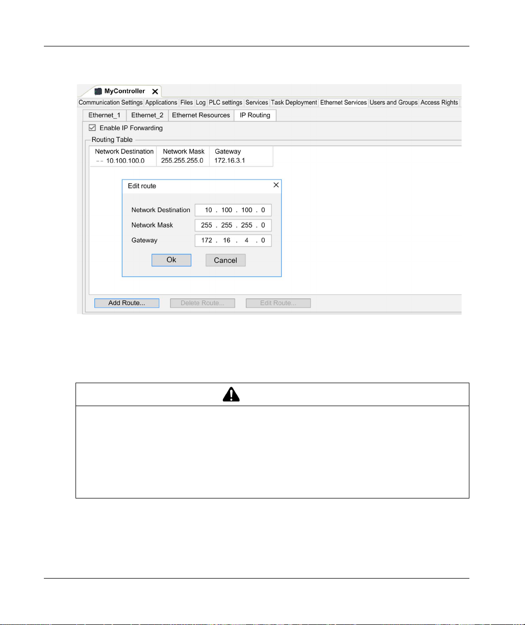
Controller Device Editor
To add a route, double click My controller then click Ethernet Services → IP Routing → Add
Route.
For reasons of Internet security, TCP/IP forwarding is disabled by default. Therefore, you must
manually enable TCP/IP forwarding. However, doing so may expose your network to possible
cyberattacks if you do not take additional measures to protect your enterprise. In addition, you may
be subject to laws and regulations concerning cybersecurity.
84
WARNING
UNAUTHENTICATED ACCESS AND SUBSEQUENT NETWORK INTRUSION
Observe and respect any an all pertinent national, regional and local cybersecurity and/or
personal data laws and regulations when enabling TCP/IP forwarding on an industrial network.
Isolate your industrial network from other networks inside your company.
Protect any network against unintended access by using firewalls, VPN, or other, proven
security measures.
Failure to follow these instructions can result in death, serious injury, or equipment damage.
EIO0000003651 05/2020
Page 85

Users Rights
Introduction
Users and Groups and Access Right tabs
access rights groups and the associated access rights, to control the access on projects. For more
informations, refer to the EcoStruxure Machine Expert Programming Guide
Machine Expert, Programming Guide)
Login and passwords
Login and password are set by default. They must be activated and can be reset as origin.
This table describes how to log in:
(see page 74)
.
Controller Device Editor
allows to manage user accounts, user
(see EcoStruxure
Server/feature First connection
Login / Password
EcoStruxure Machine
Expert
HTTP No login possible Administrator /
FTP No login possible Administrator /
OPC-UA No login possible Administrator /
Change Device Name
feature
Administrator /
Administrator
No login possible Administrator /
User rights
Login / Password
Administrator /
configured password
configured password
configured password
configured password
configured password
Connection after reset to default
Login / Password
Administrator / Administrator
No login possible
No login possible
No login possible
No login possible
WARNING
UNAUTHORIZED DATA AND/OR APPLICATION ACCESS
Secure access to the FTP/Web/OPC-UA server(s) using User Rights.
If you disable User Rights, disable the server(s) to prevent any unwanted or unauthorized
access to your application and/or data.
Failure to follow these instructions can result in death, serious injury, or equipment damage.
NOTE: Anonymous login can be restored by removing the user rights in the User Management
(see page 141)
page
NOTE: Only ASCII characters are supported by the controller for login and password.
of the web server.
EIO0000003651 05/2020 85
Page 86

Controller Device Editor
Default users and groups
One user and two groups are set by default:
User: Administrator
Groups: Administrator and Everyone
Access Rights
You can give Access Rights to groups.
You can allow the following operations through the access rights:
VIEW
MODIFY
EXECUTE
ADD_REMOVE
Troubleshooting
The only way to gain access to a controller that has user access-rights enabled and for which you
do not have the password(s) is by performing an Update Firmware operation. This clearing of User
Rights can only be accomplished by using a SD card to update the controller firmware. In addition,
you may clear the User Rights in the controller by running a script (refer to Reset the User Rights
to Default
(see page 278)
memory, but restores the ability to access the Controller.
). This effectively removes the existing application from the controller
86
EIO0000003651 05/2020
Page 87

Modicon M262 Logic/Moti on Controller
Embedded I/Os Configuration
EIO0000003651 05/2020
Embedded Inputs and Ou tputs Configuratio n
Chapter 10
Embedded Inputs and Outputs Configuration
What Is in This Chapter?
This chapter contains the following sections:
Section Topic Page
10.1 Configuring the Fast I/Os 88
10.2 Hardware Encoder Interface 94
EIO0000003651 05/2020 87
Page 88

Embedded I/Os Configuration
Configuring the Fast I/Os
Section 10.1
Configuring the Fast I/Os
Embedded I/Os Configuration
Overview
The embedded I/O function allows configuration of the controller inputs and outputs.
The TM262• logic controllers provide:
4 fast inputs.
4 fast outputs.
Accessing the I/O Configuration Window
Follow these steps to access the I/O configuration window:
Step Description
1 Double-click DI (digital inputs) or DQ (digital outputs) in the Devices tree. Refer to Devices tree
(see page 21)
2 Select the I/O Configuration tab.
.
88
EIO0000003651 05/2020
Page 89

Configuration of Digital Inputs
This figure shows the I/O Configuration tab for digital inputs:
NOTE: For more information on the I/O Mapping tab, refer to the EcoStruxure Machine Expert
Programming Guide
Embedded I/Os Configuration
(see EcoStruxure Machine Expert, Programming Guide)
.
EIO0000003651 05/2020 89
Page 90

Embedded I/Os Configuration
Digital Input Configuration Parameters
For each digital input, you can configure the following parameters:
Parameter Value Description Constraint
Filter 0.000 ms
Latch No*
Event No*
Run/Stop
Input
* Parameter default value
0.001 ms
0.002 ms
0.005 ms
0.01 ms
0.05 ms
0.1 ms
0.5 ms
1ms
4ms*
12 ms
Yes
Rising edge
Falling edge
Both edges
None*
I0...I3
Reduces the effect of
noise on a controller
input.
Allows incoming pulses
with amplitude widths
shorter than the
controller scan time to be
captured and recorded.
Event detection Available if Latch disabled. When Both edges is
The Run/Stop input can
be used to run or stop the
controller application.
Configure Filter to 0.000 if you don’t want to filter
the signal.
Available if Event disabled.
selected, and the input state is TRUE before the
controller is powered on, the first falling edge is
ignored.
Select one of the inputs to use as the Run/Stop
Input.
90
NOTE: The selection is grey and inactive if the parameter is unavailable.
EIO0000003651 05/2020
Page 91

Run/Stop Input
This table presents the different states:
Input states Result
State 0 Stops the controller and ignores external Run commands. FSP LED is red ON.
A rising edge From the STOPPED state, initiate a start-up of an application in RUNNING state, if
State 1 The application can be controlled by:
NOTE: Run/Stop input is managed even if the option Update I/O while in stop is not selected in
Controller Device Editor (PLC settings tab)
Inputs assigned to configured expert functions cannot be configured as Run/Stop inputs.
For further details about controller states and states transitions, refer to Controller State Diagram
(see page 52)
UNINTENDED MACHINE OR PROCESS START-UP
Verify the state of security of your machine or process environment before applying power to
the Run/Stop input.
Use the Run/Stop input to help prevent the unintentional start-up from a remote location.
Failure to follow these instructions can result in death, serious injury, or equipment damage.
Embedded I/Os Configuration
no conflict with Run/Stop switch position.
EcoStruxure Machine Expert (Run/Stop)
A hardware Run/Stop switch
Application (Controller command)
Network command (Run/Stop command)
Run/Stop command is available through the Web Server command.
(see page 77)
.
.
WARNING
EIO0000003651 05/2020 91
Page 92

Embedded I/Os Configuration
Capture Input
Capture Inputs tab allows you to select captures, exclusively for motion applications, and manage
them in the I/O Configuration tab.
For each capture, you can configure the following parameters:
Parameter Type Value Description Constraint
Capture edge UINT Enum Falling edge
RealTimeAccess BOOL TRUE Using real time
For more information on motion applications and function blocks related, as MC_TouchProbe and
MC_AbortTrigger, refer to M262 Synchronized Motion Control Library Guide.
Rising edge
Both edges
Configure the edge on
which the encoder
position is captured.
access.
Enable the capture
positions in Capture
Inputs tab.
Do not use with the
function blocks from
the M262 Encoder
Library.
Enable the capture
positions in Capture
Inputs tab.
Do not use with the
function blocks from
the M262 Encoder
Library.
Configuration of Digital Outputs
This figure shows the I/O Configuration tab for digital outputs:
NOTE: For more information on the I/O Mapping tab, refer to the EcoStruxure Machine Expert
Programming Guide.
92
EIO0000003651 05/2020
Page 93

Digital Output Configuration Parameters
This table presents the function of the different parameters:
Parameter Function
General Parameters
Alarm Output Select an output to be used as alarm output
Rearming Output Mode Select the rearming output mode
NOTE: The selection is grey and inactive if the parameter is unavailable.
Alarm Output
This output is set to logical 1 when the controller is in the RUNNING state and the application
program is not stopped at a breakpoint.
The alarm output is set to 0 when a task is stopped at a breakpoint to signal that the controller has
stopped executing the application and when the controller is stopped.
NOTE: Outputs assigned to configured expert functions cannot be configured as the alarm output.
Rearming Output Mode
Fast outputs of the Modicon M262 Logic/Motion Controller use push/pull technology. In case of
detected error (short-circuit or over temperature), the output is put in tri-state and the condition is
signaled by status bit and PLC_R_IO_STATUS.This is also signaled by %IX1.0.
Two behaviors are possible:
Automatic rearming: as soon as the detected error is corrected, the output is set again according
to the current value assigned to it and the diagnostic value is reset.
Manual rearming: when an error is detected, the status is memorized and the output is forced
to tri-state until user manually clears the status (see I/O mapping channel).
In the case of a short-circuit or current overload, the common group of outputs automatically enters
into thermal protection mode (all outputs in the group are set to 0), and are then periodically
rearmed (each second) to test the connection state. However, you must be aware of the effect of
this rearming on the machine or process being controlled.
(see page 93)
(see page 93)
Embedded I/Os Configuration
.
.
WARNING
UNINTENDED MACHINE START-UP
Inhibit the automatic rearming of outputs if this feature is an undesirable behavior for your
machine or process.
Failure to follow these instructions can result in death, serious injury, or equipment damage.
NOTE: Automatic rearming of outputs can be inhibited through the configuration.
EIO0000003651 05/2020 93
Page 94

Embedded I/Os Configuration
Hardware Encoder Interface
Section 10.2
Hardware Encoder Interface
What Is in This Section?
This section contains the following topics:
Hardware Encoder Interface 95
Adding an Encoder 97
Encoder Motion Functions 100
Topic Page
94
EIO0000003651 05/2020
Page 95

Hardware Encoder Interface
Introduction
The controller has a specific hardware encoder interface that can support:
Incremental encoder
SSI absolute encoder
Incremental Mode Principle Description
The incremental mode behaves like a standard up/down counter, using pulses and counting these
pulses.
Positions must be preset and counting must be initialized to implement and manage the
incremental mode.
The counter value can be stored in the capture register by configuring an external event.
Incremental Mode Principle Diagram
The following diagram provides an overview of the encoder in incremental mode:
Embedded I/Os Configuration
SSI Mode Principle Description
The SSI (Synchronous Serial Interface) mode allows the connection of an absolute encoder.
The position of the absolute encoder is read by an SSI link.
EIO0000003651 05/2020 95
Page 96

Embedded I/Os Configuration
SSI Mode Principle Diagram
The following diagram provides an overview of the encoder in SSI mode:
I/O mapping
This variable is used by the library to identify the encoder, incremental or SSI, to which the function
block applies.
96
EIO0000003651 05/2020
Page 97

Adding an Encoder
Introduction
In order to use the encoder interface, the Modicon M262 Logic/Motion Controller has a specific
hardware encoder interface that can support:
Incremental encoder
SSI encoder
For more information on usable function blocks, refer to Modicon M262 Logic/Motion Controller Encoder Library Guide
Adding an Encoder
To add an encoder to your controller, select the encoder in the Hardware Catalog. Drag and drop
it to the Devices tree on one of the highlighted nodes.
For more information on adding a device to your project, refer to:
• Using the Drag-and-drop Method
• Using the Contextual Menu or Plus Button
Guide)
Incremental Encoder Configuration
To configure the incremental encoder, double-click the encoder node in the Devices tree.
This table describes the incremental encoder configuration parameters:
(see Modicon M262 Logic/Motion Controller, Encoder Library Guide)
Embedded I/Os Configuration
.
(see EcoStruxure Machine Expert, Programming Guide)
(see EcoStruxure Machine Expert, Programming
Parameter Type Value Default Value Unit Description
Power supply
Voltage
selection
Power supply
monitor
General
Input Mode BYTE
EIO0000003651 05/2020 97
BYTE
Enum
BYTE
Enum
Enum
None
5V
24 V
Enabled
Disabled
Normal Quadrature x 1
Normal Quadrature x 2
Normal Quadrature x 4
Reverse Quadrature x 1
Reverse Quadrature x 2
Reverse Quadrature x 4
None ––
Disabled – Enable the power
supply monitor
Normal Quadrature x 1 – Select the period
measurement
interval
Page 98

Embedded I/Os Configuration
Parameter Type Value Default Value Unit Description
Counting Inputs
A Input
Filter BYTE
Enum
0.000
0.001
0.002
0.002 ms Set the filtering value
to reduce the bounce
effect on the input
0.005
0.05
0.01
0.08
0.5
1
4
12
B Input
Filter BYTE
Enum
0 0.002 ms Set the filtering value
to reduce the bounce
effect on the input
Preset Input
Z Input
Filter BYTE
Enum
0.000
0.001
0.002
0.002 ms Set the filtering value
to reduce the bounce
effect on the input
0.005
0.05
0.01
0.08
0.5
1
4
12
98
EIO0000003651 05/2020
Page 99

Embedded I/Os Configuration
SSI Encoder Configuration
To configure the SSI Encoder, double-click the encoder node in the Devices tree.
This table describes the SSI encoder configuration parameters:
Parameter Type Value Default Value Unit Description
Power supply
Voltage selection BYTE Enum None
Power supply monitor BYTE Enum Disabled Disabled – Enable the power supply monitor
Synchronous Serial Interface (SSI)
Transmission Speed BYTE Enum 100
Number of bits per
frame
Number of data bits USINT (8...32) 8 8 – Set the number of bits to count
Number of data bits /
turn
Number of status bits USINT (0...4) 0 0 – Set the number of bits to be
Parity BYTE Enum None None – Select the parity
Resolution reduction USINT (0...17) 0 0 – Set the resolution code
Binary coding BYTE Enum Binary Binary – Select the binary coding mode
USINT (8...64) 8 8 – Set the number of bits per frame
USINT (8...16) 8 8 – Set the number of data bits to
5V
24 V
250
500
None ––
250 KHz Select the speed of data
transmission
(header + data bits + status +
parity)
turn + bits to count points per turn
count points per turn
reserved for the status
Motion Functions
You can configure specific elements, exclusively for motion applications. For more information,
refer to Motion Functions tab
EIO0000003651 05/2020 99
(see page 100)
.
Page 100

Embedded I/Os Configuration
Encoder Motion Functions
Introduction
The encoder Motion Functions tab allows you to configure specific elements, exclusively for mo t ion
applications.
NOTE: These Motion Functions must not be used with the M262Encoder library when check boxes
for Axis, Scaling, Filter and/or DeadTimeCompensation are enabled.
Configuring the Motion Functions
This table describes the procedure to configure the motion functions
Step Action
1 Double-click the encoder node in the Devices tree.
2 open the Motion Functions tab.
3 Enable check boxes for Axis, Scaling, Filter and/or DeadTimeCompensation.
Incremental/SSI Encoder
Result: The configuration parameters are displayed in the Incremental Encoder configuration tab or in
the SSI Encoder configuration tab.
This table describes the motion functions configuration parameters of the incremental encoder or
of the SSI encoder:
Parameter Type Value Default
Value
Scaling
IncrementResolution DINT 1...2,147,483,647 131072 IncrementResolution
PositionResolution LREAL 1.0...1.7976931348623158e+308 360.0 PositionResolution
GearIn UDINT 1...4,294,967,295 1 GearIn
GearOut UDINT 1...4,294,967,295 1 GearOut
InvertDirection BOOL FALSE FALSE Invert movement direction of the axis
Filter
AverageDuration UDINT 0...1024 0 Filter duration in Sercos cycles
DeadTimeCompensation
Delay LREAL -100.0...100.0 0 Delay of feedback movement values
Description
(position/velocity/acceleration) in
milliseconds. This delay will be
compensated by the system.
NOTE: The DeadTimeCompensation delay, without a filter, results in a very high signal deviation
of the feedback velocity and can result in unexpected behavior of a coupled slave axis.
100
EIO0000003651 05/2020
 Loading...