

TAC I/A Series
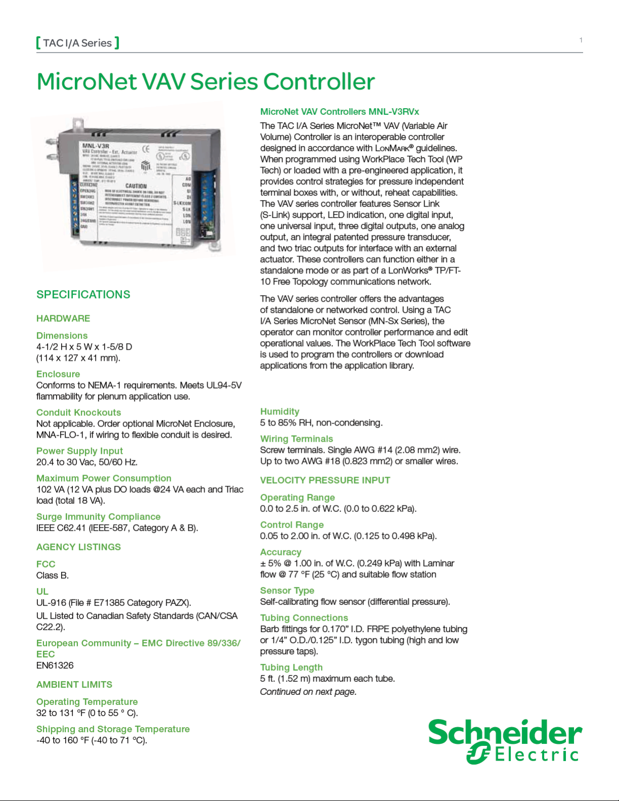
MNL-V3RVx Controllers
2
Continued from first page.
DIGITAL OUTPUTS
Relay Outputs
SW24H1, SW24H2, and SW24H3 Current
Ratings
24 VA each at 24 Vac, 50/60 Hz. Form A, SinglePole, Single-Throw (SPST), Normally-open. 300K
cycles at 24 Vac, 24 VA (0.4 power factor).
Triac Outputs
Current Ratings
18 VA (0.75 A) each output at 24 Vac. Total of 18 VA
for both outputs.
Typical Load
24 Vac synchronous motor with impedance protected
windings.
DIGITAL INPUT
Dry Contact. Detection of closed switch requires less
than 300 ohm. Detection of open switch requires
more than 100K ohm.
UNIVERSAL INPUT
1K ohm Balco Input
-40 to 250 °F (-40 to 121 °C) range. TSMN-81011,
TS-8000 Series or equivalent.
1K ohm Platinum Input
-40 to 240 °F (-40 to 116 °C) range.
TSMN-58011, TS-5800 Series or equivalent.
1K ohm Resistance
0 to 1.5K ohms.
10K ohm Thermistor with 11K ohm Shunt
Resistor
-40 to 250 °F (-40 to 121 °C) range. TSMN-57011850, TS-5700-850 Series or equivalent.
10K ohm Resistance
0 to 10.5K ohm.
Voltage
0 to 5 Vdc.
Current
0 to 20 mA requires an external 250 ohm shunt
resistor.
Digital Input (Mode Setting for UI)
Dry Contact. Detection of closed switch requires less
than 300 ohm. Detection of open switch requires
more than 1.5K ohm.
ANALOG OUTPUT
Current
0 to 20 mA (output load range from 80 to 550 ohm).
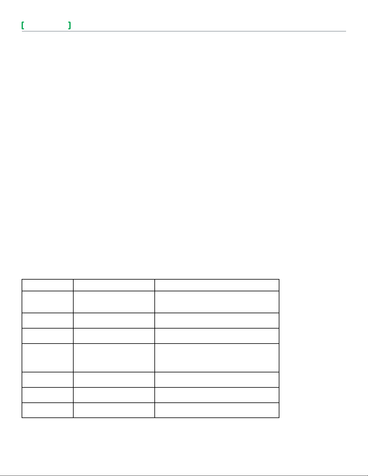
INPUTS FROM MN-Sx TAC I/A SERIES MICRONET SENSOR
Inputs Description MN-Sx Sensor
Space Temperature 32 to 122 °F (0 to 50 °C) MN-S1, MN-S1HT, MN-S2, MN-S2HT, MN-S3,
MN-S3HT, MN-S4, MN-S4HT, MN-S4-FCS, MNS4HT-FCS, MN-S5 and MN-S5HT
Space Humidity 5 to 95% RH, Non-condensing MN-S1HT, MN-S2HT, MN-S3HT, MN-S4HT,
MN-S4HT-FCS, and MN-S5HT
Adjustable Setpoint 40 to 95 °F (4 to 35°C) MN-S3, MN-S3HT, MN-S4, MN-S4HT, MN-S4-
FCS, MN-S4HT-FCS, MN-S5, and MN-S5HT
Override
Pushbutton
For standalone occupancy
control or remote status
monitoring of local status
condition.
Fan Operation and
Speed
Fan mode selection: On, Speed
(Low/Medium/High), or Auto.
System Mode System mode selection: Heat,
Cool, Off, or Auto.
Emergency Heat Emergency heat mode selection:
Enable or Disable
MN-S2, MN-S2HT, MN-S3, MN-S3HT, MN-S4,
MN-S4HT, MN-S5, and MN-S5HT
MN-S4, MN-S4HT, MN-S4-FCS, MN-S4HT-FCS,
MN-S5, and MN-S5HT
MN-S4, MN-S4HT, MN-S5, and MN-S5HT
MN-S5 and MN-S5HT
Schn eide r Elec tric
F-26366- 9 August 2013 tl
© 2013 Schneider Electr ic. All rights reserved.

TAC I/A Series
MNL-V3RVx Controllers
MODELS
Part Number Inputs/Outputs
Box Configuration Reheat Type Other
3 Digital Outputs (DO)
Cooling
Series Fan
Induction
Parallel Fan
MNL-V3RVx
1 Analog Output (AO)
a
2 Triac Outputs (TO)
1 Universal Input (UI)
1 Digital Input (DI)
a V denotes LonMark VAV (Variable Air Volume) profile. “x” denotes profile version.
b Available control strategies depend on controller I/O.
Control Strategies
Staged Electric
Reheat
Floating/Proportional
Hydronic Reheat
Time Proportioned
Occupancy
Satellite
b
3
FEATURES
Designed for new or existing systems, the VAV series
controller may be applied to pressure independent
terminal boxes with, or without, reheat capabilities.
The VAV controller offers the following types of Box
Configuration and Reheat control strategies:
• Cooling.
• Series Fan.
• Parallel Fan.
• Induction.
• Staged Electric Reheat.
• Floating/Proportional Hydronic Reheat.
• Time Proportioned.
• Capability to function in standalone mode or
as part of a LonWorks TP/FT-10 Free Topology
communications network.
• Proportional (P), Proportional Plus Integral (PI),
and Proportional Plus Integral and Derivative (PID)
control for cooling and heating.
• Patented pressure transducer for years of reliable,
accurate air flow readings.
• Air balancing using the TAC I/A Series
MicroNet VAV Flow Balance software.
• Directly compatible with terminal boxes which
contain a synchronous-motor-driven damper
actuator.
• Conforms to the LonMark VAV controller profile.
• Plenum-rated enclosure allows direct mounting in
plenum.
TAC I/A Series VAV FLow Balance Software
Provides flow balancing for networked and
standalone VAV series controllers. Features include:
• Local network control.
• Damper and fan adjustment.
• Setpoint monitoring and adjustment.
• Flow validation and calibration.
• Sequence, calibration, and control setpoint logs.
COMMUNICATIONS
Lon Works Networks
L
onWorks communications network uses an
FTT-10 Free Topology configuration. Controllers on
a L
onWorks network can communicate with each
other in a peer-to-peer fashion. A L
has a communications speed of 78k baud, using
unshielded, twisted-pair cabling, with connections
that are not polarity sensitive.
S-Link
The Sensor Link (S-Link) communications wiring
provides power and a communication interface for an
MN-Sx TAC I/A Series MicroNet sensor. The various
MN-Sx sensors can provide room temperature,
room humidity, setpoint adjustment, and occupancy
override. This connection uses two-wire, unshielded
cable and is not polarity sensitive. Maximum wire
length allowed between a controller and a TAC I/A
Series MicroNet Sensor is 200 ft (61 m).
onWorks network
Software Capabilities
• Conforms to the LonMark guidelines.
• WorkPlace Tech Tool is capable of reconfiguring
and editing application configuration data to
fit a wide range of variable air volume control
requirements.
• HVAC interoperability achieved through use of
LonMark HVAC profiles.
• Air balancing provided by the I/A Series MicroNet
VAV Flow Balance software.
Schn eide r Elec tric
F-26366- 9 August 2013 tl
© 2013 Schneider Electr ic. All rights reserved.

 Loading...