

Page 1
MNB-70
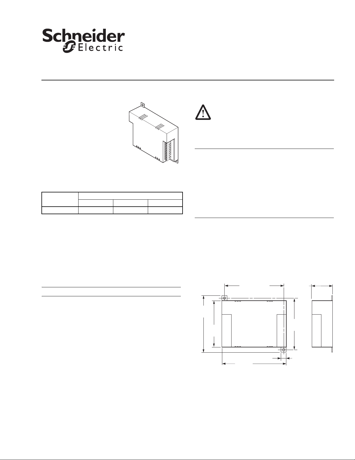
Dimensions shown
are in inches (mm).
5 (127)
4-19/32 (118)
4-13/32
(112)
3-5/8
(92)
4
(102)
1-19/32
(41)
3/8 (10)
Figure-1 MNB-70 Mounting Dimensions.
TAC I/A Series MicroNet BACnet
Zone Controller
Installation Instructions
Application
The TAC I/A Series™ MicroNet™
BACnet™ Zone Controller is an
interoperable controller with native
BACnet MS/TP communications
support. This controller
incorporates: three universal inputs;
three digital (Triac) outputs; one
universal output; Sensor Link
(S-Link) support; LED status
SW24H1
SW24H2
SW24H3
24H
24G(COM)
GND
STATUS
MSTP RCV
MSTP XMT
S-LK/COM
MSTP +
MSTP -
UO 1
AO
COM
UI 1
COM
UI 2
UI 3
SHLD
indication; and an “I-Am” button.
Model Chart
Model
Number
MNB-70 313
Inputs and Outputs
UI UO DO (Triacs)
Installation
Inspection
Inspect carton for damage. If damaged, notify carrier
immediately. Inspect controllers for damage upon receipt.
Requirements
• Installer must be a qualified technician
Precautions
When installing the MNB-70 controller, be sure to
follow the guidelines outlined in "Precautions" on
page 3.
Location
The MNB-70 controllers are suitable for indoor use only.
Caution:
• Avoid locations where excessive moisture, corrosive
fumes, vibration, or explosive vapors are present.
• Avoid electrical noise interference. Do not install near
large contactors, electrical machinery, or welding
equipment.
• Locate where ambient temperatures do not exceed 131°F
(55°C) or fall below 32°F (0°C), and relative humidity
does not exceed 85% or fall below 5%, non-condensing.
MNB-70 controllers can be mounted in any direction and on
any plane.
Dimensions
Mounting dimensions are shown in Figure-1.
Note: The following items are not provided.
• Job wiring diagrams
• Tools:
– Screw drivers
– Digital volt-ohm meter (DVM)
– Drill and bits for mounting screw
– Static protection wrist strap
• MNA-FLO-1 enclosure for connecting to conduit (optional)
• MS/TP trunk end-of-line termination resistor kit,
120 Ω ±5%, part number 40-1758.
• Class 2 power transformer supplying a nominal 24 Vac,
sized appropriately for the controller (15 VA) plus the
anticipated Digital Output (DO) loads. In European
Community, transformer must conform to EN 60742
• Two #10 sheet metal screws
08-13 © 2013 Schneider Electric. All rights reserved. F-27456-3
Page 2
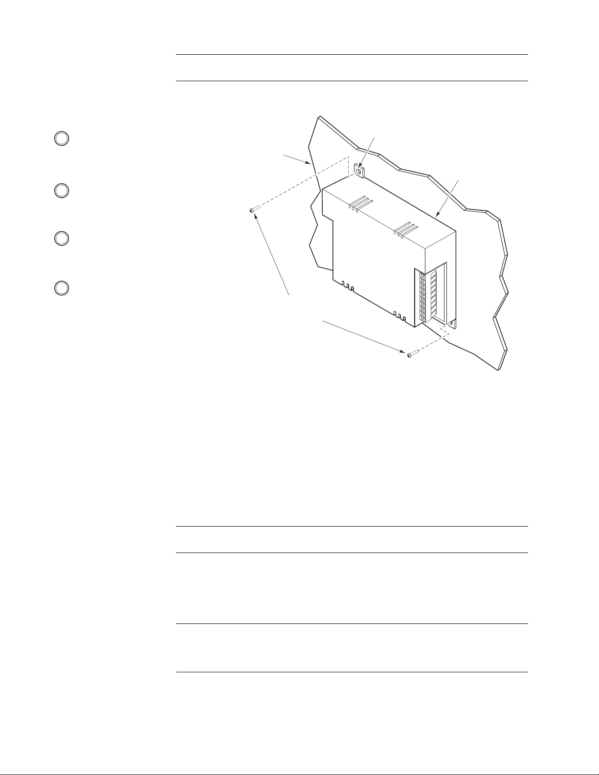
Mounting Mount the controller according to the instructions in Figure-2.
AO
SW24H1
SW24H2
SW24H3
24H
24
G(C
OM)
GND
S
T
A
TUS
MS
TP RCV
MS
T
P X
MT
UO 1
CO
M
UI 1
C
O
M
UI 2
UI
3
S
-LK/
COM
M
STP +
SHLD
M
S
TP -
Controller
#10 Pan Head
Screws (2)
(not supplied)
Mounting Tab
(1 of 2)
1 Select a mounting location on the panel.
Note: The MNB-70 may be mounted in
any orientation.
2 Holding the controller in position,
mark the locations of the two
mounting holes on the panel.
3 Set the controller aside and then drill the
marked mounting holes, using a drill bit
sized to the #10 mounting screws.
4 Secure the controller to the panel,
using two #10 screws (not supplied).
Panel
Figure-2 MNB-70 Mounting.
Warning: Electrical shock hazard! Disconnect power before installing or removing the
cover.
Controller Addressing
DIP Switch
Each MicroNet BACnet controller is equipped with a DIP switch for setting the controller’s
MS/TP network address. Once the address is set, the network is properly wired, and all
routers are configured, WorkPlace Tech Tool (WP Tech) and other Schneider Electric tools
will be able to “see” and work with all the networked BACnet devices. For guidance in
assigning a DIP switch setting that will optimize system performance, refer to the WorkPlace
Tech Tool BACnet Engineering Guide Supplement, F-27356.
Note: Support for the MNB-70 is only found in WP Tech Version 5.6 and later (covered in
Revision 2 of F-27356).
Other BACnet Devices
The UNC and other BACnet devices on the network can work with the MicroNet BACnet
controller once they are assigned unique identifiers and names. MicroNet BACnet
controllers are configured in this way through the Commissioning Tool.
Note: The logical addressing of devices (i.e. the assignment of unique identifiers and
names) is not a prerequisite for using Schneider Electric network management tools. It is,
however, a prerequisite for using the UNC and third-party BACnet devices with MicroNet
BACnet controllers.
EOL Termination
If the controller is at the end-of-line on the MS/TP trunk, set termination according to the
MicroNet BACnet Wiring, Networking, and Best Practices Guide, F-27360, using an
end-of-line termination resistor kit, 120 Ω ±5%, part number 40-1758.
2 © 2013 Schneider Electric. All rights reserved. F-27456-3
Page 3

Installation Completion
Finish installing the MNB-70 controller by performing the wiring and network configuration
tasks outlined in the MicroNet BACnet Wiring, Networking, and Best Practices Guide,
F-27360. Information covered in this Guide include:
• Communications wiring • Logical addressing of devices
– MicroNet BACnet wiring
– Sensor Link (S-Link) wiring
• Input/Output wiring • Troubleshooting
• Power supply wiring • A list of related documentation
• Mechanical hardware checkout
Precautions General
Warning: Electrical shock hazard! Disconnect power before installing or removing the
cover.
• Follow Static Precautions (below) when installing this equipment.
• Use copper conductors that are suitable for 167°F (75°C).
• Make all connections according to electrical wiring diagram, national and local electrical
codes.
Static Precautions
• Static charges damage electronic components. The microprocessor and associated
circuitry are extremely sensitive to static discharge. Use the following precautions when
installing, servicing, or operating the system.
• Work in a static-free area.
• Discharge static electricity by touching a known, securely grounded object.
• Use a wrist strap connected to earth ground when handling the controller’s printed
circuit board.
• Configuration of routers
• Communications hardware checkout
Federal Communications Commission (FCC)
This equipment has been tested and found to comply with the limits for a Class A digital
device, pursuant to Part 15 of the FCC Rules. These limits are designed to provide
reasonable protection against harmful interference when the equipment is operated in a
commercial environment. This equipment generates, uses, and can radiate radio frequency
energy, and, if not installed and used in accordance with the instruction manual, may cause
harmful interference to radio communications. Operation of this equipment in a resdential
area is likely to cause harmful interference, in which case the user will be required to correct
the interference at his own expense.
Canadian Department of Communications (DOC)
This Class A digital apparatus meets all requirements of the Canadian Interference-Causing
Equipment Regulations.
European Community Directives
This equipment meets all requirements of European Community Directives for
Electromagnetic Compatibility (89/336/EEC).
F-27456-3 © 2013 Schneider Electric. All rights reserved. 3
Page 4

Distributed, manufactured, and sold by Schneider Electric. I/A Series trademarks are owned by Invensys Systems, Inc. and are used on this product under master
license from Invensys. Invensys does not manufacture this product or provide any product warranty or support. For service, support, and warranty information, contact
Schneider Electric at 1-888-444-1311.
All brand names, trademarks and registered trademarks are the property of their respective owners. Information contained within this document is subject to change without notice.
Schneider Electric
F-27456-3 August 2013 ptm
© 2013 Schneider Electric. All rights reserved.
 Loading...