

Page 1
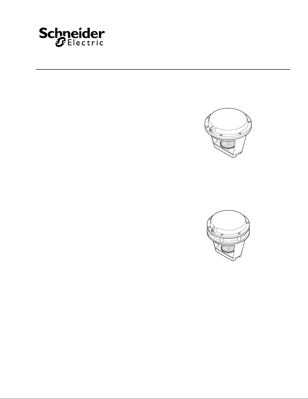
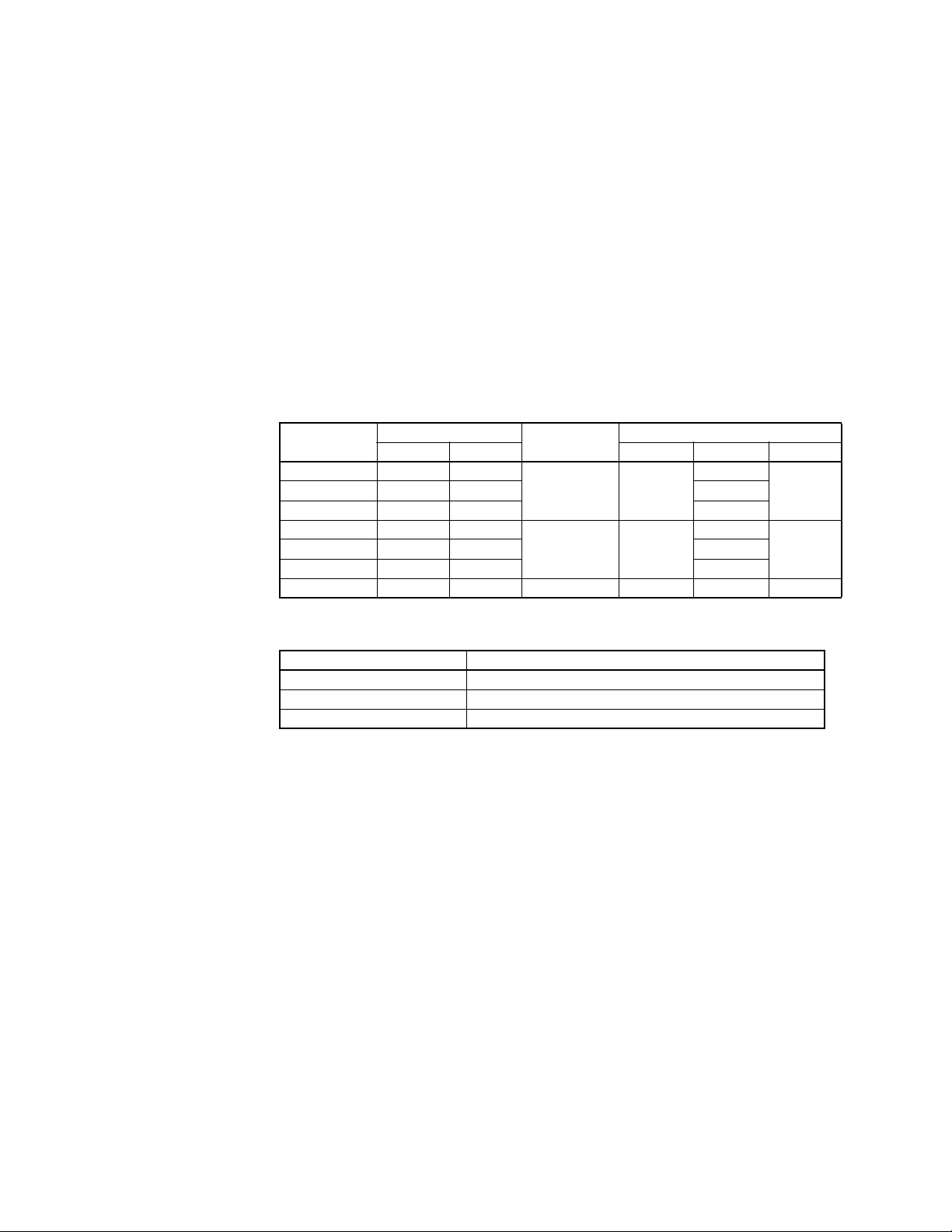
Application
Typical of MK-6600 Series
and MK-6800 Series
MK-6911
These valve actuators, with a 50 sq. in. (323 cm2)
effective diaphragm area, are used for propo rt ion al
pneumatic control of hot water or chilled water valves.
• MK-66x1 is used to control 1-1/2 in. to 2 in. VB-7xxx
series valves.
• MK-68x1 is used to control 2-1/2 in. to 4 in.
VB-9xxx series valves
• MK-681 1 is used to control 2- 1/2 in. to 5 in .VB-8xx3
series valves and 2-1/2 in. to 4 in.
VB-9xxx series valves
MK-6600 Series,
MK-6800 Series, and MK-6911
Pneumatic Valve Actuators
General Instructions
• MK-6911 is used to control 6 in. VB-8xxx valves
Features
• Rugged die cast aluminum housing.
• Replaceable beaded molded neoprene diaphragm.
• Built-in spring to retract output shaft.
• Adjustable start point on loss of air pressure.
Applicable Literature
• Pneumatic Products Catalog, F-27383
• Cross-Reference Guide, F-26789
• Reference Manual, F-21683
• Application Manual, F-21335
• AV-430 Linkage General Instructions, F-19072
• AV-495 Linkage General Instructions, F-21665
• AV-497 Linkage General Instructions, F-27253
Printed in U.S.A. 1/10 © Copyright 2010 Schneider Electric All Rights Reserved. F-13895-13
Page 2
SPECIFICATIONS
Construction:
Housing, Die cast aluminum.
Diaphragm, Replaceable beaded molded neoprene.
Stroke: (Table-1).
Effective Area: 50 sq. in. (323 cm2).
Spring: Retracts actuator shaft and raises valve stem on loss of air pressure.
Nominal Spring Range: (Table-1).
Start Point: Adjustable ±2 psi (14 kPa).
Maximum Air Pressure: 30 psig (207 kPa).
Ambient Temperature Limits:
Shipping, -40 to 220 °F (-40 to 104 °C).
Operating, -20 to 220 °F (-29 to 104 °C).
Air Connections: 1/8 in. FNPT.
Valve Linkage: Order separately (Table-2).
Locations: NEMA Type 1 only.
Mounting: In any upright position with actuator head above center line of valve body.
Dimensions: 7-3/4 H x 10-1/2 W x 10-1/2 D in. (199 x 267 x 267 mm).
Table-1 Model Chart.
Model Number
MK-6601 3 to 8 21 to 55
MK-6621 8 to 13 55 to 90 —
MK-6801 3 to 8 21 to 55
MK-6811 5 to 10 34 to 69 2-1/2" to 5"
MK-6821 8 to 13 55 to 90 —
MK-6911 5 to 10 34 to 69 1-3/4 (44) — 6" —
*Nominal no load spring range based on normal stroke
Nominal Spring Range*
psig kPa VB-7xxx VB-8xxx VB-9xxx
Nominal Stroke
in. (mm.)
1-1/2" to 2"
1/2 (13)
1 (25) —
Valve Compatibility
(40 to 50
mm)
—
—
2-1/2" to 4"
(65 to 80
mm)
Table-2 Valve Linkage.
Valve Linkage Valve Body Series
AV-430 VB-7xxx 1-1/2 in. to 2 in. (40 to 50 mm)
AV-495 VB-9xxx 2-1/2 in. to 4 in. (65 to 80 mm)
AV-497 VB-8xxx 2-1/2 in. to 6 in.
—MK-6611 5 to 10 34 to 69 —
ACCESSORIES
AK-42309-500 Positive positioner and linkage
TOOL-75 Spring compression tool
TOOL-95 Pneumatic calibration tool kit
MK-6600 Series
PNV-245-013 3 to 8 psig green spring
PNV-245-015 5 to 10 psig black spring
PNV-245-018 8 to 13 psig blue spring
MK-6700 and MK-6800 Series
PNV-245-103 3 to 8 psig green spring
PNV-245-105 5 to 10 psig black spring
PNV-245-108 8 to 13 psig blue spring
MK-6900 Series
PNV-245-145 5 to 10 psig black spring
PNV-245-148 8 to 13 psig blue spring
All Series
PNV-202 Diaphragm
2 © Copyright 2010 Schneider Electric All Rights Reserved. F-13895-13
Page 3
INSTALLATION
C A U T I O N
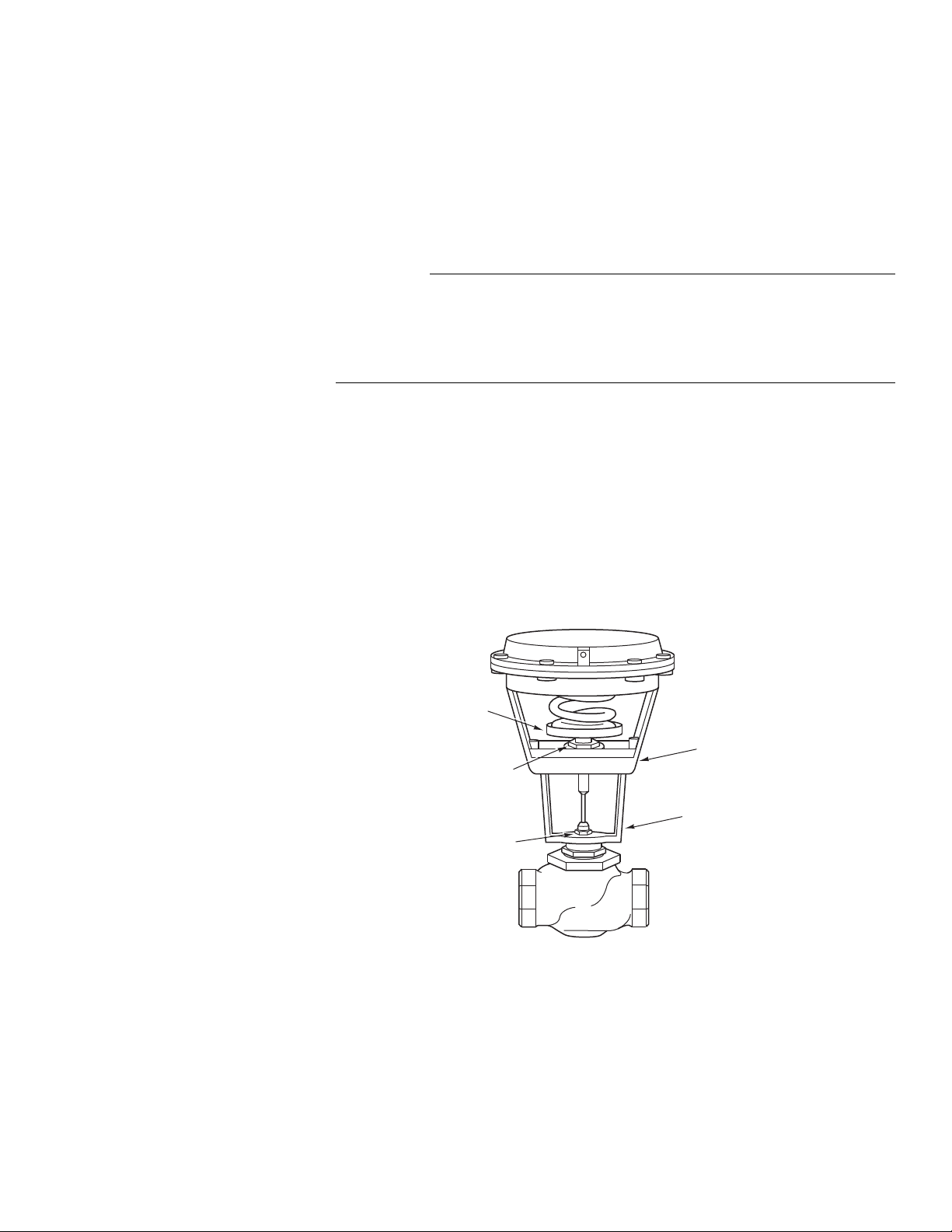
Spring
Retainer
Plate
Brass Hex Nut
for adjusting
start point
Bracket Nut
Actuator to Yoke
Mounting Bolts (2)
Mounting
Bracket
Inspection
Requirements
Mounting
Inspect the package for damage. If damaged, notify the appropriate carrier immediately.
If undamaged, open the package and inspect the device for obvious damage. Return
damaged products.
• Piping diagrams.
• Tools (not provided): Appropriate wrenches for mounting bolts and adjustments.
• Training: Installer must be a qualified, experienced technician or fitter.
• Make all connections in accordance with the piping diagram.
• Avoid locations where excessive moisture, corrosive fumes, or vibration are present.
• The actuator can be mounted in any position above the centerline of the valve body.
When selecting a location, allow sufficient room for accessories and for service of the
product.
The actuator may be shipped assembled to a valve body or as a separate component.
These instructions are intended for use where the actuator is to be installed to a linkage and
valve body, as a replacement unit, or when the actuator must be removed during valve
installation.
Figure-1 Typical Pneumatic Valve Assembly with MK-6xxx Series Actuator.
F-13895-13 © Copyright 2010 Schneider Electric All Rights Reserved. 3
Page 4

Removing Actuator from Valve Body (Figure-1)
N O T E
W A R N I N G
It is not necessary to remove the mounting bracket from the valve body in order to service
the actuator. If removal of the yoke is required, follow step 3.
1. Remove the connecting pin between the actuator piston stem and the valve stem extension. A slight amount of air pressure to the actuator may b e necessary to loosen the pin.
2. Remove the two bolts holding the actuator to the yoke, and lift up the actuator.
3. If it is necessary to remove the mounting bracket: Current style valves (valves that do not require removal of packing nut to mount
the actuator):
a. Remove the bracket nut.
b. Lift the actuator and mounting bracket off the valve body. Obsolete style valves (valves that require removal of packing nut to mount the actuator):
Any 2-1/2 in. to 6 in. VB-9xxx valve body date coded before 8603 (1986, third week) must
have the valve packing nut removed and replaced along with the bracket nut. Before
removing the packing nut, isolate the valve body using shutoff valves or depressurize the
system to zero gauge and drain the piping. System pressure could cause packing parts
to blow out with potential of injury and/or water damage.
a. Remove the packing nut.
b. Remove the bracket nut.
c. Lift the actuator and mounting bracket off the valve body.
Installing Actuator on Valve Body (Figure-1)
If the mounting bracket has been removed, re-install it making certain that the bracket nut is
securely tightened. (On obsolete style valves, which require removal of the packing nut to
mount the actuator, make certain that the packing nut is tight — tightened four turns.)
1. Place the actuator on the mounting bracket and secure with two bolts. Be sure the air connection is in the proper location.
2. Secure the actuator piston stem to the valve stem extension with the connecting pin. It may be necessary to apply a slight amount of air pressure to the actuator to line up the pin holes.
For additional information, refer to AV-430 Linkage General Instructions, F-19072,
AV -495 Linkage General Instructions F-21665, or AV -497 Linkage General Instructions
F-27253.
4 © Copyright 2010 Schneider Electric All Rights Reserved. F-13895-13
Page 5

ADJUSTMENTS
Start Point
Adjustment Nut
Center Stud
Sleeve
Spring
Retainer
Plate
C
T
The start point adjustment is the only actuator adjustment (Figure-1). The start point is the
air pressure which, when applied to the actuator, causes the piston to begin to move
downward under a no load condition.
In the course of meeting system requirements or replacing the diaphragm spring, the start
point may have been changed. T o adjust the start point, proceed as follows (viewing actuator
in position shown in
Figure-1).
1. Apply desired air pressure to the actuator.
2. Rotate the start point adjustment nut until the desired start point is obtained.
To raise the start point, rotate the adjustment nut clockwise (CW).
To lower the start point, rotate the adjustment nut counterclockwise (CCW).
Figure-2 Using Spring Compression Tool.
enter Stud
hreads
Figure-3 TOOL-75 Spring Compression Tool.
F-13895-13 © Copyright 2010 Schneider Electric All Rights Reserved. 5
Page 6

Cover
Spring
Retainer Plate
Piston
Diaphgram
(PNV-202)
Spring
Actuator
Lower
Housing
Adjustment Nut
(See ACCESSORIES
for part numbers)
6 © Copyright 2010 Schneider Electric All Rights Reserved. F-13895-13
Figure-4 Exploded View of Actuator.
Page 7

MAINTENANCE
W A R N I N G
N O T E
W A R N I N G
N O T E
FIELD REPAIR
Regular maintenance of the total system is recommended to assure sustained performance.
Replacing Actuator Diaphragm (Figure-2, Figure-3, and Figure-4)
Strong spring forces are present. Removing the actuator top without securing the spring
can result in violent release of spring energy — perhaps resulting in flying parts. Follow
the procedure below to prevent possible injury and damage to equipment.
1. Remove the actuator from the yoke as explained in the “Installation” section.
2. Place the actuator upside down on the cover top.
3. Thread the center stud of TOOL-75 into the piston stem.
4. Turn the TOOL-75 sleeve down until it rests on the actuator housing.
5. Holding the center stud of TOOL-75 with a small rod or screwdriver to keep it from
turning, turn the sleeve clockwise (CW) to compress the actuator spring. When the
spring and piston rotate freely within the actuator, the spring is sufficiently compressed
to permit removing the actuator cover.
6. Remove the cover screws, cover, and diaphragm.
7. Install the replacement diaphragm and follow the above steps in reverse order.
Be sure that the diaphragm rib fits properly in the actuator cover groove to prevent air
from leaking from the diaphragm.
Replacing Actuator Spring (Figure-2, Figure-3, and Figure-4)
Strong spring forces are present. Removing the actuator top without securing the spring
can result in violent release of spring energy — perhaps resulting in flying parts. Follow
the procedure below to prevent possible injury and damage to equipment.
1. Follow the steps outlined for replacing the diaphragm.
2. Place the actuator upside down on the piston top.
3. Holding the center stud of TOOL-75 with a small rod or screwdriver to keep it from turning, turn the sleeve counterclockwise (CCW) to release the spring tension.
The spring can be replaced with an identical spring without changing the start point
adjustment. To do this, be sure that the brass start point adjustment nut does not rotate
within the spring retainer plate. T o make certain the spring range has not been changed,
refer to the “Adjustments” section.
4. Remove TOOL-75 center stud from the actuator piston stem.
5. Lift the actuator lower housing away from the spring and piston assembly.
6. Lift the adjustment nut and spring retainer plate off the spring.
7. Replace the spring and re-install the parts removed above in the proper order.
F-13895-13 © Copyright 2010 Schneider Electric All Rights Reserved. 7
Page 8

On October 1st, 2009, TAC became the Buildings business of its parent com pany Sc h neider Electr ic . This doc um ent ref lect s the visual identity of Schneider Electric,
ho wever there remains refer ences t o TAC as a cor p orate brand i n the body copy. As eac h document is updated, the body copy wil l be changed to reflec t appropriate
corpo rate bra nd ch a nges.
Copyright 2010, Schneider Electric
All brand names, trademarks and registered
trademarks are the property of their respective
owners. Information contained within this
document is subject to change without notice.
F-13895-13
 Loading...