

Page 1
Application
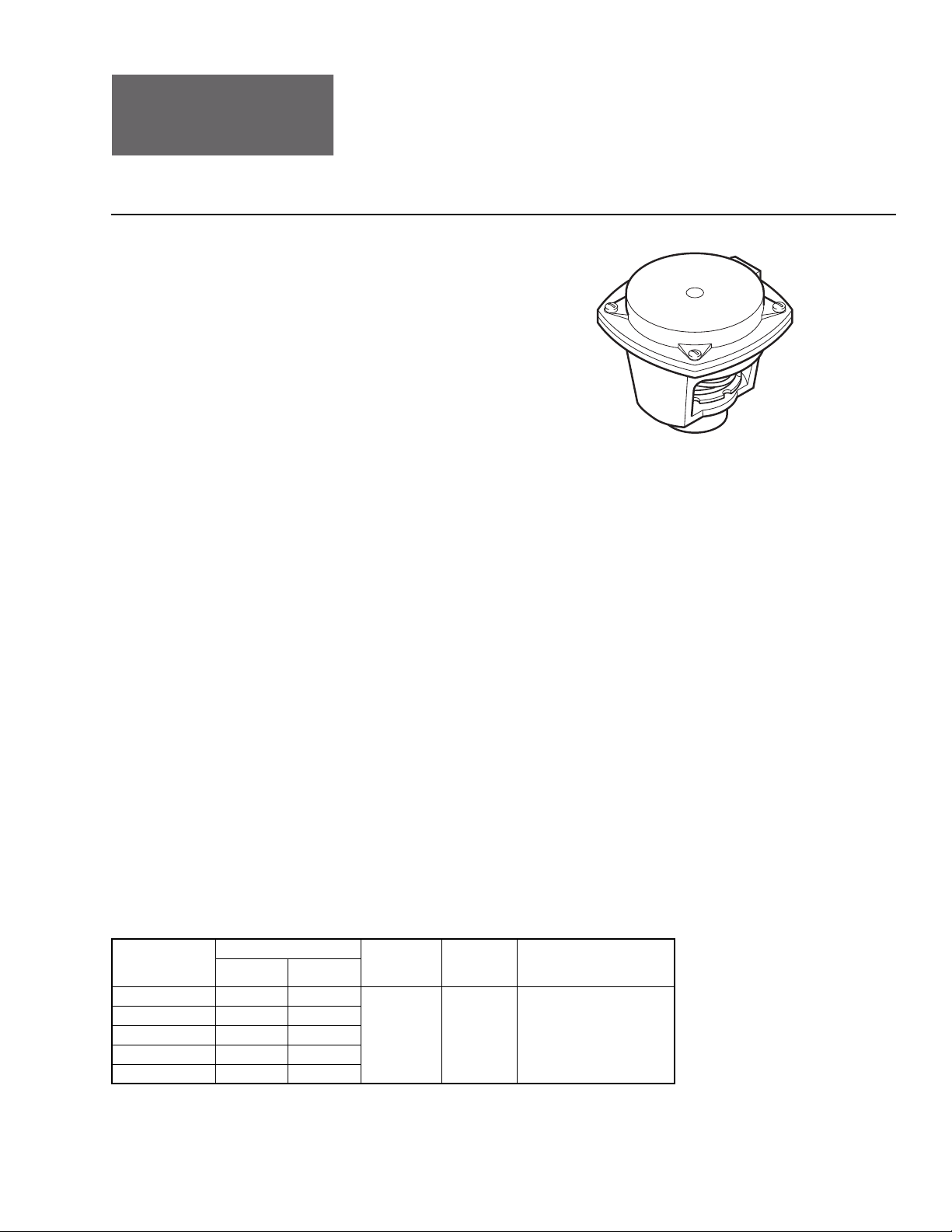
These valve actuators, with an 11 sq. in. (71 cm2) effective
diaphragm area, are used with VB-7xxx series valves for
proportional pneumatic control of hot water or chilled water
valves.
The MK-46xx Series may also be mounted on discontinued
1/2" through 1-1/4" TAC
VB-111, VB-131, VB-314, and VB-9xxx series valves.
MK-46xx Series
Pneumatic Valve Actuators
General Instructions
SPECIFICATIONS
Construction:
Housing, Die cast alum
Diaphragm, Replaceable beaded molded
neoprene.
Stroke: (Table-1).
Effective Area: 11 sq. in. (71 cm
Spring: Retracts actuator shaft and raises valve stem
on loss of air pressure.
Nominal Spring Range: (Table-1).
Start Point:
MK-4601, MK-4621:Adju
(+7/-14 kPa).
MK-4611, MK-4641: ±2 psig (±14 kPa)
MK-4621-422: 10 psi
Maximum Air Pressure: 30 psig (207 kPa).
Ambient Temperature Limits:
Shipping, -40 to 220 °F (-40 to
Operating, -20 to 220 °F (-29 to 104 °C).
Air Connections: 1/8 in. FNPT.
Valve Linkage: AV-401 (order separately).
Locations: NEMA Type 1 only.
Mounting: In any upright position with actuator head
ve horizontal center line of valve body.
abo
Dimensions: 3-7/8" H x 4-3/4" W x 4-3/4" D in. (99 x
121 x 121 mm).
inum.
2
).
stable +1/-2
g (69 kPa)
psi
104 °C).
MK-46xx Series
Features
• Rugged die cast aluminum housing
• Replaceable beaded molded neoprene diaphragm
• Built-in spring to retract output shaft on loss of air pressure
• Adjustable start point
• Multiple spring ranges for various applications
• 1/2" nominal stroke
Applicable Literature
• Valve Products Catalog, F-27384
• Cross-Reference Guide, F-23638
• Reference Manual, F-21683
• Application Manual, F-21335
• AK-42309-500 Positive Positioner Pneumatic Relay
General Instructions, F-22909
• AV-401 Linkage General Instructions, F-25586
ACCESSORIES
AK-42309-500 Positive positioner and linkage
TOOL-85 Manual hand pump bu b (included in TOOL-95-1)
TOOL-95-1 Pneumatic calibration tool kit
Table-1 Model Chart.
Model Number
MK-4601 3 to 8 21 to 55
MK-4611 5 to 10 34 to 69
MK-4621 8 to 13 55 to 90
MK-4621-422
MK-4641 3 to 13 21 to 90
a
Nominal (no load) spring range based on 1/2" (13 mm) nominal stroke.
b
Discontinued.
c
For sequencing applications, see VB-7332 General Instructions, F-24396.
Printed in U.S.A. 1/10 © Copyright 2010 Schneider Electric All Rights Reserved. F-13894-10
Nominal Spring Range Nominal
psig kPa
c
10 to 11.25 69 to 77
Stroke
in. (mm)
1/2 (13) AV-401
Valve
a
Linkage
Valve Compatibility
1/2" to 1-1/4" VB-7xxx
1/2" to 1-1/4" VB-9xxx
1/2" to 1-1/4" VB-111
5/8" or 7/8" OD VB-131
1/2" to 1-1/4" VB-151
b
b
b
b
Page 2

Page 3

N O T E
ADJUSTMENTS
Figure-2 MK-46xx Maintenance Parts.
be used for this purpose.
2. Disconnect air supply to the actuator.
3. Loosen mounting nut.
4. Lift actuator until it clears the valve.
Installing Actuator on Valve Body (Figure-1 )
1. Position actuator on valve, with hole in piston shaft lining up with hole in valve stem
extension.
2. Secure the actuator to the valv
3. Insert pin to connect valve stem extension to piston
It may be necessary to apply a slight amount of air pressure to the actuator in order to
insert the pin. The TOOL-85 manual hand pump valve (included in TOOL-95-1) may be
used for this purpose.
4. Loosen mounting nut and swivel actuator to convenient position for piping. Be sure to
retighten the mounting nut.
5. Install air connection.
For additional information, refer to AV-401 Linkage General Instructions, F-25586.
The start point adjustment (Figure-1 )is the only actuator adjustment. The start point is the
air pressure which, when applied to the actuator, causes the piston to begin to move
downward under a no load condition.
In the course of meeting system requirements or replacing the diaphragm spring, the start
point may have been changed. To adjust the start point, proceed as follows:
1. Apply desired start point air pressure to the actuator.
2. Rotate the start point adjustment nut until the desired start point is obtained.
To raise the start point, rotate
is viewed from below.
To lower the start point, rotate the
the actuator is viewed from below.
e with mounting nut.
the adjustment nut clockwise (CW) — when the actuator
adjustment nut counterclockwise (CCW)— when
MAINTENANCE
MAINTENANCE PARTS
F-13894-10 © Copyright 2010 Schneider Electric All Rights Reserved. 3
Regular maintenance of the total system is recommended to assure sustained performance.
Table-2 Maintenance Parts.
Item
No.
a
PNV-251 diaphragm available for high temperature applications. Order separately and field
install.
b
Discontinued model.
Part Number Description Actuator
a
1 PNV-002
PNV-238 3-6 psig spring (brown) MK-4601
PNV-045-044 3-8 psig spring (black) MK-4601
PNV-045-044 5-10 psig spring (black) MK-4611
PNV-045-048 8-13 psig spring (light blue) MK-4621
2
PNV-239 10-13 psig spring (gray) MK-4621
PNV-050-043 3-13 psig spring (white) MK-4641
PNV-041-046 6-7 psig spring (red) MK-4681
PNV-232 10-11.25 psig spring (orange) MK-4621-422
Diaphragm All
b
Page 4

 Loading...