

Page 1
Lexium 62 ILM
EIO0000001351 02/2020
Lexium 62 ILM
Hardware Guide
Original instructions
02/2020
EIO0000001351.07
www.schneider-electric.com
Page 2

The information provided in this documentation contains general descriptions and/or technical
characteristics of the performance of the products contained herein. This documentation is not
intended as a substitute for and is not to be used for determining suitability or reliability of these
products for specific user applications. It is the duty of any such user or integrator to perform the
appropriate and complete risk analysis, evaluation and testing of the products with respect to the
relevant specific application or use thereof. Neither Schneider Electric nor any of its affiliates or
subsidiaries shall be responsible or liable for misuse of the information contained herein. If you
have any suggestions for improvements or amendments or have found errors in this publication,
please notify us.
You agree not to reproduce, other than for your own personal, noncommercial use, all or part of
this document on any medium whatsoever without permission of Schneider Electric, given in
writing. You also agree not to establish any hypertext links to this document or its content.
Schneider Electric does not grant any right or license for the personal and noncommercial use of
the document or its content, except for a non-exclusive license to consult it on an "as is" basis, at
your own risk. All other rights are reserved.
All pertinent state, regional, and local safety regulations must be observed when installing and
using this product. For reasons of safety and to help ensure compliance with documented system
data, only the manufacturer should perform repairs to components.
When devices are used for applications with technical safety requirements, the relevant
instructions must be followed.
Failure to use Schneider Electric software or approved software with our hardware products may
result in injury, harm, or improper operating results.
Failure to observe this information can result in injury or equipment damage.
© 2020 Schneider Electric. All rights reserved.
2 EIO0000001351 02/2020
Page 3

Table of Contents
Safety Information. . . . . . . . . . . . . . . . . . . . . . . . . . . . . . 7
About the Book . . . . . . . . . . . . . . . . . . . . . . . . . . . . . . . . 9
Chapter 1 Specific Safety Information . . . . . . . . . . . . . . . . . . . . . . . 13
Product Related Information . . . . . . . . . . . . . . . . . . . . . . . . . . . . . . . .
Intended Use . . . . . . . . . . . . . . . . . . . . . . . . . . . . . . . . . . . . . . . . . . . .
Qualification of Personnel . . . . . . . . . . . . . . . . . . . . . . . . . . . . . . . . . .
Chapter 2 System Overview . . . . . . . . . . . . . . . . . . . . . . . . . . . . . . 21
System Overview. . . . . . . . . . . . . . . . . . . . . . . . . . . . . . . . . . . . . . . . .
Lexium 62 Power Supply. . . . . . . . . . . . . . . . . . . . . . . . . . . . . . . . . . .
Lexium 62 Connection Module . . . . . . . . . . . . . . . . . . . . . . . . . . . . . .
Lexium 62 Distribution Box . . . . . . . . . . . . . . . . . . . . . . . . . . . . . . . . .
Lexium 62 ILM Integrated Servo Drive . . . . . . . . . . . . . . . . . . . . . . . .
Lexium 62 ILM Digital I/O Module . . . . . . . . . . . . . . . . . . . . . . . . . . . .
Lexium 62 ILM Safety Module. . . . . . . . . . . . . . . . . . . . . . . . . . . . . . .
ILM Daisy Chain Connector Box . . . . . . . . . . . . . . . . . . . . . . . . . . . . .
Chapter 3 Engineering. . . . . . . . . . . . . . . . . . . . . . . . . . . . . . . . . . . 41
3.1 Electromagnetic Compatibility, EMC . . . . . . . . . . . . . . . . . . . . . . . . . .
Electromagnetic Compatibility, EMC . . . . . . . . . . . . . . . . . . . . . . . . . .
3.2 Control Cabinet Planning. . . . . . . . . . . . . . . . . . . . . . . . . . . . . . . . . . .
Degree of Protection (IP). . . . . . . . . . . . . . . . . . . . . . . . . . . . . . . . . . .
Mechanical and Climatic Environmental Conditions in the Control
Cabinet . . . . . . . . . . . . . . . . . . . . . . . . . . . . . . . . . . . . . . . . . . . . . . . .
Using Cooling Units . . . . . . . . . . . . . . . . . . . . . . . . . . . . . . . . . . . . . . .
3.3 Information about Wiring . . . . . . . . . . . . . . . . . . . . . . . . . . . . . . . . . . .
General Information about Wiring . . . . . . . . . . . . . . . . . . . . . . . . . . . .
Cable Characteristics . . . . . . . . . . . . . . . . . . . . . . . . . . . . . . . . . . . . .
ESD Protection Measures . . . . . . . . . . . . . . . . . . . . . . . . . . . . . . . . . .
Conditions for UL / CSA Compliant Use . . . . . . . . . . . . . . . . . . . . . . .
Fusing the Mains Connection . . . . . . . . . . . . . . . . . . . . . . . . . . . . . . .
Mains Contactor . . . . . . . . . . . . . . . . . . . . . . . . . . . . . . . . . . . . . . . . .
Mains Filter . . . . . . . . . . . . . . . . . . . . . . . . . . . . . . . . . . . . . . . . . . . . .
Mains Line Reactor (Choke) . . . . . . . . . . . . . . . . . . . . . . . . . . . . . . . .
Connection of the Lexium 62 Power Supply . . . . . . . . . . . . . . . . . . . .
Leakage (Touch) Current . . . . . . . . . . . . . . . . . . . . . . . . . . . . . . . . . .
Residual Current Operated Protective Device. . . . . . . . . . . . . . . . . . .
14
18
20
22
24
27
29
31
34
36
38
42
42
46
47
48
49
51
52
53
55
56
58
60
61
62
63
64
65
EIO0000001351 02/2020 3
Page 4

3.4 Functional Safety . . . . . . . . . . . . . . . . . . . . . . . . . . . . . . . . . . . . . . . . .
Process Minimizing Risks Associated with the Machine . . . . . . . . . . .
Designated Safety Function . . . . . . . . . . . . . . . . . . . . . . . . . . . . . . . . .
Setup, Installation and Maintenance . . . . . . . . . . . . . . . . . . . . . . . . . .
Perform Muting with the Optional Modules DIS1 . . . . . . . . . . . . . . . . .
Application Proposals for Hardware-Based Safety Functions . . . . . . .
Application Proposals for Software-Based Safety Functions . . . . . . . .
Commissioning. . . . . . . . . . . . . . . . . . . . . . . . . . . . . . . . . . . . . . . . . . .
Best Practices . . . . . . . . . . . . . . . . . . . . . . . . . . . . . . . . . . . . . . . . . . .
Maintenance. . . . . . . . . . . . . . . . . . . . . . . . . . . . . . . . . . . . . . . . . . . . .
Physical Environment. . . . . . . . . . . . . . . . . . . . . . . . . . . . . . . . . . . . . .
Safety Standards . . . . . . . . . . . . . . . . . . . . . . . . . . . . . . . . . . . . . . . . .
3.5 Special Conditions . . . . . . . . . . . . . . . . . . . . . . . . . . . . . . . . . . . . . . . .
Low Air Pressure . . . . . . . . . . . . . . . . . . . . . . . . . . . . . . . . . . . . . . . . .
66
67
69
77
79
82
85
86
87
89
90
91
93
93
Chapter 4 Installation and Maintenance . . . . . . . . . . . . . . . . . . . . . . 97
4.1 Prerequisites for Installation and Maintenance . . . . . . . . . . . . . . . . . .
Prerequisites for Maintenance and Installation . . . . . . . . . . . . . . . . . .
4.2 Commissioning. . . . . . . . . . . . . . . . . . . . . . . . . . . . . . . . . . . . . . . . . . .
Prerequisites for Commissioning . . . . . . . . . . . . . . . . . . . . . . . . . . . . .
Preparing Commissioning . . . . . . . . . . . . . . . . . . . . . . . . . . . . . . . . . .
Grinding the Holding Brake . . . . . . . . . . . . . . . . . . . . . . . . . . . . . . . . .
Preparing the Control Cabinet . . . . . . . . . . . . . . . . . . . . . . . . . . . . . . .
Mounting . . . . . . . . . . . . . . . . . . . . . . . . . . . . . . . . . . . . . . . . . . . . . . .
Wiring the Lexium 62 Connection Module in Linear or Tree Topologies
Wiring from the Lexium 62 Connection Module in a Daisy Chain
Topology . . . . . . . . . . . . . . . . . . . . . . . . . . . . . . . . . . . . . . . . . . . . . . .
4.3 Maintenance, Repair, Cleaning, Replacement Equipment Inventory. .
Prerequisites for Maintenance, Repair, and Cleaning . . . . . . . . . . . . .
Fuse Replacement Lexium 62 Connection Module . . . . . . . . . . . . . . .
Machine Repair . . . . . . . . . . . . . . . . . . . . . . . . . . . . . . . . . . . . . . . . . .
Cleaning. . . . . . . . . . . . . . . . . . . . . . . . . . . . . . . . . . . . . . . . . . . . . . . .
Replacement Equipment Inventory . . . . . . . . . . . . . . . . . . . . . . . . . . .
4.4 Replacing Components and Cables. . . . . . . . . . . . . . . . . . . . . . . . . . .
Prerequisites for Replacing Components and Cables . . . . . . . . . . . . .
Replacement of the Lexium 62 Connection Module . . . . . . . . . . . . . .
Replacement of the Lexium 62 Distribution Box . . . . . . . . . . . . . . . . .
Replacement of the Lexium 62 ILM Integrated Servo Drive . . . . . . . .
98
98
99
100
101
103
104
108
114
120
124
125
127
131
132
133
134
135
138
141
145
4 EIO0000001351 02/2020
Page 5

Chapter 5 Indicators and Control Elements. . . . . . . . . . . . . . . . . . . 149
Indicators of the Lexium 62 Power Supply . . . . . . . . . . . . . . . . . . . . .
Indicators of the Lexium 62 Connection Module . . . . . . . . . . . . . . . . .
Indicators of the Lexium 62 Distribution Box . . . . . . . . . . . . . . . . . . . .
Indicators of the Lexium 62 ILM Integrated Servo Drive . . . . . . . . . . .
150
153
155
157
Chapter 6 Electrical Power Connections . . . . . . . . . . . . . . . . . . . . . 161
Electrical Connections for the Lexium 62 Power Supply . . . . . . . . . . .
Electrical Connections for the Lexium 62 Connection Module . . . . . .
Electrical Connections for the Lexium 62 Distribution Box . . . . . . . . .
Electrical Connections for the Lexium 62 ILM Integrated Servo Drive
Electrical Connections for the ILM Daisy Chain Connector Box . . . . .
162
168
174
177
179
Chapter 7 Technical Data . . . . . . . . . . . . . . . . . . . . . . . . . . . . . . . . 185
Standards and Regulations . . . . . . . . . . . . . . . . . . . . . . . . . . . . . . . . .
Ambient Conditions . . . . . . . . . . . . . . . . . . . . . . . . . . . . . . . . . . . . . . .
Mechanical and Electrical Data for the Lexium 62 Power Supply . . . .
Mechanical and Electrical Data for the Lexium 62 Connection Module
Mechanical and Electrical Data for the Lexium 62 Distribution Box . .
Mechanical and Electrical Data for the
ILM Daisy Chain Connector Box . . . . . . . . . . . . . . . . . . . . . . . . . . . . .
Mechanical and Electrical Data for the Lexium 62 ILM Integrated Servo
Drive . . . . . . . . . . . . . . . . . . . . . . . . . . . . . . . . . . . . . . . . . . . . . . . . . .
Mechanical and Electrical Data for the ILM070 Servo Motor . . . . . . .
Mechanical and Electrical Data for the ILM100 Servo Motor . . . . . . .
Mechanical and Electrical Data for the ILM140 Servo Motor . . . . . . .
Encoder . . . . . . . . . . . . . . . . . . . . . . . . . . . . . . . . . . . . . . . . . . . . . . . .
Motor Shaft and Bearings . . . . . . . . . . . . . . . . . . . . . . . . . . . . . . . . . .
Holding Brake . . . . . . . . . . . . . . . . . . . . . . . . . . . . . . . . . . . . . . . . . . .
Mounting Arrangement and Degree of Protection. . . . . . . . . . . . . . . .
Torque / Speed Characteristic Curves . . . . . . . . . . . . . . . . . . . . . . . .
186
187
188
191
194
197
202
205
208
211
214
215
217
219
220
Chapter 8 Lexium 62 ILM Digital I/O Module. . . . . . . . . . . . . . . . . . 227
Lexium 62 ILM Digital I/O Module - Description . . . . . . . . . . . . . . . . .
Lexium 62 ILM Digital I/O Module - Technical Data . . . . . . . . . . . . . .
Lexium 62 ILM Digital I/O Module - Installation. . . . . . . . . . . . . . . . . .
Lexium 62 ILM Digital I/O Module - Electrical Connections. . . . . . . . .
Lexium 62 ILM Digital I/O Module - Wiring . . . . . . . . . . . . . . . . . . . . .
228
229
231
234
238
Chapter 9 Lexium 62 ILM Safety Module . . . . . . . . . . . . . . . . . . . . 239
Lexium 62 ILM Safety Module - Description . . . . . . . . . . . . . . . . . . . .
Lexium 62 ILM Safety Module - Technical Data . . . . . . . . . . . . . . . . .
Lexium 62 ILM Safety Module - Installation. . . . . . . . . . . . . . . . . . . . .
240
241
243
EIO0000001351 02/2020 5
Page 6

Chapter 10 Hybrid Connector HCN-2 Adapter . . . . . . . . . . . . . . . . . . 247
Hybrid Connector HCN-2 Adapter - Description . . . . . . . . . . . . . . . . .
Hybrid Connector HCN-2 Adapter - Technical Data . . . . . . . . . . . . . .
Hybrid Connector HCN-2 Adapter- Installation . . . . . . . . . . . . . . . . . .
Hybrid Connector HCN-2 Adapter - Electrical Connections. . . . . . . . .
Hybrid Connector HCN-2 Adapter - Dimensions . . . . . . . . . . . . . . . . .
Appendices . . . . . . . . . . . . . . . . . . . . . . . . . . . . . . . . . . . . . . . . .
Appendix A Disposal . . . . . . . . . . . . . . . . . . . . . . . . . . . . . . . . . . . . . . 259
Disposal . . . . . . . . . . . . . . . . . . . . . . . . . . . . . . . . . . . . . . . . . . . . . . . .
Glossary . . . . . . . . . . . . . . . . . . . . . . . . . . . . . . . . . . . . . . . . .
Index . . . . . . . . . . . . . . . . . . . . . . . . . . . . . . . . . . . . . . . . .
248
249
251
253
255
257
259
261
263
6 EIO0000001351 02/2020
Page 7
Safety Information
Important Information
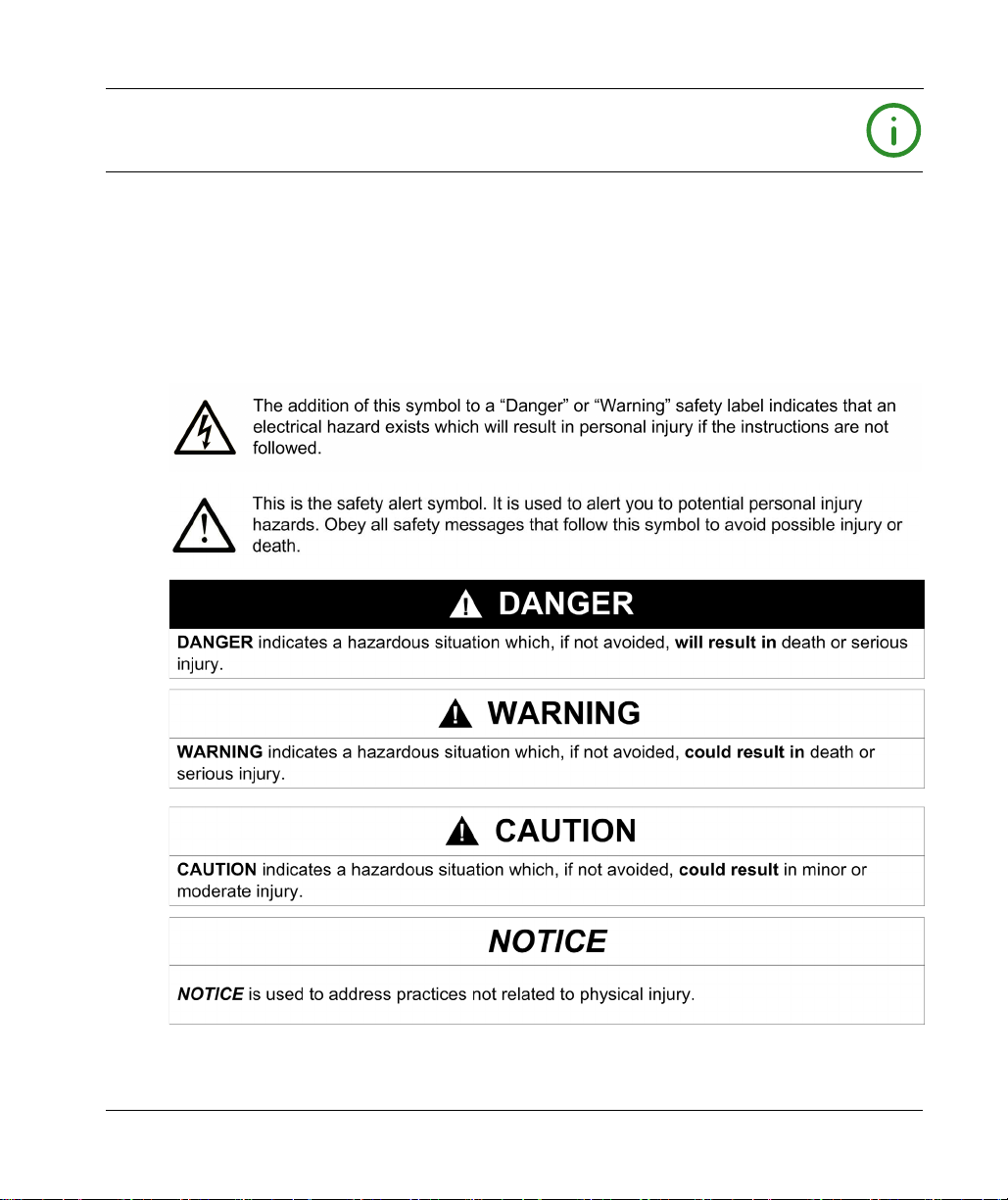
NOTICE
Read these instructions carefully, and look at the equipment to become familiar with the device
before trying to install, operate, service, or maintain it. The following special messages may appear
throughout this documentation or on the equipment to warn of potential hazards or to call attention
to information that clarifies or simplifies a procedure.
EIO0000001351 02/2020 7
Page 8

PLEASE NOTE
Electrical equipment should be installed, operated, serviced, and maintained only by qualified
personnel. No responsibility is assumed by Schneider Electric for any consequences arising out of
the use of this material.
A qualified person is one who has skills and knowledge related to the construction and operation
of electrical equipment and its installation, and has received safety training to recognize and avoid
the hazards involved.
8 EIO0000001351 02/2020
Page 9
About the Book
At a Glance
Document Scope
Read and understand the material contained in this manual before you work on Lexium 62 ILM
drive for the first time. Take particular note of the chapter
(see page 13)
(see page 20)
A copy of this manual must be available for personnel who work with the Lexium 62 ILM drive.
This manual is to help you use the capabilities of the Lexium 62 ILM drive safely and properly.
Follow the instructions within this manual to help:
Reduce risks
Reduce repair costs and downtime of the Lexium 62 ILM components.
Increase the service life of the Lexium 62 ILM components.
Increase reliability of the Lexium 62 ILM components.
Validity Note
This document has been updated for the release of EcoStruxureTM Machine Expert V1.2.
The technical characteristics of the devices described in the present document also appear online.
To access the information online, go to the Schneider Electric home page
electric.com
Specific Safety Information
. Only those persons who meet the criteria described in
are allowed to work with the Lexium 62 ILM components.
.
Qualification of Personnel
www.schneider-
Related Documents
Document title Reference
EcoStruxure Machine Expert Programming Guide
LXM62LT00A01000 Lexium 62 DC Link Terminal,
Instruction Sheet
SH3 Servo Motor - User Guide
EIO0000001351 02/2020 9
EIO0000002854 (ENG)
EIO0000002855 (FRE)
EIO0000002856 (GER)
EIO0000002857 (ITA)
EIO0000002858 (SPA)
EIO0000002859 (CHS)
NVE50846 (ENG)
0198441113987 (ENG)
;
;
Page 10

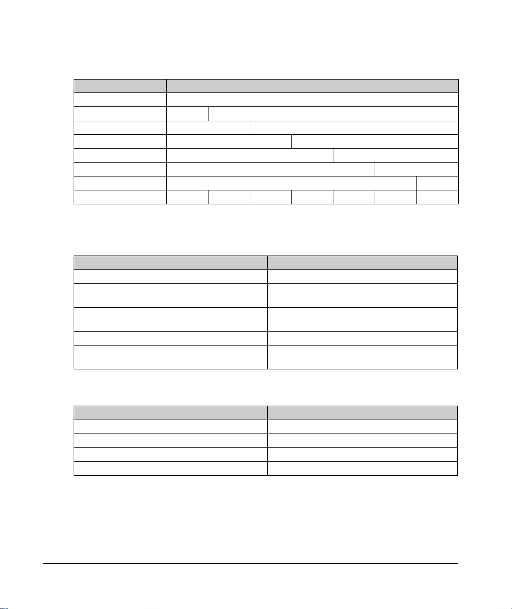
Terminology Derived from Standards
The technical terms, terminology, symbols and the corresponding descriptions in this manual, or
that appear in or on the products themselves, are generally derived from the terms or definitions
of international standards.
In the area of functional safety systems, drives and general automation, this may include, but is not
limited to, terms such as
safety, safety function, safe state, fault, fault reset, malfunction, failure
error, error message, dangerous
Among others, these standards include:
Standard Description
IEC 61131-2:2007 Programmable controllers, part 2: Equipment requirements and tests.
ISO 13849-1:2015 Safety of machinery: Safety related parts of control systems.
EN 61496-1:2013 Safety of machinery: Electro-sensitive protective equipment.
ISO 12100:2010 Safety of machinery - General principles for design - Risk assessment and risk
EN 60204-1:2006 Safety of machinery - Electrical equipment of machines - Part 1: General
ISO 14119:2013 Safety of machinery - Interlocking devices associated with guards - Principles
ISO 13850:2015 Safety of machinery - Emergency stop - Principles for design
IEC 62061:2015 Safety of machinery - Functional safety of safety-related electrical, electronic,
IEC 61508-1:2010 Functional safety of electrical/electronic/programmable electronic safety-
IEC 61508-2:2010 Functional safety of electrical/electronic/programmable electronic safety-
IEC 61508-3:2010 Functional safety of electrical/electronic/programmable electronic safety-
IEC 61784-3:2016 Industrial communication networks - Profiles - Part 3: Functional safety
2006/42/EC Machinery Directive
2014/30/EU Electromagnetic Compatibility Directive
2014/35/EU Low Voltage Directive
General principles for design.
Part 1: General requirements and tests.
reduction
requirements
for design and selection
and electronic programmable control systems
related systems: General requirements.
related systems: Requirements for electrical/electronic/programmable
electronic safety-related systems.
related systems: Software requirements.
fieldbuses - General rules and profile definitions.
,
, etc.
10 EIO0000001351 02/2020
Page 11
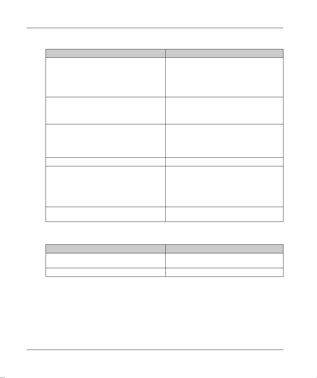
In addition, terms used in the present document may tangentially be used as they are derived from
other standards such as:
Standard Description
IEC 60034 series Rotating electrical machines
IEC 61800 series Adjustable speed electrical power drive systems
IEC 61158 series Digital data communications for measurement and control – Fieldbus for use in
industrial control systems
Finally, the term
hazards, and is defined as it is for a
2006/42/EC
(
zone of operation
) and
ISO 12100:2010
may be used in conjunction with the description of specific
hazard zone
or
danger zone
in the
Machinery Directive
.
NOTE: The aforementioned standards may or may not apply to the specific products cited in the
present documentation. For more information concerning the individual standards applicable to the
products described herein, see the characteristics tables for those product references.
EIO0000001351 02/2020 11
Page 12

12 EIO0000001351 02/2020
Page 13
Lexium 62 ILM
Specific Safety Information
EIO0000001351 02/2020
Specific Safety Information
Chapter 1
Specific Safety Information
Overview
This chapter contains important safety information regarding working with the Lexium 62 ILM.
What Is in This Chapter?
This chapter contains the following topics:
Product Related Information 14
Intended Use 18
Qualification of Personnel 20
Topic Page
EIO0000001351 02/2020 13
Page 14
Specific Safety Information
Product Related Information
Overview
Health and safety risks arising from the Lexium 62 ILM have been reduced. However residual risks
remain, since the Lexium 62 ILM components work with electrical voltage and electrical currents
as well as initiation of movement that may be hazardous depending on your machine design.
If activities involve residual risks, a safety message is made at the appropriate points. This includes
potential hazard(s) that may arise, their possible consequences, and describes preventive
measures to avoid the hazard(s).
Electrical Parts
ELECTRIC SHOCK, EXPLOSION, OR ARC FLASH
Disconnect all power from all equipment including connected devices prior to removing any
covers or doors, or installing or removing any accessories, hardware, cables, or wires.
Place a "Do Not Turn On" or equivalent hazard label on all power switches and lock them in
the non-energized position.
Wait 15 minutes to allow the residual energy of the DC bus capacitors to discharge.
Measure the voltage on the DC bus with a properly rated voltage sensing device and verify
that the voltage is less than 42.4 Vdc.
Do not assume that the DC bus is voltage-free when the DC bus LED is off.
Block the motor shaft to prevent rotation prior to performing any type of work on the drive
system.
Do not create a short-circuit across the DC bus terminals or the DC bus capacitors.
Replace and secure all covers, accessories, hardware, cables, and wires and confirm that a
proper ground connection exists before applying power to the unit.
Use only the specified voltage when operating this equipment and any associated products.
Failure to follow these instructions will result in death or serious injury.
DANGER
14
EIO0000001351 02/2020
Page 15
ELECTRIC SHOCK, EXPLOSION, OR ARC FLASH
Operate electrical components only with a connected protective ground (earth) cable.
After the installation, verify the secure connection of the protective ground (earth) cable to all
electrical devices to ensure that connection complies with the connection diagram.
Before enabling the device, safely cover the live components to prevent contact.
Do not touch the electrical connection points of the components when the module is
energized.
Provide protection against indirect contact.
Connect and disconnect cables and terminals only after you have verified that the power has
been removed from the system.
Failure to follow these instructions will result in death or serious injury.
Assembly and Handling
This product has a leakage (touch) current greater than 3.5 mA. If the protective ground connection
is interrupted, a hazardous leakage (touch) current may flow if the housing is touched.
INSUFFICIENT GROUNDING
Use a protective ground copper conductor with at least 10 mm
ground copper conductors with the same or larger cross section of the conductors supplying
the power terminals.
Verify compliance with all local and national electrical code requirements as well as all other
applicable regulations with respect to grounding of all equipment.
Failure to follow these instructions will result in death or serious injury.
DANGER
DANGER
Specific Safety Information
2
(AWG 6) or two protective
WARNING
CRUSHING, SHEARING, CUTTING AND HITTING DURING HANDLING
Observe the general construction and safety regulations for handling and assembly.
Use appropriate mounting and transport equipment and use appropriate tools.
Prevent clamping and crushing by taking appropriate precautions.
Cover edges and angles to protect against cutting damage.
Wear appropriate protective clothing (for example, protective goggles, protective boots,
protective gloves).
Failure to follow these instructions can result in death, serious injury, or equipment damage.
EIO0000001351 02/2020 15
Page 16
Specific Safety Information
Hazardous Movements
There can be different sources of hazardous movements:
No, or incorrect, homing of the drive
Wiring or cabling errors
Errors in the application program
Component errors
Error in the measured value and signal transmitter
NOTE: Provide for personal safety by primary equipment monitoring or measures. Do not rely only
on the internal monitoring of the drive components. Adapt the monitoring or other arrangements
and measures to the specific conditions of the installation in accordance with a risk and error
analysis.
UNAVAILABLE OR INADEQUATE PROTECTION DEVICE(S)
Prevent entry to a zone of operation with, for example, protective fencing, mesh guards,
protective coverings, or light barriers.
Dimension the protective devices properly and do not remove them.
Do not make any modifications that can degrade, incapacitate, or in any way invalidate
protection devices.
Before accessing the drives or entering the zone of operation, bring the drives and the motors
they control to a stop.
Protect existing workstations and operating terminals against unauthorized operation.
Position EMERGENCY STOP switches so that they are easily accessible and can be reached
quickly.
Validate the functionality of EMERGENCY STOP equipment before start-up and during
maintenance periods.
Prevent unintentional start-up by disconnecting the power connection of the drive using the
EMERGENCY STOP circuit or using an appropriate lock-out tag-out sequence.
Validate the system and installation before the initial start-up.
Avoid operating high-frequency, remote control, and radio devices close to the system
electronics and their feed lines, and perform, if necessary, an EMC validation of the system.
Failure to follow these instructions will result in death or serious injury.
DANGER
16
EIO0000001351 02/2020
Page 17
Drive systems may perform unanticipated movements because of incorrect wiring, incorrect
settings, incorrect data or other errors.
UNINTENDED MOVEMENT OR MACHINE OPERATION
Carefully install the wiring in accordance with the EMC requirements.
Do not operate the product with undetermined settings and data.
Perform comprehensive commissioning tests that include verification of configuration settings
and data that determine position and movement.
Failure to follow these instructions can result in death, serious injury, or equipment damage.
PELV Circuits
ELECTRIC SHOCK DUE TO INADEQUATE PROTECTIVE SEPARATION
Only connect devices, electrical components, or lines to the signal voltage connectors of these
products that feature a sufficient, protective separation from the connected circuits in accordance
with the standards (IEC 61800-5-1: Adjustable speed electrical power drive systems - safety
requirements).
Failure to follow these instructions will result in death or serious injury.
Specific Safety Information
WARNING
DANGER
EIO0000001351 02/2020 17
Page 18
Specific Safety Information
Intended Use
Installation
Install and operate this equipment in a control cabinet (enclosure) appropriately rated for its
intended environment and secured by a keyed or tooled locking mechanism.
The Lexium 62 ILM and the Lexium 62 Distribution Box are intended for the installation in a
machine.
Provide for Protective Measures
Before installing the device, provide for appropriate protective devices in compliance with local and
national standards. Do not commission components without appropriate protective devices. After
installation, commissioning, or repair, test the protective devices used.
Perform a risk evaluation concerning the specific use before operating the product and take
appropriate safety measures.
UNINTENDED EQUIPMENT OPERATION
Ensure that a risk assessment is conducted and respected according to EN/ISO 12100 during
the design of your machine.
Failure to follow these instructions can result in death, serious injury, or equipment damage.
WARNING
18
If circumstances occur that affect the safety or cause changes to the operating behavior of the
Lexium 62 ILM components, then immediately shut down the Lexium 62 ILM components and
contact your Schneider Electric representative.
EIO0000001351 02/2020
Page 19
Use Original Equipment Only
Use only the accessories and mounting parts specified in the documentation and no third-party
devices or components that have not been expressly approved by Schneider Electric.
There are no user-serviceable parts in the Lexium 62 ILM system. Do not attempt to modify the
Lexium 62 ILM in any way. Refer to Schneider Electric for all repairs and replacements.
UNINTENDED EQUIPMENT OPERATION
Only use software and hardware components approved by Schneider Electric for use with this
equipment.
Do not attempt to service this equipment outside of authorized Schneider Electric service
centers.
Update your application program every time you change the physical hardware configuration.
Failure to follow these instructions can result in death, serious injury, or equipment damage.
Environment Restrictions
The components must not be used in the following environments:
In hazardous (explosive) atmospheres
In mobile, movable, or floating systems
In life support systems
In domestic appliances
Underground
This equipment has been designed to operate outside of any hazardous location. Only install this
equipment in zones known to be free of a hazardous atmosphere.
Specific Safety Information
WARNING
DANGER
POTENTIAL FOR EXPLOSION
Install and use this equipment in non-hazardous locations only.
Failure to follow these instructions will result in death or serious injury.
EIO0000001351 02/2020 19
Page 20

Specific Safety Information
Qualification of Personnel
Target Audience for This Manual
Electrical equipment must be installed, operated, serviced, and maintained only by qualified
personnel. No responsibility is assumed by Schneider Electric for any consequences arising out of
the use of this material.
Qualified Person
A qualified person is one who has skills and knowledge related to the construction and operation
of electrical equipment and the installation, and has received safety training to recognize and avoid
the hazards involved.
The qualified personnel must be able to detect possible hazards that may arise from parameterization, changing parameter values and generally from mechanical, electrical, or electronic
equipment. The qualified personnel must be familiar with the standards, provisions, and
regulations for the prevention of industrial accidents, which they must observe when working on
the drive system.
Designated Safety Functions
Qualified personnel that work with designated safety functions must be trained according to the
complexity of the machines and the requirements of the ISO 13849-1. The training has to include
the production process and the relation between the designated safety function and the machine.
Qualification guidelines are available in the following publication:
Commitment: Competency Guidelines for Safety-Related System Practitioners
IEEE Publications, ISBN 0 85296 787 X, 1999.
Safety, Competency and
.
20
EIO0000001351 02/2020
Page 21
Lexium 62 ILM
System Overview
EIO0000001351 02/2020
System Overview
Chapter 2
System Overview
What Is in This Chapter?
This chapter contains the following topics:
System Overview 22
Lexium 62 Power Supply 24
Lexium 62 Connection Module 27
Lexium 62 Distribution Box 29
Lexium 62 ILM Integrated Servo Drive 31
Lexium 62 ILM Digital I/O Module 34
Lexium 62 ILM Safety Module 36
ILM Daisy Chain Connector Box 38
Topic Page
EIO0000001351 02/2020 21
Page 22
System Overview
System Overview
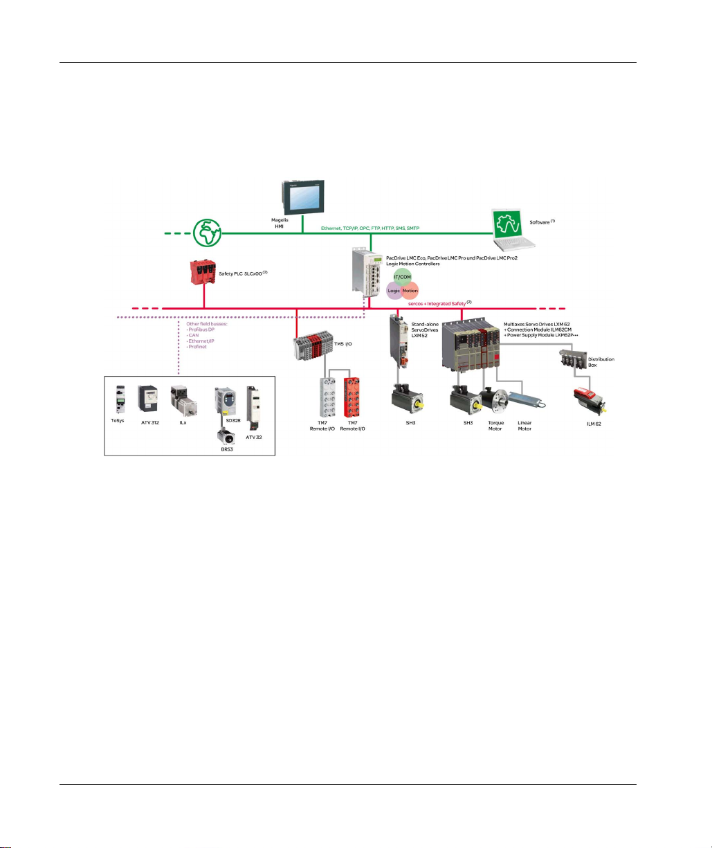
System Overview
The control system consists of several components, depending on its application.
PacDrive 3 system overview:
22
(1) EcoStruxure Machine Expert Software
(2) Safety Logic Controller according to IEC 61508:2010 and EN ISO 13849:2008
EIO0000001351 02/2020
Page 23
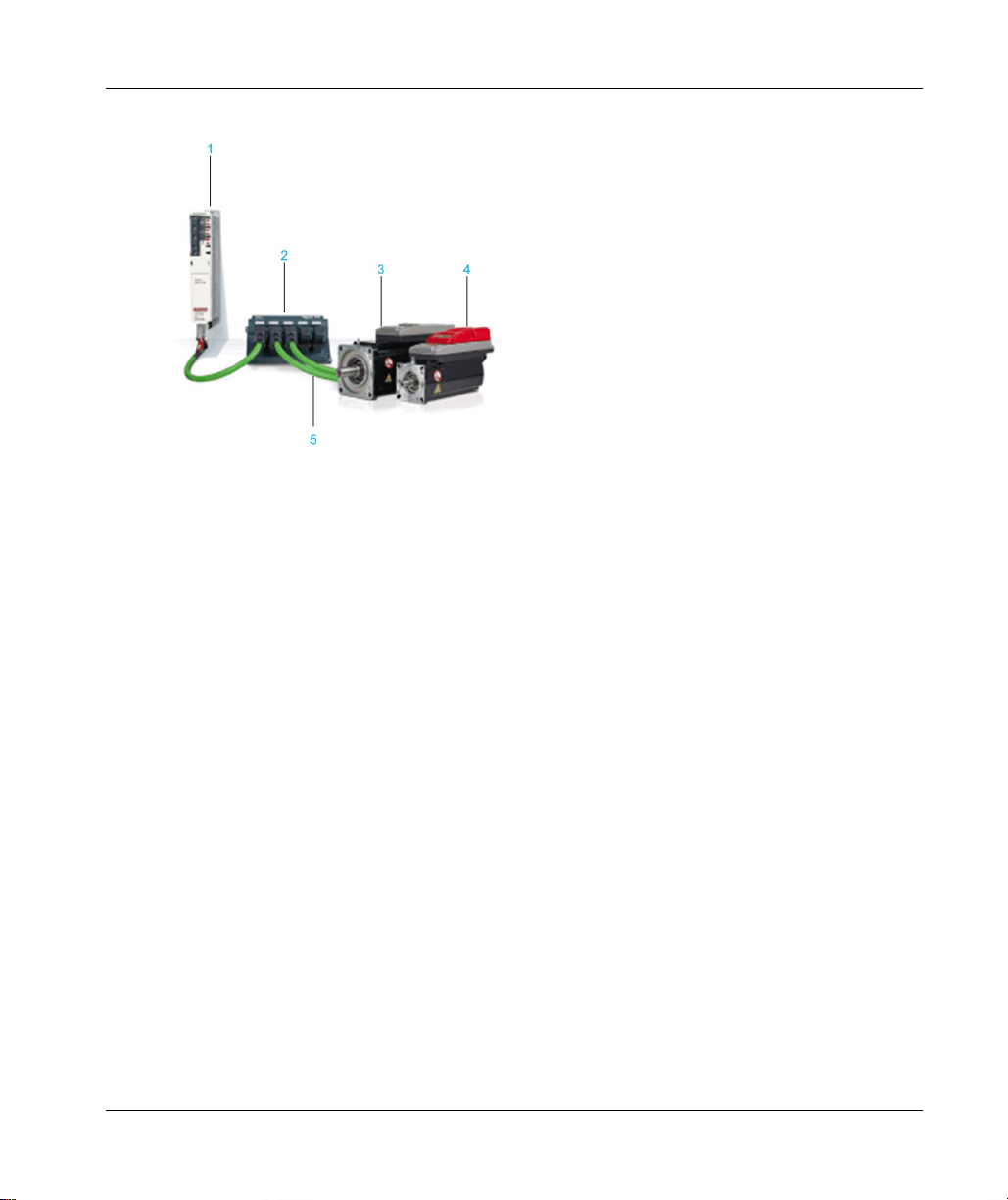
Lexium 62 ILM system overview:
1 Lexium 62 Connection Module
2 Lexium 62 Distribution Box
3 Lexium 62 ILM Integrated Servo Drive
4 Lexium 62 ILM with Safety Module
5 Hybrid Cable
System Overview
EIO0000001351 02/2020 23
Page 24
System Overview
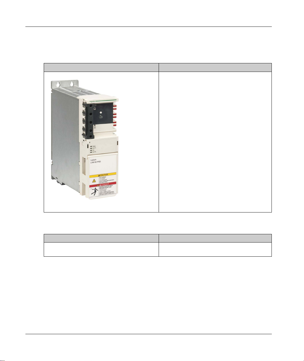
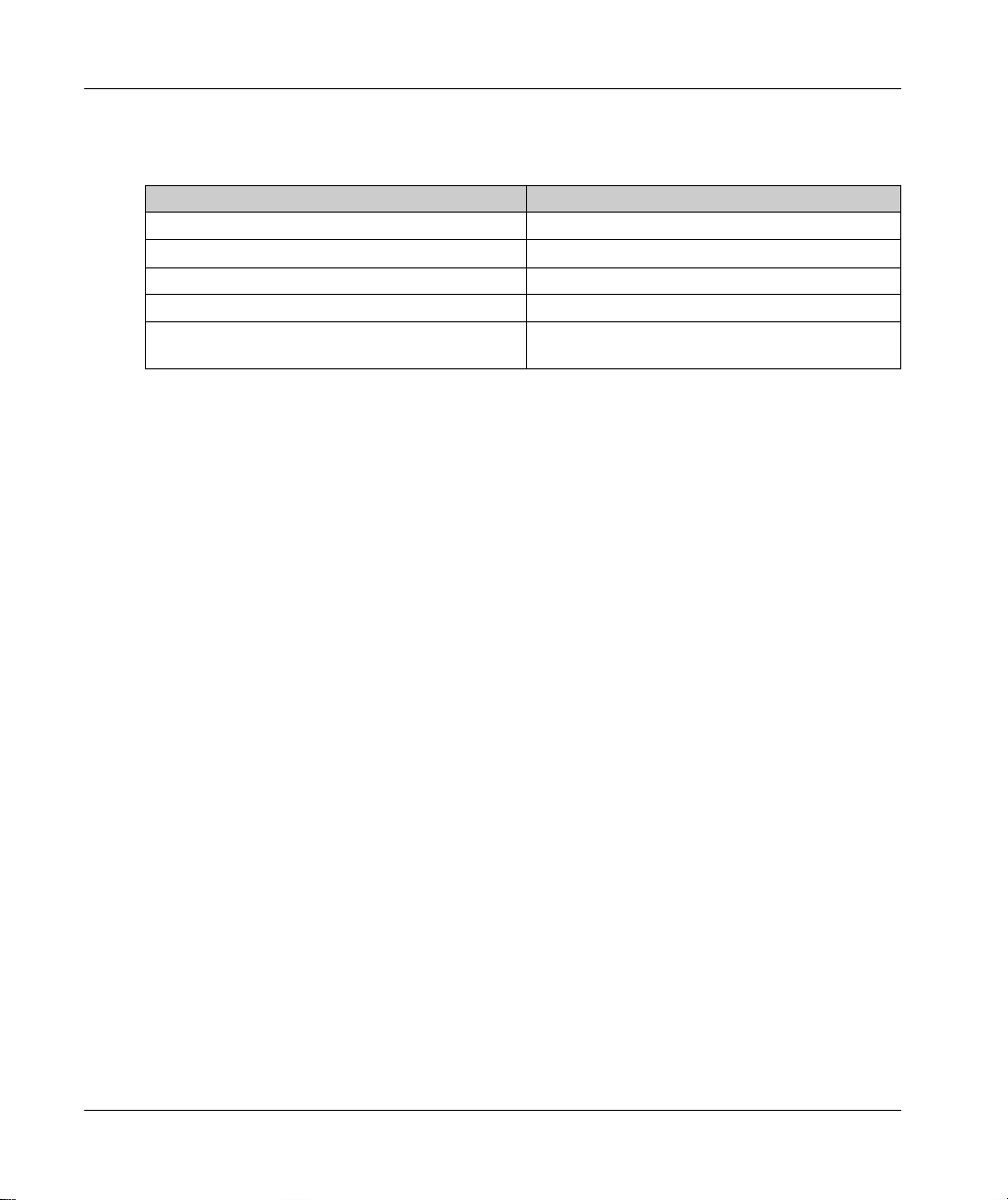
Lexium 62 Power Supply
Overview
Product Description
The central Lexium 62 Power Supply, using a
common DC bus, supplies the connected Lexium 62
servo drive(s) with the required power.
For further information, refer to:
Installation and Maintenance (see page 97)
Indicators of the Lexium 62 Power Supply
(see page 150)
Electrical Connections for the Lexium 62 Power
Supply (see page 162)
Mechanical and Electrical Data for the Lexium 62
Power Supply (see page 188)
References
Product Reference
Power supply LXM62PD20A11000
24
LXM62PD84A11000
EIO0000001351 02/2020
Page 25
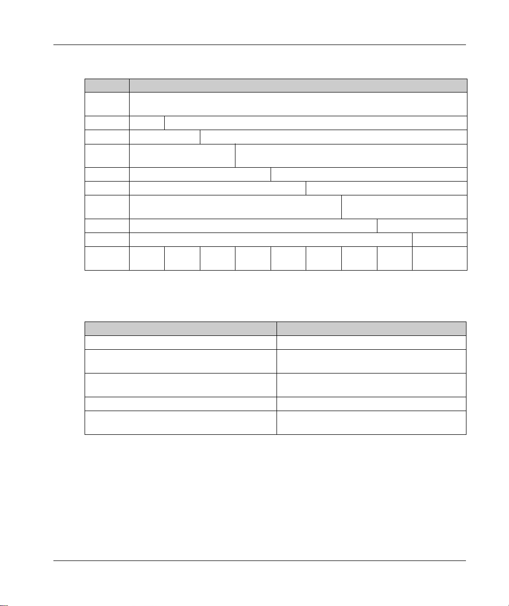
Type Code
Item Meaning
Product
family
Size 62 = Lexium 62
Type P = Power Module
Peak
current
Variants A = Power Supply Module
Options 1 = 1 or 3 Phases x 208...480 Vac
Hardware
release
Internal 0 = Serial production
Customer 00 = Standard
Type code
(example)
Technical Nameplate
The technical nameplate is located laterally on housing.
System Overview
LXM = Lexium
D84 = 84 A
D20 = 20 A
1
LXM 62 P D84 A 1 1 0 00
Label Meaning
LXM62PDxxxxxxx Device type and Unicode
Input ac/dc Input voltage and/or input current (rated- and/or peak
Output dc Output voltage and output current (rated and/or peak
IP20 Degree of protection
Symbols This field displays the symbols of declarations and
EIO0000001351 02/2020 25
value per input)
value per output)
certifications
Page 26
System Overview
Logistic Nameplate
The technical nameplate is located on top of the housing.
Label Meaning
LXM62PDxxxxxxx Device type and Unicode
2528044067 Serial number
RS:01 Hardware revision
DOM Date of manufacture
Symbols This field displays the symbols of declarations and
certifications
26
EIO0000001351 02/2020
Page 27
Lexium 62 Connection Module
Overview
The Lexium 62 Connection Module simplifies the wiring of the devices. With the
Lexium 62 Connection Module you can connect up to 45 servo drives.
Product Description
System Overview
The Lexium 62 Connection Module supplies the
Lexium 62 ILMs with DC voltage from the DC bus via a
hybrid cable or a power cable (daisy chain wiring).
Additionally, the Lexium 62 Connection Module provides the
Inverter Enable and Sercos interface.
For further information, refer to:
Installation and Maintenance (see page 97)
Indicators of the Lexium 62 Connection Module
(see page 153)
Electrical Power Connection of the Lexium 62
Connection Module (see page 168)
Mechanical and Electrical Data for the Lexium 62
Connection Module (see page 191)
References
Product Reference
Lexium 62 Connection Module ILM62CMD20A000
EIO0000001351 02/2020 27
Page 28
System Overview
Type Code
Item Meaning
Product family ILM = Integrated Lexium Servo Module
Size 62 = Lexium 62
Type CM = Connection Module
Power
(cont. DC Bus
current)
Variants A
Internal 0 = Serial production
Customer 00 = Standard
Type code
(example)
Technical Nameplate
The technical nameplate is located laterally on housing.
Label Meaning
ILM62CMxxxxxxx Device type and Unicode
Input dc Input voltage and/or input current (rated- and/or peak
Output ac/dc Output voltage and output current (rated and/or peak
IP20 Degree of protection
Symbols This field displays the symbols of declarations and
D20
ILM 62 CM D20 A 0 00
value per input)
value per output)
certifications
Logistic Nameplate
The technical nameplate is located on top of the housing.
Label Meaning
ILM62xxxxxxxxxx Device type and Unicode
2528044067 Serial number
RS:01 Hardware revision
DOM Date of manufacture
Symbols This field displays the symbols of declarations and
28
certifications
EIO0000001351 02/2020
Page 29
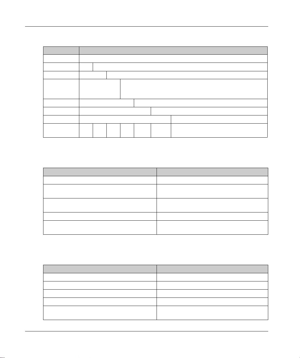
Lexium 62 Distribution Box
Overview
Product Description
The highlights:
1...4 connections for Lexium 62 ILMs or daisy chain lines or further Lexium 62 distribution
boxes.
Pre-assembled hybrid cables or power cables (Daisy Chain wiring).
System Overview
The Lexium 62 Distribution Box is the link between
Lexium 62 Connection Module and Lexium 62 ILM.
Depending on the number of drives, 1 to 4
Lexium 62 ILMs or daisy chain lines can be
connected. When operating more than four drives,
expand the system by using more Lexium 62
distribution boxes.
For further information, refer to:
Installation and Maintenance (see page 97)
Indicators of the Lexium 62 Distribution Box
(see page 155)
Electrical Connections for the Lexium 62
Distribution Box (see page 174)
Mechanical and Electrical Data for the Lexium 62
Distribution Box (see page 194)
References
Product Reference
Lexium 62 Distribution Box ILM62DB4A000
Sercos bridge plug VW3E6023
EIO0000001351 02/2020 29
Page 30
System Overview
Type Code
Item Meaning
Product family ILM = Integrated Lexium Servo Module
Size 62 = Lexium 62
Type DB = Distribution Box
Hybrid outputs 4
Variants A
Internal 0
Customer 0
Type code (example) ILM 62 DB 4 A000
Technical Nameplate
The technical nameplate is located laterally on housing:
Label Meaning
ILM62DBxxxxx Device type and Unicode
Input dc Input voltage and/or input current (rated- and/or peak
Output ac/dc Output voltage and output current (rated and/or peak
IP65 Degree of protection
Symbols This field displays the symbols of declarations and
value per input)
value per output)
certifications
Logistic Nameplate
Label Meaning
ILM62DBxxxxx Device type and Unicode
2328234578 Serial number
RS:01 Hardware revision
DOM Date of manufacture
30
EIO0000001351 02/2020
Page 31

Lexium 62 ILM Integrated Servo Drive
Overview
Product Description
The Lexium 62 ILMs are available in three different flange sizes:
ILM070 (70 mm / 2.76 in.)
ILM100 (100 mm / 3.94 in.)
ILM140 (140 mm / 5.51 in.)
The Lexium 62 ILMs have been derived from the Schneider Electric SH3 family of motors, and
therefore share many characteristics. For instance, when it comes to mounting the motor, the
Lexium 62 ILMs are equivalent.
The highlights:
Compact design
3.5 times peak torque
Integrated Sercos interface
High-resolution single or multi-turn encoder
Degree of protection IP65 (depending on the reference and/or options)
System Overview
The Lexium 62 ILM combines motor, power stage,
and digital servo controller for an axis in a spacesaving housing. Due to its compact design with the
integrated drive, it is suitable for decentralized,
distributed architectures. It is available with singleturn or multi-turn encoders, and simplifies
configuration with the aid of the electronic nameplate
in the Lexium 62 ILM.
For further information, refer to:
Installation and Maintenance (see page 98)
Indicators of the Lexium 62 ILM Integrated Servo
Drive (see page 157)
Electrical Connections for the Lexium 62 ILM
Integrated Servo Drive (see page 177)
Mechanical and Electrical Data for the Lexium 62
ILM Integrated Servo Drive (see page 202)
EIO0000001351 02/2020 31
Page 32

System Overview
References
Device Reference
Lexium 62 ILM Integrated Servo Drive
Type Code
Item Meaning
Product family ILM = Integrated Lexium Servo Module
Flange size 070 = 70 mm / 2.76 in.
Number of
stacks
Winding type P = Standard
Shaft
(see page 215)
Encoder
(see page 214)
Holding brake
(see page 217)
Variants 0
Internal 0 = Standard production
Costumer 00 = Standard
Type code
(example)
ILM0701P
ILM0702P
ILM0703P
ILM1001P
ILM1002P
ILM1003P
ILM1401P
ILM1401M
ILM1402P
100 = 100 mm / 3.94 in.
140 = 140 mm / 5.51 in.
1 = 1 Stack
2 = 2 Stacks
3 = 3 Stacks
M = Optimized in terms of torque (available only with ILM1401)
0 = Smooth shaft, without shaft seal
1 = Parallel key, without shaft seal
2 = Smooth shaft, with shaft seal, IP65
3 = Parallel key, with shaft seal, IP65
1 = Absolute single-turn 128 SinCos periods per
revolution
2 = Absolute multi-turn 128 SinCos periods per revolution
A = Without holding brake
F = With holding brake
ILM 070 1 P 0 1 A 0 0 00
32
EIO0000001351 02/2020
Page 33

Technical/Logistic Nameplate
Label Meaning
ILMxxxxxxxxxxxx Device type, see type code
SN Serial number
Input 1 Rated voltage and rated current of the power supply
Input 2 Rated voltage and rated current of the electronics
Type rating Degree of protection of the housing in accordance with NEMA 250 and
HW Hardware version
SW Software version
IPxx Degree of protection
Th-Cl Insulation material class of the motor
M0 Standstill torque
Mmax Peak torque
nN Nominal speed of rotation
DOM Date of manufacture
Symbols This field displays the symbols of declarations and certifications.
System Overview
UL 50.
EIO0000001351 02/2020 33
Page 34

System Overview
Lexium 62 ILM Digital I/O Module
Overview
Option Module for Lexium 62 ILM Integrated Servo Drive.
Product Description
Reference
Product Reference
Digital I/O Module VW3E702100000
Type Code
Lexium 62 ILM Digital I/O Module with 8 digital inputs
or outputs.
For further information, refer to the chapter
ILM 62 Digital I/O Module (see page 227)
Lexium
.
Item Meaning
Product family VW3 = Integrated Lexium
Size E = PacDrive 3
Type 7 = Option Modules
Drawing reference 021 = I/O Option Module for
Internal 00000
Type code (example) VW3 E 7 021 00000
34
Lexium 62 ILM
022 = Safety Option Module for
Lexium 62 ILM
EIO0000001351 02/2020
Page 35

Technical/Logistic Nameplate Description
Label Meaning
ILM62-iSH-DIO8 I/O module Device type and Unicode
VW3E702100000 Commercial reference
2910229412 Serial number
DOM Date of manufacture
HW Hardware version
FW Firmware version
System Overview
EIO0000001351 02/2020 35
Page 36

System Overview
Lexium 62 ILM Safety Module
Overview
Option module for Lexium 62 ILM integrated servo drive.
Product Description
Reference
Product Reference
Safety Module VW3E702200000
Lexium 62 ILM Safety Module manages the safe
motion functions via Sercos bus.
Safe Torque off (STO)
Safe Stop 1 (SS1)
Safe Operating Stop (SOS)
Safe Stop 2 (SS2)
Safe Maximum Speed (SMS)
Safely-Limited Speed (SLS)
Safe Direction Indication (SDI)
For further information, refer to the chapter
62 ILM Safety Module (see page 239)
Lexium
.
Type Code
Item Meaning
Product family VW3 = Integrated Lexium
Size E = PacDrive 3
Type 7 = Option Modules
Drawing reference 021 = I/O Option Module for
Lexium 62 ILM
022 = Safety Option Module for
Lexium 62 ILM
Internal 00000
Type code (example) VW3 E 7 022 00000
36
EIO0000001351 02/2020
Page 37

Technical/Logistic Nameplate Description
Label Meaning
Lexium 62 ILM safety option module Device type and Unicode
VW3E702200000 Commercial reference
2910171253 Serial number
DOM Date of manufacture
HW Hardware version
FW Firmware version
System Overview
EIO0000001351 02/2020 37
Page 38

System Overview
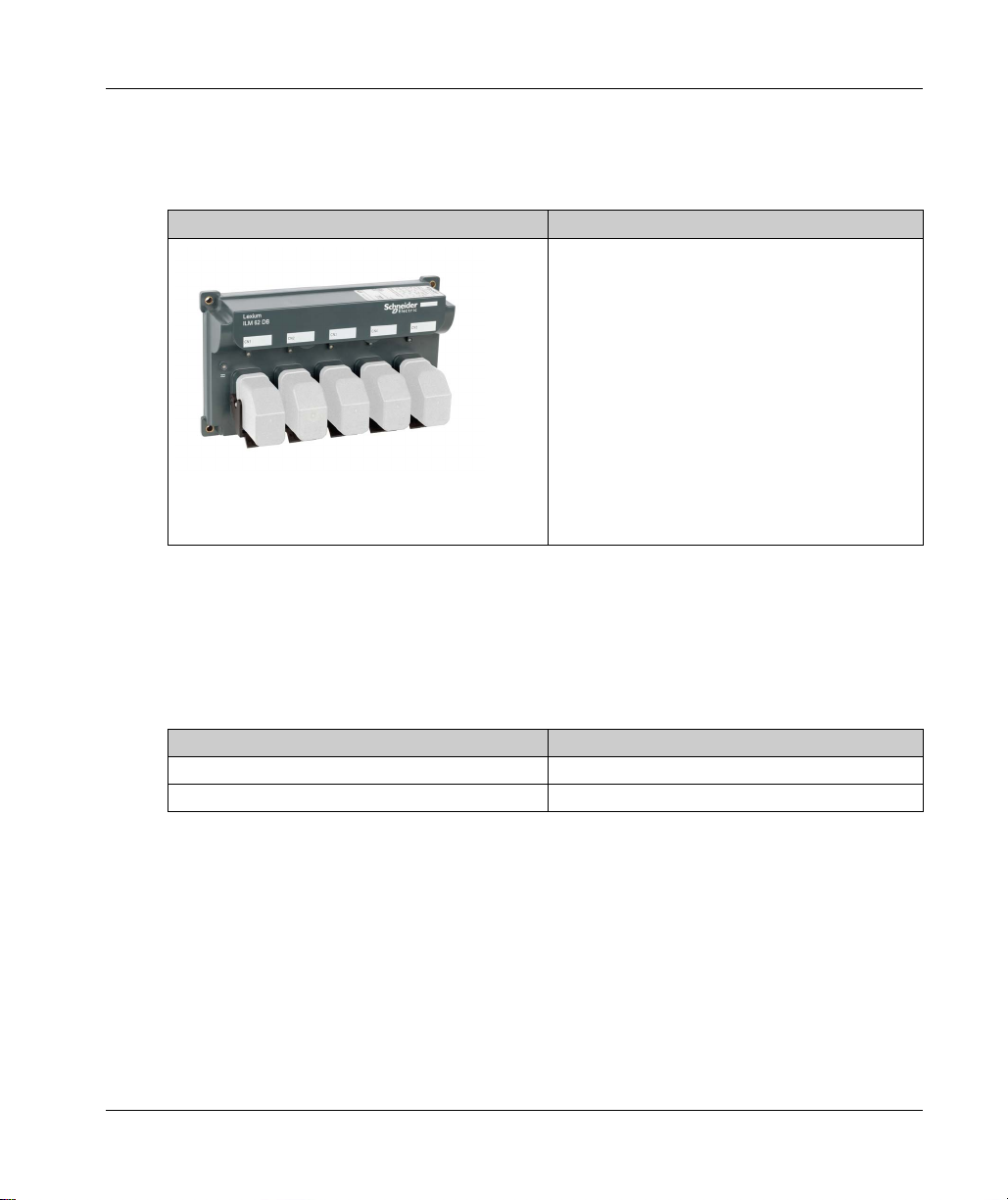
ILM Daisy Chain Connector Box
Overview
Product Description
Type A The ILM Daisy Chain Connector Box is mounted on
Type B Power (DC bus voltage/24 V/Inverter Enable signals)
Type C
a Lexium 62 ILM in order to enable a daisy chain
wiring.
The Lexium 62 ILMs can be either directly connected
to the Lexium 62 Distribution Box or via a
Lexium 62 Connection Module. Refer to
Wiring from
the Lexium 62 Connection Module in a Daisy Chain
Topology (see page 120)
When connecting via a Lexium 62 Distribution Box, a
larger number of drives can be connected.
and Sercos signals are distributed via separate
cables. Each Lexium 62 ILM must be extended by a
Daisy Chain Connector Box (refer to
(see page 108)
Box is used, then up to four daisy chain lines can be
connected to it. If several Lexium 62 distribution
boxes are used, then from the first
Lexium 62 Distribution Box up to and including the
second last Lexium 62 Distribution Box respectively
up to three daisy chain lines and on the last
Lexium 62 Distribution Box up to four daisy chain
lines can be connected. A daisy chain line can
consist of up to nine Lexium 62 ILMs.
). If only one Lexium 62 Distribution
.
Mounting
38
EIO0000001351 02/2020
Page 39

For further information, refer to:
The connection between the Lexium 62 ILMs is established as follows (refer to Wiring from the
Lexium 62 Connection Module in a daisy chain topology
Power cable for power distribution (DC bus voltage/24V/Inverter Enable signals) with an M23
Sercos cable for distribution of the Sercos signals via M12 connector
Reference
Product Reference
ILM Daisy Chain Connector Box
Type Code
Item Meaning
Product
family
Size 62 = Integrated Lexium 62
Type DC = Daisy Chain Connector Box
Series A = Power at back, Sercos at bottom (ILM070, ILM100,
Internal 0 = Serial production
Customer 00 = Standard
Type code
(example)
System Overview
Electrical Connections for the ILM Daisy Chain Connector Box (see page 179)
Mechanical and Electrical Data for the ILM Daisy Chain Connector Box (see page 197)
(see page 120)
):
connector
ILM62DCA000
ILM62DCB000
ILM62DCC000
ILM = Integrated Lexium Servo Module
ILM140)
B = Power at bottom, Sercos at left and right (ILM070)
C = Power at bottom, Sercos at left and right (ILM100)
Z = Protection cap for the last M23 connector
ILM 62 DC A 0 00
EIO0000001351 02/2020 39
Page 40

System Overview
40
EIO0000001351 02/2020
Page 41

Lexium 62 ILM
Engineering
EIO0000001351 02/2020
Engineering
Chapter 3
Engineering
What Is in This Chapter?
This chapter contains the following sections:
Section Topic Page
3.1 Electromagnetic Compatibility, EMC 42
3.2 Control Cabinet Planning 46
3.3 Information about Wiring 51
3.4 Functional Safety 66
3.5 Special Conditions 93
EIO0000001351 02/2020 41
Page 42

Engineering
Electromagnetic Compatibility, E MC
Section 3.1
Electromagnetic Compatibility, EMC
Electromagnetic Compatibility, EMC
Electromagnetic Disturbances of Signals and Devices
This product meets the EMC requirements according to the standard IEC 61800-3 if the measures
described in this manual are implemented during installation.
Signal interference can cause unexpected responses of the drive and of other equipment in the
vicinity of the drive.
WARNING
SIGNAL AND EQUIPMENT INTERFERENCE
Only operate the drive with the specified external mains filter.
Install the wiring in accordance with the EMC requirements described in the present
document.
Verify compliance with the EMC requirements described in the present document.
Verify compliance with all EMC regulations and requirements applicable in the country in
which the product is to be operated and with all EMC regulations and requirements applicable
at the installation site.
Failure to follow these instructions can result in death, serious injury, or equipment damage.
42
WARNING
ELECTROMAGNETIC DISTURBANCES OF SIGNALS AND DEVICES
Use proper EMC shielding techniques to help prevent unintended device operation in accordance
with the standard IEC 61800-3.
Failure to follow these instructions can result in death, serious injury, or equipment damage.
EIO0000001351 02/2020
Page 43

These types of devices are not intended to be used on a low-voltage public network which supplies
domestic premises. Radio frequency interference is expected if used in such a network.
RADIO INTERFERENCE
Do not use these products in domestic electrical networks.
Failure to follow these instructions can result in death, serious injury, or equipment damage.
Layout Control Cabinet (Enclosure)
The prerequisite for compliance with the specified limit values is an EMC compatible layout.
Depending on the application, the following measures can improve the EMC-dependent values:
EMC measures Objective
Use galvanized or chromium-plated sub plates, bond
metallic parts across large surface areas, remove
paint layer from contact surfaces.
Ground control cabinet (enclosure), door, and sub
plates by using grounding strips or grounding cables
with a cross-section of 10 mm
Supplement switch devices such as contactors,
relays, or magnetic valves with interference
suppression combinations or spark suppressor
elements (for example, diodes, varistors, RC
elements).
Fit power and control components separately. Reduces mutual interference.
2
(AWG 6).
Engineering
WARNING
Good conductivity by surface area contact.
Reduce emission.
Reduces mutual interference.
Shielded Cables
EMC measures Objective
Connect large surface areas of cable shields, use
cable clamps and ground straps.
Ground shields of digital signal wires at both ends by
connecting them to a large surface area or via
conductive connector housings.
Ground shield of analog signal cables directly on the
device (signal input), insulate the shield at the other
cable end or ground the same through a capacitor,
such as 10 nF.
EIO0000001351 02/2020 43
Reduce emission.
Reduce interference action on signal cables, reduce
emissions.
Reduce grounding loops by low frequency
interferences.
Page 44
Engineering
Cable Installation
EMC measures Objective
Do not route fieldbus cables and signal wires in a
single cable duct together with lines with DC and AC
voltages of more than 60 V. (Fieldbus cables, signal
lines, and analog lines may be in the same cable duct)
Recommendation: Use separate cable ducts at least
20 cm (7.84 in) apart.
Keep cables as short as possible. Do not install
unnecessary cable loops, use short cables from the
central grounding point in the control cabinet to the
external ground connection.
Use equipotential bonding conductors (stranded wire
of equal potential at all grounding locations connected
to an equipotential grounding plane) in the following
cases: wide-area installations, different voltage
supplies, and installation across several buildings.
Use stranded wire potential equalization conductor. Discharging of high frequency interference currents.
If motor and machine are not connected in a
conducting fashion, for example, due to an insulated
flange or a connection not across a full surface, the
motor must be grounded via a grounding cable with a
minimum 4 mm
grounding strip with a length as short as possible.
Use twisted pair for 24 Vdc signals. Reduce interference action on signal cables, reduce
2
(AWG 11) cross-section or a
Reduces mutual interference.
Reduces capacitive and inductive interference.
Reduces current in the cable shield, reduces
emissions.
Reduce emissions, increase interference resistance.
emissions.
Power Supply
EMC measures Objective
Operate product on mains with grounded neutral
point.
Use surge arrester if there is a risk of overvoltage. Reduces the risk of damage caused by overvoltage.
44
Enables effectiveness of mains filter.
EIO0000001351 02/2020
Page 45

Additional Measures for Improving the EMC
Depending on the respective application, the following measures may lead to an EMC compatible
layout:
EMC measures Objective
Upstream connection of mains line reactor (choke) Reduction of the harmonic network oscillations,
Upstream connection of external mains filters Improvement of the EMC limit values.
Special EMC-appropriate layout, for example, within
an enclosed control cabinet complete with 15 dB
attenuation of the interferences emitted
Engineering
extension of the service life of the product.
Improvement of the EMC limit values.
EIO0000001351 02/2020 45
Page 46

Engineering
Control Cabinet Planning
Section 3.2
Control Cabinet Planning
What Is in This Section?
This section contains the following topics:
Degree of Protection (IP) 47
Mechanical and Climatic Environmental Conditions in the Control Cabinet 48
Using Cooling Units 49
Topic Page
46
EIO0000001351 02/2020
Page 47

Degree of Protection (IP)
Overview
Install components such that a degree of protection corresponding to the actual operational
environment is set up.
For more information on the degree of protection of the component, refer to
(see page 187)
The following ambient conditions may damage the components:
Oil
Moisture
Electromagnetic interference
Ambient temperature
Metal dust deposits
UNINTENDED EQUIPMENT OPERATION
Observe and conform to ambient temperatures, storage temperatures and transport
temperatures of the individual components as specified in the operating manuals of the
components.
Prevent the formation of moisture during the operation, storage and transport of individual
components.
Conform to the vibration and shock requirements specified in the operating manuals for the
components when operating, storing and transporting system components.
Failure to follow these instructions can result in death, serious injury, or equipment damage.
.
Engineering
Ambient Conditions
WARNING
EIO0000001351 02/2020 47
Page 48

Engineering
Mechanical and Climatic Environmental Conditions in the Control Cabinet
Overview
Step Action
1 Observe the climatic and mechanical ambient conditions.
For more information on the general climatic and mechanical environmental conditions
according to IEC 60721, refer to
2 Verify the technical data of the device whether the permitted deviations (for example, higher
shock load or higher temperature) are specified.
Ambient Conditions (see page 187)
.
48
EIO0000001351 02/2020
Page 49

Using Cooling Units
Installing a Cooling Unit
How to proceed when installing a cooling unit:
Step Action
1 Position the cooling units so that no condensate drips out of the cooling unit onto electronic
components or is sprayed by the cooling air flow.
2 Provide specially designed control cabinets for cooling units on the top of the control cabinet.
3 Design the control cabinet so that the cooling unit fan cannot spray any accumulated condensate
onto the electronic components when it restarts after a pause.
4 When using cooling units, use only well-sealed control cabinets so that warm, humid outside air,
which causes condensation, does not enter the cabinet.
5 When operating control cabinets with open doors during commissioning or maintenance, ensure
that the electronic components are at no time cooler than the air in the control cabinet after the
doors are shut, in order to avoid any condensation.
6 Continue to operate the cooling unit even when the system is switched off, so that the
temperature of the air in the control cabinet and the air in the electronic components remains the
same.
7 Set cooling unit to a fixed temperature of 40 °C or lower (104 °F).
8 For cooling units with temperature monitoring, set the temperature limit to 40 °C (104 °F) so that
the internal temperature of the control cabinet does not fall below the external air temperature.
Engineering
WARNING
UNINTENDED EQUIPMENT OPERATION
Follow the installation instructions such that the condensation from the cooling unit can not enter
electrical equipment.
Failure to follow these instructions can result in death, serious injury, or equipment damage.
EIO0000001351 02/2020 49
Page 50

Engineering
Installing a cooling unit
50
EIO0000001351 02/2020
Page 51

Information about Wiring
Section 3.3
Information about Wiring
What Is in This Section?
This section contains the following topics:
General Information about Wiring 52
Cable Characteristics 53
ESD Protection Measures 55
Conditions for UL / CSA Compliant Use 56
Fusing the Mains Connection 58
Mains Contactor 60
Mains Filter 61
Mains Line Reactor (Choke) 62
Connection of the Lexium 62 Power Supply 63
Leakage (Touch) Current 64
Residual Current Operated Protective Device 65
Engineering
Topic Page
EIO0000001351 02/2020 51
Page 52

Engineering
General Information about Wiring
Overview
Use only Schneider Electric approved devices in your application, and especially Schneider
Electric pre-fabricated cables, wherever and whenever possible.
For further information, refer to
Use an appropriate torque indication or screwdriver for tightening connections.
Observe and implement the following points when wiring:
1. Observe the minimum cross-sections of the cables necessary for the load carrying capacity of
the equipment being connected.
2. Verify the integrity of cable shields to ensure continuity to ground.
3. Ensure that there is a proper, equipotential connection to ground for all interconnected
equipment.
4. Ensure connection of the motors to the machine ground.
5. Eliminate any ground loops.
6. Do not disconnect cable connection terminals when under power.
7. Ensure that all ground connections have sufficient surface area continuity.
8. Do not interchange motor phases.
9. Do not interchange encoder connections.
10.Connect the hybrid or power cable connections and the Sercos cable connections to the
Lexium 62 Connection Module according to the connection diagram of the machine
manufacturer.
For information on the different cable type refer to
11.Do not interchange the emergency stop circuits. This has to be observed especially when two
different safety-related circuits are used for axis A and axis B of the Lexium 62 Double Drive.
If, for example, two parallel conductors are shown as coming from one point, you may not run just
one conductor and then branch it off at a later point. If it is wired this way, induction loops
(interference emitters and antennas) as well as interfering potential shifts may occur.
Cable Characteristics (see page 53)
Cable Characteristics (see page 53)
.
.
52
DANGER
INCORRECT OR UNAVAILABLE GROUNDING
Remove paint across a large surface at the installation points before installing the devices (bare
metal connection).
Failure to follow these instructions will result in death or serious injury.
EIO0000001351 02/2020
Page 53

Cable Characteristics
Overview
Cable characteristics of the hybrid cable:
Property Value
Hybrid cable voltage isolation 1000 V
Maximum continuous current
Temperature range -40...+80 °C / -40...+176 °F
Cable diameter 14.8 ± 0.3 mm (0.58 ± 0.012 in.)
Bending radius Five x diameter (fixed routing)
Sheath PUR, oil resistant, halogen-free
The hybrid cable (daisy chain wiring) is drag chain capable.
Cable characteristics of the power cable (daisy chain wiring):
Property Value
Voltage isolation 1000 V
Maximum continuous current
Temperature range -40...+80 °C / -40...+176 °F (fixed routing)
Cable diameter 11.7 ± 0.3 mm (0.45 ± 0.012 in.)
Bending radius 5 x diameter (fixed routing)
Sheath PUR, oil resistant, halogen-free, flame-retardant
Engineering
DC Bus: 20 A
24 Vdc: 20 A
10 x diameter (mobile, 5 million bending cycles)
DC Bus: 20 A
24 Vdc: 20 A
-25...+80 °C / -13...+176 °F (mobile)
10 x diameter (mobile, 5 million bending cycles)
The power cable (daisy chain wiring) is drag chain capable.
EIO0000001351 02/2020 53
Page 54

Engineering
Cable characteristics of the Sercos cable (daisy chain wiring):
Property Value
Voltage isolation 300 V
Temperature range -20...+60 °C / -4...+140 °F
Cable diameter 6.7 ± 0.2 mm (0.26 ± 0.008 in.)
Bending radius 5 x diameter (fixed routing)
Sheath PUR, halogen-free, flame-retardant
Cable type and shielding CAT6 with S/FTP (Sercos III)
10 x diameter (mobile, 5 million bending cycles)
54
EIO0000001351 02/2020
Page 55

ESD Protection Measures
General
Observe the following instructions to help avoid damages due to electrostatic discharge:
ELECTROSTATIC DISCHARGE
Do not touch any of the electrical connections or components.
Prevent electrostatic charges, for example, by wearing appropriate clothing.
If you must touch circuit boards, do so only on the edges.
Remove existing static charge by touching a grounded, metallic surface.
Failure to follow these instructions can result in equipment damage.
Engineering
NOTICE
EIO0000001351 02/2020 55
Page 56

Engineering
Conditions for UL / CSA Compliant Use
General
If you use the Lexium 62 ILM system in accordance with UL or CSA standards, you must
additionally, aside from the installation requirements stated in the present document, meet the
following conditions:
Install the “open type equipment” Lexium 62 ILM system at a maximum surrounding air
temperature of 40 °C / 55 °C with derating.
Only connect the power supply to a mains supply with a maximum short circuit current of 22 kA
or, alternatively, take appropriate measures according to UL508A SB4 in the supply circuit of
the control cabinet to limit the short circuit current to 22 kA maximum. This does not apply to
operation in accordance with CSA 22.2 No. 14. Here, it is only permissible to operate the device
for a maximum short circuit current of 5 kA.
Use devices only in connection with a Lexium 62 Power Supply.
To protect the power supply, use a class J fuse according to UL248 with a maximum fuse rating
of 60 A / 600 Vac.
Only use hybrid connection cable approved by Schneider Electric and comply with the
requirements of NFPA 79.
Short-Circuit Current Rating (SCCR)
Only connect the Lexium 62 Drive System to a mains supply network not exceeding the nonoperational case of SCCR (Short Circuit Current Rating) from following table, or take appropriate
measures according to UL 508 A SB4 in the supply (feeder) circuit of the control cabinet to limit the
short circuit current to a value below the least SCCR of those devices you are using from the
following table.
NOTE: The opening of the branch-circuit protective device (fuses in the case of UL conformance,
or any circuit breaker) may be an indication that an invalid condition has been interrupted. To
reduce the risk of fire or electric shock, current-carrying parts and other components of the
controller must be examined and replaced if damaged. If burnout of the current element of an
overload relay occurs, the complete overload relay must be replaced.
56
DANGER
FIRE, ELECTRIC SHOCK OR ARC FLASH
Examine and replace if necessary any current-carrying parts or other controller components in
the case of mains- or branch-circuit protection activation.
Failure to follow these instructions will result in death or serious injury.
According to CSA 22.2 No.14, only a short circuit current rating of 5 kA is permissible.
NOTE: Line reactors according to UL 508 A (SB 4.2.1 Exception No. 1) are not required to have a
short-circuit current rating (SCCR).
EIO0000001351 02/2020
Page 57

Notes on Wiring
For the wiring of the Lexium 62 Power Supply, use at least 60 °C (140 °F) / 75 °C (167 °F)
copper conductors.
Choose the cross-section according to the load of the system and selected overload protection
in your application.
Consider the applicable cross section for the terminal blocks according to following tables:
For Lexium 62 Power Supply
Engineering
Connection Torque [Nm] / [lbf in]
CN1 2.5 / 22 N/A
CN5 N/A 0.5...16 / 20...6
CN6 N/A 0.75...16 / 18...6
CN7 N/A 0.2...6 / 24...10
CN4 N/A 0.5...1.5 / 20...16
(1) To protect the Lexium 62 Power Supply, use a Class J fuse according to UL 248 with a maximum fuse
rating of 60 A / 600 Vac.
DC Bus Coupling
When using the DC bus connection on CN7 of the Lexium 62 Power Supply, ensure that the
current is limited to 35 A via this connection with an appropriate fuse or circuit breaker.
Connection cross section [mm²] / [AWG]
(1)
EIO0000001351 02/2020 57
Page 58

Engineering
Fusing the Mains Connection
General
This data is only valid for fusing the mains connection of each Lexium 62 Power Supply module:
Protect the power supply against any short-circuit and overload using appropriate measures.
Set the overload protection depending on the permanent current of the device:
Lexium 62 Power Supply (LXM62PD84A11000) maximum of 40 A (3-phase),
Lexium 62 Power Supply (LXM62PD20A11000) maximum of 10 A (3-phase).
NOTE: The opening of the branch-circuit protective device (fuses in the case of UL conformance,
or any circuit breaker) may be an indication that an abnormal condition has been interrupted. To
reduce the risk of fire or electric shock, current-carrying parts and other components of the system
should be examined and replaced if damaged. If burnout of the current element of an overload
relay occurs, the complete overload relay must be replaced. In any and all cases, determine the
source of the opening of the branch-circuit protection before re-applying power to the system.
FIRE, ELECTRIC SHOCK OR ARC FLASH
Examine and replace if necessary any current-carrying parts or other motor control components
in the case of mains- or branch-circuit protection activation.
Failure to follow these instructions will result in death or serious injury.
DANGER
58
EIO0000001351 02/2020
Page 59

Allowable Combinations
Combine mains contactor and motor protection switch for protection of a Lexium 62 Power Supply
as follows:
Engineering
Mains current DC bus
current (with
mains lines
reactor)
16 A ≤ 8 A 1-phase Circuit breaker iC60N,
20 A ≤10 A 1-phase Circuit breaker iC60N,
9.5 A ≤ 10 A 3-phase TeSys Model U LUB12 with
12 A ≤ 12.5 A 3-phase – TeSys Model U LUB12 with
18 A ≤19 A 3-phase – TeSys Model U LUB32 with
32 A ≤ 33.5 A 3-phase – TeSys Model U LUB32 with
40 A ≤ 42 A 3-phase – Mains contactor
Connection type Protection Lexium 62
Power Supply
(LXM62PD20A11000)
characteristic C, 16 A
characteristic C, 20 A
LUCA12BL
Protection Lexium 62 Power
Supply
(LXM62PD84A11000)
–
–
–
LUCA12BL
LUCA18BL
LUCA32BL
LC1D40ABD motor
protection switch GV3P40
Limit the external 24 Vdc supply to the Lexium 62 Power Supply module with adequate means to
50 A.
EIO0000001351 02/2020 59
Page 60

Engineering
Mains Contactor
General
The selection of the mains contactor must be in accordance with the protection requirements of the
mains line.
60
EIO0000001351 02/2020
Page 61

Mains Filter
Overview
The products described in the present document meet the EMC requirements in accordance with
the standard IEC/EN 61800-3, if the EMC measures described in this manual are complied with
during the installation. The values are based on the reference application specified in the manual.
Refer to Electromagnetic Compatibility, EMC
The connected cable length and the number of connected motors has no significant influence on
the grid-bound emitted interference. Thus, no external mains filter is required when only the
Lexium 62 ILM related components are used.
In the case of a mixed system using the Lexium 62 Servo Drives combined with the Lexium 62 ILM
components, the selection of the external mains filter depends on the devices installed in the
control cabinet and the motor supply cables. The hybrid cable or power cable (with daisy chain
wiring) of the Lexium 62 ILM is not considered as motor supply cables.
NOTE: For additional information on mains filtering, contact your Schneider Electric
representative.
(see page 42)
Engineering
.
EIO0000001351 02/2020 61
Page 62

Engineering
Mains Line Reactor (Choke)
Overview
A mains line reactor (choke) is required for the application. A mains line reactor is necessary to
reduce the harmonics of the mains current. The mains line reactor must have at least 4% voltage
drop at rated load.
With UL/CSA Certification
Mains line reactor with UL / CSA certification:
Schneider Electric: VPM05D100000 for architectures up to 10 A
Schneider Electric: VPM05D250000 for architectures up to 25 A
Schneider Electric: VPM05D500000 for architectures up to 50 A
Schneider Electric: VW3A4551 for architectures up to 4 A
Schneider Electric: VW3A4552 for architectures up to 10 A
Schneider Electric: VW3A4553 for architectures up to 16 A
Schneider Electric: VW3A4554 for architectures up to 30 A
Schneider Electric: VW3A4555 for architectures up to 60 A
A shielded version of the connection cables is not required.
NOTE: Verify that the rated current of the mains line reactor is above preset overload protection of
the protective device.
Correlation Between Mains Current and DC Bus Current (3-Phase Operation)
The mains current is approximately the same as the DC bus current and corresponds to the current
of the mains line reactor. For the design of the mains line reactor, use a dimensioning of the mains
current of 100% to 110% of the DC bus current.
Mains Line Reactor and External Mains Filter
If a mains line reactor and an external mains line reactor are required, the mains line reactor and
external mains filter must be arranged according to the following illustrations for EMC reasons.
62
EIO0000001351 02/2020
Page 63

Connection of the Lexium 62 Power Supply
Overview
Connection of a Lexium 62 Power Supply
Engineering
NOTE: The 24 Vdc supply input current must be limited to 50 A, which can be realized by a 50 A
fuse as shown above. In particular, a 50 A fuse is mandatory if a passive 24 Vdc power supply is
used.
For further information, refer to
EIO0000001351 02/2020 63
Fusing the Mains Connection (see page 58)
.
Page 64

Engineering
Leakage (Touch) Current
Overview
Application Per Lexium 62 Connection
Module
Typical (400V, 50Hz) < 9mA < 18mA ≤141mA
Per Lexium 62 Distribution
Box
Per Lexium 62 Power
Supply
NOTE: If the leakage (touch) current is too high for the respective application, use an isolating
transformer on the mains supply.
This product has a leakage (touch) current greater than 3.5 mA. If the protective ground connection
is interrupted, a hazardous leakage (touch) current may flow if the housing is touched.
DANGER
INSUFFICIENT GROUNDING
Use a protective ground copper conductor with at least 10 mm
ground copper conductors with the same or larger cross section of the conductors supplying
the power terminals.
Verify compliance with all local and national electrical code requirements as well as all other
applicable regulations with respect to grounding of all equipment.
Failure to follow these instructions will result in death or serious injury.
2
(AWG 6) or two protective
64
EIO0000001351 02/2020
Page 65

Residual Current Operated Protective Device
Using Residual Current Protective Devices
When using a residual current protective device in combination with the Lexium 62 Drive System,
certain conditions and restrictions must be considered. As a dc current component in the ground
conductor may result from insulation damage or direct contact, residual current circuit-breakers of
type A or AC may not be triggered and therefore must not be used. Moreover, during system
power-up and also in normal operation the Lexium 62 Drive System can generate a significant
leakage (touch) current
(see page 64)
protective device.
Consequently, observe the following when using residual current protective devices in combination
with the Lexium 62 Drive System:
Only use universal current sensitive residual current circuit-breaker of type B.
Use residual current protective devices with a latent time to prevent unintended triggering at
system power-up.
Consider the leakage (touch) current of the Lexium 62 Drive System in normal operation when
selecting the triggering threshold of the residual current protective device.
If no residual current protective device or only a device with a high current threshold can be
installed, appropriate other measures must be applied to provide protection against electrical
shock and fire hazard
which may lead to unintended triggering of a residual current
Engineering
EIO0000001351 02/2020 65
Page 66
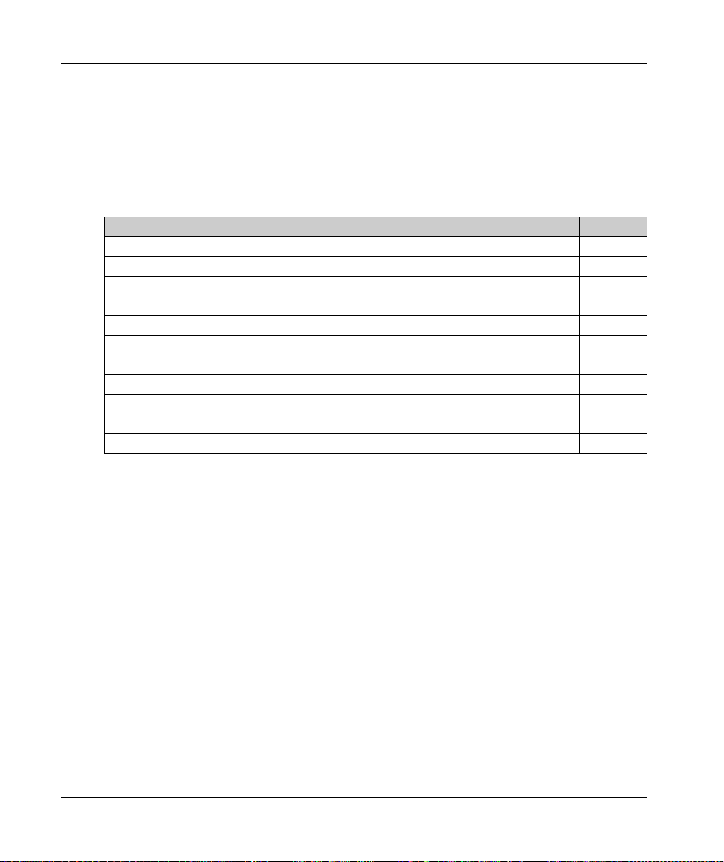
Engineering
Functional Safety
Section 3.4
Functional Safety
What Is in This Section?
This section contains the following topics:
Process Minimizing Risks Associated with the Machine 67
Designated Safety Function 69
Setup, Installation and Maintenance 77
Perform Muting with the Optional Modules DIS1 79
Application Proposals for Hardware-Based Safety Functions 82
Application Proposals for Software-Based Safety Functions 85
Commissioning 86
Best Practices 87
Maintenance 89
Physical Environment 90
Safety Standards 91
Topic Page
66
EIO0000001351 02/2020
Page 67

Process Minimizing Risks Associated with the Machine
General
The goal of designing machines safely is to protect people. The risk associated with machines with
electrically controlled drives comes chiefly from moving machine parts and electricity itself.
Only you, the user, machine builder, or system integrator can be aware of all the conditions and
factors realized in the design of your application for the machine. Therefore, only you can
determine the automation equipment and the related safeties and interlocks which can be properly
used, and validate such usage.
Hazard and Risk Analysis
Based on the system configuration and utilization, a hazard and risk analysis must be carried out
for the system (for example, according to ISO 12100 or ISO 13849-1). The results of this analysis
must be considered when designing the machine, and subsequently applying safety-related
equipment and safety-related functions. The results of your analysis may deviate from any
application examples contained in the present or related documentation. For example, additional
safety components may be required. In principle, the results from the hazard and risk analysis have
priority.
WARNING
NON-CONFORMANCE TO SAFETY FUNCTION REQUIREMENTS
Specify the requirements and/or measures to be implemented in the risk analysis you perform.
Verify that your safety-related application complies to applicable safety regulations and
standards.
Make certain that appropriate procedures and measures (according to applicable sector
standards) have been established to help avoid hazardous situations when operating the
machine.
Use appropriate safety interlocks where personnel and/or equipment hazards exist.
Validate the overall safety-related function and thoroughly test the application.
Failure to follow these instructions can result in death, serious injury, or equipment damage.
Engineering
EIO0000001351 02/2020 67
Page 68

Engineering
The ISO 13849-1 Safety of machinery - Safety-related parts of control systems - Part 1: General
principle for design describes an iterative process for the selection and design of safety-related
parts of controllers to reduce the risk to the machine to a reasonable degree:
To perform risk assessment and risk minimization according to ISO 12100, proceed as follows:
1. Defining the boundary of the machine.
2. Identifying risks associated with the machine.
3. Assessing risks.
4. Evaluating risks.
5. Minimizing risks by:
6. Designing safety-related controller parts (SRP/CS, Safety-Related Parts of the Control System)
To design the safety-related controller parts in an interactive process, proceed as follows:
Step Action
1 Identify necessary safety functions that are executed via SRP/CS (Safety-Related Parts of the
2 Determine required properties for each safety function.
3 Determine the required performance level PL
4 Identify safety-related parts executing the safety function.
5 Determine the performance level PL of the afore-mentioned safety-related parts.
6 Verify the performance level PL for the safety function (PL ≥ PL
7 Verify if all requirements have been met (validation).
Intrinsically safe design
Protective devices
User information (see ISO 12100)
in an interactive process.
Control System).
.
r
).
r
68
Additional information is available on
www.schneider-electric.com
.
EIO0000001351 02/2020
Page 69

Designated Safety Function
Functional Description
With the Inverter Enable function (IE), you can bring drives to a defined safe stop.
This Inverter Enable function relates to the components
Lexium 62 Connection Module
Lexium 62 Distribution Box
Lexium 62 ILM Integrated Servo Drive
In the sense of the relevant standards, the requirements of the stop category 0 (Safe Torque Off,
STO) and stop category 1 (Safe Stop 1, SS1) can be met. Both categories lead to a torque-free
motor while SS1 takes this state after a predefined time. As a result of the hazard and risk analysis,
it may be necessary to choose an additional brake as a safety-related option (for example, for
hanging loads).
With the optionally available Lexium 62 ILM Safety Module it is also possible to realize the
extended safety functions such as Safety Limited Speed (SLS) in connection with the SLC100/200
FS and the associated software EcoStruxure Machine Expert - Safety.
UNINTENDED EQUIPMENT OPERATION
Make certain that no hazards can arise for persons or material during the coast down period
of the axis/machine.
Do not enter the zone of operation during the coast down period.
Ensure that no other persons can access the zone of operation during the coast down period.
Use appropriate safety interlocks where personnel and/or equipment hazards exist.
Failure to follow these instructions can result in death, serious injury, or equipment damage.
Engineering
WARNING
EIO0000001351 02/2020 69
Page 70

Engineering
Designated Safety Function Safe Torque Off (STO)
The Inverter Enable function relates to Lexium 62 Connection Module, Lexium 62 Distribution Box
and Lexium 62 ILM, hereinafter referred to as Lexium 62 Drive System.
The function is selected via a signal (pair) at the input of the Lexium 62 Connection Module (2),
which is forwarded to all drives (7) of the Lexium 62 Connection Module network. The supply
voltage (AC) does not need to be interrupted
The graphic shows the Lexium 62 Drive System with emergency stop:
1 Control cabinet
2 Contactor
3 Lexium 62 Connection Module
4 Emergency stop switch
5 Safety switching device (for example Preventa XPS AV)
6 Lexium 62 ILM Integrated Servo Drive
7 Lexium 62 Distribution Box
8 Logic Motion Controller
Operating Principle
The Inverter Enable function switches off the motor torque. It is sufficient to set a logical zero at the
function input. There is no need to interrupt the power supply. Standstill, however, is not monitored.
Defined Safe State
Inverter Enable is synonymous with "Safe Torque Off (STO)" according to IEC 61800-5-2:2007.
This torque-free state is automatically entered when errors are detected and is therefore the
defined safe state of the drive.
70
EIO0000001351 02/2020
Page 71

Mode of Operation
The safety-related circuit with Inverter Enable was developed to minimize wear on the mains
contactor. When the stop or the emergency stop button is activated, the mains contactor is not
switched off. The defined safe stop is achieved by removing the “InverterEnable” for the optocouple
in the power stage. Thus, the PWM signals cannot control the power stage so that a startup of the
drives is prevented (pulse pattern lock).
You can use the Inverter Enable function to implement the control function “Stopping in case of
emergency” (IEC 60204-1) for stop categories 0 and 1. Use an appropriate external safety-related
circuit to prevent the unintended restart of the drive after a stop, as required in the machine
directive.
Stop Category 0
In stop category 0 (Safe Torque Off, STO), the drive coasts to a stop (provided there are no
external forces operating to the contrary). The STO safety-related function is intended to help
prevent an unintended start-up, not stop a motor, and therefore corresponds to an unassisted stop
in accordance with IEC 60204-1.
In circumstances where external influences are present, the coast down time depends on physical
properties of the components used (such as weight, torque, friction, and so on), and additional
measures such as mechanical brakes may be necessary to help prevent any hazard from
materializing. That is to say, if this means a hazard to your personnel or equipment, you must take
appropriate measures (refer to
Hazard and Risk Analysis (see page 67)
Engineering
).
WARNING
UNINTENDED EQUIPMENT OPERATION
Make certain that no hazards can arise for persons or material during the coast down period
of the axis/machine.
Do not enter the zone of operation during the coast down period.
Ensure that no other persons can access the zone of operation during the coast down period.
Use appropriate safety interlocks where personnel and/or equipment hazards exist.
Failure to follow these instructions can result in death, serious injury, or equipment damage.
EIO0000001351 02/2020 71
Page 72

Engineering
Stop Category 1
For stops of category 1 (Safe Stop 1, SS1) you can request a controlled stop via the Logic Motion
Controller (LMC). The controlled stop by the LMC is not safety-relevant, nor monitored, and does
not perform as defined in the case of a power outage or if an error is detected. The final switch off
in the defined safe state is accomplished by switching off the "Inverter Enable" input. This has to
be implemented by using an external safety-related switching device with safety-related delay (see
Application Proposal (see page 85)
Independent of the safety function, the detectable errors not affecting the safety function are
recognized by the controller, thus avoiding the drive from starting by switching off the mains
contactor. Contactor K2 prevents the mains contactor from being switched on.
Execute Muting
To execute muting, determine the muting reaction time for switching off, that is, without the
Inverter Enable function, within the application.
Should a response time be required because of the risk assessment of the machine, the total
response time of the machine has to be taken into account. That is to say, the components related
to the safety functions from the sensor to the drive shaft or the driven mechanics have to be
considered. The determined reaction time must correspond to the results of the hazard and risk
analysis.
UNINTENDED EQUIPMENT OPERATION
Verify that the maximum response time corresponds to your risk analysis.
Be sure that your risk analysis includes an evaluation for the maximum response time.
Validate the overall function with regard to the maximum response time and thoroughly test
the application.
Failure to follow these instructions can result in death, serious injury, or equipment damage.
).
WARNING
72
Proceed as follows to disable the Inverter Enable function:
Step Action
1 You can deactivate the Inverter Enable function by using the optional module DIS1
2 In order to use the optional module DIS1, you must define the configuration with the parameter
(see page 79)
Result:The defined safe state can only be achieved if the power is removed from the power
supply.
InverterEnableConfig of the Lexium 62 ILM in the motion controller configuration.
.
EIO0000001351 02/2020
Page 73

Engineering
If the software configuration does not match the physical configuration of the Lexium 62 ILM, then
the diagnostic message 8978 InverterEnableConfig invalid with Ext. diagnostic = x(HW)!=y(Cfg) is
triggered. The drive is disabled as long as the configuration is incorrect. The detected error can
only be acknowledged if the set InverterEnableConfig corresponds to the physical
configuration. The deactivation of the Inverter Enable function can be used to divide the drives on
a Lexium 62 Connection Module in two groups if it is technically not possible to use two
Lexium 62 Connection Module for the two groups in the existing machine.
The axes without Inverter Enable function become torque-free via the mains contactor and come
to a stop.
If only some of the drives attached to a Lexium 62 Connection Module are to be put in the defined
safe state, this can be achieved by the configuration of the drives. This can be of interest, for
example, for maintenance procedures. If an optional module DIS1 is set, then the Inverter Enable
signal is ignored.
To implement the emergency stop, the supply voltage on the Lexium 62 Power Supply must be
interrupted:
1 Control cabinet
2 Emergency stop switch
3 Safety switching device (for example Preventa XPS AV)
4 Contactor
5 Switch: Operating mode (normal/maintenance)
6 Lexium 62 Connection Module
7 Lexium 62 ILM Integrated Servo Drive
8 Lexium 62 Distribution Box
9 Logic Motion Controller
EIO0000001351 02/2020 73
Page 74
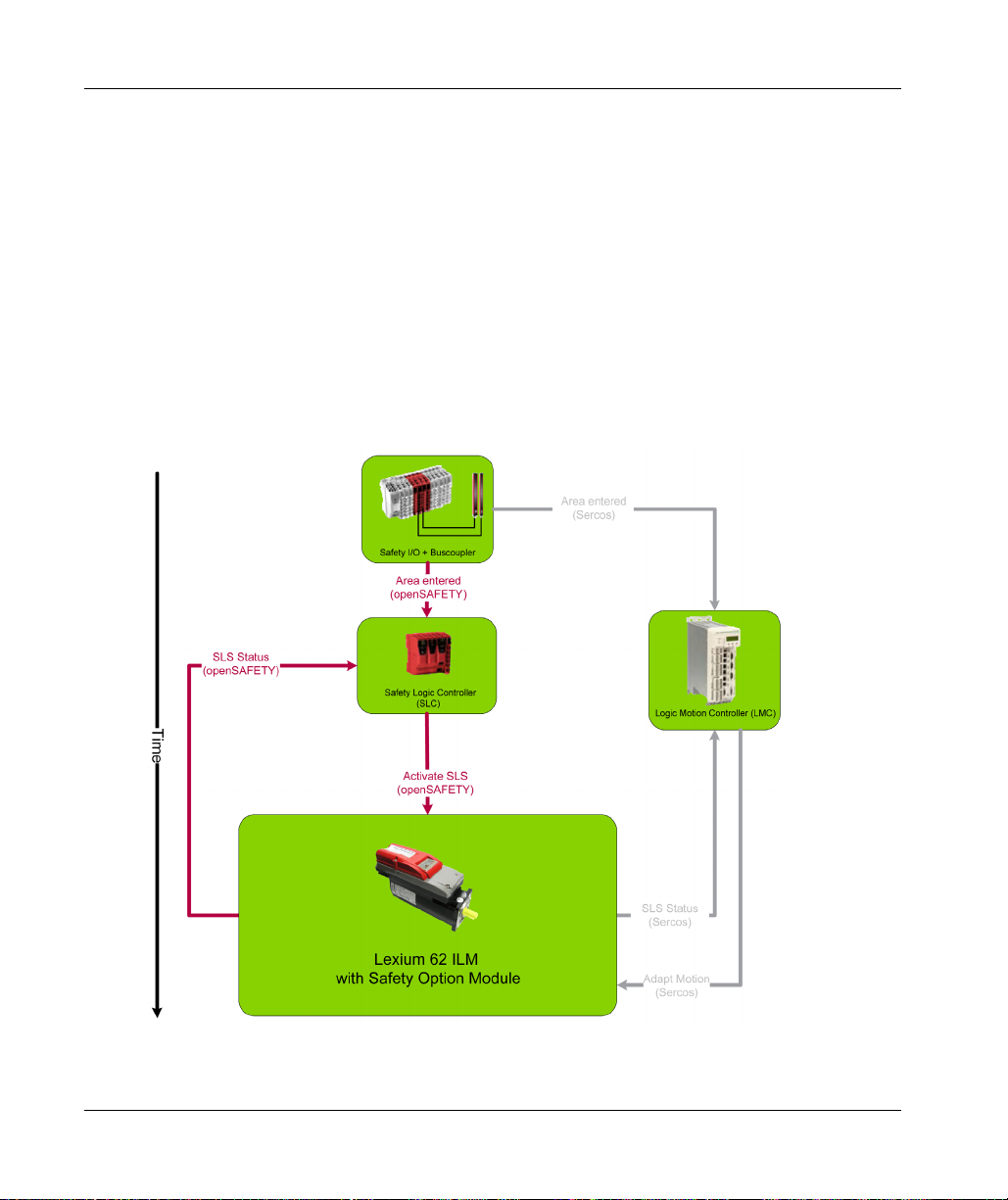
Engineering
Extended Safety-Related Functions - Operating Principle
The safety concept is based upon the general consideration that the required safety-related travel
movement is performed by the controller and the drive. The safety system monitors the correct
execution of the motion, and if it is not respected the safety system initiates the required fall-back
level (for example the defined safe state).
An example for Safe Limited Speed (SLS) is as follows:
A light curtain is connected to a safety-related digital input. As soon as a person enters the
protected zone passing the light curtain, a corresponding information is transmitted to the
Safety Logic Controller (SLC) and the LMC via the Sercos bus. After that the LMC initiates an
adequate travel movement, for example by using decelerating and then moving slowly. After an
adjustable delay time this slow movement is monitored by Lexium 62 ILM Safety Module. Upon
exceeding an adjustable threshold value (for example, high velocity), the required fall-back level is
entered, for example, the defined safe state.
Application of safety-related function SLS:
74
EIO0000001351 02/2020
Page 75

Extended Safety-Related Functions - Inverter Enable via Hardware Input
The Lexium 62 ILM Safety Module has been primarily developed to realize the extended safety
functions, however, it still can be accessed using the usual hardware input for the Inverter Enable
of the Lexium 62 Drive System. If only this is to be used, the device still needs to be configured and
parameterized by using the software. If it is hardwired, the Safe Torque Off (STO) function can be
triggered via this input or the Sercos bus. The Lexium 62 ILM Safety Module can be configured to
ignore the hardware input. In this case, the Safe Torque Off (STO) function can only be activated
upon a request over the Sercos bus. Otherwise, if the hardware input is not ignored then both
requests (hardware input and Sercos bus) are verified and the Safe Torque Off (STO) function is
triggered if one or both requests are active. The default configuration is not to ignore the hardware
input.
Extended Safety-Related Functions - Defined Safe State
The defined safe state of the device is characterized by the following features:
The drive is torque-free, which is equivalent to Safe Torque Off (STO) according to IEC 61800-
5-2.
There is no safety-related communication from the drive via the Sercos bus.
This state is automatically entered when errors are detected.
Validity of the Safety Case
The safety case for the Inverter Enable function of the Lexium 62 ILM is identified and defined by
the standards listed in
Safety Standards (seepage91)
. The safety case for the designated safety
function of the Lexium 62 ILM system applies to the following hardware codes, which can be found
examining the appropriate software object in EcoStruxure Machine Expert
Machine Expert, Programming Guide)
:
Engineering
(see EcoStruxure
Unicode Hardware code
ILM 070/xx xxxxxxxxx1xx, xxxxxxxxx2xx
ILM 100/xx xxxxxxxxx1xx, xxxxxxxxx2xx
ILM140/xx xxxxxxxxx1xx, xxxxxxxxx2xx
DIS1 1
ILM62CM xxxxxx1xx, xxxxxx2xx
ILM62DB xxxxxx1xx
Device Hardware code
VW3E702200000 011A1110
For questions on this, contact your Schneider Electric representative.
EIO0000001351 02/2020 75
Page 76

Engineering
Interface and Control
The Inverter Enable function is operated via the switching thresholds of the InverterEnable-input
(IE_p1/IE_p2 at Pin1/Pin2, IE_n1/IE_n2 at Pin3/Pin4) of the Lexium 62 Connection Module.
Maximum downtime: 500 µs at U
Maximum test pulse ratio: 1 Hz
STO active: -3 V ≤ U
Power stage active: 15 V ≤ U
For information on the technical data and electrical connections, refer to the chapter
Data (see page 185)
> 20 V with dynamic control
IEX
≤ 5 V
IE
≤ 30 V
IE
Technical
.
76
EIO0000001351 02/2020
Page 77

Setup, Installation and Maintenance
Prevent Possible Unintended Operation and Avoid Overvoltage
The following measures avoid overvoltages and help prevent possible unintended equipment
operation through conductive pollution or parts falling into the device:
DANGER
ELECTRIC SHOCK, EXPLOSION, OR ARC FLASH
Install Lexium 62 Connection Module in a control cabinet or housing with a minimum IP 54
rating.
Comply with the clearances and creepage distances according to EN 50178.
Lexium 62 ILM Integrated Servo Drive must only be operated with 24 Vdc power supplies
certified according to EN 60950 or EN 50178.
Failure to follow these instructions will result in death or serious injury.
NOTE: These power supply units do not deliver an overvoltage over 120 Vdc for more than 120 ms
or no permanent overvoltage over 60 Vdc.
Only operate the drive system with approved, specified cables, accessories and replacement
equipment by Schneider Electric.
Engineering
DANGER
ELECTRIC SHOCK OR ARC FLASH
Do not use non-Schneider Electric approved cables, accessories or any type of replacement
equipment.
Failure to follow these instructions will result in death or serious injury.
Avoid Unintentional Restart
The unintentional restart of the equipment must be avoided by appropriate means, depending on
your particular application.
DANGER
UNINTENTIONAL RESTART OF THE MOTOR
Ensure that a restart of the motor is not possible after a return of power or the tripping of a
functional safety device unless preceded by a deliberate enable signal from the system.
Ensure that the enable signal meets the specified safety criteria.
Failure to follow these instructions will result in death or serious injury.
EIO0000001351 02/2020 77
Page 78

Engineering
Encoder Connection When Using Extended Safety-Related Functions
Lexium 62 ILM Safety Module enables the use of extended, position-dependent and/or velocitydependent safety-related functions.
DANGER
INOPERABLE SAFETY FUNCTION
Observe the specified maximum configuration (number of devices, network structure and
cable length), or else a voltage drop of the Inverter Enable signal will occur over the cable
length and therefore the system will be in the defined safe state continuously.
Connect per Lexium 62 Connection Module a maximum of 45 Lexium 62 ILMs.
Failure to follow these instructions will result in death or serious injury.
For more information on the dimensions of the maximum system extension for
structure or tree structure or daisy chain structure (see page 120)
.
Wiring in line
78
EIO0000001351 02/2020
Page 79

Perform Muting with the Optional Modules DIS1
Overview
Implementation of Emergency stops combining hardwired control of supply power with the
Inverter Enable function:
Lexium 62 ILM Maintenance Emergency stop Parameter InverterEnableConfig
Lexium 62 ILM
without DIS1
Lexium 62 ILM with
DIS1
How to Install the Optional Modules DIS1
You cannot use the option modules DIS1 and Lexium 62 ILM Safety Module together.
Step Action
1 Remove power to the Lexium 62 Power Supply during the installation of the optional module
2 Remove the transparent cover plate on the motor.
3 Remove plugged in jumpers J1 and J2:
Torque-free motor Torque-free motor Standard/1
– Torque-free motor Off/0
DIS1.
Engineering
EIO0000001351 02/2020 79
Page 80

Engineering
Step Action
4 Connect the optional module DIS1 by inserting it into the contact pin, as shown in the following
graphic:
5 Replace the transparent cover plate on the motor and secure it.
How to Disassemble the Optional Module DIS1
Step Action
1 Remove power to the Lexium 62 Power Supply during the installation of the optional module
DIS1.
2 Remove the transparent cover plate on the motor.
3 Remove the optional module DIS1.
80
EIO0000001351 02/2020
Page 81

Step Action
4 Reconnect the jumpers J1 and J2.
5 Replace the transparent cover plate on the motor and secure it.
Engineering
EIO0000001351 02/2020 81
Page 82

Engineering
Application Proposals for Hardware-Based Safety Functions
How to Implement the Safe Stop Category 1 (SS1)
Refer to the schematic EL-1122-05-xx: Inverter Enable circuit Lexium 62 Connection Module /
Lexium 62 ILM using the Logic Motion Controller LMC•00C with safety switch device for an
emergency stop circuit.
NOTE:
All application proposals provide for a protected Inverter Enable-wiring (control cabinet IP54)
from the safety-related switch device to the Lexium 62 Connection Module, as wiring issues
need to be ruled out.
Protection against automatic restart must be provided by the external safety-related switch
device.
NOTE: The mains contactor in the circuit suggestion EL-1122-05-xx is not necessary for functional
safety purposes. It is, however, used in the application proposal for the device protection of the
Lexium 62 Power Supply or the components connected to it.
82
EIO0000001351 02/2020
Page 83

EL-1122-05-xx Sheet 1:
Engineering
EIO0000001351 02/2020 83
Page 84

Engineering
EL-1122-05-xx Sheet 2:
84
EIO0000001351 02/2020
Page 85

Application Proposals for Software-Based Safety Functions
How to Use the Inverter Enable via Hardware or Extended Safety Functions
Proceed as follows to use the Inverter Enable via hardware or extended safety functions using the
Lexium 62 ILM Safety Module:
Step Action
1 Perform the assembly for Lexium 62 ILM Safety Module.
2 Configure the safety-related network.
3 Adjust the parameters, in particular the prioritization of Inverter Enable via hardware and STO
via the bus.
4 Program the EcoStruxure Machine Expert - Safety application.
NOTE: Observe the information on the parameters and the EcoStruxure Machine Expert - Safety
in the EcoStruxure Machine Expert online help.
Further information on the parameters and the EcoStruxure Machine Expert - Safety Software can
be found in the EcoStruxure Machine Expert online help.
Engineering
EIO0000001351 02/2020 85
Page 86

Engineering
Commissioning
General
Step Action
1 Carry out a functional test of the STO function for all drives that need the safety function.
2 Especially verify the correct application of the axes without Inverter Enable function.
3 Complete installation in accordance with the EMC regulations and further specifications in the
4 Afterwards, commission the drive systems.
NOTE: When using the extended safety functions, the Lexium 62 ILM Safety Module must be
configured, parameterized, and programmed according to the EcoStruxure Machine Expert online
help and the EcoStruxure Machine Expert - Safety online help.
device operating manuals.
86
EIO0000001351 02/2020
Page 87

Best Practices
General
At machine start-up, the connected drives are usually hidden from sight of the machine operator
and cannot be monitored directly.
UNSUPERVISED MACHINE START-UP
Only start the machine if there are no persons within the zone of operation of moving machine
components.
Failure to follow these instructions can result in death, serious injury, or equipment damage.
Verify Connections
Step Action
1 Verify all terminals, connectors, and other connections on all system components for correct
2 Only use robust connectors and secure fixings.
3 Verify the protective earth ground (24 Vdc PELV (Protective Extra Low Voltage) supply.
4 Verify the wiring of the safety function to the axes to avoid an interchange of the ie_sig and
5 Use coded connectors (refer to chapter
6 Use only appropriate transport packaging to forward or return individual devices.
WARNING
and firm fit.
ie_ref inputs as well as the 24 V supply.
commissioning test (refer to chapter
Information about Wiring (see page 51)
Commissioning (see page 86)
Engineering
) and perform a
).
DANGER
ELECTRIC SHOCK DUE TO INADEQUATE PROTECTIVE SEPARATION
Only connect devices, electrical components, or lines to the signal voltage connectors of these
products that feature a sufficient, protective separation from the connected circuits in accordance
with the standards (IEC 61800-5-1: Adjustable speed electrical power drive systems - safety
requirements).
Failure to follow these instructions will result in death or serious injury.
EIO0000001351 02/2020 87
Page 88

Engineering
External Forces
The defined safe state of the motor is the torque-free output shaft. If external forces act upon the
output shaft, it will not necessarily maintain its position. In any case, the motor will coast to an
unassisted stop. This coast down time depends on physical properties of the components used
(such as weight, torque, friction, and so on), and additional measures such as mechanical brakes
may be necessary to help prevent any hazard from materializing. If the torque-free defined safe
state is inappropriate for your application where external forces may move the output shaft as
determined by your risk assessment, implement other external safety-related measures.
UNINTENDED EQUIPMENT OPERATION
Make certain that no hazards can arise for persons or material during the coast down period
of the axis/machine.
Do not enter the zone of operation during the coast down period.
Ensure that no other persons can access the zone of operation during the coast down period.
Use appropriate safety interlocks where personnel and/or equipment hazards exist.
Failure to follow these instructions can result in death, serious injury, or equipment damage.
Hanging and Pulling Loads
UNINTENDED AXIS MOVEMENT
Do not use the internal holding brake as a safety-related measure.
Only use certified external brakes as safety-related measures.
Failure to follow these instructions can result in death, serious injury, or equipment damage.
WARNING
WARNING
88
If the suspension of hanging / pulling loads is a safety objective for the machine, then you can only
achieve this objective by using an appropriate external brake as a safety-related measure.
NOTE: The drive does not provide its own safety-related output to connect an external brake to
use as a safety-related measure.
EIO0000001351 02/2020
Page 89

Maintenance
General
The Inverter Enable function has been designed for a defined lifetime that does not require to verify
the safety-related function, nor any specific maintenance requirements. After this lifetime
(see page 91)
the aging of the component. If you want to ensure the functional safety after this period, you need
to replace the device that includes the safety function.
NOTE: Subject the product to a complete function test after replacement.
The following applies for Lexium 62 ILM Safety Module.
In addition to the LED state, data of the Safety Logger is also available in the EcoStruxure Machine
Expert Logic Builder. These are provided for information only and must not be used for safetyrelated diagnostics.
For information about initial start-up and maintenance, refer to the chapter
Maintenance (see page 97)
Engineering
has elapsed, a statement about the Inverter Enable function cannot be made due to
Installation and
.
EIO0000001351 02/2020 89
Page 90

Engineering
Physical Environment
General
The system is not protected against physical or chemical sources of damage by any design
features, such as:
toxic,
explosive,
corrosive,
highly reactive, or
inflammable types.
This equipment has been designed to operate outside of any hazardous location. Only install this
equipment in zones known to be free of a hazardous atmosphere.
POTENTIAL FOR EXPLOSION
Install and use this equipment in non-hazardous locations only.
Failure to follow these instructions will result in death or serious injury.
UNINTENDED EQUIPMENT OPERATION
Observe and conform to ambient temperatures, storage temperatures and transport
temperatures of the individual components as specified in the operating manuals of the
components.
Prevent the formation of moisture during the operation, storage and transport of individual
components.
Conform to the vibration and shock requirements specified in the operating manuals for the
components when operating, storing and transporting system components.
Failure to follow these instructions can result in death, serious injury, or equipment damage.
DANGER
WARNING
90
The Lexium 62 Power Supply and the Lexium 62 Connection Module must only be installed in an
electrical equipment enclosure (for example, in a control cabinet). The electrical equipment
enclosure must be lockable by using a key or tool
The Lexium 62 ILM and the Lexium 62 Distribution Box are intended for installation in a machine.
EIO0000001351 02/2020
Page 91

Safety Standards
Overview
The designated safety functions have been designed and tested for functional safety according to
the following standards
IEC 61508:2010
IEC 61800-5-2:2007
EN ISO 13849-1:2008
IEC 62061:2005
An independent assessment was performed by TÜV Nord.
According to the above listed standards, the figures for the devices for using the Inverter Enable
function are as follows:
Engineering
Standard characteristics Lexium 62 Connection
Module
SFF (IEC 61508)
99% 99.9% 99%
Lexium 62 ILM Lexium 62 ILM with installed
Lexium 62 ILM Safety Module
1
Safe failure fraction
HFT (IEC 61508)
111
Hardware Fault Tolerance
Type (IEC 61508) A A B
SIL (IEC 61508)
333
Safety Integrity Level
SILCL (IEC 62061)
Safety Integrity Level
claim limit
PFH (IEC 61508)
-9
1.3*10
/h 0.08*10-9/h 1.6*10-9/h
Probability of Dangerous
Failures per Hour
PL (cat) (EN ISO 13849-1)
e (4) e (4) e(4)
Performance Level
(Category)
MTTFd (EN ISO 13849-1)
881 years 14487 years 320 years
Mean Time to Dangerous
Failure
1
Lexium 62 Distribution Box: The elimination from consideration of certain errors within the safety-related
parts of the control system, known as Fault Exclusion within various IEC, ISO, NFPA and ANSI standards,
has been applied because clearances and creepage standards have been respected in the product. The
plug-in connectors have been included in the PFH figures of Lexium 62 Connection Module and
Lexium 62 ILM.
NOTE: The values specified are rounded individually and are therefore not a result of a conversion by for
example, PFH in MTTFd or the comparative tables from EN ISO 13849-1:2008.
EIO0000001351 02/2020 91
Page 92
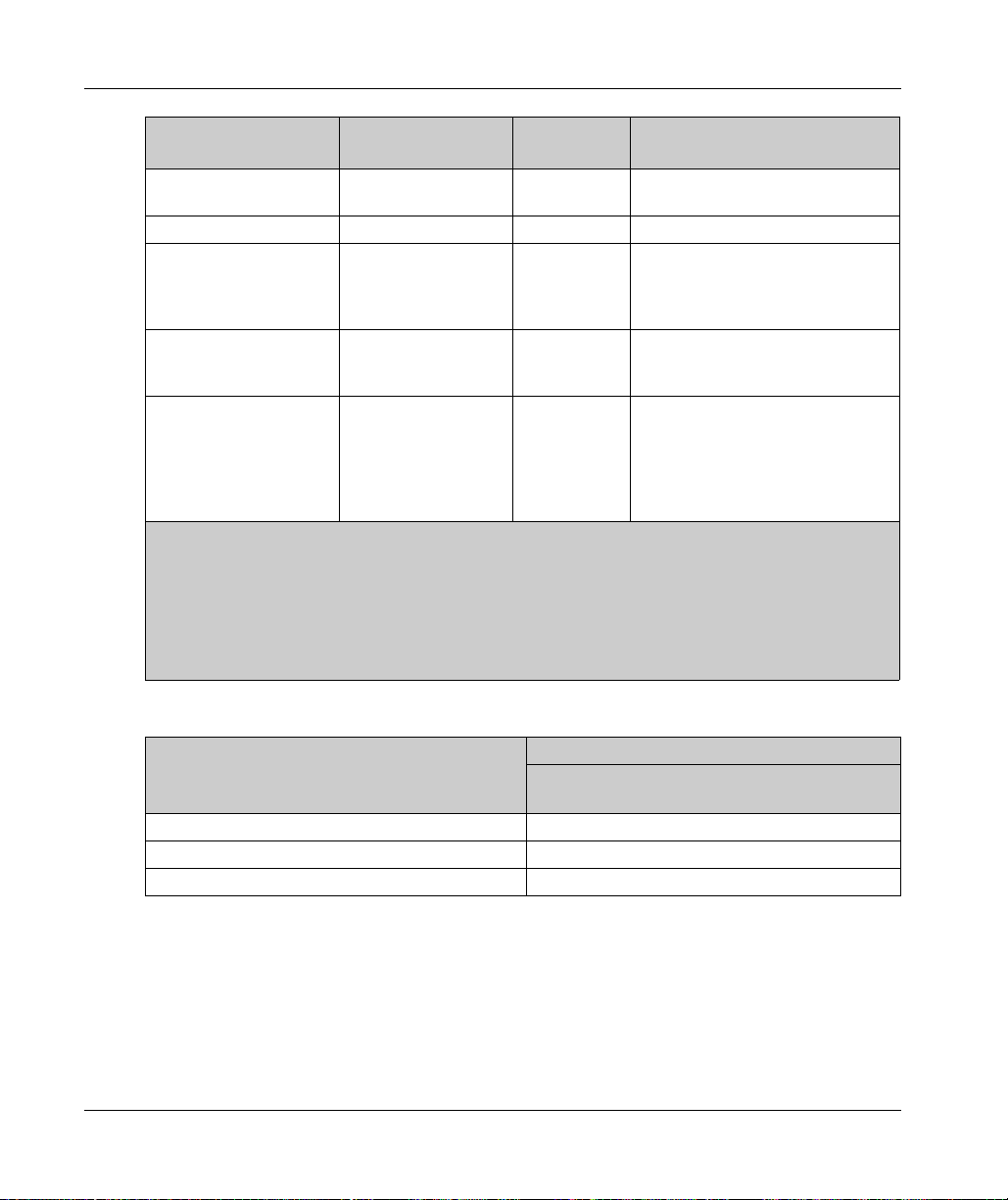
Engineering
Standard characteristics Lexium 62 Connection
Module
DC (EN ISO 13849-1)
99% 99% 99%
Lexium 62 ILM Lexium 62 ILM with installed
Lexium 62 ILM Safety Module
1
Diagnostic Coverage
Lifetime 20 years 20 years 20 years
Maximum reaction time
5 ms 5 ms 10 ms
between the request and
execution of the
designated safety function
Maximum reaction time
5 ms 5 ms 10 ms
before the detection of
safety-related errors
Maximum reaction time
Not applicable Not applicable 10 ms
between exceeding the
threshold values of
extended safety functions
and the initiation of
substitute reactions
1
Lexium 62 Distribution Box: The elimination from consideration of certain errors within the safety-related
parts of the control system, known as Fault Exclusion within various IEC, ISO, NFPA and ANSI standards,
has been applied because clearances and creepage standards have been respected in the product. The
plug-in connectors have been included in the PFH figures of Lexium 62 Connection Module and
Lexium 62 ILM.
NOTE: The values specified are rounded individually and are therefore not a result of a conversion by for
example, PFH in MTTFd or the comparative tables from EN ISO 13849-1:2008.
92
Standard characteristics - Lexium 62 ILM Safety Module
Standard characteristics Lexium 62 ILM Safety Module
MTTFd (EN ISO 13849-1)
Mean Time to Dangerous Failure [years]
Use of SLS (Safely Limited Speed (SLS)) etc. –
... with Sick Stegmann encoder SKM36 250
... with Sick Stegmann encoder SKS36 250
EIO0000001351 02/2020
Page 93

Special Conditions
Section 3.5
Special Conditions
Low Air Pressure
Description
If the installation altitude exceeds the specified rated installation altitude, the performance of the
entire system is reduced.
Low Air Pressure - Lexium 62 Power Supply
Power reduction at increased installation altitude (Lexium 62 Power Supply):
Engineering
EIO0000001351 02/2020 93
Page 94

Engineering
Low Air Pressure - Lexium 62 Connection Module
Power reduction at increased installation altitude (Lexium 62 Connection Module):
94
EIO0000001351 02/2020
Page 95

Low Air Pressure - Lexium 62 ILM
Power reduction at increased installation altitude (Lexium 62 ILM at 8 kHz clock frequency of
power stage):
NOTE: Multiply the values with the nominal current at 40 °C / 104 °F in order to calculate the
maximum current value, depending on the required installation altitude.
Engineering
EIO0000001351 02/2020 95
Page 96

Engineering
96
EIO0000001351 02/2020
Page 97

5
Lexium 62 ILM
Installation and Maintenance
EIO0000001351 02/2020
Installation and Maintenance
Chapter 4
Installation and Maintenance
What Is in This Chapter?
This chapter contains the following sections:
Section Topic Page
4.1 Prerequisites for Installation and Maintenance 98
4.2 Commissioning 99
4.3 Maintenance, Repair, Cleaning, Replacement Equipment Inventory 124
4.4 Replacing Components and Cables 134
EIO0000001351 02/2020 97
Page 98

Installation and Maintenance
Prerequisites for Installation and Maintenance
Section 4.1
Prerequisites for Installation and Maintenance
Prerequisites for Maintenance and Installation
General Information
Proceed with care during the following steps in order to help to avoid the following points:
Injuries and material damage
Incorrect installation and programming of components
Incorrect operation of components
Use of non-authorized cables or modified components
WARNING
INCORRECT INSTALLATION
Ensure a correct installation and maintenance of the system according to this manual.
Failure to follow these instructions can result in death, serious injury, or equipment damage.
The Lexium 62 ILMs (drive/motor combination) have been derived from the Schneider Electric
SH3 family of motors, and therefore share many characteristics. However, when it comes to
mounting the motor, the Lexium 62 ILMs are equivalent to the SH3 motors. Refer to the
Servo motor, User Guide (see SH3 Servo Motor, User Guide)
Lexium 62 ILMs.
The correspondence between the Lexium 62 ILMs and the SH3 motors are as follows:
SH3 -
for details of installing the
98
Lexium 62 ILM SH3 motor
ILM070 SH3070
ILM100 SH3100
ILM140 SH3140
EIO0000001351 02/2020
Page 99

Commissioning
Section 4.2
Commissioning
What Is in This Section?
This section contains the following topics:
Prerequisites for Commissioning 100
Preparing Commissioning 101
Grinding the Holding Brake 103
Preparing the Control Cabinet 104
Mounting 108
Wiring the Lexium 62 Connection Module in Linear or Tree Topologies 114
Wiring from the Lexium 62 Connection Module in a Daisy Chain Topology 120
Installation and Maintenance
Topic Page
EIO0000001351 02/2020 99
Page 100

Installation and Maintenance
Prerequisites for Commissioning
Prerequisites
ELECTRIC SHOCK, EXPLOSION, OR ARC FLASH
Disconnect all power from all equipment including connected devices prior to removing any
covers or doors, or installing or removing any accessories, hardware, cables, or wires.
Place a "Do Not Turn On" or equivalent hazard label on all power switches and lock them in
the non-energized position.
Wait 15 minutes to allow the residual energy of the DC bus capacitors to discharge.
Measure the voltage on the DC bus with a properly rated voltage sensing device and verify
that the voltage is less than 42.4 Vdc.
Do not assume that the DC bus is voltage-free when the DC bus LED is off.
Block the motor shaft to prevent rotation prior to performing any type of work on the drive
system.
Do not create a short-circuit across the DC bus terminals or the DC bus capacitors.
Replace and secure all covers, accessories, hardware, cables, and wires and confirm that a
proper ground connection exists before applying power to the unit.
Use only the specified voltage when operating this equipment and any associated products.
Failure to follow these instructions will result in death or serious injury.
DANGER
100
DANGER
ELECTRIC SHOCK, EXPLOSION, OR ARC FLASH
Operate electrical components only with a connected protective ground (earth) cable.
After the installation, verify the secure connection of the protective ground (earth) cable to all
electrical devices to ensure that connection complies with the connection diagram.
Before enabling the device, safely cover the live components to prevent contact.
Do not touch the electrical connection points of the components when the module is
energized.
Provide protection against indirect contact.
Connect and disconnect cables and terminals only after you have verified that the power has
been removed from the system.
Failure to follow these instructions will result in death or serious injury.
EIO0000001351 02/2020
 Loading...