

Page 1
Energy meters
iEM3100 / iEM3200 / iEM3300 series
User manual
DOCA0005EN-13
03/2022
www.se.com
Page 2

Legal Information
The Schneider Electric brand and any trademarks of Schneider Electric SE and its
subsidiaries referred to in this guide are the property of Schneider Electric SE or its
subsidiaries. All other brands may be trademarks of their respective owners.
This guide and its content are protected under applicable copyright laws and
furnished for informational use only. No part of this guide may be reproduced or
transmitted in any form or by any means (electronic, mechanical, photocopying,
recording, or otherwise), for any purpose, without the prior written permission of
Schneider Electric.
Schneider Electric does not grant any right or license for commercial use of the guide
or its content, except for a non-exclusive and personal license to consult it on an "as
is" basis. Schneider Electric products and equipment should be installed, operated,
serviced, and maintained only by qualified personnel.
As standards, specifications, and designs change from time to time, information
contained in this guide may be subject to change without notice.
To the extent permitted by applicable law, no responsibility or liability is assumed by
Schneider Electric and its subsidiaries for any errors or omissions in the informational
content of this material or consequences arising out of or resulting from the use of the
information contained herein.
Page 3
Safety information
Important information
Read these instructions carefully and look at the equipment to become familiar
with the device before trying to install, operate, service, or maintain it. The
following special messages may appear throughout this manual or on the
equipment to warn of potential hazards or to call attention to information that
clarifies or simplifies a procedure.
The addition of either symbol to a “Danger” or “Warning” safety label indicates
that an electrical hazard exists which will result in personal injury if the
instructions are not followed.
This is the safety alert symbol. It is used to alert you to potential personal injury
hazards. Obey all safety messages that accompany this symbol to avoid possible
injury or death.
iEM3100 / iEM3200 / iEM3300 series
DANGER
DANGER indicates a hazardous situation which, if not avoided, will result in
death or serious injury.
Failure to follow these instructions will result in death or serious injury.
WARNING
WARNING indicates a hazardous situation which, if not avoided, could result
in death or serious injury.
CAUTION
CAUTION indicates a hazardous situation which, if not avoided, could result in
minor or moderate injury.
NOTICE
NOTICE is used to address practices not related to physical injury.
Please note
Electrical equipment should be installed, operated, serviced and maintained only
by qualified personnel. No responsibility is assumed by Schneider Electric for any
consequences arising out of the use of this material. A qualified person is one who
has skills and knowledge related to the construction, installation, and operation of
electrical equipment and has received safety training to recognize and avoid the
hazards involved.
DOCA0005EN-13 3
Page 4

iEM3100 / iEM3200 / iEM3300 series
Notices
FCC
This equipment has been tested and found to comply with the limits for a Class B
digital device, pursuant to part 15 of the FCC rules. These limits are designed to
provide reasonable protection against harmful interference in a residential
installation. This equipment generates, uses, and can radiate radio frequency
energy and, if not installed and used in accordance with the instructions, may
cause harmful interference to radio communications. However, there is no
guarantee that the interference will not occur in a particular installation. If this
equipment does cause harmful interference to radio or television reception, which
can be determined by turning the equipment off and on, the user is encouraged to
try to correct the interference by one or more of the following measures:
The user is cautioned that any changes or modifications not expressly approved
by Schneider Electric could void the user’s authority to operate the equipment.
• Reorient or relocate the receiving antenna.
• Increase the separation between the equipment and receiver.
• Connect the equipment to an outlet on a circuit different from that to which the
receiver is connected.
• Consult the dealer or an experienced radio/TV technician for help.
This digital apparatus complies with CAN ICES-3 (B) /NMB-3(B).
4 DOCA0005EN-13
Page 5

About this manual
This manual discusses features of the iEM3100 / iEM3200 / iEM3300 series
energy meters and is intended for use by designers, system builders and
maintenance technicians with an understanding of electrical distribution systems
and monitoring devices.
Document scope
Throughout the manual, the term “meter / device” refers to all models of the
iEM3100 / iEM3200 / iEM3300 series. All differences between the models, such
as a feature specific to one model, are indicated with the appropriate model
number or description.
This manual does not provide configuration information for advanced features
where an expert user would perform advanced configuration. It also does not
include instructions on how to incorporate meter data or perform meter
configuration using energy management systems or software, other than ION
Setup. ION Setup is a free configuration tool available for download from
www.se.com.
Please contact your local Schneider Electric representative to learn what
additional training opportunities are available regarding the iEM3100 / iEM3200 /
iEM3300 series energy meters.
iEM3100 / iEM3200 / iEM3300 series
Validity note
The meters are used to measure the amount of active energy consumed by an
installation or a part of an installation.
This function meets the requirements for:
• Consumption monitoring
• Evaluation of energy items (cost, accounting, etc.)
This function may also satisfy the power-saving incentives implemented by many
countries.
Related documents
Document Number
iEM3100 / iEM3150 installation sheet NHA15785 /
NHA20207
iEM3110 / iEM3115 / iEM3135 / iEM3155 / iEM3165 / iEM3175 installation sheet NHA15789 /
NHA20208
iEM3200 / iEM3250 installation sheet NHA15795 /
NHA20211
iEM3210 / iEM3215 / iEM3235 / iEM3255 / iEM3265 / iEM3275 installation sheet NHA15801 /
NHA20213
iEM3300 / iEM3350 installation sheet HRB91204 /
HRB91205
iEM3310 / iEM3335 / iEM3355 / iEM3365 / iEM3375 installation sheet HRB91202 /
HRB91203
You can download these technical publications and other technical information
from www.se.com.
DOCA0005EN-13 5
Page 6

Page 7

Table of Contents
Safety precautions .................................................................................... 11
Meter overview ..........................................................................................12
Overview of meter functions ...................................................................... 12
Main characteristics..................................................................................12
Functions.................................................................................................14
Hardware and installation ........................................................................16
Overview ................................................................................................. 16
Safety precautions....................................................................................16
Meter sealing points..................................................................................16
Input, output and communications wiring considerations..............................16
Dismounting the meter from a DIN rail........................................................ 17
Considerations for iEM3100 series and iEM3300 series devices
associated with a contactor .......................................................................17
iEM3100 / iEM3200 / iEM3300 series
iEM3100 series: 63 A meters ...............................................................12
iEM3300 series: 125 A meters .............................................................13
iEM3200 series: 1 A / 5 A meters.......................................................... 13
iEM3100 and iEM3300 series .............................................................. 14
iEM3200 series...................................................................................14
Typical applications.............................................................................14
Front panel display and meter setup......................................................18
Overview ................................................................................................. 18
Data display .............................................................................................18
Data display screen overview...............................................................18
Example: navigating the display screens ..............................................18
Data display screens........................................................................... 19
Resets.....................................................................................................20
Resetting accumulated energy using the display ...................................20
Multi Tariff feature .....................................................................................21
Meter status information............................................................................21
Meter information ..................................................................................... 22
The device clock.......................................................................................22
Date/time format .................................................................................22
Setting the clock initially ......................................................................22
Device configuration .................................................................................23
Entering configuration mode ................................................................23
The front panel display in configuration mode........................................23
Com. Protection setting .......................................................................24
Modifying parameters ...............................................................................24
Selecting a value from a list .................................................................24
Modifying a numerical value.................................................................24
Cancelling an entry ............................................................................. 25
Configuration mode menus ....................................................................... 25
Configuration menu for iEM3100 / iEM3110 / iEM3115 / iEM3300 /
iEM3310 ............................................................................................26
Configuration menu for iEM3150 / iEM3350 ..........................................27
Configuration menu for iEM3135 / iEM3155 / iEM3165 / iEM3175 /
iEM3335 / iEM3355 / iEM3365 / iEM3375 .............................................29
DOCA0005EN-13 7
Page 8

iEM3100 / iEM3200 / iEM3300 series
Communications via Modbus.................................................................. 38
Configuration menu for iEM3200 / iEM3210 / iEM3215 ..........................31
Configuration menu for iEM3250..........................................................33
Configuration menu for iEM3235 / iEM3255 / iEM3265 /
iEM3275 ............................................................................................35
Modbus communication overview ..............................................................38
Modbus communications settings ..............................................................38
Communications LED indicator for Modbus devices ....................................38
Modbus functions .....................................................................................38
Function list........................................................................................38
Table format .......................................................................................39
Command interface ..................................................................................40
Command interface overview...............................................................40
Command request ..............................................................................40
Command list .....................................................................................41
Modbus register list...................................................................................45
System ..............................................................................................45
Meter Setup and Status....................................................................... 45
Energy Pulse Output Setup (iEM3155 / iEM3255 / iEM3355)..................46
Command Interface ............................................................................46
Communication .................................................................................. 46
Input Metering Setup (iEM3155 / iEM3255 / iEM3355) ...........................47
Digital Input (iEM3155 / iEM3255 / iEM3355) ........................................ 47
Digital Output (iEM3155 / iEM3255 / iEM3355)......................................47
PF firmware updates (iEM3155 / iEM3255 / iEM3355) ...........................48
1PH4W Multi LN updates (iEM3155 / iEM3255 / iEM3355).....................48
Meter Data ......................................................................................... 49
Overload Alarm (iEM3155 / iEM3255 / iEM3355)...................................51
Read Device Identification......................................................................... 52
Communications via LonWorks ..............................................................53
LonWorks communications overview ......................................................... 53
LonWorks communication implementation..................................................53
External interface file (XIF) ..................................................................53
The LonMaker plug-ins........................................................................53
LED indicators for LonWorks meters ....................................................53
Location of the service pin and Neuron ID............................................. 53
Standard network variable types and configuration properties for reading
data.........................................................................................................54
General variables................................................................................54
System variables ................................................................................ 54
Energy and energy by tariff measurements ...........................................55
Instantaneous (RMS) measurements ................................................... 56
Meter status information ......................................................................56
Resets ...............................................................................................58
Meter configuration properties ................................................................... 58
Date/time setup ..................................................................................58
Basic setup ........................................................................................59
Digital input setup ...............................................................................59
Input metering setup ........................................................................... 59
Overload alarm setup.......................................................................... 60
Multi Tariff setup..................................................................................60
8 DOCA0005EN-13
Page 9

iEM3100 / iEM3200 / iEM3300 series
Network propagation rate setup ...........................................................60
Echelon LonMaker plug-in for data display and meter configuration.............. 61
Installing and registering the LonMaker plug-in......................................61
Browsing the meter using the LonMaker plug-in ....................................62
LonMaker plug-in interface ..................................................................63
Communications via M-Bus.....................................................................64
M-Bus communications overview...............................................................64
Configuring basic communications settings...........................................64
Key terms...........................................................................................64
M-Bus protocol support ............................................................................. 65
M-Bus protocol implementation..................................................................65
M-Bus tool for viewing data and configuring the meter ...........................65
Communications LED indicator for M-Bus meters..................................65
Variable data structure telegram information ...............................................65
Fixed data header...............................................................................65
Decoding secondary address and M-Bus serial number......................... 66
Data record header information............................................................66
Telegram information for data records ........................................................69
Meter information................................................................................ 69
Energy and energy by tariff measurements (INT64 and
FLOAT32) ..........................................................................................69
Instantaneous measurements..............................................................70
Meter status information ......................................................................71
Telegram decode information (all values are in hexadecimal) ................. 73
Telegram information for meter configuration ..............................................84
Supported VIFE codes for meter configuration ...................................... 85
Date/time setup ..................................................................................85
Power system setup............................................................................ 85
Multi Tariff setup..................................................................................85
Communications setup........................................................................ 86
Digital input setup ...............................................................................86
Digital output setup ............................................................................. 86
Overload alarm setup and acknowledgment..........................................87
Resets ...............................................................................................87
M-Bus tool for data display and meter configuration.....................................87
Installing the M-Bus tool ......................................................................88
Accessing the meter using the tool .......................................................88
Viewing meter data using the M-Bus tool ..............................................89
Configuring the meter using the M-Bus tool...........................................90
Communications via BACnet ..................................................................92
BACnet communications overview.............................................................92
BACnet protocol support ........................................................................... 92
BACnet communications implementation ...................................................93
Configuring basic communication parameters .......................................93
Communications LED indicator for BACnet meters................................94
Change of Value (COV) subscriptions...................................................94
BACnet object and property information .....................................................94
Device object......................................................................................94
Analog Input objects............................................................................95
Analog value object............................................................................. 98
Binary input objects............................................................................. 99
DOCA0005EN-13 9
Page 10

iEM3100 / iEM3200 / iEM3300 series
Power, energy and power factor........................................................... 100
Troubleshooting ...................................................................................... 105
Specifications .......................................................................................... 107
Power (PQS).......................................................................................... 100
Power and the PQ coordinate system................................................. 100
Power flow .......................................................................................100
Energy delivered (imported) / energy received (exported) ..........................100
Power factor (PF) ................................................................................... 101
PF lead / lag convention ....................................................................101
PF sign convention ........................................................................... 102
Power factor register format ....................................................................103
Overview ............................................................................................... 105
Diagnosis screen.................................................................................... 105
Diagnostic codes ....................................................................................105
Electrical characteristics.......................................................................... 107
Power system inputs: iEM3100 series ................................................ 107
Power system inputs: iEM3300 series ................................................ 107
Power system inputs: iEM3200 series ................................................ 108
Inputs and outputs ............................................................................ 108
Mechanical characteristics ......................................................................109
Environmental characteristics.................................................................. 109
Measurement accuracy........................................................................... 110
MID ....................................................................................................... 110
Internal clock.......................................................................................... 111
Modbus communications......................................................................... 111
LonWorks communications ..................................................................... 111
M-Bus communications........................................................................... 111
BACnet communications......................................................................... 112
China Standard Compliance ................................................................. 113
10 DOCA0005EN-13
Page 11
Safety precautions iEM3100 / iEM3200 / iEM3300 series
Safety precautions
Installation, wiring, testing and service must be performed in accordance with all
local and national electrical codes.
DANGER
HAZARD OF ELECTRIC SHOCK, EXPLOSION, OR ARC FLASH
• Apply appropriate Personal Protective Equipment (PPE) and follow safe
electrical work practices. See NFPA 70E, CSA Z462 or other local
standards.
• Turn off all power supplying this device and the equipment in which it is
installed before working on or in the equipment.
• Always use a properly rated voltage sensing device to confirm that all power
is off.
• Assume communications and I/O wiring are hazardous live until determined
otherwise.
• Do not exceed the maximum ratings of this device.
• Do not short secondary terminals of Voltage Transformer (VT).
• Do not open secondary terminals of Current Transformer (CT).
• Ground secondary circuit of CTs.
• Do not use the data from the meter to confirm power is off.
• Replace all devices, doors and covers before turning on power to this
equipment.
Failure to follow these instructions will result in death or serious injury.
NOTE: See IEC 60950-1:2005, Annex W for more information on
communications and I/O wiring connected to multiple devices.
WARNING
UNINTENDED OPERATION
Do not use this device for critical control or protection of persons, animals,
property or equipment.
Failure to follow these instructions can result in death, serious injury, or
equipment damage.
WARNING
INACCURATE DATA RESULTS
• Do not rely solely on data displayed on the display or in software to
determine if this device is functioning correctly or complying with all
applicable standards.
• Do not use data displayed on the display or in software as a substitute for
proper workplace practices or equipment maintenance.
Failure to follow these instructions can result in death, serious injury, or
equipment damage.
DOCA0005EN-13 11
Page 12

iEM3100 / iEM3200 / iEM3300 series Meter overview
Meter overview
Overview of meter functions
The meters provide the essential measurement capabilities (for example, current,
voltage, and energy) required to monitor a 1-phase or 3-phase electrical
installation.
The key features of the meters are:
• Measurement of active and reactive energy
• Multi Tariffs (up to 4) controlled by internal clock, digital inputs or
communication
• MID compliance for many of the meters
• Pulse outputs
• Display (current, voltage, and energy measurements)
• Communications via Modbus, LonWorks, M-Bus or BACnet protocols
Main characteristics
iEM3100 series: 63 A meters
Function
Direct measurement (up to 63 A)
Active Energy measurement accuracy class (total and partial
kWh)
Four Quadrant Energy measurements
Electrical measurements (I, V, P, ...)
Controlled by internal clock
Multi Tariff
Measurement display (number of lines)
Digital inputs
Digital outputs
Controlled by digital input(s)
Controlled by communications
Programmable (status, tariff control, or
input monitoring)
Tariff control only
Programmable (energy pulsing or overload
alarm)
Pulse output only
iEM3110
iEM3100
√ √ √ √ √ √ √ √
1 1 1 1 1 1 1 1
— — —
— — —
— —
— —
— — —
3 3 3 3 3 3 3 3
— — —
— —
— — —
—
1
iEM3115
4 4
4 2
2
— — — — — —
iEM3135
iEM3150
iEM3155
iEM3165
—
√
√ √ √ √ √
4
1
— — — — —
1
—
—
—
—
—
√ √ √
4 4 4
2 2 2
4 4 4
1 1 1
1 1
iEM3175
—
Overload alarm
Modbus
LonWorks
Communications
M-Bus
BACnet
MID compliant
Width (18 mm module in DIN rail mounting)
— — —
— — — —
— — — — — — —
— — —
— — — — — —
—
√ √ √
5 5 5 5 5 5 5 5
—
√
√
√ √ √
√ √
— — — —
—
√ √ √
— —
√
√
—
12 DOCA0005EN-13
Page 13

Meter overview iEM3100 / iEM3200 / iEM3300 series
iEM3300 series: 125 A meters
Function
Direct measurement (up to 125 A)
Active Energy measurement accuracy class (total and partial kWh)
Four Quadrant Energy measurements
Electrical measurements (I, V, P, ...)
Controlled by internal clock
Multi Tariff
Measurement display (number of lines)
Digital inputs (programmable for status, tariff control, or input
monitoring)
Digital outputs
Overload alarm
Communications
MID compliant
Width (18 mm module in DIN rail mounting)
Controlled by digital input(s)
Controlled by communications
Programmable (energy pulsing or overload
alarm)
Pulse output only
Modbus
LonWorks
M-Bus
BACnet
iEM3300
√ √ √ √ √ √ √
1 1 1 1 1 1 1
— —
— —
— —
— —
— —
3 3 3 3 3 3 3
— —
— —
—
— —
— — —
— — — — — —
— —
— — — — —
—
7 7 7 7 7 7 7
iEM3310
1
√ √
iEM3335
√
√ √ √ √ √
4
2
4
1
1
— — — — —
√
√
iEM3350
—
—
—
—
—
—
—
√ √
— — — —
—
iEM3355
√ √ √
4 4 4
2 2 2
4 4 4
1 1 1
1 1
√ √ √
√ √ √
iEM3365
— —
√
iEM3375
—
√
—
iEM3200 series: 1 A / 5 A meters
Function
Measurement inputs through CTs (1 A, 5 A)
Measurement inputs through VTs
1 A: Active Energy measurement accuracy class (total and partial
kWh)
5 A: Active Energy measurement accuracy class (total and partial
kWh)
Four Quadrant Energy measurements
Electrical measurements (I, V, P, ...)
Controlled by internal clock
Multi Tariff
Measurement display (number of lines)
Digital inputs
Digital outputs
Controlled by digital input(s)
Controlled by communications
Programmable (status, tariff control, or
input monitoring)
Tariff control only
Programmable (energy pulsing or overload
alarm)
iEM3200
iEM3210
iEM3215
√ √ √ √ √ √ √ √
— — —
1 1 1 1 1 1 1 1
0.5S 0.5S 0.5S 0.5S 0.5S 0.5S 0.5S 0.5S
— — —
— — —
— —
— —
— — —
3 3 3 3 3 3 3 3
— — —
— —
— — —
4 4
4 2
2
iEM3235
iEM3250
iEM3255
iEM3265
√ √ √ √ √
—
√
√ √ √ √ √
4
1
— — — — —
1
—
—
—
—
—
√ √ √
4 4 4
2 2 2
4 4 4
1 1 1
1 1
—
iEM3275
DOCA0005EN-13 13
Page 14

iEM3100 / iEM3200 / iEM3300 series Meter overview
Function
iEM3200
iEM3210
Pulse output only
iEM3215
—
— — — — — —
1
iEM3235
iEM3250
iEM3255
iEM3265
iEM3275
Overload alarm
Modbus
LonWorks
Communications
M-Bus
BACnet
MID compliant
Width (18 mm module in DIN rail mounting)
Functions
These meters can monitor energy consumption by usage, by zone or by feeder in
the cabinet. They can be used to monitor feeders in a main switchboard or to
monitor the main in a distribution cabinet.
iEM3100 and iEM3300 series
Functions
Can directly measure feeders up to:
iEM3100 series: 63 A
iEM3300 series: 125 A
Embedded current transformers (CTs)
— — —
— — — —
— — — — — — —
— — —
— — — — — —
—
√ √ √
5 5 5 5 5 5 5 5
Advantages
Saves installation time and space in the cabinet
No wiring to manage
Clear distribution network
—
√
√
√ √ √
√ √
— — — —
—
√ √ √
— —
√
√
—
Adapted to be installed with Acti9 iC60 (iEM3100 series) or Acti9
C120, NG125 (iEM3300 series) circuit breakers
Can be used for single-phase multi-circuit monitoring 3 single feeders can be monitored with a single meter
Can be used in three-phase systems with or without neutral
iEM3200 series
Functions Advantages
CT and VT connection
Flexible configuration Can be adapted to any distribution network with or without neutral
Can be used in low or medium voltage applications
Typical applications
The following table presents some of the functions of the different meters, the
advantages and main applications.
Functions Advantages Applications Meter
Total and partial energy
counters
Internal clock
Pulse output with a configurable
pulse weight of up to 1 pulse per
1 Wh
Energy usage monitoring
Saves the date and time of last
reset
Collect pulses from the meter
with a Smartlink system, PLC or
any basic acquisition system
Sub-billing management
Metering applications
Provides the timestamp of the
last reset of the partial energy
accumulation
Remote monitoring of energy
consumption
Integrate the meter in to a
system monitoring of a large
number of devices
iEM3100 / iEM3200 / iEM3300
series
All (except iEM3100 / iEM3200 /
iEM3300)
iEM3110 / iEM3210 / iEM3310
14 DOCA0005EN-13
Page 15

Meter overview iEM3100 / iEM3200 / iEM3300 series
Functions Advantages Applications Meter
Manages up to four tariffs,
controlled by the digital input(s),
internal clock or
communications (depending on
meter model)
Measures essential electrical
parameters like current,
average voltage and total power
M-Bus communications
Modbus communications
BACnet communications
LonWorks communications
Four quadrant calculation
Categorize energy consumption
into On Peak and Off Peak,
working days and weekends, or
by different electricity sources
(for example, from the utility and
an electrical generator)
Instantaneous measurements
help you monitor the imbalance
between phases
Total power allows you to
monitor the feeder load level
Communicate advanced
parameters using M-Bus
protocol
Communicate advanced
parameters using Modbus
protocol
Communicate advanced
parameters using BACnet MS/
TP protocol
Communicate advanced
parameters using LonWorks
communications
Identification of imported and
exported active and reactive
energy allows you to monitor
energy flow in both directions:
delivered from the utility and
produced on-site
Energy demand management
Sub-billing management
Identification of local energy
consumption behavior by zone,
by usage or by feeder
Monitoring of feeders or any
sub-cabinet
M-Bus network integration
Modbus network integration
BACnet network integration
LonWorks network integration
Ideal for facilities with back-up
generators or green power
capabilities (for example, solar
panels or wind turbines)
iEM3115 / iEM3135 / iEM3155 /
iEM3165 / iEM3175 / iEM3215 /
iEM3235 / iEM3255 / iEM3265 /
iEM3275 / iEM3335 / iEM3355 /
iEM3365 / iEM3375
iEM3135 / iEM3155 / iEM3165 /
iEM3175 / iEM3235 / iEM3255 /
iEM3265 / iEM3275 / iEM3335 /
iEM3355 / iEM3365 / iEM3375
iEM3135 / iEM3235 / iEM3335
iEM3150 / iEM3155 / iEM3250 /
iEM3255 / iEM3350 / iEM3355
iEM3165 / iEM3265 / iEM3365
iEM3175 / iEM3275 / iEM3375
Measurement of active and
reactive energy
Programmable digital input
Programmable digital output
Allows you to monitor energy
consumption and production
Can be programmed to:
• Count pulses from other
meters (gas, water, etc.)
• Monitor an external status
• Reset the partial energy
accumulation and start a
new period of
accumulation
Can be programmed to:
• Be an active energy (kWh)
pulse output, with a
configurable pulse weight
• Alarm on a power
overload at a configurable
pickup setpoint
Manage energy consumption
and make informed investment
to reduce your energy bill or
penalties (for example, installing
capacitor banks)
This allows for monitoring of:
• WAGES
• Intrusion (for example,
doors opening) or
equipment status
• Energy usage
This allows you to:
• Collect pulses from the
meter with a Smartlink
system, PLC or any basic
acquisition system
• Monitor power levels at a
detailed level and to help
detect an overload before
the circuit breaker trips
iEM3135 / iEM3155 / iEM3165 /
iEM3175 / iEM3235 / iEM3255 /
iEM3265 / iEM3275 / iEM3335 /
iEM3355 / iEM3365 / iEM3375
iEM3135 / iEM3155 / iEM3165 /
iEM3235 / iEM3255 / iEM3265 /
iEM3335 / iEM3355 / iEM3365
DOCA0005EN-13 15
Page 16

iEM3100 / iEM3200 / iEM3300 series Hardware and installation
Hardware and installation
Overview
This section provides supplemental information to help mount and install your
meter. It is intended to be used in conjunction with the installation sheet that ships
in the box with your meter. See your device’s installation sheet for information
related to installation, such as dimensions, mounting and wiring instructions.
Safety precautions
Installation, wiring, testing and service must be performed in accordance with all
local and national electrical codes.
DANGER
HAZARD OF ELECTRIC SHOCK, EXPLOSION, OR ARC FLASH
• Apply appropriate Personal Protective Equipment (PPE) and follow safe
electrical work practices. See NFPA 70E, CSA Z462 or other local
standards.
• Turn off all power supplying this device and the equipment in which it is
installed before working on or in the equipment.
• Always use a properly rated voltage sensing device to confirm that all power
is off.
• Replace all devices, doors and covers before turning on power to this
equipment.
• Do not exceed the maximum ratings of this device.
• Do not touch the current terminal when the meter is energized.
Failure to follow these instructions will result in death or serious injury.
Meter sealing points
All meters have sealing covers and sealing points to help prevent access to inputs
and outputs and current and voltage connections.
Input, output and communications wiring considerations
The pulse output is compatible with S0 format, and the programmable digital
output is compatible with S0 format when configured as a pulse output.
The digital input and output are electrically independent.
The digital output is polarity-independent.
16 DOCA0005EN-13
Page 17
Hardware and installation iEM3100 / iEM3200 / iEM3300 series
iEM
iEM
LL
Load Load
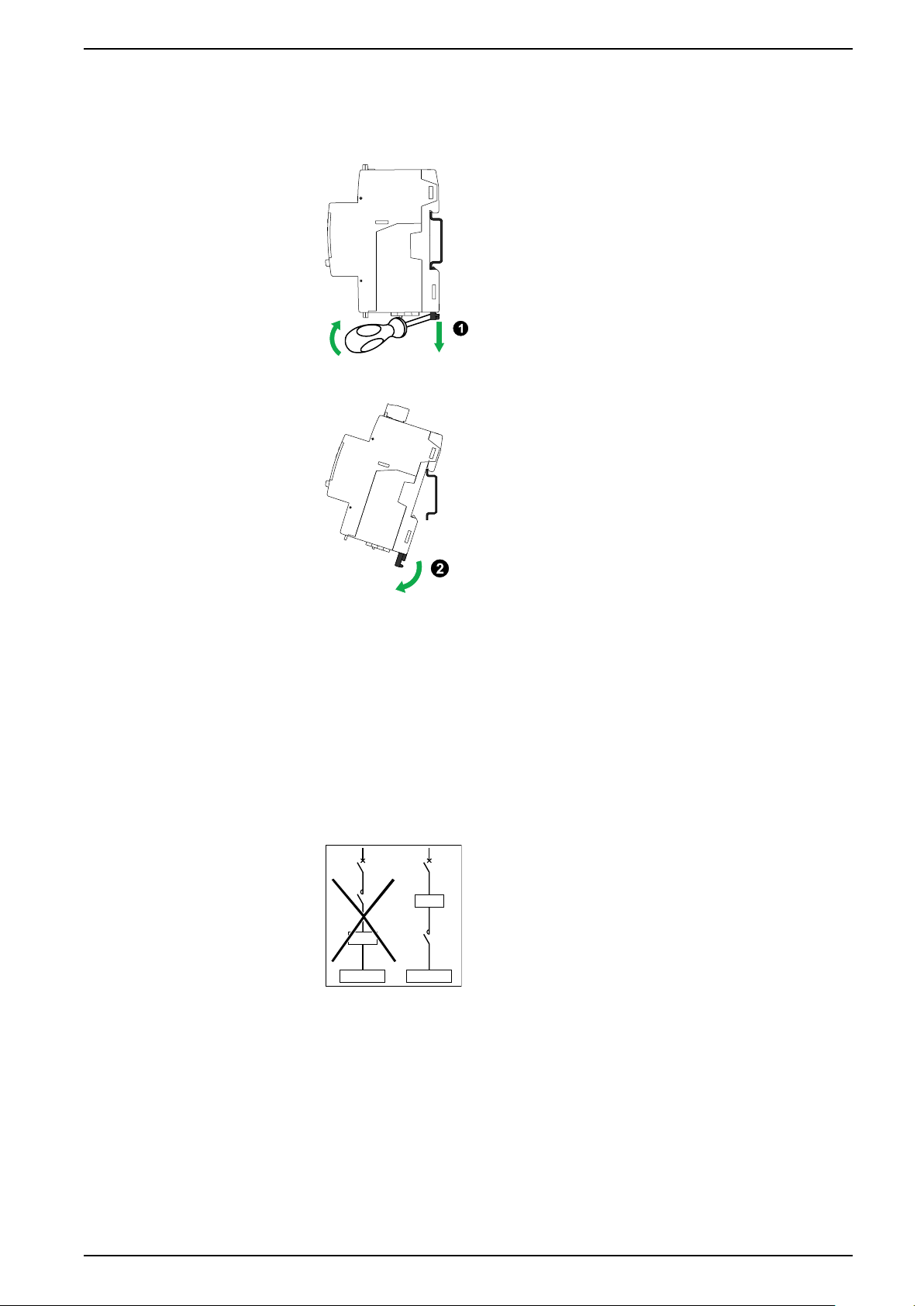
Dismounting the meter from a DIN rail
1. Use a flat-tip screwdriver (≤ 6.5 mm / 0.25 in) to lower the locking mechanism
and release the meter.
2. Lift the meter out and up to free it from the DIN rail.
Considerations for iEM3100 series and iEM3300 series devices associated with a contactor
Connection requirements for iEM3100 / iEM3110 / iEM3115 / iEM3135 / iEM3150 /
iEM3155 / iEM3165 / iEM3175 / iEM3300 / iEM3310 / iEM3335 / iEM3350 /
iEM3355 / iEM3365 / iEM3375:
• When the meter is associated with a contactor, connect the meter upstream
of the contactor.
• The meter must be protected by a circuit breaker.
DOCA0005EN-13 17
Page 18
iEM3100 / iEM3200 / iEM3300 series Front panel display and meter setup
V & I
Partial Reactive E
Tariffs
T1
T2
T3
T4
OK
OK
OK
Front panel display and meter setup
Overview
The meter features a front panel with signaling LEDs, a graphical display, and
menu buttons that allow you to access the information required to operate the
meter and modify parameter settings.
The front panel also allows you to display, configure and reset parameters.
Some meters have the Multi Tariff feature, which allows you to configure different
tariffs.
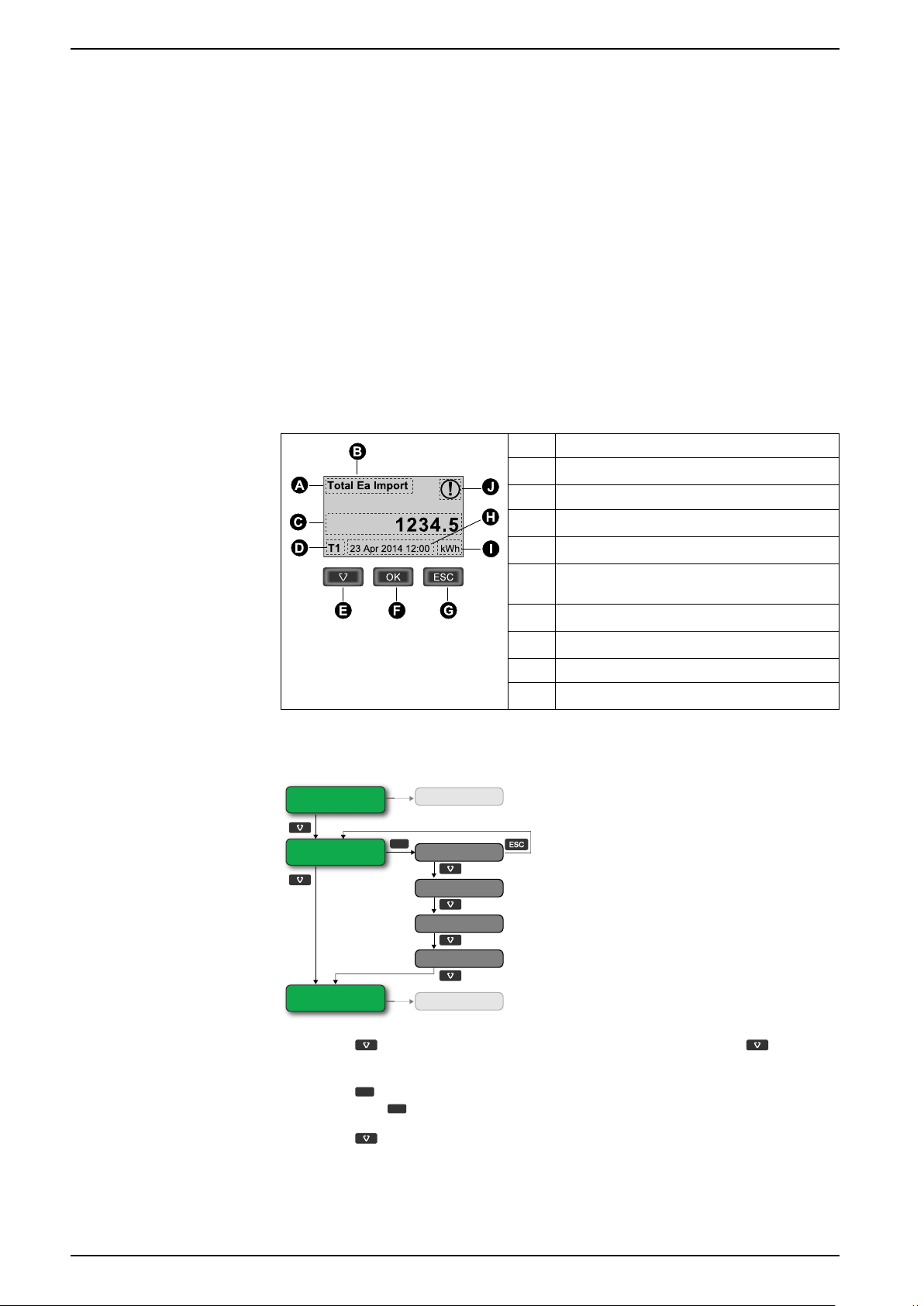
Data display
Data display screen overview
A Measurement
B Ea / Er = active / reactive energy (if available)
Example: navigating the display screens
C Value
D Active tariff (if applicable)
E Scroll through the available screens
F View more screens related to the measurement
category (if available)
G Go back to previous screen
H Date and time (if applicable)
I Unit
J Icon indicating date / time are not set
1. Press to scroll through the main display screens; then press to move
from Partial Reactive E to Tariffs to V & I.
2. Press
then press
18 DOCA0005EN-13
3. Press
to access additional screens related to main screen (if available);
to access screens for each of the available tariffs.
to scroll through these additional screens.
Page 19
Front panel display and meter setup iEM3100 / iEM3200 / iEM3300 series
Total Active E
Partial Active E
Reset
Tariffs
T1
T2
T3
T4
Information
Diagnosis
Total Active E
Partial Active E
Reset
V & I
Avg. L-L (L-N) Voltage
Phase 1 Current
Phase 2 Current
Phase 3 Current
Diagnosis
Active Power
Power Factor
Information
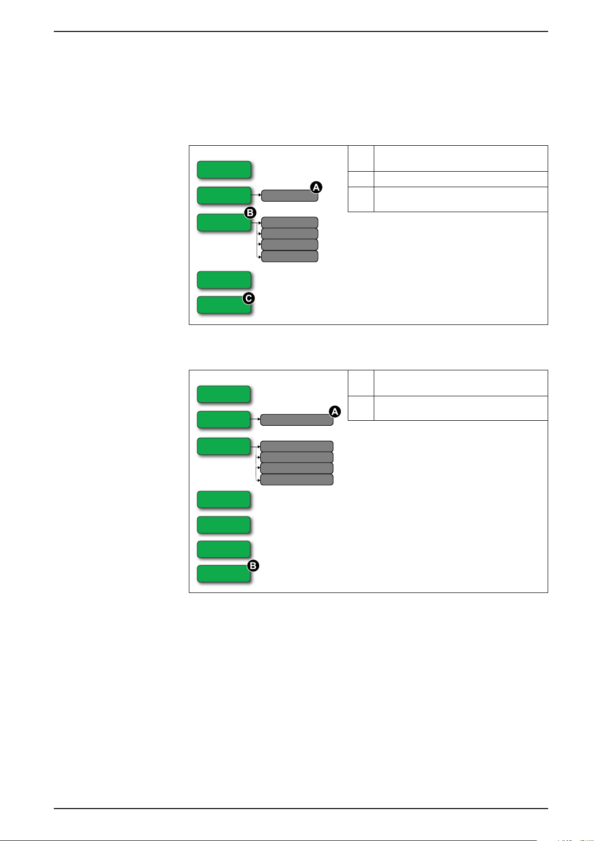
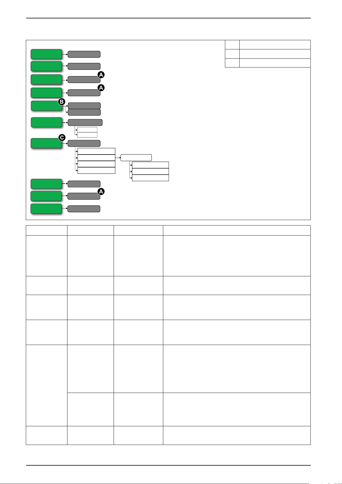
Data display screens
The following sections outline the data display screens available on the various
meter models.
Data display screens: iEM3100 / iEM3110 / iEM3115 / iEM3200 / iEM3210 / iEM3215 / iEM3300 / iEM3310
A Resets all energy measurements except total
active energy
B iEM3115 / iEM3215
C Diagnosis screen appears if there is a specific
event
Data display screens: iEM3150 / iEM3250 / iEM3350
A Resets all energy measurements except total
active energy
B Diagnosis screen appears if there is a specific
event
DOCA0005EN-13 19
Page 20
iEM3100 / iEM3200 / iEM3300 series Front panel display and meter setup
Total Er Import
Total Er Export
Partial Active E
Reset
Avg. L-L (L-N) Voltage
Phase 1 Current
Phase 2 Current
Phase 3 Current
V & I
Operation Time
Total Ea Import
Total Ea Export
Partial Reactive E
Reset
Tariffs
T1
T2
T3
T4
P, Q & S
Active Power
Reactive Power
Apparent Power
Power Factor
Frequency
PF & F
Diagnosis
Information
Partial Active E
876.2
kWh23-Apr-2012
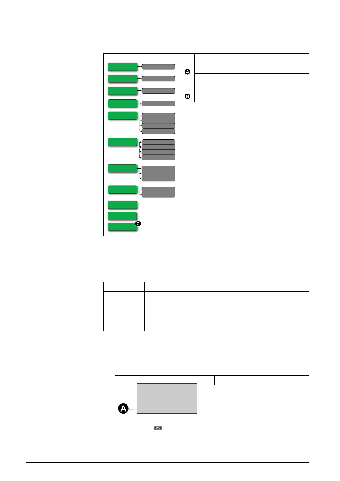
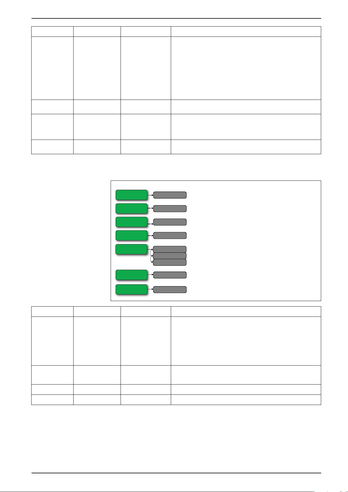
Data display screens: iEM3135 / iEM3155 / iEM3165 / iEM3175 / iEM3235 / iEM3255 / iEM3265 / iEM3275 /iEM3335 / iEM3355 / iEM3365 / iEM3375
A Import / export indicated for total active (Ea)
and total reactive (Er) energy. Other energy
measurements are import only
B Resets all energy measurements except total
active energy and total reactive energy
C Diagnosis screen appears if there is a specific
event
Resets
The following resets are available:
Reset Description
Partial energy Clears all active and reactive energy accumulated since the last reset.
This does not reset the total active and reactive energy accumulation.
Resetting accumulated energy using the display
Input metering Clears all input metering energy data.
You can only reset the input metering accumulation using software.
1. Navigate to the Partial Active E or Partial Reactive E screen. The screen
displays the date of the last reset. For example:
2. Press and hold . The Reset screen appears.
A Date of last reset
20 DOCA0005EN-13
Page 21
Front panel display and meter setup iEM3100 / iEM3200 / iEM3300 series
24 H
T1
T2
24 H
T1
T2
24 H
T1
T2
24 H
T1
T2
24 H
T3
24 H
T3
T4
3. PressOKto confirm the reset and enter the meter password when prompted.
NOTE: Regardless of the screen you use to access this reset,
accumulations of both Partial Active Energy and the Partial Reactive
Energy (if available) are cleared.
Multi Tariff feature
The Multi Tariff feature is available on iEM3115 / iEM3135 / iEM3155 /
iEM3165 / iEM3175 / iEM3215 / iEM3235 / iEM3255 / iEM3265 / iEM3275
/iEM3335 / iEM3355 / iEM3365 / iEM3375 meter models.
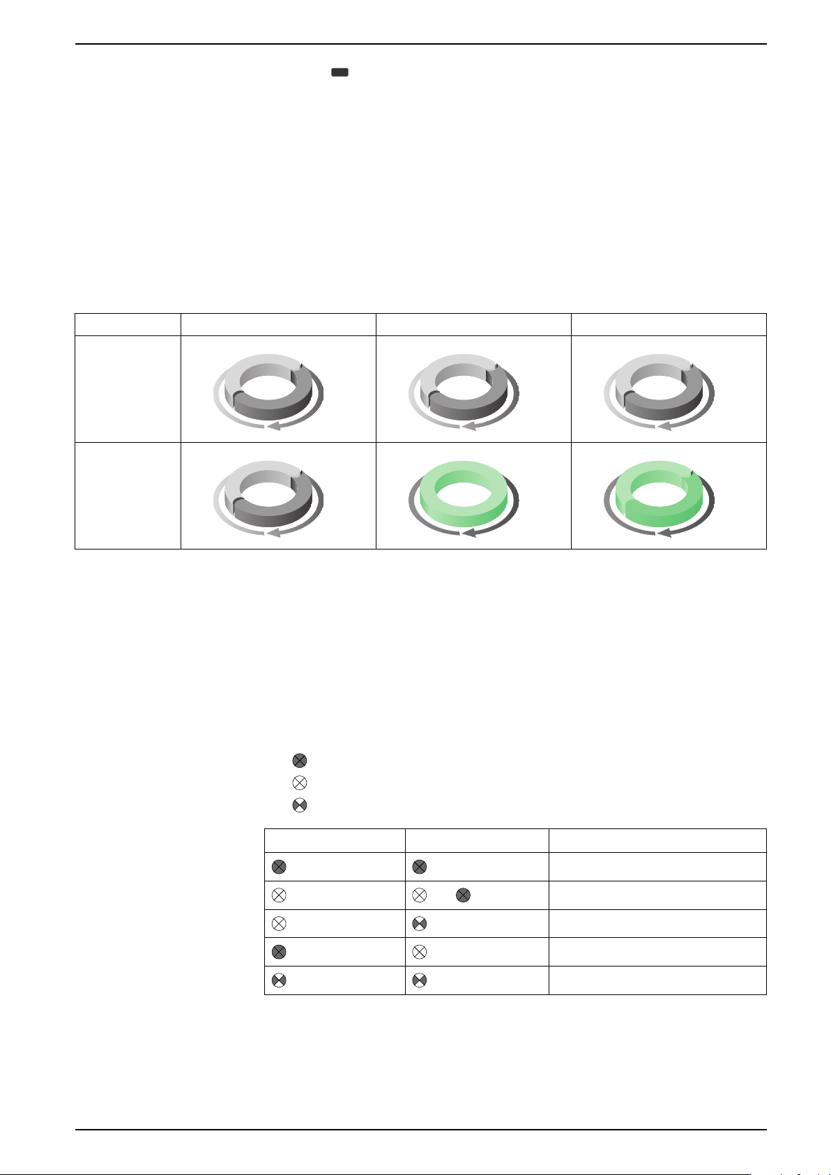
The table below illustrates how the tariffs operate according to the tariff selection
(2, 3 or 4 tariffs). These tariffs are stored in 4 different registers: T1, T2, T3 and T4.
2 tariffs 3 tariffs 4 tariffs
Weekday
Weekend
NOTE: If the tariff Control Mode is set to by Internal Clock, the start time of the
next tariff is the end time of the current tariff. For example, T2 start equals the
end of T1.
Meter status information
Two LEDs on the front panel indicate the current status of the device: the green
status LED and the yellow energy pulsing LED.
The icons in the table below indicate the LED state:
•
= LED is off
•
= LED is on
= LED is flashing
•
Status LED Energy pulsing LED Description
Off
1 s >
DOCA0005EN-13 21
On, no pulse counting
On, with pulse counting
Error, pulse counting stopped
Abnormal, with pulse counting
Page 22
iEM3100 / iEM3200 / iEM3300 series Front panel display and meter setup
Meter information
Meter information (for example, model and firmware version) is available on the
information screen. In display mode, press the down arrow until you reach the
information screen:
The device clock
Not applicable for iEM3100 / iEM3200 / iEM3300 meter models.
You must reset the time to account for any time change (for example, to switch the
time from standard time to daylight savings time).
Clock behavior: iEM3110 / iEM3210 / iEM3150 / iEM3250 / iEM3310 / iEM3350:
You are not prompted to set the date and time when the meter is powered up. You
can enter configuration mode to set the date and time. If you have not set the
clock, the following icon appears on the display:
When power is interrupted, the date and time are reset and you must enter
configuration mode to configure the clock, if you require time information.
.
Clock behavior: iEM3115 / iEM3135 / iEM3155 / iEM3165 / iEM3175 / iEM3215 / iEM3235 /
iEM3255 / iEM3265 / iEM3275 /iEM3335 / iEM3355 / iEM3365 / iEM3375:
You are prompted to set the date and time when the meter is powered up. Press
to skip this step if you do not want to set the clock (you can enter configuration
mode and set the date and time later, if required).
When the power is interrupted, the device retains its date and time information for
3 days. If power is interrupted for longer than 3 days, the device automatically
displays the screen to set Date & Time when power is restored.
Date/time format
The date is displayed in the following format: DD-MMM-YYYY.
The time is displayed using the 24-hour clock in the following format: hh:mm:ss.
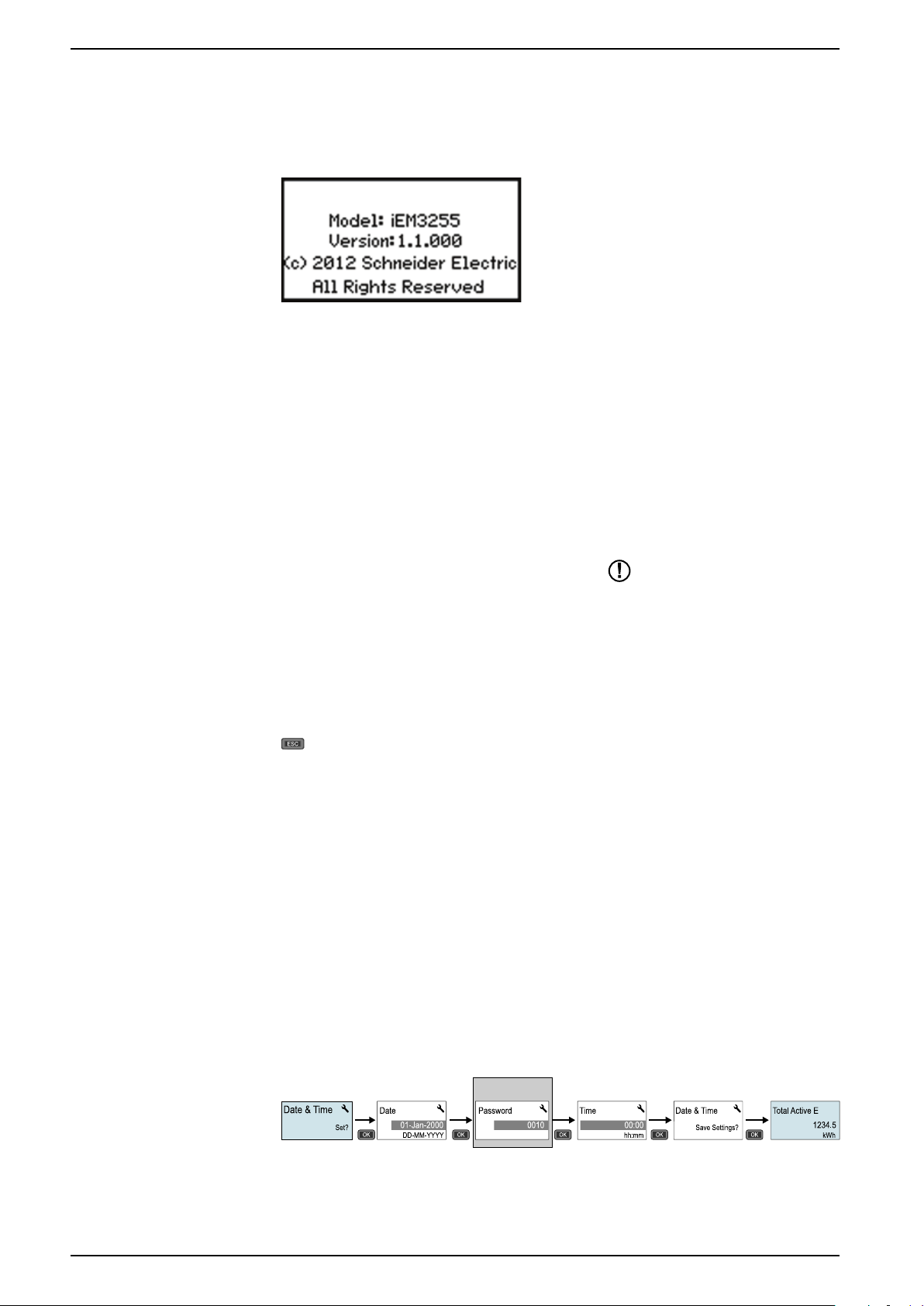
Setting the clock initially
The image below illustrates how to set the clock when you initially power up the
device or after a power failure. To set the clock during normal operation, refer to
Device configuration, page 23.
NOTE: Password entry is only required for meters that support a password.
22 DOCA0005EN-13
Page 23
Front panel display and meter setup iEM3100 / iEM3200 / iEM3300 series
Config
> 2 s
..\In. Pulse Const.
Overriding!
00500
Device configuration
The default factory settings (as applicable based on your model) are listed in the
table below:
Menu Factory settings
Wiring iEM3100 series: 3PH4W
iEM3200 series: 3PH4W; 3 CTs on I1, I2, and I3; Direct-No VT
iEM3300 series: 3PH4W
CT Ratio Varies depending on meter model
CT & VT Ratio Varies depending on meter model
Frequency 50 Hz
Date 1-Jan-2000
Time 00:00:00
Multi Tariffs Disable
Overload Alarm Disable
Digital Output Disable
Digital Input Input Status
Pulse Output 100 imp/kWh
Communication Varies depending on protocol
Com.Protection Enable
Contrast
Password 0010
5
Entering configuration mode
1. Press and holdOKand at the same time for about 2 seconds.
2. Enter the meter password, if prompted. The Access Counter screen
displays, indicating the number of times the configuration mode has been
accessed.
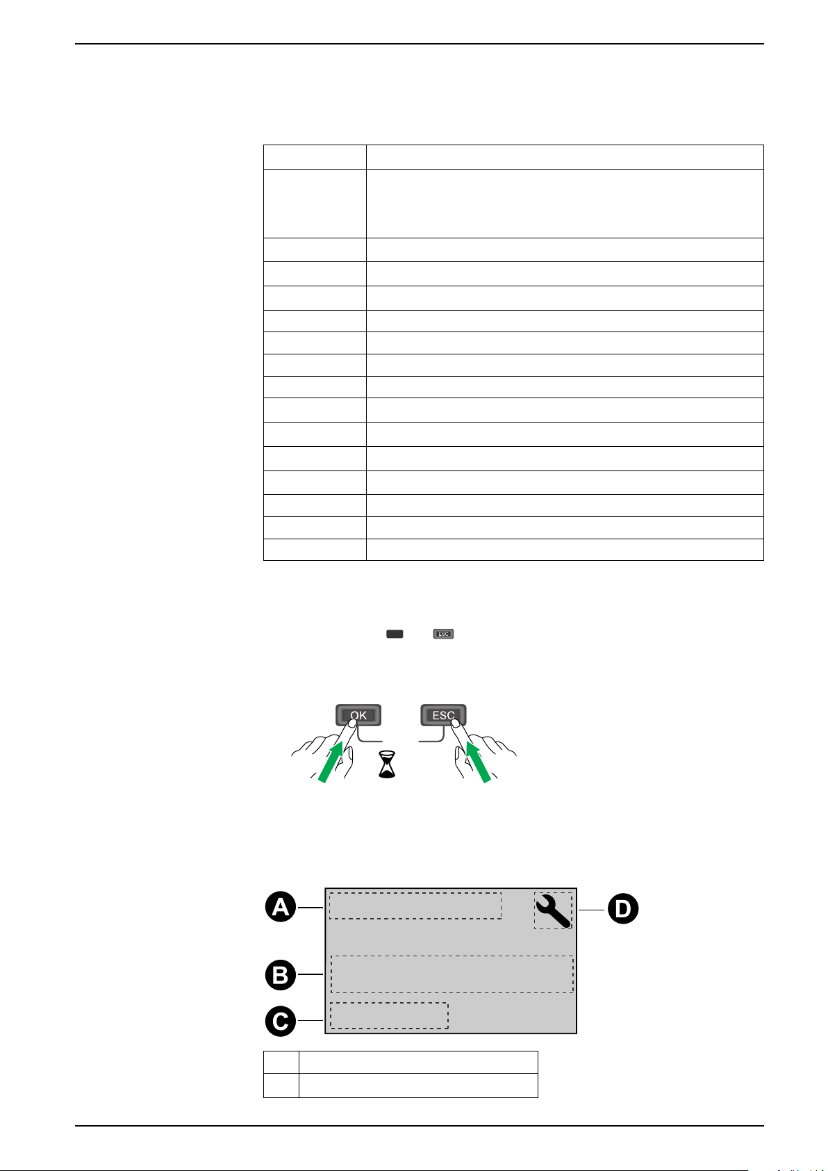
The front panel display in configuration mode
The image below illustrates the various elements of the display in configuration
mode:
A Parameter
B Setting
DOCA0005EN-13 23
Page 24
iEM3100 / iEM3200 / iEM3300 series Front panel display and meter setup
OK
OK
OK
C Indicates that the setting impacts the Multi
Tariff feature
D Configuration mode icon
Com. Protection setting
For meters with communications capabilities, you can enable or disable the Com.
Protection setting. If this setting is enabled, you must use the display to configure
certain settings (for example, wiring or frequency, etc.) and perform resets; you
cannot use communications.
The protected settings and resets are:
• Power system settings (for example, wiring, frequency, CT ratios)
• Date and time settings
• Multi Tariff settings
• Communications settings
• Partial energy reset
Modifying parameters
There are two methods for modifying a parameter, depending on the type of
parameter:
• Selecting a value in a list (for example, selecting 1PH2W L-N from a list of
• Modifying a numerical value, digit by digit (for example, entering a value for
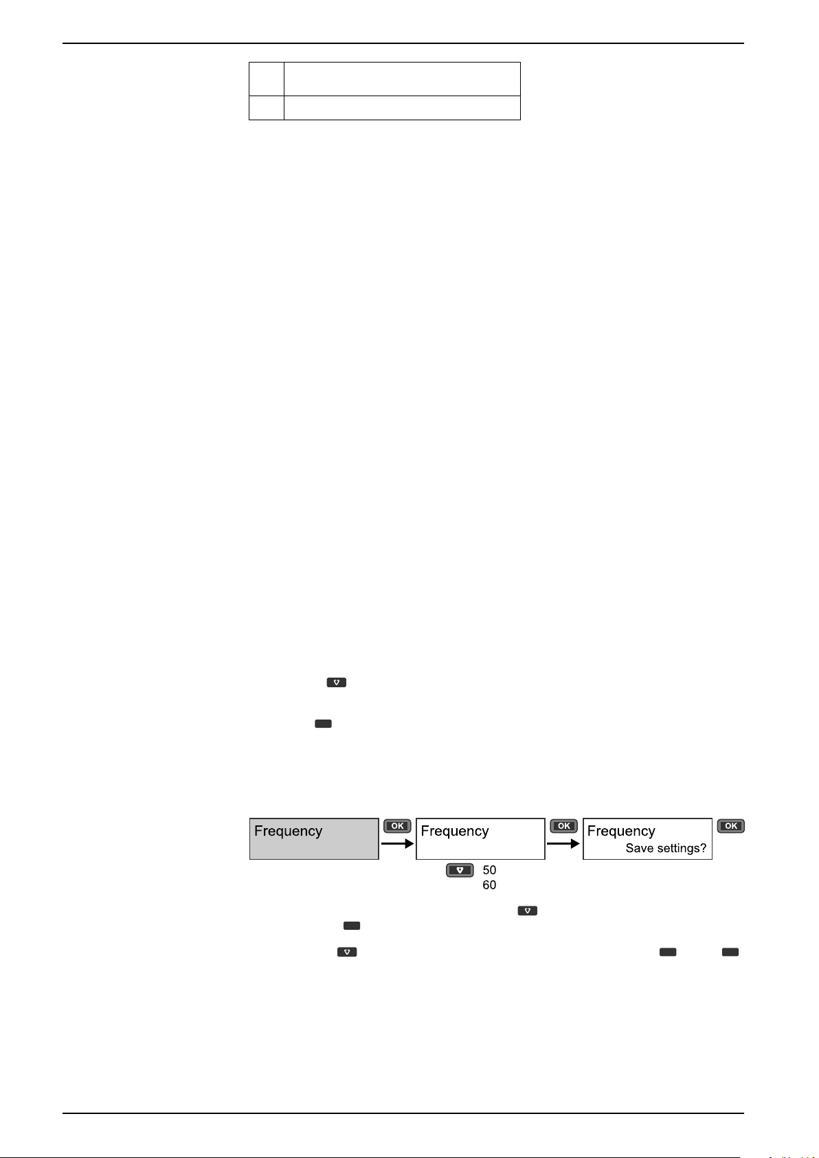
Selecting a value from a list
1. Use the button to scroll through the parameter values until you reach the
2. Press
Example: Configuring a list value
To set the nominal frequency of the meter:
available power systems), or
the date, time or VT primary).
NOTE: Before you modify any parameters, ensure that you are familiar with
the HMI functionality and navigation structure of your device in configuration
mode.
desired value.
to confirm the new parameter value.
1. Enter configuration mode and press the button until you reach Frequency
then press
2. Press the
to access the frequency configuration.
button to select the frequency you want then clickOK. Press
again to save your changes.
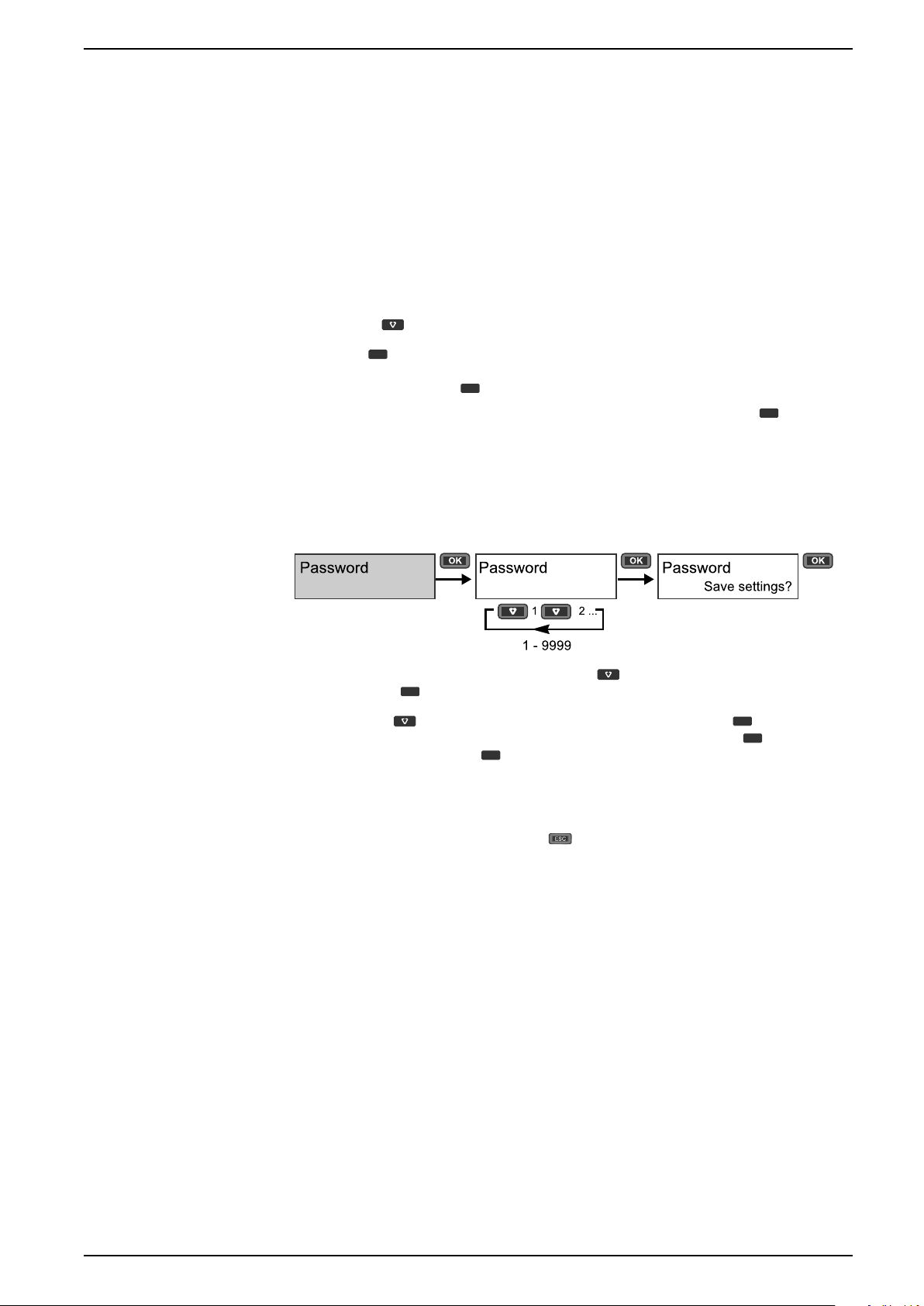
Modifying a numerical value
When you modify a numerical value, the digit on the far right side is selected by
default (except for Date/Time).
24 DOCA0005EN-13
Page 25
Front panel display and meter setup iEM3100 / iEM3200 / iEM3300 series
OK
OK
OK
OK
OK
OK
The parameters listed below are the only ones for which you set a numerical value
(if the parameter is available on your device):
• Date
• Time
• Pick Up Value for an overload alarm
• Voltage Transformer (VT) Primary
• Current Transformer (CT) Primary
• Password
• Address of the meter
To modify a numerical value:
1. Use the
2. Press
button to modify the selected digit.
to shift to next digit. Modify the next digit, if needed, or press okay to
move to the next digit. Continue to move through the digits until you reach the
last digit then press
If you enter an invalid setting for the parameter, when you press
again to confirm the new parameter value.
after
setting the left-most number, the cursor shifts back to the right-most number
so you can enter a valid value.
Example: configuring a numeric value
To set the password:
1. Enter configuration mode and press the button until you reach Password
then press
2. Press the
next digit to the left. When you reach the left-most digit, press
the next screen. Press
to access the password configuration.
button to increment the selected digit or pressOKto move to the
to move to
again to save your changes.
Cancelling an entry
To cancel the current entry, press the button. The change is canceled and the
screen reverts to the previous display.
Configuration mode menus
The images below show the configuration navigation for each device.
DOCA0005EN-13 25
Page 26
iEM3100 / iEM3200 / iEM3300 series Front panel display and meter setup
Wiring
Type
Frequency
Frequency
Date
Date
Time
Time
LED Energy
Pulse
LED Energy Pulse
Disable
by Internal Clock
Multi Tariffs
Control mode
Schedule
by 2 Tariffs
by 3 Tariffs
by 4 Tariffs
by Digital Input
by Communications
Pulse Output
Pulse Constant
Contrast
Contrast
Password
Password
Reset Config
Reset Config
Pulse Width
kWh
kVARh
Configuration menu for iEM3100 / iEM3110 / iEM3115 / iEM3300 / iEM3310
A iEM3110 / iEM3115 / iEM3310
B iEM3110 / iEM3310
C iEM3115
Section Parameter Options Description
3PH3W
3PH4W
Wiring Type
1PH2W L-N
Select the power system type the meter is wired to.
1PH2W L-L
1PH3W L-L-N
Frequency Frequency
50
Select the frequency of the electrical power system, in Hz.
60
Date
(iEM3110 /
iEM3115 /
Date DD-MMM-YYYY
Set the current date using the specified format.
iEM3310)
Time
(iEM3110 /
iEM3115 /
Time hh:mm Use the 24-hour format to set the time.
iEM3310)
100
Pulse Output
(iEM3110 /
iEM3310)
LED Energy
Pulse
Pulse Constant
(imp/kWh)
Pulse Width
(ms)
Energy
200
1000
1
10
20
50
100
200
300
kWh
kVARh
Set the pulses per kWh for the pulse output.
Set the pulse width (ON time).
Set the active energy and reactive energy.
26 DOCA0005EN-13
Page 27
Front panel display and meter setup iEM3100 / iEM3200 / iEM3300 series
Wiring
Type
Frequency
Frequency
Date
Date
Time
Time
Contrast
Contrast
Reset Config
Reset Config
Communication
Slave Address
Baud Rate
Parity
Section Parameter Options Description
Select the tariff control mode:
• Disable: the Multi Tariff function is disabled.
• by Digital Input: the digital input is associated with the Multi Tariff
Multi Tariffs
(iEM3115)
Control Mode
Disable
by Digital Input
by Internal Clock
function. A signal to the digital input changes the active tariff.
• by Internal Clock: the device clock controls the active tariff. If you
set the Control Mode to by Internal Clock, you must also
configure the schedule. Set the time when each tariff period
starts, using the 24 hour clock format (00:00 to 23:59). The start
time of the next tariff is the end time of the current tariff. For
example, T2 start equals the end of T1.
Contrast Contrast 1 – 9
Password
(iEM3110 /
iEM3115 /
Password 0 – 9999
iEM3310)
Reset Config Reset Config
—
Configuration menu for iEM3150 / iEM3350
Increase or decrease the value to increase or decrease the display
contrast.
Sets the password for accessing the meter configuration screens and
resets.
Settings are reset to their defaults, except for Password. Meter
restarts.
Section Parameter Options Description
3PH4W
1PH2W L-N
Wiring Type
1PH2W L-L
Select the power system type the meter is wired to.
1PH3W L-L-N
3PH3W
1PH4W Multi L-N
Frequency Frequency
50
Select the frequency of the electrical power system, in Hz.
60
Date Date DD-MMM-YYYY
Time Time hh:mm
DOCA0005EN-13 27
Set the current date using the specified format.
Set the time using the 24-hour format.
Page 28

iEM3100 / iEM3200 / iEM3300 series Front panel display and meter setup
Section Parameter Options Description
Slave Address 1 – 247
19200
Communication
Baud Rate
Parity
Contrast Contrast 1 – 9
Reset Config Reset Config
38400
9600
Even
Odd
None
—
Set the address for this device. The address must be unique for each
device in a communications loop.
Select the speed for data transmission. The baud rate must be the
same for all devices in a communications loop.
Select None if the parity bit is not used. The parity setting must be the
same for all devices in a communications loop.
NOTE: Number of stop bits = 1.
Increase or decrease the value to increase or decrease the display
contrast.
Settings are reset to their defaults, except for Password. Meter
restarts.
28 DOCA0005EN-13
Page 29
Front panel display and meter setup iEM3100 / iEM3200 / iEM3300 series
Wiring
Type
Frequency
Frequency
Date
Date
Time
Time
Disable
by Internal Clock
Multi Tariffs
Control mode
Schedule
by 2 Tariffs
by 3 Tariffs
by 4 Tariffs
by Digital Input
by Communications
Disable
Enable
Overload Alarm
Alarm
Pick Up Value
Disable
Alarm
Digital Output
DO Function
Pulse Constant
Pulse (kWh)
Pulse (kVARh)
Com.Protection
Com.Protection
Contrast
Contrast
Password
Password
Reset Config
Reset Config
Input Status
Tariff Control
Digital Input
DI Function
In. Pulse Const.
Input Metering
Partial Reset
Pulse Width
Pulse Constant
Pulse Width
Communication
Slave Address
Baud Rate
Parity
Communication
Primary Addr.
Baud Rate
Communication
MAC Addr.
Baud Rate
Device ID
LED Energy
Pulse
LED Energy Pulse
kWh
kVARh
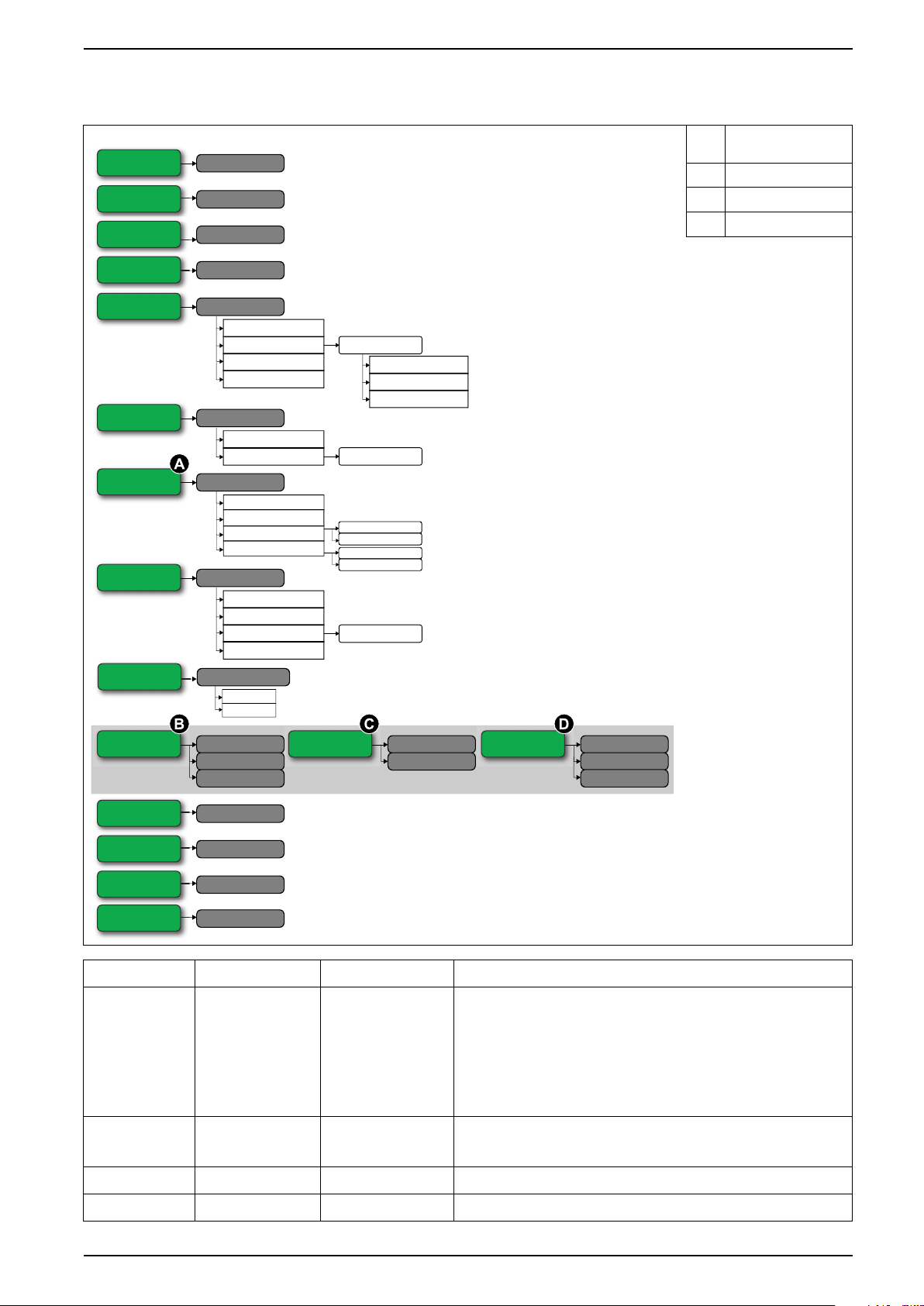
Configuration menu for iEM3135 / iEM3155 / iEM3165 / iEM3175 / iEM3335 / iEM3355 / iEM3365 / iEM3375
Not available on
A
iEM3175 / iEM3375
B iEM3155 / iEM3355
C iEM3135 / iEM3335
D iEM3165 / iEM3365
Section Parameter Options Description
Wiring Type
Frequency Frequency
3PH4W
1PH2W L-N
1PH2W L-L
1PH3W L-L-N
3PH3W
1PH4W Multi L-N
50
Select the power system type the meter is wired to.
Select the frequency of the electrical power system, in Hz.
60
Date Date DD-MMM-YYYY
Time Time hh:mm
Set the current date using the specified format.
Set the time using the 24-hour format.
DOCA0005EN-13 29
Page 30

iEM3100 / iEM3200 / iEM3300 series Front panel display and meter setup
Section Parameter Options Description
Select the tariff control mode:
• Disable: the Multi Tariff function is disabled.
• by Communication: the active tariff is control by communications.
See the chapter for the applicable protocol for more information.
• by Digital Input: the digital input is associated with the Multi Tariff
function. A signal to the digital input changes the active tariff.
• by Internal Clock: the device clock controls the active tariff. If you
set the Control Mode to by Internal Clock, you must also
configure the schedule. Set the time when each tariff period
starts, using the 24 hour clock format (00:00 to 23:59). The start
time of the next tariff is the end time of the current tariff. For
example, T2 start equals the end of T1.
Select whether or not the Overload Alarm is enabled:
• Disable: the alarm is disabled.
• Enable: the alarm is enabled. If you enabled the Overload Alarm,
you must also configure the Pick Up Value in kW from 1 -
9999999.
Select how the digital output functions:
• Disable: the digital output is disabled.
• Alarm: the digital output is associated with the overload alarm. In
the event of trigger, the digital output remains in the ON state
until the alarm drop out point is crossed.
• Pulse (kWh): The digital output is associated with energy pulsing
(active energy). When this mode is selected, you can select the
energy parameter and set the Pulse Constant (imp/kWh) and the
Pulse Width (ms).
• Pulse (kVARh): The digital output is associated with energy
pulsing (reactive energy). When this mode is selected, you can
select the energy parameter and set the Pulse Constant (imp/
kVARh) and the Pulse Width (ms).
Multi Tariffs Control Mode
Overload Alarm Alarm
Digital Output
(Not available on
iEM3175 /
iEM3375)
DO Function
Disable
by Communication
by Digital Input
by Internal Clock
Disable
Enable
Disable
Alarm
Pulse (kWh)
Pulse (kVARh)
Digital Input
LED Energy
Pulse
Communication
(iEM3155 /
iEM3355)
Input Status
DI Function
Energy
Slave Address 1 – 247
Baud Rate
Parity
Primary Addr.
Tariff Control
Input Metering
Partial Reset
kWh
kVARh
19200
38400
9600
Even
Odd
None
0 – 255
Select how the digital input functions:
• Input status: the digital input records the status of the input, for
example, OF, SD of a circuit breaker.
• Tariff Control: the digital input is associated with the Multi Tariff
function. A signal to the digital input changes the active tariff.
• Input Metering: the digital input is associated with input metering.
The meter counts and records the number of incoming pulses. If
you set the DI Function to Input Metering, you must also
configure In. Pulse Constant.
• Partial Reset: a signal to the digital input initiates a partial reset.
Set the active energy and reactive energy.
Set the address for this device. The address must be unique for each
device in a communications loop.
Select the speed for data transmission. The baud rate must be the
same for all devices in a communications loop.
Select None if the parity bit is not used. The parity setting must be the
same for all devices in a communications loop.
NOTE: Number of stop bits = 1.
Set the address for this device. The address must be unique for each
device in a communications loop.
Communication
(iEM3135 /
iEM3335)
Baud Rate
2400
4800
9600
300
600
1200
Select the speed for data transmission. The baud rate must be the
same for all devices in a communications loop.
30 DOCA0005EN-13
Page 31

Front panel display and meter setup iEM3100 / iEM3200 / iEM3300 series
Wiring
Type
CT
CT Ratio
CT Secondary
CT Primary
Frequency
Frequency
Date
Date
Time
Time
Disable
by Internal Clock
Multi Tariffs
Control mode
Schedule
by 2 Tariffs
by 3 Tariffs
by 4 Tariffs
by Digital Input
by Communications
Pulse Output
Pulse Constant
Contrast
Contrast
Password
Password
Reset Config
Reset Config
Pulse Width
LED Energy
Pulse
LED Energy Pulse
kWh
kVARh
Section Parameter Options Description
MAC Addr. 1 – 127
Set the address for this device. The address must be unique for each
device in a communications loop.
9600
Communication
(iEM3165 /
iEM3365)
Baud Rate
19200
38400
57600
Select the speed for data transmission. The baud rate must be the
same for all devices in a communications loop.
76800
Device ID 0 – 4194303
Com.Protection Com.Protection
Enable
Disable
Contrast Contrast 1 – 9
Password Password 0 – 9999
Reset Config Reset Config
—
Set the Device ID for this device. Make sure the Device ID is unique in
your BACnet network.
Protects selected settings and resets from configuration via
communications.
Increase or decrease the value to increase or decrease the display
contrast.
Sets the password for accessing the meter configuration screens and
resets.
Settings are reset to their defaults, except for Password. Meter
restarts.
Configuration menu for iEM3200 / iEM3210 / iEM3215
A iEM3210 / iEM3215
B iEM3210
C iEM3215
DOCA0005EN-13 31
Page 32

iEM3100 / iEM3200 / iEM3300 series Front panel display and meter setup
Section Parameter Options Description
3PH3W
Type
Wiring
3PH4W
1PH2W L-N
1PH2W L-L
1PH3W L-L-N
Select the power system type the meter is wired to.
CT
CT Ratio
Frequency Frequency
Date
(iEM3210 /
iEM3215)
Time
(iEM3210 /
iEM3215)
Pulse Output
(iEM3210)
CT Secondary
CT Primary
Date DD-MMM-YYYY
Time hh:mm
Pulse Constant
(imp/kWh)
Pulse Width
(ms)
3CTs on I1, I2, I3
1 CT on I1
2 CTs on I1, I3
1
5
1 – 32767
50
60
0.01
0.1
1
10
100
500
50
100
200
300
Define how many current transformers (CT) are connected to the
meter and which terminals they are connected to.
Select the size of the CT secondary, in Amps.
Enter the size of the CT primary, in Amps.
Select the frequency of the electrical power system, in Hz.
Set the current date using the specified format.
Set the time using the 24-hour format.
Set the pulses per kWh for the pulse output.
Set the pulse width (ON time).
LED Energy
Pulse
Multi Tariffs
(iEM3215)
Contrast Contrast 1 – 9
Password
(iEM3210 /
iEM3215)
Reset Config Reset Config
Energy
Control Mode
Password 0 – 9999
kWh
kVARh
Disable
by Digital Input
by Internal Clock
by Communication
—
Set the active energy and reactive energy.
Select the tariff control mode:
• Disable: the Multi Tariff function is disabled.
• by Communication: the active tariff is control by communications.
See the chapter for the applicable protocol for more information.
• by Digital Input: the digital input is associated with the Multi Tariff
function. A signal to the digital input changes the active tariff.
• by Internal Clock: the device clock controls the active tariff. If you
set the Control Mode to by Internal Clock, you must also
configure the schedule. Set the time when each tariff period
starts, using the 24 hour clock format (00:00 to 23:59). The start
time of the next tariff is the end time of the current tariff. For
example, T2 start equals the end of T1.
Increase or decrease the value to increase or decrease the display
contrast.
Sets the password for accessing the meter configuration screens and
resets.
Settings are reset to their defaults, except for Password. Meter
restarts.
32 DOCA0005EN-13
Page 33

Front panel display and meter setup iEM3100 / iEM3200 / iEM3300 series
Frequency
Frequency
Date
Date
Time
Time
Contrast
Contrast
Reset Config
Reset Config
Communication
Slave Address
Baud Rate
Parity
Wiring
Type
VT
CT
CT & VT Ratio
CT Secondary
CT Primary
VT Secondary
VT Primary
Configuration menu for iEM3250
Section Parameter Options Description
3PH4W
1PH2W L-N
Type
1PH2W L-L
Select the power system type the meter is wired to.
1PH3W L-L-N
3PH3W
1PH4W Multi L-N
Wiring
VT
Direct-NoVT
Wye (3VTs)
Select how many voltage transformers (VT) are connected to the
electrical power system.
Delta (2VTs)
CT
3CTs on I1, I2, I3
1 CT on I1
Define how many current transformers (CT) are connected to the
meter and which terminals they are connected to.
2 CTs on I1, I3
CT Secondary
1
Select the size of the CT secondary, in Amps.
5
CT & VT Ratio
CT Primary
VT Secondary
VT Primary
1 – 32767
100
110
115
120
1 – 1000000
Enter the size of the CT primary, in Amps.
Select the size of the VT secondary, in Volts.
Enter the size of the VT primary, in Volts.
Frequency Frequency
50
Select the frequency of the electrical power system, in Hz.
60
Date Date DD-MMM-YYYY
Time Time hh:mm
DOCA0005EN-13 33
Set the current date using the specified format.
Set the time using the 24-hour format.
Page 34

iEM3100 / iEM3200 / iEM3300 series Front panel display and meter setup
Section Parameter Options Description
Slave Address 1 – 247
19200
Communication
Baud Rate
Parity
Contrast Contrast 1 – 9
Reset Config Reset Config
38400
9600
Even
Odd
None
—
Set the address for this device. The address must be unique for each
device in a communications loop.
Select the speed for data transmission. The baud rate must be the
same for all devices in a communications loop.
Select None if the parity bit is not used. The parity setting must be the
same for all devices in a communications loop.
NOTE: Number of stop bits = 1.
Increase or decrease the value to increase or decrease the display
contrast.
Settings are reset to their defaults, except for Password. Meter
restarts.
34 DOCA0005EN-13
Page 35

Front panel display and meter setup iEM3100 / iEM3200 / iEM3300 series
Wiring
Type
VT
CT
CT & VT Ratio
CT Secondary
CT Primary
VT Secondary
VT Primary
Frequency
Frequency
Date
Date
Time
Time
Disable
by Internal Clock
Multi Tariffs
Control mode
Schedule
by 2 Tariffs
by 3 Tariffs
by 4 Tariffs
by Digital Input
by Communications
Disable
Enable
Overload Alarm
Alarm
Pick Up Value
Com.Protection
Com.Protection
Contrast
Contrast
Password
Password
Reset Config
Reset Config
Input Status
Tariff Control
Digital Input
DI Function
In. Pulse Const.
Input Metering
Partial Reset
Communication
Slave Address
Baud Rate
Parity
Communication
Primary Addr.
Baud Rate
Communication
MAC Addr.
Baud Rate
Device ID
Disable
Alarm
Digital Output
DO Function
Pulse Constant
Pulse (kWh)
Pulse (kVARh)
Pulse Width
Pulse Width
Pulse Constant
LED Energy
Pulse
LED Energy Pulse
kWh
kVARh
Configuration menu for iEM3235 / iEM3255 / iEM3265 / iEM3275
iEM3235 / iEM3255 /
A
iEM3265
B iEM3255
C iEM3235
D iEM3265
DOCA0005EN-13 35
Page 36

iEM3100 / iEM3200 / iEM3300 series Front panel display and meter setup
Section Parameter Options Description
3PH3W
3PH4W
Type
Wiring
VT
1PH2W L-N
1PH2W L-L
1PH3W L-L-N
1PH4W Multi L-N
Direct-NoVT
Wye (3VTs)
Delta (2VTs)
Select the power system type the meter is wired to.
Select how many voltage transformers (VT) are connected to the
electrical power system.
3CTs on I1, I2, I3
CT
CT Secondary
CT Primary
CT & VT Ratio
VT Secondary
VT Primary
Frequency Frequency
Date Date DD-MMM-YYYY
Time Time hh:mm
Multi Tariffs Control Mode
1 CT on I1
2 CTs on I1, I3
1
5
1 – 32767
100
110
115
120
1 – 1000000
50
60
Disable
by Communication
by Digital Input
by Internal Clock
Define how many current transformers (CT) are connected to the
meter and which terminals they are connected to.
Select the size of the CT secondary, in Amps.
Enter the size of the CT primary, in Amps.
Select the size of the VT secondary, in Volts.
Enter the size of the VT primary, in Volts.
Select the frequency of the electrical power system, in Hz.
Set the current date using the specified format.
Set the time using the 24-hour format.
Select the tariff control mode:
• Disable: the Multi Tariff function is disabled.
• by Communication: the active tariff is control by communications.
See the chapter for the applicable protocol for more information.
• by Digital Input: the digital input is associated with the Multi Tariff
function. A signal to the digital input changes the active tariff.
• by Internal Clock: the device clock controls the active tariff. If you
set the Control Mode to by Internal Clock, you must also
configure the schedule. Set the time when each tariff period
starts, using the 24 hour clock format (00:00 to 23:59). The start
time of the next tariff is the end time of the current tariff. For
example, T2 start equals the end of T1.
Select whether or not the Overload Alarm is enabled:
Overload Alarm Alarm
Digital Output
(iEM3235 /
iEM3255 /
iEM3265)
DO Function
Disable
Enable
Disable
Alarm
Pulse (kWh)
Pulse (kVARh)
• Disable: the alarm is disabled.
• Enable: the alarm is enabled. If you enabled the Overload Alarm,
you must also configure the Pick Up Value in kW from 1 -
9999999.
Select how the digital output functions:
• Disable: the digital output is disabled.
• Alarm: the digital output is associated with the overload alarm. In
the event of trigger, the digital output remains in the ON state
until the alarm drop out point is crossed.
• Pulse (kWh): The digital output is associated with energy pulsing
(active energy). When this mode is selected, you can select the
energy parameter and set the Pulse Constant (imp/kWh) and the
Pulse Width (ms).
• Pulse (kVARh): The digital output is associated with energy
pulsing (reactive energy). When this mode is selected, you can
select the energy parameter and set the Pulse Constant (imp/
kVARh) and the Pulse Width (ms).
NOTE: The iEM3275 does not have a digital output.
36 DOCA0005EN-13
Page 37

Front panel display and meter setup iEM3100 / iEM3200 / iEM3300 series
Section Parameter Options Description
Select how the digital input functions:
• Input status: the digital input records the status of the input, for
example, OF, SD of a circuit breaker.
• Tariff Control: the digital input is associated with the Multi Tariff
function. A signal to the digital input changes the active tariff.
• Input Metering: the digital input is associated with input metering.
The meter counts and records the number of incoming pulses. If
you set the DI Function to Input Metering, you must also
configure In. Pulse Constant.
• Partial Reset: a signal to the digital input initiates a partial reset.
Digital Input
DI Function
Input Status
Tariff Control
Input Metering
Partial Reset
LED Energy
Pulse
Communication
(iEM3255)
Communication
(iEM3235)
Communication
(iEM3265)
Energy
Slave Address 1 – 247
Baud Rate
Parity
Primary Addr.
Baud Rate
MAC Addr. 1 – 127
Baud Rate
Device ID 0 – 4194303
kWh
kVARh
19200
38400
9600
Even
Odd
None
0 – 255
2400
4800
9600
300
600
1200
9600
19200
38400
57600
76800
Set the active energy and reactive energy.
Set the address for this device. The address must be unique for each
device in a communications loop.
Select the speed for data transmission. The baud rate must be the
same for all devices in a communications loop.
Select None if the parity bit is not used. The parity setting must be the
same for all devices in a communications loop.
NOTE: Number of stop bits = 1.
Set the address for this device. The address must be unique for each
device in a communications loop.
Select the speed for data transmission. The baud rate must be the
same for all devices in a communications loop.
Set the address for this device. The address must be unique for each
device in a communications loop.
Select the speed for data transmission. The baud rate must be the
same for all devices in a communications loop.
Set the Device ID for this device. Make sure the Device ID is unique in
your BACnet network.
Com.Protection Com.Protection
Contrast Contrast 1 – 9
Password Password 0 – 9999
Reset Config Reset Config
Enable
Disable
—
Protects selected settings and resets from configuration via
communications.
Increase or decrease the value to increase or decrease the display
contrast.
Sets the password for accessing the meter configuration screens and
resets.
Settings are reset to their defaults, except for Password. Meter
restarts.
DOCA0005EN-13 37
Page 38

iEM3100 / iEM3200 / iEM3300 series Communications via Modbus
Communications via Modbus
Modbus communication overview
Modbus RTU protocol is available on iEM3150 / iEM3155 / iEM3250 / iEM3255
/ iEM3350 / iEM3355 meter models.
The information in this section assumes that you have an advanced
understanding of Modbus communications, your communications network and the
power system that your meter is connected to.
There are three different ways of using Modbus communication:
• By sending commands using the command interface
• By reading the Modbus registers
• By reading Device Identification
Modbus communications settings
Before communicating with the device using Modbus protocol, use the display to
configure the following settings:
Settings
Baud rate 9600 Baud
19200 Baud
38400 Baud
Parity Odd
Even
None
NOTE: Number of stop bits = 1
Address 1 – 247
Possible values
Communications LED indicator for Modbus devices
The yellow communications LED indicates the status of communication between
the meter and the master as follows:
If... Then...
The LED is flashing Communication with the device has been
The LED is off There is no active communication between the
established.
NOTE: If there is an error online, the LED
also flashes.
master and the slave
Modbus functions
Function list
The table below lists the supported Modbus functions:
38 DOCA0005EN-13
Page 39

Communications via Modbus iEM3100 / iEM3200 / iEM3300 series
Table format
Address Register Action
(R/W/WC)
Function code
Decimal Hexadecimal
3 0x03 Read Holding Registers
16 0x10 Write Multiple Registers
43/14 0x2B/0x0E Read Device Identification
Function name
For example:
• To read different parameters from the meter, use function 3 (Read).
• To change the tariff, use function 16 (Write) to send a command to the meter.
Register tables have the following columns:
Size Type Units Range Description
• Address: A 16-bit register address in hexadecimal. The address is the data
used in the Modbus frame.
• Register: A 16-bit register number in decimal (register = address + 1).
• Action: The read/write/write by command property of the register.
• Size: The data size in Int16.
• Type: The encoding data type.
• Units: The unit of the register value.
• Range: The permitted values for this variable, usually a subset of what the
format allows.
• Description: Provides information about the register and the values that
apply.
Unit table
The following data types appear in the Modbus register list:
Type Description Range
UInt16 16 bit unsigned integer 0 – 65535
Int16 16 bit signed integer -32768 to +32767
UInt32 32 bit unsigned integer 0 – 4 294 967 295
Int64 64 bit unsigned integer 0 – 18 446 744 073 709 551 615
UTF8 8 bit field Multibyte character encoding for Unicode
Float32 32 bit value Standard representation IEEE for floating
Bitmap
DATETIME See below table
— —
DATETIME format:
Word
1 Reserved R4 (0) Year (0 – 127)
2 0 Month (1 – 12) WD (0) Day (1 – 31)
15 14 13 12 11 10 9 8 7 6 5 4 3 2 1 0
Bits
number (with single precision))
—
3 SU (0) 0 Hour (0 – 23) iV 0 Minute (0 – 59)
DOCA0005EN-13 39
Page 40

iEM3100 / iEM3200 / iEM3300 series Communications via Modbus
DATETIME format: (Continued)
Word
4 Millisecond (0 – 59999)
R4 :
Year :
Month :
Day :
Hour :
Minute :
Millisecond :
WD (day of the week) :
SU (summer time) :
iV (validity of received data) :
15 14 13 12 11 10 9 8 7 6 5 4 3 2 1 0
Command interface
Command interface overview
Bits
Reserved Bit
7 bits (year from 2000)
4 bits
5 bits
5 bits
6 bits
2 octets
1 – 7: Sunday – Saturday
Bit to 0 if this parameter is not used
Bit to 0 if this parameter is not valid or not used
Command request
Slave
Number
1 – 247 16
Register
Address
5375
5376
Function
Code
Requested Command Number
Result
Command result codes:
• 0 = Valid Operation
• 3000 = Invalid Command
• 3001 = Invalid Parameter
• 3002 = Invalid Number of Parameters
• 3007 = Operation Not Performed
The command interface allows you to configure the meter by sending specific
command requests using Modbus function 16.
The table below describes a Modbus command request:
Command block
Register
Address
5250 (up to 5374)
Command Description
The command is made of a command number and a set
of parameters. See the detailed description of each
command in the command list.
NOTE: All the reserved parameters can be
considered as any value, e.g. 0.
Checking
The command result can be obtained by reading registers 5375 and 5376.
The table below describes the Command result:
Content
Size (Int16) Data (example)
1
1
2008 (Set Tariff)
0 (Valid Operation)
CRC
40 DOCA0005EN-13
Page 41

Communications via Modbus iEM3100 / iEM3200 / iEM3300 series
Command list
Set Date/Time
Command
Number
1003
Command
Number
2000
Action
(R/W)
W 1 UInt16
W 1 UInt16
W 1 UInt16
W 1 UInt16
W 1 UInt16
W 1 UInt16
W 1 UInt16
W 1 UInt16
Size
Type
Unit
— —
—
—
—
—
—
—
— —
Range Description
2000 – 2099 Year
1 – 12 Month
1 – 31 Day
0 – 23 Hour
0 – 59 Minute
0 – 59 Second
Set Wiring
Action
(R/W)
W 1 UInt16
W 1 UInt16
W 1 UInt16
W 1 UInt16
W 1 UInt16 Hz
W 2 Float32
W 2 Float32
W 2 Float32
W 1 UInt16
W 1 UInt16
W 2 Float32 V 1000000.0
W 1 UInt16 V
W 1 UInt16
W 1 UInt16 A 1 – 32767
W 1 UInt16
W 1 UInt16
W 1 UInt16
W 1 UInt16
Size
Type
Unit
— —
—
—
—
— —
— —
— —
— —
— —
—
— —
— —
— —
— —
Range Description
1, 3
2, 3, 4
0, 1, 2, 3,
11,13
50, 60
100, 110,
115, 120
1, 2, 3
(Reserved)
(Reserved)
(Reserved)
Number of phases
Number of wires
Power System Configuration:
0 = 1PH2W L-N
1 = 1PH2W L-L
2 = 1PH3W L-L-N
3 = 3PH3W
11 = 3PH4W
13 = 1PH4W L-N
Nominal Frequency
(Reserved)
(Reserved)
(Reserved)
(Reserved)
(Reserved)
VT Primary
NOTE: For iEM3250 / iEM3255. Reserved by
iEM3150 / iEM3155 / iEM3350 / iEM3355
VT Secondary
NOTE: For iEM3250 / iEM3255. Reserved by
iEM3150 / iEM3155 / iEM3350 / iEM3355
Number of CTs
NOTE: For iEM3250 / iEM3255. Reserved by
iEM3150 / iEM3155 / iEM3350 / iEM3355
CT Primary
NOTE: For iEM3250 / iEM3255. Reserved by
iEM3150 / iEM3155 / iEM3350 / iEM3355
(Reserved)
(Reserved)
(Reserved)
(Reserved)
DOCA0005EN-13 41
Page 42

iEM3100 / iEM3200 / iEM3300 series Communications via Modbus
Command
Number
Command
Number
2003
2038
2039
Action
(R/W)
W 1 UInt16
Size
Set Pulse Output (iEM3155 / iEM3255 / iEM3355)
Action
(R/W)
W 1 UInt16
W 1 UInt16
W 1 UInt16
W 2 Float32
W 1 UInt16
W 1 UInt16
W 2 Float32
W 1 UInt16
W 1 UInt16
W 2 Float32
W 1 UInt16
W 1 UInt16
W 1 UInt16
W 1 UInt16
W 1 UInt16
Size
Type
Type
— —
kWh
kVARh
—
pulse/kWh
— —
— —
— —
— —
— —
— —
— —
— —
ms
— —
imp/kWh
imp/KVARh
—
Unit
Unit
0, 1, 2
3, 6
0, 1
iEM3155 / iEM3355:
1, 10, 20, 100, 200,
1000
iEM3255:
0.01, 0.1, 1, 10, 100,
500
50, 100, 200, 300
0, 1
Range Description
VT Connection type:
0 = Direct Connect
1 = 3PH3W (2 VTs)
2 = 3PH4W (3 VTs)
NOTE: For iEM3250 / iEM3255. Reserved by
iEM3150 / iEM3155 / iEM3350 / iEM3355
Range Description
(Reserved)
Digital Output Control Mode Status:
3 = kWh
6 = kVARh
Pulse Output enable / disable:
0 = Disable
1 = Enable
Pulse constant
(Reserved)
(Reserved)
(Reserved)
(Reserved)
(Reserved)
(Reserved)
(Reserved)
(Reserved)
Pulse width
(Reserved)
LED energy pulse:
0 = kWh
1 = kVARh
Set Tariff (iEM3155 / iEM3255 / iEM3355)
Command
Number
2060
2008 W 1 UInt16
42 DOCA0005EN-13
Action
(R/W)
W 1 UInt16
W 1 UInt16
Size
Type
Unit
— —
—
— —
0, 1, 2, 4
Range Description
(Reserved)
Multi Tariff Mode:
0 = Disable Multi Tariff
1 = Use COM as Tariff Control (maximum 4 tariffs)
2 = Use Digital Input as Tariff Control (2 tariffs)
4 = Use Internal Clock as Tariff Control (maximum 4
tariffs)
(Reserved)
Page 43

Communications via Modbus iEM3100 / iEM3200 / iEM3300 series
Command
Number
Command
Number
6017
Action
(R/W)
W 1 UInt16
Size
Set Digital Input as Partial Energy Reset (iEM3155 / iEM3255 / iEM3355)
Action
(R/W)
W 1 UInt16
W 1 UInt16
Size
Input Metering Setup (iEM3155 / iEM3255 / iEM3355)
Type
Type
Unit
—
Unit
— —
—
Range Description
Tariff:
1 = T1
2 = T2
1 – 4
Range Description
0, 1
3 = T3
4 = T4
NOTE: You can only set the tariff using this
method if the Tariff Mode is set to by
Communication.
(Reserved)
Digital Input to Associate:
0 = Disable
1 = Enable
Command
Number
6014
Command
Number
Action
(R/W)
W 1 UInt16
W 1 UInt16
W 20 UTF8
W 2 Float32
W 1 UInt16
W 1 UInt16
Size
Type
Overload Alarm Setup (iEM3155 / iEM3255 / iEM3355)
Action
(R/W)
W 1 UInt16
W 1 UInt16
W 1 UInt16
W 1 UInt16
W 1 UInt16
Size
Type
Unit
— —
—
—
—
— —
—
Unit
— —
—
— —
— —
— —
Range Description
(Reserved)
1
String size ≤ 40
1 – 10000
0, 1
Range Description
9 Alarm ID
Input Metering Channel
Label
Pulse Weight
(Reserved)
Digital Input Association:
0 = Disable
1 = Enable
(Reserved)
(Reserved)
(Reserved)
(Reserved)
7000
W 1 UInt16
W 2 Float32
W 2 UInt32
W 2 Float32
W 2 UInt32
W 1 UInt16
—
—
— —
— —
— —
— —
0, 1
0.0 – 1e10
0 = Disable
1 = Enable
Pickup value
(Reserved)
(Reserved)
(Reserved)
(Reserved)
DOCA0005EN-13 43
Page 44

iEM3100 / iEM3200 / iEM3300 series Communications via Modbus
Command
Number
20000
20001 W 1 UInt16
Action
(R/W)
W 4 UInt16
W 1 UInt16
W 1 UInt16
W 1 UInt16
W 2 Float32
W 2 UInt32
W 1
Size
Bitmap
Communications Setup
Command
Number
5000
Action
(R/W)
W 1 UInt16
W 1 UInt16
W 1 UInt16
W 1 UInt16
W 1 UInt16
W 1 UInt16
W 1 UInt16
Size
Type
Type
Unit
— —
— —
— —
— —
— —
— —
—
— —
Unit
— —
— —
— —
—
—
—
— —
0, 1
1 – 247 Address
0, 1, 2
0, 1, 2
Range Description
(Reserved)
(Reserved)
(Reserved)
(Reserved)
(Reserved)
(Reserved)
Digital Output to Associate:
0 = Unassociated
1 = Associated
Acknowledge the Overload Alarm
Range Description
(Reserved)
(Reserved)
(Reserved)
Baud Rate:
0 = 9600
1 = 19200
2 = 38400
Parity:
0 = Even
1 = Odd
2 = None
(Reserved)
Reset Partial Energy Counters
Command
Number
2020 W 1 UInt16
Action
(R/W)
Size
Reset Input Metering Counter (iEM3155 / iEM3255 / iEM3355)
Command
Number
2023 W 1 UInt16
Action
(R/W)
Size
Type
Type
Unit
— —
Unit
— —
Range Description
(Reserved)
iEM3150 / iEM3250 / iEM3350: Partial Active Energy
and Phase Energy registers will be reset
iEM3155 / iEM3255 / iEM3355: Partial Active /
Reactive Energy, Energy by tariff and Phase Energy
registers will be reset.
Range Description
(Reserved)
44 DOCA0005EN-13
Page 45

Communications via Modbus iEM3100 / iEM3200 / iEM3300 series
Modbus register list
System
Address
0x001D 30 R 20 UTF8
0x0031 50 R 20 UTF8
0x0045 70 R 20 UTF8
0x0081 130 R 2 UInt32
0x0083 132 R 4 DATETIME
0x0087 136 R 5 UTF8
0x0664 1637 R 1 UInt16
0x0734 –
0x0737
Register
1845 –
1848
Action
(R/W/
WC)
R/WC 1 X 4 UInt16
Size
Type
Meter Setup and Status
Address
Register
Action
(R/W/WC)
Size
Type
—
—
—
—
—
—
—
—
Units
Units
Description
Meter Name
Meter Model
Manufacturer
Serial Number
Date of Manufacture
Hardware Revision
Present Firmware Version (DLF format): X.Y.ZTT
Date/Time:
Reg. 1845: Year (b6:b0) 0 – 99 (year from 2000
to 2099)
Reg. 1846: Month (b11:b8), Weekday (b7:b5),
Day (b4:b0)
Reg. 1847: Hour (b12:b8), Minute (b5:b0)
Reg. 1848: Millisecond
Description
0x07D3 2004 R 2 UInt32 Second
0x07DD 2014 R 1 UInt16
0x07DE 2015 R 1 UInt16
0x07DF 2016 R/WC 1 UInt16
0x07E0 2017 R/WC 1 UInt16 Hz
0x07E8 2025 R 1 UInt16
0x07E9 2026 R/WC 2 Float32 V
0x07EB 2028 R/WC 1 UInt16 V
0x07EC 2029 R/WC 1 UInt16
0x07ED 2030 R/WC 1 UInt16 A
—
—
—
—
—
Meter Operation Timer
NOTE: Not applicable for iEM3150 /
iEM3250 / iEM3350
Number of Phases
Number of Wires
Power System:
0 = 1PH2W L-N
1 = 1PH2W L-L
2 = 1PH3W L-L with N
3 = 3PH3W
11 = 3PH4W
13 = 1PH4W multi L with N
Nominal Frequency
Number VTs
NOTE: Not applicable for iEM3150 /
iEM3155 / iEM3350 / iEM3355
VT Primary
NOTE: Not applicable for iEM3150 /
iEM3155 / iEM3350 / iEM3355
VT Secondary
NOTE: Not applicable for iEM3150 /
iEM3155 / iEM3350 / iEM3355
Number CTs
NOTE: Not applicable for iEM3150 /
iEM3155 / iEM3350 / iEM3355
CT Primary
NOTE: Not applicable for iEM3150 /
iEM3155 / iEM3350 / iEM3355
DOCA0005EN-13 45
Page 46

iEM3100 / iEM3200 / iEM3300 series Communications via Modbus
Address
0x07EE 2031 R/WC 1 UInt16 A
0x07F3 2036 R/WC 1 UInt16
Register
Action
(R/W/WC)
Size
Type
—
Units
CT Secondary
VT Connection Type:
0 = Direct Connect
1 = 3PH3W (2 VTs)
2 = 3PH4W (3 VTs)
Energy Pulse Output Setup (iEM3155 / iEM3255 / iEM3355)
Address
0x0850 2129 R/WC 1 UInt16 Millisecond
0x0852 2131 R/WC 1 UInt16
0x0853 2132 R/WC 2 Float32
Register
Action
(R/W/
WC)
Size
Type
Units
Energy Pulse Duration
Digital Output Association
—
pulse/kWh Pulse Weight
0 = Disable
1 = DO1 enable for active energy pulse output
Description
NOTE: Not applicable for iEM3150 /
iEM3155 / iEM3350 / iEM3355
NOTE: Not applicable for iEM3150 /
iEM3155 / iEM3350 / iEM3355
Description
Command Interface
Address
0x1481 5250 R/W 1 UInt16
0x1483 5252 R/W 1 UInt16
0x14FD 5374 R/W 1 UInt16
0x14FE 5375 R 1 UInt16
0x14FF 5376 R 1 UInt16
0x1500 5377 R/W 1 UInt16
0x157A 5499 R 1 UInt16
Register
Action
(R/W/
WC)
Size
Communication
Address
Register
Action
(R/W/
WC)
Size
Type
Type
—
—
—
—
—
—
—
Units
Units
Description
Requested Command
Command Parameter 001
Command Parameter 123
Command Status
Command Result codes:
0 = Valid Operation
3000 = Invalid Command
3001 = Invalid Parameter
3002 = Invalid Number of Parameters
3007 = Operation Not Performed
Command Data 001
Command Data 123
Description
0x1963 6500 R 1 UInt16
0x1964 6501 R/WC 1 UInt16
—
—
Protocol
0 = Modbus
Address
46 DOCA0005EN-13
Page 47

Communications via Modbus iEM3100 / iEM3200 / iEM3300 series
Address
0x1965 6502 R/WC 1 UInt16
0x1966 6503 R/WC 1 UInt16
Register
Action
(R/W/
WC)
Size
Type
Units
—
—
Input Metering Setup (iEM3155 / iEM3255 / iEM3355)
Address
0x1B77 7032 R/WC 20 UTF8
0x1B8B 7052 R/WC 2 Float32
0x1B8E 7055 R/WC 1 UInt16
Register
Action
(R/W/
WC)
Size
Type
Units
—
pulse/unit
—
Description
Baud Rate:
0 = 9600
1 = 19200
2 = 38400
Parity:
0 = Even
1 = Odd
2 = None
NOTE: Number of stop bits = 1
Description
Label
Pulse Constant
Digital Input Association:
0 = Disable for input metering
1 = Enable for input metering
Digital Input (iEM3155 / iEM3255 / iEM3355)
Address
0x1C69 7274 R 1 UInt16
0x22C8 8905 R 2
Register
Action
(R/W/
WC)
Size
Type
Bitmap
Digital Output (iEM3155 / iEM3255 / iEM3355)
Address
0x25C8 9673 R 1 UInt16
Register
Action
(R/W/
WC)
Size
Type
—
—
—
Units
Units
Description
Digital Input Control Mode:
0 = Normal (Input Status)
2 = Multi Tariff Control
3 = Input Metering
5 = All Energy Reset
Digital Input Status (only Bit 1 is used):
Bit 1 = 0, relay open
Bit 1 = 1, relay closed
Description
Digital Output Control Mode Status:
2 = Alarm
3 = Pulse (kWh)
6 = Pulse (kVARh)
0xFFFF = Disable
DOCA0005EN-13 47
Page 48

iEM3100 / iEM3200 / iEM3300 series Communications via Modbus
PF firmware updates (iEM3155 / iEM3255 / iEM3355)
Addition to PF Registers: Values ranging from +1 to -1
Address
0x0C77 3192 R 2 Float32
0x0C79 3194
0x0C7B 3196 R 1 UInt16
0x0C7C 3197
Register
Action
(R/W/
WC)
R 2 Float32
R 1 UInt16
Size
Type
Units
—
—
—
—
1PH4W Multi LN updates (iEM3155 / iEM3255 / iEM3355)
Addition of each phase reactive energy import register
Address
0xB047 45128 R 2 Float32 kVARh
0xB049 45130 R 2 Float32 kVARh
0xB04B 45132 R 2 Float32 kVARh
Register
Action
(R/W/
WC)
Size
Type
Units
You can access each phase reactive energy import values using INT64 or Float 32
register format.
Description
Power Factor Total IEC
Power Factor Total Lead Lag
Power Factor Total IEC
Power Factor Total Lead Lag
Description
Reactive Energy Delivered Phase A
Reactive Energy Delivered Phase B
Reactive Energy Delivered Phase C
Addition of each phase name register
Address
0xDEA7 57000 R 5 UTF8
0xDEAC 57005 R 5 UTF8
0xDEB1 57010 R 5 UTF8
Register
Action
(R/W/WC)
Size
Type
Addition of one command to set the each phase name
Command
Number
6018
Action
(R/W/
WC)
W 1 UInt16
W 5 UTF8
W 5 UTF8
W 5 UTF8
Size
Type
Units
— —
—
—
—
Addition to display: Each phase active/reactive values are
added to HMI
Units
—
—
—
Range Description
String size ≤ 10
String size ≤ 10
String size ≤ 10
Description
Phase 1 Name
Phase 2 Name
Phase 3 Name
(Reserved)
Phase 1 name Label
Phase 2 name Label
Phase 3 name Label
Default value
PH1 Eng Impt
PH2 Eng Impt
PH3 Eng Impt
NOTE: When the wiring configuration is 1PH4W Multi LN, the partial energy
reset through Digital Input or Command is not possible.
48 DOCA0005EN-13
Page 49

Communications via Modbus iEM3100 / iEM3200 / iEM3300 series
Meter Data
Current, voltage, power, power factor and frequency
Address
Current
0x0BB7 3000
0x0BB9 3002
0x0BBB 3004
0x0BC1 3010
Voltage
0x0BCB 3020
0x0BCD 3022
0x0BCF 3024
0x0BD1 3026
0x0BD3 3028
0x0BD5 3030
0x0BD7 3032
0x0BDB 3036
Power
0x0BED 3054 R 2 Float32 kW Active Power Phase 1
0x0BEF 3056 R 2 Float32 kW Active Power Phase 2
0x0BF1 3058 R 2 Float32 kW Active Power Phase 3
0x0BF3 3060 R 2 Float32 kW Total Active Power
0x0BFB 3068 R 2 Float32 kVAR
0x0C03 3076 R 2 Float32 kVA
Power Factor
0x0C0B 3084 R 2 Float32
Register
Action
(R/W/
WC)
R 2 Float32 A
R 2 Float32 A
R 2 Float32 A
R 2 Float32 A
R 2 Float32 V
R 2 Float32 V
R 2 Float32 V
R 2 Float32 V
R 2 Float32 V
R 2 Float32 V
R 2 Float32 V
R 2 Float32 V
Size
Type
—
Units
Description
I1: phase 1 current
I2: phase 2 current
I3: phase 3 current
Current Avg
Voltage L1-L2
Voltage L2-L3
Voltage L3-L1
Voltage L-L Avg
Voltage L1-N
Voltage L2-N
Voltage L3-N
Voltage L-N Avg
Total Reactive Power
NOTE: Not applicable for iEM3150 / iEM3250
/ iEM3350
Total Apparent Power
NOTE: Not applicable for iEM3150 / iEM3250
/ iEM3350
Total Power Factor:
-1 < PF < 0 = Quad 2, active power negative,
capacitive
-2 < PF < -1 = Quad 3, active power negative,
inductive
0 < PF < 1 = Quad 1, active power positive,
inductive
1 < PF < 2 = Quad 4, active power positive,
capacitive
Frequency
0x0C25 3110 R 2 Float32 Hz
Frequency
Energy, energy by tariff and input metering
Most energy values are available in both signed 64-bit integer and 32-bit floating
point format.
The energy and energy by tariff measurements listed below are preserved through
power failures.
DOCA0005EN-13 49
Page 50

iEM3100 / iEM3200 / iEM3300 series Communications via Modbus
Energy reset and active tariff information
Address
0x0CB3 3252 R 4 DATETIME
0x0DE1 3554 R 4 DATETIME
0x105E 4191 R/WC 1 UInt16
Address
Total Energy (cannot be reset)
0x0C83 3204 R 4 Int64 Wh
0x0C87 3208 R 4 Int64 Wh
0x0C93 3220 R 4 Int64 VARh
0x0C97 3224 R 4 Int64 VARh
Partial Energy
Register
Register
Action
(R/W/
WC)
Action
(R/W/
WC)
Size
Energy values – 64-bit integer
Size
Type
Type
Units
—
—
—
Units
Description
Energy Reset Date and Time
Input Metering Accumulation Reset Date and
Time
NOTE: Not applicable for iEM3150 /
iEM3250 / iEM3350
Multi Tariffs Energy Active Rate:
0: Multi Tariff disabled
1 to 4: rate A to rate D
NOTE: You can only set the tariff using this
method if the Tariff Mode is set to by
Communication.
NOTE: Not applicable for iEM3150 /
iEM3250 / iEM3350
Description
Total Active Energy Import
Total Active Energy Export
NOTE: Not applicable for iEM3150 /
iEM3250 / iEM3350
Total Reactive Energy Import
NOTE: Not applicable for iEM3150 /
iEM3250 / iEM3350
Total Reactive Energy Export
NOTE: Not applicable for iEM3150 /
iEM3250 / iEM3350
0x0CB7 3256 R 4 Int64 Wh
0x0CC7 3272 R 4 Int64 VARh
Phase Energy
0x0DBD 3518
0x0DC1 3522
0x0DC5 3526
Input Metering Counter
0x0DE5 3558 R 4 Int64 Unit
Energy by Tariff (iEM3155 / iEM3255 / iEM3355 only)
0x1063 4196
0x1067 4200
0x106B 4204
0x106F 4208
R 4 Int64 Wh
R 4 Int64 Wh
R 4 Int64 Wh
R 4 Int64 Wh
R 4 Int64 Wh
R 4 Int64 Wh
R 4 Int64 Wh
Partial Active Energy Import
Partial Reactive Energy Import
NOTE: Not applicable for iEM3150 /
iEM3250 / iEM3350
Active Energy Import Phase 1
Active Energy Import Phase 2
Active Energy Import Phase 3
Input Metering Accumulation
NOTE: Not applicable for iEM3150 /
iEM3250 / iEM3350
Rate A Active Energy Import
Rate B Active Energy Import
Rate C Active Energy Import
Rate D Active Energy Import
50 DOCA0005EN-13
Page 51

Communications via Modbus iEM3100 / iEM3200 / iEM3300 series
Energy values – 32-bit floating point
Address
Total Energy (cannot be reset)
0xB02B 45100 R 2 Float32 Wh
0xB02D 45102 R 2 Float32 Wh
0xB02F 45104 R 2 Float32 VARh
0xB031 45106 R 2 Float32 VARh
Partial Energy
0xB033 45108 R 2 Float32 Wh
0xB035 45110 R 2 Float32 VARh
Phase Energy
0xB037 45112
0xB039 45114
0xB03B 45116
Input Metering Counter
Register
Action
(R/W/
WC)
R 2 Float32 Wh
R 2 Float32 Wh
R 2 Float32 Wh
Size
Type
Units
Description
Total Active Energy Import
Total Active Energy Export
NOTE: Not applicable for iEM3150 /
iEM3250 / iEM3350
Total Reactive Energy Import
NOTE: Not applicable for iEM3150 /
iEM3250 / iEM3350
Total Reactive Energy Export
NOTE: Not applicable for iEM3150 /
iEM3250 / iEM3350
Partial Active Energy Import
Partial Reactive Energy Import
NOTE: Not applicable for iEM3150 /
iEM3250 / iEM3350
Active Energy Import Phase 1
Active Energy Import Phase 2
Active Energy Import Phase 3
0xB03D 45118 R 2 Float32 Unit
Energy by Tariff (iEM3155 / iEM3255 / iEM3355 only)
0xB03F 45120
0xB041 45122
0xB043 45124
0xB045 45126
R 2 Float32 Wh
R 2 Float32 Wh
R 2 Float32 Wh
R 2 Float32 Wh
Overload Alarm (iEM3155 / iEM3255 / iEM3355)
Address
0xAFC8 45001 R/WC 1
0xAFC9 45002 R/WC 2 Float32 kW
0xAFCB 45004 R/WC 1
0xAFCC 45005 R 1
0xAFCD 45006 R 1
Register
Action
(R/W/
WC)
Size
Type
Bitmap
Bitmap
Bitmap
Bitmap
—
—
—
—
Units
Input Metering Accumulation
NOTE: Not applicable for iEM3150 /
iEM3250 / iEM3350
Rate A Active Energy Import
Rate B Active Energy Import
Rate C Active Energy Import
Rate D Active Energy Import
Description
Overload Alarm Setup:
0x0000 = Disabled
0x0100 = Enabled
Pickup Setpoint
Digital Output to Associate:
0x0000 = Digital Output unassociated to overload
alarm
0x0100 = Digital Output associated to overload
alarm
Activated Status:
0x0000 = Alarm is inactive
0x0100 = Alarm is active
Unacknowledged Status:
DOCA0005EN-13 51
Page 52

iEM3100 / iEM3200 / iEM3300 series Communications via Modbus
Address
0xAFCE 45007 R 4 DATETIME
0xAFD2 45011 R 2 Float32 kW Last Alarm - Value
Register
Action
(R/W/
WC)
Size
Type
—
Units
Description
0x0000 = Historic alarm is acknowledged by the
user
0x0100 = Historic alarm is unacknowledged by the
user
Last Alarm - Time Stamp
Read Device Identification
The meters supports the Read Device Identification function with the mandatory
objects Vendor Name, Product Code, Firmware Revision, Vendor URL, Product
Range, Product Model and User Application Name.
Object ID Name / Description Length
0x00 Vendor Name 20 Schneider Electric
0x01 Product Code 20 Commercial reference The ProductCode value is identical to the
0x02 Firmware Revision 06 XXX.YYY.ZZZ
0x03 Vendor URL 20
0x04 Product Range 20 iEM3000
www.se.com —
Value Note
—
catalog number of each device
Ex: A9MEM3x55
—
—
0x05 Product Model 20 Product Model Ex: A9MEM3x55
0x06 User Application Name 20 User configurable Default = Product model
The Read Device ID codes 01, 02 and 04 are supported:
• 01 = request to get basic device identification (stream access)
• 02 = request to get regular device identification (stream access)
• 04 = request to get one specific identification object (individual access)
The Modbus request and response are compliant with the Modbus Application
Protocol Specification.
52 DOCA0005EN-13
Page 53

Communications via LonWorks iEM3100 / iEM3200 / iEM3300 series
Communications via LonWorks
LonWorks communications overview
LonWorks communications is available on iEM3175 / iEM3275 / iEM3375
meter models.
The information in this section assumes that you have an advanced
understanding of LonWorks communications, your communications network and
the power system that your device is connected to.
LonWorks communication implementation
External interface file (XIF)
The variables and configuration properties for the meter are documented in the
external interface file (XIF). The XIF file is loaded onto the meter where your LNS
(LonWorks Network Services) software can download it. You can also download
the XIF file from www.se.com if you need to manually add the XIF file to your
software.
The LonMaker plug-ins
The plug-ins allow you to configure the meter and view meter data in Echelon
LonMaker.
LED indicators for LonWorks meters
The LonWorks meters have two LonWorks status LEDs: the red service LED and
the green communications LED.
Red service LED
This LED provides the status of LonWorks operations.
LED state Description
The LED is off The meter is configured. It may be online or offline.
The LED is flashing The meter is not configured but has an application.
The LED is on
Green communications LED
• The meter is not configured and without an application, or
• There is a defective internal memory issue.
This LED provides the status of the meter’s communications with the network.
LED state Description
The LED is off Communication is not active.
The LED is flashing Communication is active.
Location of the service pin and Neuron ID
The service pin is located on the front panel. Press this when requested by your
LNS software in order to identify the meter to your LonWorks network.
DOCA0005EN-13 53
Page 54

iEM3100 / iEM3200 / iEM3300 series Communications via LonWorks
LON
C/-
DI
OK
ESC
Reset
Confi
g
Neuron ID: 000000000000
S/N: 0000000000
You can also find the Neuron ID on the meter label if you need to manually enter it
into your LNS software.
A Service pin
B Location of the Neuron ID on the front panel
Standard network variable types and configuration properties for reading data
The following sections outline the Standard Network Variable Types (SNVTs), the
Standard Configuration Property Types (SCPTs), and User Configuration Property
Types (UCPTs) that you can access to read data from the meter.
General variables
Network variable label
nviRequest SCPTpartNumber For LonWorks internal communication
nvoStatus SCPToemType For LonWorks internal communication
Type Description
System variables
Network variable label
nvoFileDirectory SNVT_address Configuration parameter file directory address (LonMark)
nvoResponse SNVT_count Command result (LonMark)
nvoErrors SNVT_state Device error status
nciMeterModel SNVT_str_asc
(SCPTpartNumber)
Type Description
Error bitmap: each bit of the bitmap provides error information about the
device. If value of the bit = 1, that error is active.
Bit0 = Code 101: EEPROM error
Bit1 = Code 102: No calibration table
Bit2 = Code 201: mismatch between frequency settings and frequency
measurements
Bit3 = Code 202: mismatch between wiring settings and wiring inputs
Bit4 = Code 203: phase sequence reversed
Bit5 = Not used
Bit6 = Code 205: Date and time have been reset due to a power failure
Bit7 = Not used
Bit8 = Code 207: Abnormal internal clock function
Bit9 = Internal data bus communications error
Bit10 – 15: Not used
Device model, stored as an ASCII string (for example, iEM3275)
nciMeterManf SNVT_str_asc
Manufacturer name (Schneider Electric)
(SCPToemType)
nciSerialNumber SNVT_str_asc
Device serial number
(SCPTserialNumber)
nciManfDateTime SNVT_time_stamp
54 DOCA0005EN-13
(SCPTmanfDate)
Date of manufacture
Page 55

Communications via LonWorks iEM3100 / iEM3200 / iEM3300 series
Network variable label
nciDevMajVer SCPTdevMajVer LonWorks firmware major version (for example, 2.xx)
nciDevMinVer SCPTdevMinVer LonWorks firmware minor version (for example, x.34)
nciMeterVersion SNVT_str_asc
(UCPTMeterVersion)
Type Description
This variable functions with nciDevMinVer to provide the device’s LonWorks
firmware version
This variable functions with nciDevMajVer to provide the device’s LonWorks
firmware version
Device firmware version, stored as an ASCII text string
Energy and energy by tariff measurements
Most energy values are available in both signed 32-bit integer and floating point
format. The SNVT is appended with _l for 32-bit integer values and _f for floating
point values.
For example, the SNVTs for total active energy import are as follows:
• 32-bit integer: SNVT_elec_kwh_l
• Floating point: SNVT_elec_whr_f
The energy and energy by tariff measurements listed below are preserved through
power failures.
Network variable label
nvoTotkWhImp SNVT_elec_kwh_l Total active energy import
nvoTotkWhExp SNVT_elec_kwh_l Total active energy export
nvoTotkVARhImp SNVT_elec_kwh_l Total reactive energy import
nvoTotkVARhExp SNVT_elec_kwh_l Total reactive energy export
nvoTotWhImp SNVT_elec_whr_f Total active energy import
nvoTotWhExp SNVT_elec_whr_f Total active energy export
nvoTotVARhImp SNVT_elec_whr_f Total reactive energy import
nvoTotVARhExp SNVT_elec_whr_f Total reactive energy export
nvoPartialkWh SNVT_elec_kwh_l Partial active energy import
nvoPartialkVARh SNVT_elec_kwh_l Partial reactive energy import
nvoPartialWh SNVT_elec_whr_f Partial active energy import
nvoPartialVARh SNVT_elec_whr_f Partial reactive energy import
nvoPh1kWh SNVT_elec_kwh_l Active energy import phase 1
nvoPh2kWh SNVT_elec_kwh_l Active energy import phase 2
nvoPh3kWh SNVT_elec_kwh_l Active energy import phase 3
nvoPh1Wh SNVT_elec_whr_f Active energy import phase 1
Type Description
nvoPh2Wh SNVT_elec_whr_f Active energy import phase 2
nvoPh3Wh SNVT_elec_whr_f Active energy import phase 3
nvoTariffActRate SNVT_count Active tariff:
0 = Multi Tariff feature is disabled
1 = rate A (tariff 1) active
2 = rate B (tariff 2) active
3 = rate C (tariff 3) active
4 = rate D (tariff 4) active
nvoTariffAkWh SNVT_elec_kwh_l Rate A (tariff 1) active energy import
nvoTariffBkWh SNVT_elec_kwh_l Rate B (tariff 2) active energy import
DOCA0005EN-13 55
Page 56

iEM3100 / iEM3200 / iEM3300 series Communications via LonWorks
Network variable label
nvoTariffCkWh SNVT_elec_kwh_l Rate C (tariff 3) active energy import
nvoTariffDkWh SNVT_elec_kwh_l Rate D (tariff 4) active energy import
nvoTariffAWh SNVT_elec_whr_f Rate A (tariff 1) active energy import
nvoTariffBWh SNVT_elec_whr_f Rate B (tariff 2) active energy import
nvoTariffCWh SNVT_elec_whr_f Rate C (tariff 3) active energy import
nvoTariffDWh SNVT_elec_whr_f Rate D (tariff 4) active energy import
nvoInMeterAcc SNVT_count_f Input metering accumulation
nvoRstEnergyDT SNVT_time_stamp Date and time of last energy reset
Type Description
Instantaneous (RMS) measurements
Network variable label
nvoActPowerPh1 SNVT_power_f Active power Phase 1
nvoActPowerPh2 SNVT_power_f Active power Phase 2
nvoActPowerPh3 SNVT_power_f Active power Phase 3
nvoActPowerSum SNVT_power_f Total active power
nvoRctPowerSum SNVT_power_f Total reactive power
Type Description
nvoAppPowerSum SNVT_power_f Total apparent power
nvoVoltsL1N SNVT_volt_f Voltage L1-N
nvoVoltsL2N SNVT_volt_f Voltage L2-N
nvoVoltsL3N SNVT_volt_f Voltage L3-N
nvoVoltsLNAvg SNVT_volt_f Average voltage line-to-neutral
nvoVoltsL1L2 SNVT_volt_f Voltage L1-L2
nvoVoltsL2L3 SNVT_volt_f Voltage L2-L3
nvoVoltsL3L1 SNVT_volt_f Voltage L3-L1
nvoVoltsLLAvg SNVT_volt_f Average voltage line-to-line
nvoCurrentPh1 SNVT_amp_f Phase 1 current
nvoCurrentPh2 SNVT_amp_f Phase 2 current
nvoCurrentPh3 SNVT_amp_f Phase 3 current
nvoCurrentAvg SNVT_amp_f Average current
nvoAvgPwrFactor SNVT_count_inc_f Total power factor
nvoFrequency SNVT_freq_f Frequency
Meter status information
You can read the following network variables to obtain configuration and status
information about the meter. For information on configuring the meter, see the
sections on meter configuration properties and the LonWorks plug-in.
Network variable label
Basic information and meter configuration
nvoDateTime SNVT_time_stamp Meter date and time (DD/MM/YYYY hh:mm:ss)
nvoOpTimer SNVT_count_32 Meter operation timer: the time in seconds since the meter was last powered
System configuration information
56 DOCA0005EN-13
SNVT / UCPT type Description
up
Page 57

Communications via LonWorks iEM3100 / iEM3200 / iEM3300 series
Network variable label
nciSystemType SNVT_count Power system configuration:
nciWireNum SNVT_count Number of wires
nciPhaseNum SNVT_count Number of phases
nciCtNum SNVT_count Number of CTs
nciVtNum SNVT_count Number of VTs
nciVtPrimary SNVT_count_32 VT Primary
nciVTSecondary SNVT_count VT Secondary
SNVT / UCPT type Description
0 = 1PH2W L-N
1 = 1PH2W L-L
2 = 1PH3W L-L with N
3 = 3PH3W
11 = 3PH4W
13 = 1PH4 wire multi L-N
2, 3, 4
1, 3
1, 2, 3
NOTE: Applicable only for iEM3275
0 – 10
NOTE: Applicable only for iEM3275
NOTE: Applicable only for iEM3275
NOTE: Applicable only for iEM3275
nciCtPrimary SNVT_count CT Primary
NOTE: Applicable only for iEM3275
nciCtSecondary SNVT_count CT Secondary
NOTE: Applicable only for iEM3275
nciVtConnType SNVT_count VT connection type:
0 = Direct connection, no VTs
1 = 3PH3W (2VTs)
2 = 3PH4W (3VTs)
nciNominalFreq SNVT_freq_hz System frequency
50, 60
Digital input configuration and status information
nciDICtrMode SNVT_count Digital input control mode:
0 = Normal (input status)
2 = Multi Tariff control
3 = Input metering
5 = All partial energy reset (configure to reset all partial energy logs)
nciDIPulseConst SNVT_count_32 Pulse constant (pulses/unit)
nvoDIStatus SNVT_count Digital input status (only Bit 1 is used):
0 = relay open
1 = relay closed
NOTE: The information provided by this variable only applies if the digital
input control mode is set to Input Status.
Alarm status
nvoAlmStatus SNVT_count Alarm status (only Bit 1 is used):
0 = Alarm is inactive
1 = Alarm is active
nvoAlmUnAckState SNVT_count Acknowledgement status (only Bit 1 is used):
0 = historic alarm is acknowledged by the user
1 = historic alarm is unacknowledged by the user
nvoAlmLastTime SNVT_time_stamp Timestamp of last alarm (DD/MM/YYYY hh:mm:ss)
DOCA0005EN-13 57
Page 58

iEM3100 / iEM3200 / iEM3300 series Communications via LonWorks
Network variable label
nvoAlmLastValue SNVT_power_f Value at last alarm
nciAlmEnable SNVT_count Overload alarm configuration:
nciAlmPkUpSetPt SNVT_power_f Active power alarm pickup setpoint in kW
SNVT / UCPT type Description
0 = disabled
1 = enabled
Resets
Network variable
label
nciRstPartEnergy SNVT_switch Resets all partial energy accumulators to 0:
Type Description
Partial active energy import (nvoPartialkWh,
nvoPartialWh)
Partial reactive energy import (nvoPartialkVARh,
nvoPartialVARh)
Rate A active energy import (nvoTariffAkWh,
nvoTariffAWh)
Rate B active energy import (nvoTariffBkWh,
nvoTariffBWh)
Rate C active energy import (nvoTariffCkWh,
nvoTariffCWh)
Rate D active energy import (nvoTariffDkWh,
nvoTariffDWh)
Active energy import phase 1 (nvoPh1kWh,
nvoPh1Wh)
Active energy import phase 2 (nvoPh2kWh,
nvoPh2Wh)
Active energy import phase 3 (nvoPh3kWh,
nvoPh3Wh)
Action
To reset, set the state field to 1.
nciRstInMeterAcc SNVT_switch Resets input metering accumulation
(nvoInMeterAcc) to 0
Meter configuration properties
You can configure the meter using the configuration properties listed in this
section. However, it is recommended that you use the Echelon LonMaker plug-in if
you are configuring the meter using LonWorks communications.
NOTE: If Com. Protection is enabled, you may receive an error response
when you try to configure the meter over communications.
Date/time setup
Function profile UCPT Struct Members Range / Options
year
month 1 – 12
nciCfgDateTime
UCPTDateTime
day 1 – 31
hour 0 – 23
minute 0 – 59
second 0 – 59
To reset, set the state field to 1.
2000 – 2099
58 DOCA0005EN-13
Page 59

Communications via LonWorks iEM3100 / iEM3200 / iEM3300 series
Basic setup
Function profile UCPT Struct Members Range / Options Description
nciCfgWiring UCPTWiring
Digital input setup
SystemType 0, 1, 2, 3, 11, 13
NominFreq 50, 60 Nominal frequency in Hz
VtPrimary 0 – 1000000.0 The minimum value for VtPrimary must be
VtSecondary 100, 110, 115, 120
CtNum 1, 2, 3
CtPrimary 1 – 32767
CtSecondary 1, 5
VtConnType 0, 1, 2 VT connection type:
0 = 1PH2W L-N
1 = 1PH2W L-L
2 = 1PH3W L-L with N
3 = 3PH3W
11 = 3PH4W
13 = 1PH4 wire multi L with N
equal to or greater than the value set for
VtSecondary
—
—
—
—
0 = Direct connection
1 = 3PH3W (2VTs)
2 = 3PH4W (3VTs)
Function profile UCPT Struct Members Range / Options Description
Associates the digital input to reset partial
energy data:
0 = Digital input is not associated with the
partial energy reset.
nciCfgDigitInpt UCPTDigitalInput
—
0, 1
1 = Digital input is associated with the partial
energy reset.
Setting this property to 1 also updates
nciDICtrlMode (UCPTDiCtrlMode) to All
Energy Reset
Input metering setup
Function profile UCPT Struct Members Range /
PulseWeight
nciCfgInptMetAcc UCPTInputMetering
DigitalAssociation
Options
1 – 10000
0, 1
Sets the pulse weight (1 – 10000 ms)
Setting this property also sets
nciDIPulseConst (UCPTDiPulseConst) to the
same value.
Associates the digital input with input
metering:
0 = Digital input is not associated with input
metering
1 = The digital input is associated with input
metering
Setting this property to 1 also updates
nciDICtrlMode (UCPTDiCtrlMode) to Input
Metering.
Description
DOCA0005EN-13 59
Page 60

iEM3100 / iEM3200 / iEM3300 series Communications via LonWorks
Overload alarm setup
Function profile UCPT Struct
nciCfgOvLoadAlm
nciCfgOvLoadAck
UCPTOverLoadAlarm
UCPTOverLoadAlmAck
AlmEnable
PkUpSetpoint
—
Multi Tariff setup
Function profile UCPT Struct
nciCfgCommTariff
nciCfgTariffSel
UCPTTariffMode
UCPTTariffSelect
Members
—
—
Members
Range /
Options
0, 1
1, 2, 3, 4
Range /
Options
0, 1
1 – 9999999
0, 1
Description
Enable or disable the overload alarm:
0 = Disabled
1 = Enabled
The pickup value for the overload alarm
Acknowledgement status (only Bit 1 is
used):
0 = historic alarm is acknowledged by the
user
1 = historic alarm is unacknowledged by the
user
Description
Set Multi Tariff control mode to Disabled or by
Communication
0 = Disabled
1 = by Communication
NOTE: To configure the Multi Tariff feature to
be controlled by the digital input or device
clock, use the HMI.
Set the active tariff
1 = Rate A (tariff 1)
2 = Rate B (tariff 2)
3 = Rate C (tariff 3)
4 = Rate D (tariff 4)
NOTE: You can only set the tariff using this
method if the Tariff Mode is set to by
Communication.
Network propagation rate setup
The following configuration properties help control network traffic by controlling the
rate at which variable values are sent to your LNS.
nci variable UCPTs / SCPTs Applies to... Description
• nciErrors
• nciAllEnergy
• nciAllPower
nciMaxNvSntPerSec
nciErrors SCPTmaxSendTime nvoErrors
UCPTNVUpdtLimit
• nciAllVoltage
• nciAllCurrent
• nciAllPowerFactor
• nciFrequency.
Limits the total number of updates sent per
second for listed nci variables.
If more than the specified number of updates are
queued to be sent out in any 1 second period, the
excess updates are delayed until the next second
to reduce network traffic. The number of updates
sent per second varies depending on the
connection type updates from network variables
that are not controlled by this configuration
property.
Maximum interval, in seconds, between
transmissions of error values to the network.
The value of the applicable variable is sent after
the interval has elapsed, regardless of whether or
not the value of the variable has changed. The
counter is reset to 0.
60 DOCA0005EN-13
Page 61

Communications via LonWorks iEM3100 / iEM3200 / iEM3300 series
nci variable UCPTs / SCPTs Applies to... Description
Floating-point energy
values:
• nvoTotWhImp
• nvoTotWhExp
• nvoTotVARhImp
• nvoTotVARhExp
• nvoPartialWh
nciAllEnergy
nciAllPower SCPTminSendTime
nciAllVoltage
SCPTminSendTime
SCPTminSendTime
• nvoPartialVARh
• nvoPh1Wh
• nvoPh2Wh
• nvoPh3Wh
• nvoTariffAWh
• nvoTariffBWh
• nvoTariffCWh
• nvoTariffDWh
• nvoActPowerPh1
• nvoActPowerPh2
• nvoActPowerPh3
• nvoActPower-Sum
• nvoRctPower-Sum
• nvoAppPower-Sum
• nvoVoltsL1N
• nvoVoltsL2N
• nvoVoltsL3N
• nvoVoltsLNAvg
• nvoVoltsL1L2
• nvoVoltsL2L3
• nvoVoltsL3L1
• nvoVoltsLLAvg
The minimum interval, in seconds, between
consecutive transmissions of the listed variable
values to the network.
No updates to the value of the applicable
variables are sent over the network until the
minimum interval has elapsed, regardless of
whether or not the value of the variable has
changed.
After an update is sent, the counter is reset to 0.
• nvoCurrentPh1
nciAllCurrent SCPTminSendTime
nciAllPowerFactor SCPTminSendTime
nciFrequency
SCPTminSendTime
• nvoCurrentPh2
• nvoCurrentPh3
• nvoCurrentAvg
nvoAvgPwrFactor
nvoFrequency
Echelon LonMaker plug-in for data display and meter configuration
The information in this section assumes that you have an advanced
understanding of system administration using Echelon LonMaker.
The LonMaker plug-in provides a graphical user interface where you can view
meter values and configure meter settings. Once you install and register the plugin with LonMaker, it opens instead of the default LonMaker browser when you
browse the meter in LonMaker.
To add devices to LonMaker, you need access to the device service pin when
commissioning the device or your need the device Neuron ID recorded in an
accessible location.
Installing and registering the LonMaker plug-in
Before you install the plug-in:
DOCA0005EN-13 61
Page 62

iEM3100 / iEM3200 / iEM3300 series Communications via LonWorks
• Download the plug-in and XIF file for your device from www.se.com or contact
your sales representative to obtain these files.
• Make sure Echelon LonMaker is closed.
1. Navigate to the location where you saved the plug-in. Extract the files if they
are in a .zip file.
2. Double-click setup.exe. A welcome screen appears. Click Next.
3. Select the installation folder where you want to install the plug-in. Click
Browse if you want to select a different location. Click Next. A confirmation
screen appears.
4. Click Next to begin the installation.
NOTE: If LonMaker is open, a message appears instructing you to close
LonMaker and restart the plug-in installation.
A screen appears when the installation is complete. Click Close.
5. Navigate to Start > Programs > Schneider Electric and select the
registration entry for the plug-in you installed (for example, Schneider
Electric iEM3275 Plugin Registration). The LNS Plugin Registration
dialog box appears, indicating that registration is complete.
Make sure that the plug-in appears in the list of registered plug-ins in
LonMaker before you try to connect to a meter using the plug-in. If it does not
appear, you may need to re-register the plug-in.
Once the plug-in is installed and registered, add the meter to LonMaker. You
can either read the template (.XIF) from the device during commissioning or
select the EnergyMeter5A or EnergyMeter63A template when you add the
device to LonMaker.
Browsing the meter using the LonMaker plug-in
In order to use the plug-in to view data and configure the meter:
• The plug-in must be installed and registered.
• The meter must be added to LonMaker and commissioned.
1. Open LonMaker.
2. Right-click the meter icon and select Browse. The meter plug-in appears.
NOTE: If the meter-specific plug-in does not open, the plug-in may not be
correctly registered or the meter may not be properly commissioned in
LonMaker. Double-check the registration and meter commissioning. Refer
to the Echelon LonMaker documentation for more information.
62 DOCA0005EN-13
Page 63

Communications via LonWorks iEM3100 / iEM3200 / iEM3300 series
LonMaker plug-in interface
The plug-in has the following tabs:
Tab name Description
Meter Info This tab provides basic information about the meter (for example, model and
Energy Measure This tab provides total and partial energy values as well as energy per phase
RMS Measure This tab provides power, current, and voltage values as well as frequency and
Meter Status This tab provides information on the settings and status of the digital input and
Meter Config This tab provides access to the meter configuration properties, allowing you to
Diagnostics This tab provides LonMaker diagnostics information related to the meter.
serial number) and any active error codes.
and energy by tariff information. You can also reset energy and input metering
accumulations on this tab.
power factor information.
alarms as well as existing power system settings.
configure power system, digital input, alarm, Multi Tariff and time settings.
NOTE: If you see a message that the configuration was unsuccessful,
make sure: 1) the meter is properly commissioned in LonMaker and the
plug-in is communicating with the meter, and 2) that Com. Protection is
disabled on the meter.
DOCA0005EN-13 63
Page 64

iEM3100 / iEM3200 / iEM3300 series Communications via M-Bus
Communications via M-Bus
M-Bus communications overview
Communications via M-Bus protocol is available on iEM3135 / iEM3235 /
iEM3335 meter models.
M-Bus is a master / slave communications protocol where the master initiates
transactions and the slave(s) respond with the requested information or action.
Data is transferred using hexadecimal telegrams.
The information in this section is intended for users with an advanced
understanding of M-Bus protocol, their communications network and their power
system.
Configuring basic communications settings
Before communicating with the meter via M-Bus protocol, use the HMI to
configure the following settings:
Setting Possible values
Key terms
Baud rate
Primary address 1 – 250
300
600
1200
2400
4800
9600
NOTE: For M-Bus communication, the device consumes 2 standard loads (2
Unit Loads or 2UL).
Term Definition
C-Field The control or function field of the telegram. It provides information about the
CI-Field The control information field of the telegram. It defines the type and sequence of
Fixed data
header
DIF Data information field. The DIF contains information about the function of the data
telegram, such as the direction of data flow (master to slave or slave to master),
the status of the data flow and the function of the message.
data to be transmitted.
Contains device and manufacturer identification information.
(for example, instantaneous versus maximum) and the data format (for example,
16-bit integer).
DIFE Data information field extension. A DIFE contain additional information about the
Master A device that issues commands and receives responses from slave devices.
Slave A device that provides information or performs actions in response to requests
VIF / VIFE Value information field and value information field extension. The VIF and VIFE
64 DOCA0005EN-13
data, such as tariff and subunit.
There can be only one master per serial network.
from the master.
contain information about the value (for example, whether it is an energy or power
value).
The meter uses both primary VIFE (as detailed in the M-Bus protocol
documentation) and manufacturer-specific VIFE.
Page 65

Communications via M-Bus iEM3100 / iEM3200 / iEM3300 series
M-Bus protocol support
The meter supports the M-Bus protocol as follows:
• Mode 1 communications (least significant bit first).
• Telegram formats:
◦ Single character
◦ Short frame
◦ Long frame
• Function codes (C-field bits 3-0):
◦ SND_NKE: Initiates of communications between the master and slave.
◦ SND_UD: The master sends user data to the slave.
◦ REQ_UD2: The master requests Class 2 user data from the slave.
◦ RSP_UD: The slave sends requested data to the master.
• Secondary addressing in accordance with the M-Bus standard.
• Broadcast telegrams.
M-Bus protocol implementation
M-Bus tool for viewing data and configuring the meter
The M-Bus tool provides a graphical user interface where you can view meter data
and configure meter settings. To obtain the tool, go to www.se.com and search for
your meter model then select Downloads or contact your local Schneider Electric
representative.
Communications LED indicator for M-Bus meters
The communications LED indicates the status of the communications between the
meter and the network as follows:
LED state Description
The LED is flashing Communication with the meter has been established.
NOTE: The LED flashes even if there is a communications
error.
The LED is off There is no active communication.
Variable data structure telegram information
Fixed data header
Byte 1 – 4
Identification
No.
Serial number of
the meter in an
8-digit, BCD
coded format
The serial
number can also
be found on the
meter front panel
DOCA0005EN-13 65
Byte 5 – 6
Manufacturer
4CA3 hex =
Schneider
Electric
Byte 7
Version
Firmware version
of the
communications
board
10 = version 1.0
Byte 8
Medium
02 hex
(electricity)
Byte 9
Access No.
Counter of
successful
access attempts
Byte 8
Status
Indicates M-Bus
application
errors
Byte 11 – 12
Signature
Not used
Page 66

iEM3100 / iEM3200 / iEM3300 series Communications via M-Bus
14053100
YY
01053100
YY-13
31053100
YY+17
61053100
YY+47
Decoding secondary address and M-Bus serial number
Each M-Bus meter has a unique secondary address. The secondary address of a
meter includes 4 parts: serial number, M-Bus firmware version, medium, and
manufacturer.
The format of the secondary address is SSSSSSSSMAVVME. The decoding of
the secondary address is given below:
SSSSSSSS: Serial Number
MA: Manufacturer
VV: M-Bus Firmware Version
ME: Medium
Common Medium list:
01 = Oil
02 = Electricity
03 = Gas
04 = Heat
The main board serial number format is YYWWDNNN. The decoding of the M-Bus
serial number is given below followed with an example:
YY: Year
WW: Week
D: Day
NNN: Number
The following example distinguishes the M-Bus serial number for iEM3135 /
iEM3235 / iEM3335 meters.
Main Board SN
Data record header information
Data formats used by the meter (DIF bits 3 – 0)
NOTE: x in the hex value is determined by bits 7 – 4 of the DIF.
M-Bus SN
iEM3135 iEM3235 iEM3335
Format bin hex
No data 0000 x0
8-bit integer 0001 x1
16-bit integer 0010 x2
24-bit integer 0011 x3
32-bit integer 0100 x4
32-bit real 0101 x5
48-bit integer 0110 x6
64-bit integer 0111 x7
Variable length 1101 xD
66 DOCA0005EN-13
Page 67

Communications via M-Bus iEM3100 / iEM3200 / iEM3300 series
Data function types used by the meter (DIF bits 5 – 4)
Function type bin
Instantaneous 00
Maximum 01
Primary VIF used by the meter
NOTE: E denotes the extension bit; x in the hex value is determined by bits 7
– 4 of the VIF.
Primary VIF bin hex Description
Energy E000 0011 x3 Wh with a resolution of 10
kWh with a resolution of 10
Power E000 1110 xE kW with a resolution of 10
Time point E110 1101 xD Date and time in data type F, as detailed in
the M-Bus protocol documentation
0
in int64
3
in float32
3
Bus address E111 1010 xA Data type C (unsigned integer), as detailed
Primary VIFE 1111 1101 FD Indicates that the first VIFE is a primary VIF
Manufacturerspecific VIFE
1111 1111 FF Indicates that the next VIFE is
in the M-Bus protocol documentation
extension
manufacturer specific
Primary VIFE codes used by the meter
The primary VIFE codes in the table below are used by the meter when the VIF
equals FD hex (1111 1101 bin).
NOTE: E denotes the extension bit; x in the hex value is determined by bits 74 of the VIFE.
Primary VIFE
codes
Manufacturer E000 1010 xA
Model E000 1100 xC
Voltage E100 1001 x9 Volts with a resolution of 10
Current E101 1100 xC Amps with a resolution of 10
Digital output E001 1010 xA
Digital input E001 1011 xB
bin hex Additional information
—
—
0
0
—
—
Cumulation counter E110 0001 x1 Input metering accumulation
Error flag E001 0111 x7
—
Manufacturer-specific VIFE codes
The manufacturer-specific VIFE codes in the table below are used by the meter
when the VIF equals FF hex (1111 1111 bin).
NOTE: E denotes the extension bit; the hex value assumes E = 0.
Description bin hex
L1 value E000 0001 01
L2 value E000 0010 02
L3 value E000 0011 03
Export energy value E000 1001 09
DOCA0005EN-13 67
Page 68

iEM3100 / iEM3200 / iEM3300 series Communications via M-Bus
Description bin hex
Partial energy value E000 1101 0D
Average current E000 0000 00
L-N Avg E000 0100 04
L1-L2 E000 0101 05
L2-L3 E000 0110 06
L3-L1 E000 0111 07
L-L Avg E000 1000 08
Power Factor E000 1010 0A
Frequency E000 1011 0B
Energy reset date and time E000 1100 0C
Input metering reset date and time E000 1110 0E
Input metering accumulation E000 1111 0F
Active tariff (Energy active rate) E001 0000 10
Tariff control mode E001 0001 11
Meter operation timer E010 0000 20
Number of phases E010 0001 21
Number of wires E010 0010 22
Power system configuration E010 0011 23
Nominal frequency E010 0100 24
Number of VTs E010 0101 25
VT primary E010 0110 26
VT secondary E010 0111 27
Number of CTs E010 1000 28
CT Primary E010 1001 29
CT Secondary E010 1010 2A
VT connection type E010 1011 2B
Energy pulse duration E010 1100 2C
Digital output association with active energy
pulsing
Pulse weight E010 1110 2E
Pulse constant E010 1111 2F
Digital input association E011 0000 30
Digital input status E011 0010 32
E010 1101 2D
Overload alarm setup E011 0100 34
Pickup setpoint E011 0101 35
Digital output association with overload
alarm
Activated status E011 0111 37
Acknowledgment E011 1000 38
Date and time of last alarm E0111001 39
Value at last alarm E011 1010 3A
E011 0110 36
68 DOCA0005EN-13
Page 69

Communications via M-Bus iEM3100 / iEM3200 / iEM3300 series
Telegram information for data records
The following sections outline the telegram information used in data records. The
tables contain the following information (if applicable):
• Data format in hex (for example, 16-bit integer)
• Primary VIF in hex
• Primary VIFE codes in bin and hex
• Manufacturer-specific VIFE codes in bin and hex
Meter information
NOTE: E denotes the extension bit; the hex value assumes E = 0.
Data format Primary VIF Extension Description
bin hex
0D E000 1010 0A Manufacturer
18-bit ASCII = Schneider Electric
0D E000 1100 0C Model
0D E000 1110 0E Firmware version
03 E0001 0111 17 Meter error codes:
0 = Code 101: EEPROM error
1 = Code 102: No calibration table
2 = Code 201: Mismatch between frequency settings and frequency measurements
3 = Code 202: Mismatch between wiring settings and wiring inputs
4 = Code 203: Phase sequence reversed
5 = Code 204: Total active energy negative due to incorrect voltage or current connections
6 = Code 205: Date and time are reset due to a power failure
7 = Code 206: Pulse missing due to overspeed of energy pulse output
8 = Code 207: Abnormal internal clock function
9 = Internal data bus communications error
Energy and energy by tariff measurements (INT64 and FLOAT32)
The energy and energy by tariff measurements listed below are preserved through
power failures. An addition of energy values in FLOAT32 format have been
provided with the existing 64-bit registers.
NOTE: E denotes the extension bit; the hex value assumes E = 0.
Data
format
INT64
07
07
87 40 03
87 40 83
07
87 40 83
07
07
07
03
DIFE
—
—
—
—
—
—
— — — —
03
83
83
83
83
83
Primary
VIF
Primary VIFE
bin hex bin hex
— — — —
— —
— — —
— —
— —
— —
— —
— —
— —
Manufacturer-specific
VIFE
Total active energy import
E000 1001 09 Total active energy export
Total reactive energy import
E000 1001 09 Total reactive energy export
E000 1101 0D Partial active energy import
E000 1101 0D Partial reactive energy import
E000 0001 01 Active energy import phase 1
E000 0010 02 Active energy import phase 2
E000 0011 03 Active energy import phase 3
E001 0000 10 Active tariff
Description
DOCA0005EN-13 69
Page 70

iEM3100 / iEM3200 / iEM3300 series Communications via M-Bus
Data
format
87 10 03
87 20 03
87 30 03
87 80 10 03
07
04
04
FLOAT32
05
05
85 40 83
85 40 83
05
85 40 83
05
05
05
85 10 03
85 20 03
85 30 03
85 80 10 03
05
DIFE
— —
—
—
—
—
—
—
—
—
— —
ED
ED
03
83
83
83
83
83
Primary
VIF
Primary VIFE
bin hex bin hex
— — — —
— — — —
— — — —
— — — —
E110 0001 61
— —
— —
— — — —
— —
— — — —
— —
— —
— —
— —
— —
— —
— — — —
— — — —
— — — —
— — —
E110 0001 61
Manufacturer-specific
VIFE
— —
E000 1100 0C Date and time of last partial energy reset
E000 1110 0E Date and time of last input metering reset
E000 1001 09 Total active energy export
E000 1001 09 Total reactive energy export
E000 1101 0D Partial active energy import
E000 1101 0D Partial reactive energy import
E000 0001 01 Active energy import phase 1
E000 0010 02 Active energy import phase 2
E000 0011 03 Active energy import phase 3
— —
Description
0 = Multi Tariff feature is disabled
1 = rate A (tariff 1) active
2 = rate B (tariff 2) active
3 = rate C (tariff 3) active
4 = rate D (tariff 4) active
Rate A (tariff 1) active energy import
Rate B (tariff 2) active energy import
Rate C (tariff 3) active energy import
Rate D (tariff 4) active energy import
Input metering accumulation
Total active energy import
Total reactive energy import
Rate A (tariff 1) active energy import
Rate B (tariff 2) active energy import
Rate C (tariff 3) active energy import
Rate D (tariff 4) active energy import
Input metering accumulation
NOTE: The unit of FLOAT32 energy value is kWh/kVARh.
Instantaneous measurements
NOTE: E denotes the extension bit; the hex value assumes E = 0.
Data
format
05
05
05
05
85 40 2E
85 80 40 2E
05
05
DIFE
—
—
—
—
— —
— —
AE
AE
AE
2E
Primary
VIF
Primary VIFE
bin hex bin hex
— —
— —
— —
— — — —
— — — —
— — — —
E100 1001 C9 E000 0001 01 Voltage L1-N
E100 1001 C9 E000 0010 02 Voltage L2-N
70 DOCA0005EN-13
Manufacturer-specific
E000 0001 01 Active power Phase 1
E000 0010 02 Active power Phase 2
E000 0011 03 Active power Phase 3
VIFE
Description
Total active power
Total reactive power
Total apparent power
Page 71

Communications via M-Bus iEM3100 / iEM3200 / iEM3300 series
Data
format
05
05
05
05
05
05
05
05
05
05
05
05
DIFE
— —
— —
— —
— —
— —
— —
— —
— —
— —
— —
— — — —
— — — —
Primary
VIF
Meter status information
Primary VIFE
bin hex bin hex
E100 1001 C9 E000 0011 03 Voltage L3-N
E100 1001 C9 E000 0100 04 Average voltage line-to-neutral
E100 1001 C9 E000 0101 05 Voltage L1-L2
E100 1001 C9 E000 0110 06 Voltage L2-L3
E100 1001 C9 E000 0111 07 Voltage L3-L1
E100 1001 C9 E000 1000 08 Average voltage line-to-line
E101 1100 DC E000 0001 01 Phase 1 current
E101 1100 DC E000 0010 02 Phase 2 current
E101 1100 DC E000 0011 03 Phase 3 current
E101 1100 DC E000 0000 00 Average current
Manufacturer-specific
VIFE
E000 1010 0A Total power factor
E000 1011 0B Frequency
Description
Use the following information to read system and status information from the
meter. See the section regarding telegram information for meter configuration for
more information on writing to the meter.
Date and time information
NOTE: E denotes the extension bit; the hex value assumes E = 0.
Data
format
04 6D
06
—
Primary VIF
Manufacturer specific VIFE
bin hex
— —
E010 0000 20 Meter operation timer: the time in seconds since the device
Meter date and time (DD/MM/YYYY hh:mm:ss)
was last powered up
Power system configuration information
NOTE: E denotes the extension bit; the hex value assumes E = 0.
Data
format
03 E010 0011 23 Power system configuration:
03 E010 0010 22 Number of wires
03 E010 0001 21 Number of phases
03 E010 1000 29 Number of CTs
Manufacturer specific VIFE
bin hex
0 = 1PH2W L-N
1 = 1PH2W L-L
2 = 1PH3W L-L with N
3 = 3PH3W
11 = 3PH4W
13 = 1PH4 wire multi L with N
2, 3, 4
1, 3
1, 2, 3
NOTE: Applicable only for iEM3235
Description
Description
DOCA0005EN-13 71
Page 72

iEM3100 / iEM3200 / iEM3300 series Communications via M-Bus
Data
format
03 E010 0101 25 Number of VTs
03 E010 0110 26 VT Primary
03 E010 0111 27 VT Secondary
03 E010 1001 29 CT Primary
03 E010 1010 2A CT Secondary
03 E010 1011 2B VT connection type:
03 E010 0100 24 Nominal frequency
Manufacturer specific VIFE
bin hex
0 – 10
NOTE: Applicable only for iEM3235
NOTE: Applicable only for iEM3235
NOTE: Applicable only for iEM3235
NOTE: Applicable only for iEM3235
NOTE: Applicable only for iEM3235
0 = Direct connection, no VTs
1 = 3PH3W (2VTs)
2 = 3PH4W (3VTs)
50, 60
Description
Data
format
03 E001 1011 1B
05
02
03
03
05
03 E001 1010 1A
Primary VIFE Manufacturer specific VIFE Description
bin hex bin hex
— —
— —
— —
— —
— —
Digital input and output status information
NOTE: E denotes the extension bit; the hex value assumes E = 0.
— —
E010 1111 2F Pulse constant (pulses/unit)
E011 0010 32 Digital input status:
E011 0000 30 Digital input association with partial energy data reset
E010 1100 2C Energy pulse duration in milliseconds
E010 1110 2E Pulse weight of the digital output
— —
Digital input control mode:
0 = Normal (Input Status)
2 = Multi Tariff control
3 = Input metering
5 = All partial energy logs reset
0 = relay open
1 = relay closed
NOTE: This information only applies if the digital input
control mode is set to Input Status.
0 = Digital input is not associated with the partial energy
reset
1 = Digital input is associated with the partial energy reset
NOTE: This information only applies if the digital output
mode is set to energy pulsing.
NOTE: This information only applies if the digital output
mode is set to energy pulsing.
Digital output control mode
2 = for Alarm
3 = for Pulse (kWh)
0xFFFF = Disabled
72 DOCA0005EN-13
Page 73

Communications via M-Bus iEM3100 / iEM3200 / iEM3300 series
Data
format
03
02
Data
format
02
02
Primary VIFE Manufacturer specific VIFE Description
bin hex bin hex
— —
— —
E010 1101 2D Digital output association with energy pulsing:
0 = Digital output disabled
1 = for Pulse (digital output is associated with active energy
pulse output)
E011 0110 36 Digital output association with overload alarm:
0x0000 = digital output disabled
0x0100 = for Alarm (digital output is associated with the
overload alarm)
Alarm status information
NOTE: E denotes the extension bit; the hex value assumes E = 0.
Primary VIF
—
—
Manufacturer specific VIFE
bin hex
E011 0111 37 Alarm status:
0x0000 = Alarm is inactive
0x0100 = Alarm is active
E0111000 38 Acknowledgement status:
0x0000 = historic alarm is acknowledged by the user
0x0100 = historic alarm is unacknowledged by the user
Description
04 ED E0111001 39 Timestamp of last alarm (DD/MM/YYYY hh:mm:ss)
05
02
05
—
—
—
E0111010 3A Value at last alarm
E011 0100 34 Overload alarm configuration:
0x0000 = disabled
0x0100 = enabled
E011 0101 35 The pickup setpoint in kW for the overload alarm
Telegram decode information (all values are in hexadecimal)
st
1
telegram information
Byte No
1 1 68 Start character
2 1 F4 L-field, calculated from C field to last user data
3 1 F4 L-field, repeated
4 1 68 Start character
5 1 08 C-field, RSP_UD
6 1 XX A-field, address
7 1 72 CI-field, variable data respond, LSB first
Size Value
Description
8 – 11 4 XXXX Identification number, 8 BCD digits
12 – 13 2 4CA3 Manufacturer: SCH
14 1 00 Version
15 1 02 Medium, 02 = Electricity
16 1 X Number of accesses
17 1 X Status
18 – 19 2 0000 Signature (0000 = no encryption)
20 1 0D DIF size, special function
DOCA0005EN-13 73
Page 74

iEM3100 / iEM3200 / iEM3300 series Communications via M-Bus
Byte No
21 1 FD VIF extension of VIF-codes
22 1 0A Manufacturer name
23 1 12 String length
24 – 41 18 XXXXXXXXXXXXXX-
42 1 0D DIF size, special function
43 1 0D VIF extension of VIF-codes
44 1 FD Model
45 – 53 9 0C Meter model
54 1 XXXXXXXXX DIF size, special function
55 1 0D VIF extension of VIF-codes
56 1 FD Firmware version
57 – 64 8 0E Meter Firmware version
65 1 XXXXXXXX DIF size, 24 Bit Integer
66 1 03 VIF extension of VIF-codes
67 1 FD Error flags
68 – 70 3 17 Error flags (Diagnostics active bitmaps(1))
71 1 XXX DIF size, 32 Bit Real
72 1 05 VIF extension of VIF-codes
73 1 FD Current
74 1 DC VIF next byte is manufacturer specific
Size Value
Schneider Electric
XXXX
Description
75 1 FF L1
76 – 79 4 01 Current per phase,I1
80 1 XXXX DIF size, 32 Bit Real
81 1 05 VIF extension of VIF-codes
82 1 FD Current
83 1 DC VIF next byte is manufacturer specific
84 1 FF L2
85 – 88 4 02 Current per phase,I2
89 1 XXXX DIF size, 32 Bit Real
90 1 05 VIF extension of VIF-codes
91 1 FD Current
92 1 DC VIF next byte is manufacturer specific
93 1 FF L3
94 – 97 4 03 Current per phase,I3
98 1 XXXX DIF size, 32 Bit Real
99 1 05 VIF extension of VIF-codes
100 1 FD Current
101 1 DC VIF next byte is manufacturer specific
102 1 FF Average
103 – 106 4 00 Average current
107 1 XXXX DIF size, 32 Bit Real
108 1 05 VIF extension of VIF-codes
109 1 FD Voltage
110 1 C9 VIF next byte is manufacturer specific
74 DOCA0005EN-13
Page 75

Communications via M-Bus iEM3100 / iEM3200 / iEM3300 series
Byte No
111 1 FF L1-L2
112 – 115 4 05 Voltage,L1-L2
116 1 XXXX DIF size, 32 Bit Real
117 1 05 VIF extension of VIF-codes
118 1 C9 Voltage
119 1 FF VIF next byte is manufacturer specific
120 1 06 L2-L3
121 – 124 4 XXXX Voltage,L2-L3
125 1 05 DIF size, 32 Bit Real
126 1 FD VIF extension of VIF-codes
127 1 C9 Voltage
128 1 FF VIF next byte is manufacturer specific
129 1 07 L3-L1
130 – 133 4 XXXX Voltage,L3-L1
134 1 05 DIF size, 32 Bit Real
135 1 FD VIF extension of VIF-codes
136 1 C9 Voltage
Size Value
Description
137 1 FF VIF next byte is manufacturer specific
138 1 08 L-L Average
139 – 142 4 XXXX Average voltage, L -L
143 1 05 DIF size, 32 Bit Real
144 1 FD VIF extension of VIF-codes
145 1 C9 Voltage
146 1 FF VIF next byte is manufacturer specific
147 1 01 L1
148 – 151 4 XXXX Voltage, L1
152 1 05 DIF size, 32 Bit Real
153 1 FD VIF extension of VIF-codes
154 1 C9 Voltage
155 1 FF VIF next byte is manufacturer specific
156 1 02 L2
157 – 160 4 XXXX Voltage, L2
161 1 05 DIF size, 32 Bit Real
162 1 FD VIF extension of VIF-codes
163 1 C9 Voltage
164 1 FF VIF next byte is manufacturer specific
165 1 03 L3
166 – 169 4 XXXX Voltage, L3
170 1 05 DIF size, 32 Bit Real
171 1 FD VIF extension of VIF-codes
172 1 C9 Voltage
173 1 FF VIF next byte is manufacturer specific
174 1 04 L-N, average
DOCA0005EN-13 75
Page 76

iEM3100 / iEM3200 / iEM3300 series Communications via M-Bus
Byte No
175 – 178 4 XXXX Average, L-N
179 1 05 DIF size, 32 Bit Real
180 1 AE Power
181 1 FF VIF next byte is manufacturer specific
182 1 01 L1
183 – 186 4 XXXX Power,L1
187 1 05 DIF size, 32 Bit Real
188 1 AE Power
189 1 FF VIF next byte is manufacturer specific
190 1 02 L2
191 – 194 4 XXXX Power,L2
195 1 05 DIF size, 32 Bit Real
196 1 AE Power
197 1 FF VIF next byte is manufacturer specific
198 1 03 L3
199 – 202 4 XXXX Power,L3
203 1 05 DIF size, 32 Bit Real
204 1 2E Power
205 – 208 4 XXXX Total power
Size Value
Description
209 1 85 DIF size, 32 Bit Real
210 1 40 DIFE: Unit 1
211 1 2E Power
212 – 215 4 XXXX Reactive power
216 1 85 DIF size, 32 Bit Real
217 1 80 DIFE
218 1 40 DIFE: Unit 2
219 1 2E Power
220 – 223 4 XXXX Apparent power
224 1 05 DIF size, 32 Bit Real
225 1 FF VIF next byte is manufacturer specific
226 1 0A Power factor
227 – 230 4 XXXX Power factor value
231 1 05 DIF size, 32 Bit Real
232 1 FF VIF next byte is manufacturer specific
233 1 0B Frequency
234 – 237 4 XXXX Frequency value
238 1 07 DIF size, 64 Bit Integer
239 1 03 Energy
240 – 247 8 XXXXXXXX Total Active Energy Import
248 1 1F DIF, more records will follow in next telegram
249 1 X CS checksum, calculated from C field to last data
250 1 16 Stop character
76 DOCA0005EN-13
Page 77

Communications via M-Bus iEM3100 / iEM3200 / iEM3300 series
NOTE: Error flags illustrate:
0 = Inactive
1 = Active
Bit0 = Code 101
Bit1 = Code 102
Bit2 = Code 201
Bit3 = Code 202
Bit4 = Code 203
Bit5 = Code 204
Bit6 = Code 205
Bit7 = Code 206
Bit8 = Code 207
2ndtelegram information
Byte No
1 1 68 Start character
2 1 F6 L-field, calculated from C field to last user data
3 1 F6 L-field, repeated
4 1 68 Start character
5 1 08 C-field, RSP_UD
6 1 X A-field, address
7 1 72 CI-field, variable data respond, LSB first
8 – 11 4 XXXX Identification number, 8 BCD digits
12 – 13 2 4CA3 Manufacturer: SCH
14 1 00 Version
15 1 02 Medium, 02 = Electricity
16 1 X Number of accesses
17 1 00 Status
18 – 19 2 0000 Signature (0000 = no encryption)
20 1 07 DIF size, 64 Bit Integer
21 1 83 Energy
22 1 FF VIF next byte is manufacturer specific
Size Value
Description
23 1 09 Export energy
24 – 31 8 XXXXXXXX Total Active Energy Export
32 1 87 DIF size, 64 Bit Integer
33 1 87 DIFE: Unit1
34 1 40 Energy
35 – 42 8 03 Total Reactive Energy Import
43 1 XXXXXXXX DIF size, 64 Bit Integer
44 1 87 DIFE:Unit 1
45 1 40 Energy
46 1 83 VIF next byte is manufacturer specific
47 1 FF Export energy
48 – 55 8 09 Total Reactive Energy Export
56 1 XXXXXXXX DIF size, 32 Bit Integer
DOCA0005EN-13 77
Page 78

iEM3100 / iEM3200 / iEM3300 series Communications via M-Bus
Byte No
57 1 04 Date/Time
58 1 ED VIF next byte is manufacturer specific
59 1 FF Energy Reset
60 – 63 4 0C Energy Reset Date/Time
64 1 XXXX DIF size, 64 Bit Integer
65 1 07 Energy
66 1 83 VIF next byte is manufacturer specific
67 1 FF Partial energy
68 – 75 8 0D Partial Active Energy Import
76 1 XXXXXXXX DIF size, 64 Bit Integer
77 1 87 DIFE: Unit 1
78 1 40 Energy
79 1 83 VIF next byte is manufacturer specific
80 1 FF Partial Energy
81 – 88 8 0D Partial Reactive Energy Import
89 1 XXXXXXXX DIF size, 64 Bit Integer
Size Value
Description
90 1 07 Energy
91 1 83 VIF next byte is manufacturer specific
92 1 FF L1
93 – 100 8 01 Active Energy Delivered, L1
101 1 XXXXXXXX DIF size, 64 Bit Integer
102 1 07 Energy
103 1 83 VIF next byte is manufacturer specific
104 1 FF L2
105 – 112 8 02 Active Energy Delivered, L2
113 1 XXXXXXXX DIF size, 64 Bit Integer
114 1 07 Energy
115 1 83 VIF next byte is manufacturer specific
116 1 FF L3
117 – 124 8 03 Active Energy Delivered, L3
125 1 XXXXXXXX DIF size, 32 Bit Integer
126 1 04 Date/Time
127 1 ED VIF next byte is manufacturer specific
128 1 0E Input metering reset
129 – 132 4 XXXX Input Metering Accumulation Reset D/T
133 1 07 DIF size, 64 Bit Integer
134 1 FD VIF extension
135 1 61 Input Metering Accumulation Channel 1
136 – 143 8 XXXXXXXX Input Metering Channel 1 Value
144 1 03 DIF size, 24 Bit Integer
145 1 FF VIF next byte is manufacturer specific
146 1 10 Energy Active Rate
147 – 149 3 XXX Energy Active Rate, Number
78 DOCA0005EN-13
Page 79

Communications via M-Bus iEM3100 / iEM3200 / iEM3300 series
Byte No
150 1 87 DIF size, 64 Bit Integer
151 1 10 DIFE: Tariff 1
152 1 03 Energy
153 – 160 8 XXXXXXXX Active Energy Delivered Rate 1
161 1 87 DIF size, 64 Bit Integer
162 1 20 DIFE: Tariff 2
163 1 03 Energy
164 – 171 8 XXXXXXXX Active Energy Delivered Rate 2
172 1 87 DIF size, 64 Bit Integer
173 1 30 DIFE: Tariff 3
174 1 03 Energy
175 – 182 8 XXXXXXXX Active Energy Delivered Rate 3
183 1 87 DIF size, 64 Bit Integer
184 1 80 DIFE: Tariff 4
185 1 10 DIFE: Tariff 4
186 1 03 Energy
187 – 194 8 XXXXXXXX Active Energy Delivered Rate 4
Size Value
Description
195 1 04 DIF size, 32 Bit Integer
196 1 6D Date/Time
197 – 200 4 XXXX System date/time
201 1 03 DIF size, 24 Bit Integer
202 1 FF VIF next byte is manufacturer specific
203 1 2C Energy pulse duration
204 – 206 3 XXX Value, Energy pulse duration
207 1 03 DIF size, 24 Bit Integer
208 1 FF VIF next byte is manufacturer specific
209 1 2D Digital output association
210 – 212 3 XXX Value, Digital output association
213 1 05 DIF size, 32 Bit Real
214 1 FF VIF next byte is manufacturer specific
215 1 2E Pulse weight
216 – 219 4 XXXX Value, Pulse weight
220 1 05 DIF size, 32 Bit Real
221 1 FF VIF next byte is manufacturer specific
222 1 2F Pulse constant
223 – 226 4 XXXX Value, Pulse constant
227 1 03 DIF size, 24 Bit Integer
228 1 FF VIF next byte is manufacturer specific
229 1 30 Digital input association
230 – 232 3 XXX Value, Digital input association
233 1 03 DIF size, 24 Bit Integer
234 1 FD VIF extension
235 1 1B Digital input control mode
DOCA0005EN-13 79
Page 80

iEM3100 / iEM3200 / iEM3300 series Communications via M-Bus
Byte No
236 – 238 3 XXX Value, Digital input control mode
239 1 02 DIF size, 16 Bit Integer
240 1 FF VIF next byte is manufacturer specific
241 1 32 Digital input status
242 – 243 2 XX Value, Digital input status
244 1 03 DIF size, 24 Bit Integer
245 1 FD VIF extension
246 1 1A Digital output control mode status
247 – 249 3 XXX Value, Digital output control mode status
250 1 1F DIF, more records will follow in next telegram
251 1 X CS checksum, calculated from C field to last data
252 1 16 Stop character
Size Value
Description
3rdtelegram information
Byte No
1 1 68 Start character
2 1 F1 L-field, calculated from C field to last user data
3 1 F1 L-field, repeated
Size Value
Description
4 1 68 Start character
5 1 08 C-field, RSP_UD
6 1 X A-field, address
7 1 72 CI-field, variable data respond, LSB first
8 – 11 4 XXXX Identification Number, 8 BCD digits
12 – 13 2 4CA3 Manufacturer: SCH
14 1 00 Version
15 1 02 Medium, 02 = Electricity
16 1 X Number of accesses
17 1 00 Status
18 – 19 2 0000 Signature (0000 = no encryption)
20 1 02 DIF size, 16 Bit Integer
21 1 FF VIF next byte is manufacturer specific
22 1 34 Overload alarm setup
23 – 24 2 XX Value, Overload alarm setup
25 1 05 DIF size, 32 Bit Real
26 1 FF VIF next byte is manufacturer specific
27 1 FF Pickup setpoint
28 – 31 4 35 Value, Pickup setpoint
32 1 XXXX DIF size, 16 Bit Integer
33 1 02 VIF next byte is manufacturer specific
34 1 FF Digital output associate
35 – 36 2 36 Value, Digital output associate
37 1 XX DIF size, 16 Bit Integer
80 DOCA0005EN-13
Page 81

Communications via M-Bus iEM3100 / iEM3200 / iEM3300 series
Byte No
38 1 02 VIF next byte is manufacturer specific
39 1 FF Activated status
40 – 41 2 37 Value, Activated status
42 1 XX DIF size, 16 Bit Integer
43 1 02 VIF next byte is manufacturer specific
44 1 FF Unacknowledged status
45 – 46 2 38 Value, Unacknowledged status
47 1 XX DIF size, 32 Bit Integer
48 1 04 Date/Time
49 1 ED VIF next byte is manufacturer specific
50 1 FF Date time last alarm
51 – 54 4 39 Value, Date time last alarm
55 1 XXXX DIF size, 32 Bit Real
56 1 05 VIF next byte is manufacturer specific
57 1 FF Value last alarm
58 – 61 4 3A Value last alarm
62 1 XXXX DIF size, 48 Bit Integer
Size Value
Description
63 1 06 VIF next byte is manufacturer specific
64 1 FF Meter operation time
65 – 70 6 20 Value, Meter operation time
71 1 XXXXXX DIF size, 24 Bit Integer
72 1 03 VIF next byte is manufacturer specific
73 1 FF Num of phases
74 – 76 3 21 Value, Num of phases
77 1 XXX DIF size, 24 Bit Integer
78 1 03 VIF next byte is manufacturer specific
79 1 FF Num of wires
80 – 82 3 22 Value, Num of wires
83 1 XXX DIF size, 24 Bit Integer
84 1 03 VIF next byte is manufacturer specific
85 1 FF Power System Configuration
86 – 88 3 23 Value, Power System Configuration
89 1 XXX DIF size, 24 Bit Integer
90 1 03 VIF next byte is manufacturer specific
91 1 FF Nominal Frequency
92 – 94 3 24 Value, Nominal Frequency
95 1 05 DIF size, 32 Bit Real
96 1 03 Energy
97 – 100 4 XXXX Total Active Energy Import
101 1 05 DIF size, 32 Bit Real
102 1 83 Energy
103 1 FF VIF next byte is manufacturer specific
104 1 09 Export energy
DOCA0005EN-13 81
Page 82

iEM3100 / iEM3200 / iEM3300 series Communications via M-Bus
Byte No
105 – 108 4 XXXX Total Active Energy Export
109 1 85 DIF size, 32 Bit Real
110 1 40 DIFE: Unit1
111 1 03 Energy
112 – 115 4 XXXX Total Reactive Energy Import
116 1 85 DIF size, 32 Bit Real
117 1 40 DIFE:Unit 1
118 1 83 Energy
119 1 FF VIF next byte is manufacturer specific
120 1 09 Export energy
121 – 124 4 XXXX Total Reactive Energy Export
125 1 05 DIF size, 32 Bit Real
126 1 83 Energy
127 1 FF VIF next byte is manufacturer specific
128 1 0D Partial energy
129 – 132 4 XXXX Partial Active Energy Import
Size Value
Description
133 1 85 DIF size, 32 Bit Real
134 1 40 DIFE: Unit 1
135 1 83 Energy
136 1 FF VIF next byte is manufacturer specific
137 1 0D Partial Energy
138 – 141 4 XXXX Partial Reactive Energy Import
142 1 05 DIF size, 32 Bit Real
143 1 83 Energy
144 1 FF VIF next byte is manufacturer specific
145 1 01 L1
146 – 149 4 XXXX Active Energy Delivered, L1
150 1 05 DIF size, 32 Bit Real
151 1 83 Energy
152 1 FF VIF next byte is manufacturer specific
153 1 02 L2
154 – 157 4 XXXX Active Energy Delivered, L2
158 1 05 DIF size, 32 Bit Real
159 1 83 Energy
160 1 FF VIF next byte is manufacturer specific
161 1 03 L3
162 – 165 4 XXXX Active Energy Delivered, L3
166 1 05 DIF size, 32 Bit Real
167 1 FD VIF extension
168 1 61 Input Metering Accumulation Channel 1
169 – 172 4 XXXX Input Metering Channel 1 Value
173 1 85 DIF size, 32 Bit Real
174 1 10 DIFE: Tariff 1
82 DOCA0005EN-13
Page 83

Communications via M-Bus iEM3100 / iEM3200 / iEM3300 series
Byte No
175 1 03 Energy
176 – 179 4 XXXX Active Energy Delivered Rate 1
180 1 85 DIF size, 32 Bit Real
181 1 20 DIFE: Tariff 2
182 1 03 Energy
183 – 186 4 XXXX Active Energy Delivered Rate 2
187 1 85 DIF size, 32 Bit Real
188 1 30 DIFE: Tariff 3
189 1 03 Energy
190 – 193 4 XXXX Active Energy Delivered Rate 3
194 1 85 DIF size, 32 Bit Real
195 1 80 DIFE: Tariff 4
196 1 10 DIFE: Tariff 4
197 1 03 Energy
198 – 201 4 XXXX Active Energy Delivered Rate 4
202 1 03 DIF size, 24 Bit Integer
203 1 FF VIF next byte is manufacturer specific
Size Value
Description
204 1 25 Number VTs
205 – 207 3 XXX Value, Number VTs
208 1 05 DIF size, 32 Bit Real
209 1 FF VIF next byte is manufacturer specific
210 1 26 VT Primary
211 – 214 4 XXXX Value, VT Primary
215 1 03 DIF size, 24 Bit Integer
216 1 FF VIF next byte is manufacturer specific
217 1 27 VT Secondary
218 – 220 3 XXX Value, VT Secondary
221 1 03 DIF size, 24 Bit Integer
222 1 FF VIF next byte is manufacturer specific
223 1 28 Number CTs
224 – 226 3 XXX Value, Number CTs
227 1 03 DIF size, 24 Bit Integer
228 1 FF VIF next byte is manufacturer specific
229 1 29 CT Primary
230 – 232 3 XXX Value, CT Primary
233 1 03 DIF size, 24 Bit Integer
234 1 FF VIF next byte is manufacturer specific
235 1 2A CT Secondary
236 – 238 3 XXX Value, CT Secondary
239 1 03 DIF size, 24 Bit Integer
240 1 FF VIF next byte is manufacturer specific
241 1 2B VT connection type
242 – 244 3 XXX Value, VTconnection type
DOCA0005EN-13 83
Page 84

iEM3100 / iEM3200 / iEM3300 series Communications via M-Bus
Byte No
245 1 0F DIF indicating that this is the last telegram
246 1 X CS checksum, calculated from C field to last data
247 1 16 Stop character
Size Value
Description
4thtelegram information
Byte No
1 1 68 Start character
2 1 X L-field, calculated from C field to last user data
3 1 X L-field, repeated
4 1 68 Start character
5 1 08 C-field, RSP_UD
6 1 X A-field, address
7 1 72 CI-field, variable data respond, LSB first
8 – 11 4 XXXX Identification number, 8 BCD digits
12 – 13 2 4CA3 Manufacturer: SCH
14 1 00 Version
15 1 02 Medium, 02 = Electricity
Size Value
Description
16 1 X Number of accesses
17 1 X Status
18 – 19 2 0000 Signature (0000 = no encryption)
20 1 07 DIF size, 64 Bit Integer
21 1 03 Energy
22 – 29 8 XXXXXXXX Total Active Energy Import
30 1 07 DIF size, 64 Bit Integer
31 1 83 Energy
32 1 FF VIF next byte is manufacturer specific
33 1 FF Export energy
34 – 41 8 09 Total Active Energy Export
42 1 XXXXXXXX DIF size, 32 Bit Real
43 1 05 Power
44 – 47 4 2E Total Power
48 1 XXXX DIF indicating that this is the last telegram
49 1 0F CS checksum, calculated from C field to last data
50 1 X Stop character
Telegram information for meter configuration
You can use the information provided in this section to write to the meter using a
SND_UD function.
NOTE: If Com. Protection is enabled, you may receive an error response
when you try to configure the meter over communications.
You can also configure the meter using the M-Bus tool available from
www.se.com.
84 DOCA0005EN-13
Page 85

Communications via M-Bus iEM3100 / iEM3200 / iEM3300 series
Supported VIFE codes for meter configuration
NOTE: E denotes the extension bit; the hex value assumes E = 0.
VIFE code
bin hex
E000 0000 00 Write and replace Replaces the old value with the new value
E000 0111 07 Clear Resets an accumulated value to 0 (zero)
Action
Description
Date/time setup
Data format
04 6D Type F data type, as described in the M-Bus protocol documentation
Primary VIF Description
Supports the date and time in the following format YYYY:MM:DD hh:mm:ss
Power system setup
NOTE: E denotes the extension bit; the hex value assumes E = 0.
SND_UD
code
00 02 E010 0011 23 0, 1, 2, 3, 11, 13 Power system configuration:
00 02 E010 0100 24 50, 60 Nominal frequency
Data
format
Manufacturer specific VIFE
bin hex
Range/Options Description
0 = 1PH2W L-N
1 = 1PH2W L-L
2 = 1PH3W L-L with N
3 = 3PH3W
11 = 3PH4W
13 = 1PH4 wire multi L with N
00 05 E010 0110 26 VT Secondary –
1000000.0
00 02 E010 0111 27 100, 110, 115, 120 VT Secondary
00 02 E010 1000 28 1, 2, 3 Number of CTs
00 02 E010 1001 29 1 – 32767 CT Primary
00 02 E010 1010 2A 1, 5 CT Secondary
00 02 E010 1011 2B 0, 1, 2 VT Connection Type:
VT Primary
NOTE: Applicable only for iEM3235
NOTE: Applicable only for iEM3235
NOTE: Applicable only for iEM3235
NOTE: Applicable only for iEM3235
NOTE: Applicable only for iEM3235
0 = direct connect
1= 3PH3W (2 VTs)
2 = 3PH4W (3 VTs)
NOTE: Applicable only for iEM3235
Multi Tariff setup
NOTE: E denotes the extension bit; the hex value assumes E = 0.
DOCA0005EN-13 85
Page 86

iEM3100 / iEM3200 / iEM3300 series Communications via M-Bus
SND_UD
code
00 02 E001 0001 11 0,1 Set Multi Tariff control mode to Disabled or by
00 02 E001 0000 10 1, 2, 3, 4 Set the active tariff:
Data
format
Manufacturer specific VIFE
bin hex
Range/Options Description
Communication:
0 = Disabled
1 = by Communication
NOTE: To configure the Multi Tariff feature to
be controlled by the digital input or device
clock, use the HMI.
1 = Rate A (tariff 1)
2 = Rate B (tariff 2)
3 = Rate C (tariff 3)
4 = Rate D (tariff 4)
NOTE: You can only set the tariff using this
method if the Tariff Mode is set to by
Communication.
Communications setup
SND_UD code
00 01 7A 0 – 250 Primary address
Data format
Primary VIF Range/Options Description
To change the baud rate via communications, send a telegram to the meter with
the appropriate value in the CI-field:
Baud rate Hex value for CI-field
300 B8
600 B9
1200 BA
2400 BB
4800 BC
9600 BD
Digital input setup
NOTE: E denotes the extension bit; the hex value assumes E = 0.
SND_UD
code
00 02 E001 1011 1B 0, 3, 5 Digital input control mode:
Data
format
Manufacturer specific VIFE
bin hex
Range/Options Description
0 = Normal (Input Status)
3 = Input metering
5 = Partial energy reset
00 05 E010 1111 2F 1 – 10000 Pulse constant (pulses/unit; applicable when the
digital input is used for input metering)
Digital output setup
NOTE: E denotes the extension bit; the hex value assumes E = 0.
86 DOCA0005EN-13
Page 87

Communications via M-Bus iEM3100 / iEM3200 / iEM3300 series
SND_UD
code
00 02 E001 1010 1A 2, 3, 0xFFFF Digital output control mode:
00 05 E010 1110 2E iEM3135 / iEM3335:
00 02 E010 1100 2C 50, 100, 200, 300 Pulse width in ms
Data
format
Manufacturer specific
VIFE
bin hex
Range/Options Description
2 = Alarm
3 = Energy (energy pulsing)
0xFFFF = Disable
Pulse constant
1, 10, 20, 100, 200, 1000
iEM3235:
0.01, 0.1, 1, 10, 100, 500
NOTE: This information only applies if the
digital output control mode is set to for Pulse.
NOTE: This information only applies if the
digital output control mode is set to for Pulse.
Overload alarm setup and acknowledgment
Use the information in the table below to configure the overload alarm.
NOTE: E denotes the extension bit; the hex value assumes E = 0.
SND_UD
code
00 05 E011 0101 35 0 – 9999999 The pickup setpoint in kW for the overload alarm
Data
format
Manufacturer specific VIFE
bin hex
Range/Options Description
00 02 E011 0100 34 0, 1 Overload alarm setup:
0 = Disable
1 = Enable
Use the information in the table below to acknowledge the overload alarm.
NOTE: E denotes the extension bit; the hex value assumes E = 1.
SND_UD
code
07 00 E011 1000 B8
Data
format
Manufacturer specific VIFE
bin hex
Range/Options Description
—
Acknowledge alarm
Resets
NOTE: E denotes the extension bit; the hex value assumes E = 1.
SND_UD
code
07 00
07 00 E110 0001 E1
Data
format
Primary VIF
bin hex bin hex
— —
Manufacturer specific
E000 1101 8D Resets partial energy accumulation to 0
— —
VIFE
Description
Resets input accumulation to 0
M-Bus tool for data display and meter configuration
The M-Bus tool provides a graphical user interface where you can view meter data
and configure meter settings. To obtain the tool, go to www.se.com and search for
your meter model then select Downloads or contact your local Schneider Electric
representative.
If you access a different meter without closing and re-opening the M-Bus tool, the
fields displayed in the tool may not match the device you are accessing. The M-
DOCA0005EN-13 87
Page 88

iEM3100 / iEM3200 / iEM3300 series Communications via M-Bus
Bus tool may indicate a setting was changed without the setting on the meter
actually changing.
NOTICE
INACCURATE DEVICE SETTINGS
Do not rely on the configuration information displayed in the M-Bus tool to
determine if the associated device is correctly configured.
Failure to follow these instructions can result in inaccurate device
settings and data results.
Installing the M-Bus tool
Before you install the tool, you need to download it from www.se.com or obtain it
from your sales representative.
1. Navigate to the location where you saved the installation files.
2. Double-click setup.exe. A welcome screen appears. Click Next.
3. Confirm the installation location for the tool. Click Browse if you want to
select a different location. Click Next. A confirmation screen appears.
4. Click Next to begin the installation. A screen appears when the installation is
complete.
5. Click Close.
Accessing the meter using the tool
Before you access the meter using the M-Bus tool, make sure that you:
• Connect the meter to a level converter (for a direct serial connection) or a
level converter and gateway (for connection via a serial or Ethernet network).
• Set the address of the device to a value other than 0 (zero) using the HMI.
• Install the M-Bus tool on your computer.
1. Select Start > Programs > Schneider Electric > Mbus config tool (or
navigate to the location where you installed the program) and click SE_
iEM3135_3235_3335 Mbus Tool to open the tool. The login screen appears.
2. Select the port on your computer that you are using to connect to the meter
and select the baud rate that matches the meter’s configuration.
3. Click Test Com to open the communications port.
4. Type the device address in the Address field.
5. Select the communications mode that you want the tool to start in:
• Monitor(Automatic): The tool automatically sends read requests to and
receives data from the meter. You can set the interval at which these
read requests are sent.
• Monitor(Manual): You must manually send a read request to get data
from the meter.
• Config: The tool opens in configuration mode.
You can change the mode from within the tool, if needed.
6. Click OK to start the M-Bus tool and access the meter.
88 DOCA0005EN-13
Page 89

Communications via M-Bus iEM3100 / iEM3200 / iEM3300 series
Viewing meter data using the M-Bus tool
NOTE: The software version of M-Bus Meter Config tool is V3.0.
You can use two modes to view data from the device:
• Automatic mode: Select the update interval from the Interval dropdown list.
• Manual mode: Press Req_UD2 to request data from the meter.
To switch modes, select Setup > Monitor then select the mode you want to use.
The tool has the following tabs for viewing meter information:
Tab name
Meter Info This tab provides basic information about the meter (for example, model and
Energy
Measure
serial number) and any active error codes. Click Clear to remove the error codes
from the display.
This does not resolve the errors.
This tab provides total and partial energy, energy per phase and energy by tariff
information, as well as input accumulations and the date and time of the last
input metering and partial energy resets.
DOCA0005EN-13 89
Description
Page 90

iEM3100 / iEM3200 / iEM3300 series Communications via M-Bus
Tab name
RMS Measure This tab provides power, current, and voltage values as well as frequency and
power factor information.
Meter Status This tab provides information on the settings and status of the digital input, digital
outputs and alarms as well as existing power system settings.
Configuring the meter using the M-Bus tool
Description
1. Select Setup > Config to switch to configuration mode.
90 DOCA0005EN-13
Page 91

Communications via M-Bus iEM3100 / iEM3200 / iEM3300 series
2. Set the values that you want to change then click Send for that value or
section. For example, to change the nominal frequency, select a different
value from the list then click Send in Set Wiring.
Some values may be unavailable based on existing settings.
NOTE: If Com. Protection is enabled, you may receive a message that
the configuration failed. Use the HMI to either: 1) configure the meter, or
2) disable Com. Protection then configure the meter using the tool.
The configuration screen has the following sections:
Section
Set Wiring Configure power system settings (for example, power system configuration
Set Digital
Input
Set Digital
Output
Set Multi Tariff Disable the Multi Tariff feature or set the control mode to by Communication
Set Power
Alarm
Reset Reset partial energy and input metering accumulations.
Set Date Time Set the date and time or send a time synchronization signal to set the meter
Set Baudrate Set the baud rate.
Set Address Set the meter address.
and nominal frequency).
Set the digital input mode and pulse constant.
Enable / disable the digital output and set the control mode, pulse weight
and duration.
and set the active tariff if the control mode is set to by Communication.
Enable / disable to the overload alarm, enter the setpoint, and acknowledge
alarms.
to the computer time.
Description
DOCA0005EN-13 91
Page 92

iEM3100 / iEM3200 / iEM3300 series Communications via BACnet
Communications via BACnet
BACnet communications overview
Communications via BACnet MS/TP protocol is available on iEM3165 /
iEM3265 / iEM3365 meter models.
The information in this section is intended for users with an advanced
understanding of BACnet protocol, their communications network and their power
system.
Key terms
Term Definition
APDU Application protocol data unit, that data portion of a BACnet message.
Confirmed message A message for which the device expects an answer.
COV Change of value, sets the amount by which a value has to change in order for the meter to send a
Device A BACnet device is a unit that is designed to understand and use BACnet protocol (for example, a
MS/TP Master-slave/token-passing over RS-485.
Object Represents the device and device data. Each object has a type (for example, analog input or binary
Present value The current value of an object.
Property The smallest piece of information in BACnet communications, it consists of a name, data type and
Service Messages from one BACnet device to another.
Subscription Creates a relationship between the server and the meter, so that when the present value property of an
Subscription notification The message the meter sends to indicate a COV event has occurred.
Unconfirmed message A message for which the device does not expect an answer.
subscription notification.
BACnet-enabled meter or software program). It contains information about the device and device data
in objects and object properties. Your meter is a BACnet device.
input) and has a number of properties.
value.
object changes by more than the configured COV threshold (COV_Increment), a notification is sent.
BACnet protocol support
Go to www.se.com and search for your meter model to access the PICS (Protocol
Implementation Conformance Statement) for your meter.
The meter supports the BACnet protocol as follows:
BACnet component Description
Protocol version 1
Protocol revision 6
Standardized device profile (Annex L) BACnet Application Specific Controller (B-ASC)
DS-RP-B (Data Sharing - Read Property - B)
DS-RPM-B (Data Sharing - Read Property Multiple - B)
DS-WP-B (Data Sharing - Write Property - B)
BACNet Interoperability Building Blocks (Annex K)
92 DOCA0005EN-13
DS-COV-B (Data Sharing - COV - B)
DM-DDB-B (Device Management - Dynamic Device Binding - B)
DM-DOB-B (Device Management - Dynamic Object Binding - B)
DM-DCC-B (Device Management - Device Communication Control - B)
Page 93

Communications via BACnet iEM3100 / iEM3200 / iEM3300 series
BACnet component Description
Data link layer options
Character set ANSI X3.4
Supported services
Segmentation The meter does not support segmentation
Static device address binding The meter does not support static device address binding
Networking options None
MS/TP master (clause 9)
Baud rates 9600, 19200, 38400, 57600, 76800
subscribeCOV
readProperty
readPropertyMultiple
writeProperty
deviceCommunicationControl
who-HAS
who-Is
I-Am
I-Have
Confirmed COV notification
Unconfirmed COV notification
The following standard object types are supported:
Object type Optional properties
supported
Writeable properties
supported
Proprietary properties
Device Object
Analog Input Object COV_Increment
Analog Value Object
Binary Input Object
Max_Master
Max_Info_Frames
Description
Location
Local_Date
Local_Time
Active_COV_Subscriptions
Profile Name
— —
— — —
Object_Name
Max_Master
Max_Info_Frames
Description
Location
APDU_Timeout
Number_Of_APDU_Retries
BACnet communications implementation
Configuring basic communication parameters
Before communicating with the meter via BACnet protocol, use the front panel to
configure the following settings:
Setting
Baud rate
Mac Address 1 – 127
Device ID 0 – 4194303
D_800
ID_801
ID_802
—
Possible values
9600
19200
38400
57600
76800
DOCA0005EN-13 93
Page 94

iEM3100 / iEM3200 / iEM3300 series Communications via BACnet
Make sure that the Mac Address is unique on the serial loop and the Device ID is
unique in your BACnet network.
Communications LED indicator for BACnet meters
The LED indicates the status of the meter’s communications with the network.
LED state Description
The LED is off Communication is not active.
The LED is flashing Communication is active.
NOTE: The LED flashes even if there is a communications error.
Change of Value (COV) subscriptions
The meter supports up to 14 COV subscriptions. You can add COV subscriptions
to Analog Input and Binary Input objects using your BACnet-compatible software.
BACnet object and property information
The following sections outline the supported objects and properties available on
the meter.
Device object
The following table outlines the properties of the Device object, whether a property
is read-only or read-write, and if the value of the property is stored in the meter’s
non-volatile onboard memory.
Device object property R/W Stored Possible values Description
Object_Identifier R
Object_Name R/W
Object_Type R
System_Status R
Vendor_Name R
Vendor_Identifier R
Model_Name R
Firmware_Revision R
Application_Software_
Version
R
—
√
—
—
—
—
—
—
—
configurable The unique device ID number for the meter, in
configurable A configurable name for the meter.
Device The object type for the meter.
Operational This value of this property is always Operational.
Schneider Electric Meter manufacturer
10 The BACnet vendor identifier for Schneider
iEM3165 / iEM3265 /
iEM3365
varies BACnet firmware version, stored in an x.x.x
varies Meter firmware version, stored in an x.x.xxx
the format of <device, #>.
NOTE: You must use the front panel to
configure the device ID number.
The meter ships from the factory with a name of
<model name>_<serial number> (for example,
_0000000000).
Electric.
Device model (for example, iEM3265) and serial
number in the format <model name>_<serial
number> (for example, iEM3265_0000000000).
format (for example, 1.7.2).
format (for example, 1.0.305).
Description R/W
Location R/W
Protocol_Version R
Protocol_Revision R
√
√
—
—
configurable Optional description of the meter, limited to 64
characters.
configurable Optional description of the meter’s location,
limited to 64 characters.
varies BACnet protocol version (for example, version 1)
varies BACnet protocol revision (for example, revision
6)
94 DOCA0005EN-13
Page 95

Communications via BACnet iEM3100 / iEM3200 / iEM3300 series
Device object property R/W Stored Possible values Description
Protocol_Services_
Supported
Protocol_Object_Types_
Supported
Object_list R
Max_APDU_Length_
Accepted
Segmentation_Supported R
Local_Date R
Local_Time R
APDU_Timeout R/W
Number_Of_APDU_
Retries
R
R
R
R/W
—
—
—
—
—
—
—
√
√
0000 0100
0000 1011
0100 0000
0000 0000
0110 0000
1011 0000
1000 0000
0000 0000
0000 0000
varies
480 The maximum packet size (or application
0x03 The meter does not support segmentation.
configurable Date
configurable Time
1000 – 30000 The amount of time (in milliseconds) before the
1 – 10 The number of times the meter tries to resend an
The BACnet services supported by the meter:
subscribeCOV, readProperty,
readPropertyMultiple, writeProperty,
deviceCommunicationControl, who- HAS, who-Is
The BACnet object types supported by the
meter: analog input, binary input, multi-state
input, device.
List of objects in the meter:
iEM3165 / iEM3365: DE1, AI0 – AI48, AV0, BI0 –
BI6
iEM3265: DE1, AI0 – AI55, AV0, BI0 – BI6
protocol data unit) that the meter can accept, in
bytes.
NOTE: You must use the front panel to set
the meter’s date.
NOTE: You must use the front panel to set
the meter’s date.
meter tries to resend a confirmed message that
has not been answered.
unanswered confirmed request.
Max_Master R/W
Max_Info_Frames R/W
Device_Address_Binding R
Database_Revision R
Active_COV_
Subscriptions
Profile_Name R
ID 800 R
ID 801 R
ID 802 R
R
Analog Input objects
√
√
— —
√
—
—
—
—
—
1 – 127 The highest master address the meter will try to
discover when the next node is unknown.
1 – 14 Maximum number of messages the meter can
send before it must pass the token.
Device address binding table is always blank
because the meter does not initiate the who-Is
service.
varies A number that increments when the object
database on the meter changes (for example,
when an object is created or deleted or the ID of
an object changes).
varies List of COV subscriptions currently active on the
meter.
varies Device identifier that records the meter
manufacturer, the meter family and the specific
meter model (for example, 10_iEM3000_
iEM3265).
varies Date and time of last energy reset
varies Date and time of last input metering
accumulation reset
varies Date and time of the last alarm (DD/MM/YYYY
hh:mm:ss)
The following tables list the Analog Input (AI) objects along with the units and
default COV value for each AI object (if applicable).
NOTE: The Value Type for all AI objects is Real.
DOCA0005EN-13 95
Page 96

iEM3100 / iEM3200 / iEM3300 series Communications via BACnet
Energy and energy by tariff measurements
The energy and energy by tariff measurements listed below are preserved through
power failures.
Object ID
27 Wh 100 AI27 - Total active energy import
28 Wh 100 AI28 - Total active energy export
29 Wh 100 AI29 - Total reactive energy import
30 Wh 100 AI30 - Total reactive energy export
31 Wh 100 AI31 - Partial active energy import
32 Wh 100 AI32 - Partial reactive energy import
33 Wh 100 AI33 - Active energy import phase 1
34 Wh 100 AI34 - Active energy import phase 2
35 Wh 100 AI35 - Active energy import phase 3
36
37
Units Default COV
—
—
10 AI36 - Accumulation
1 AI37 - Tariff Energy Active Rate
Input metering accumulation
Denotes the active tariff:
0 = Multi Tariff feature is disabled
1 = Rate A (tariff 1) active
2 = Rate B (tariff 2) active
3 = Rate C (tariff 3) active
4 = Rate D (tariff 4) active
Object name / description
38 Wh 100 AI38 - Rate A (Tariff 1) active energy import
39 Wh 100 AI39 - Rate B (Tariff 2) active energy import
40 Wh 100 AI40 - Rate C (Tariff 3) active energy import
41 Wh 100 AI41 - Rate D (Tariff 4) active energy import
Instantaneous (RMS) measurements
Object ID
7 A 50 AI07 - Current Phase 1
8 A 50 AI08 - Current Phase 2
9 A 50 AI09 - Current Phase 3
10 A 50 AI10 - Current Average
11 V 10 AI11 - Voltage L1-L2
12 V 10 AI12 - Voltage L2-L3
13 V 10 AI13 - Voltage L3-L1
14 V 10 AI14 - Voltage Average L-L
15 V 10 AI15 - Voltage L1-N
16 V 10 AI16 - Voltage L2-N
Units Default COV
Object name / description
17 V 10 AI17 - Voltage L3-N
18 V 10 AI18 - Voltage Average L-N
19 kW 10 AI19 - Active Power Phase 1
20 kW 10 AI20 - Active Power Phase 2
21 kW 10 AI21 - Active Power Phase 3
96 DOCA0005EN-13
Page 97

Communications via BACnet iEM3100 / iEM3200 / iEM3300 series
Object ID
22 kW 10 AI22 - Active Power Total
23 kVAR AI23 - Reactive Power Total
24 kVA 10 AI24 - Apparent Power Total
25
26 Hz 10 AI26 - Frequency
Units Default COV
—
0.2 AI25 - Power Factor Total
Object name / description
Meter information
The following AI objects display information about the meter and its configuration.
NOTE: You can access the meter’s configuration information over BACnet
communications. However, you must use the front panel to configure the
meter’s settings.
Object ID
44 Seconds 10 AI44 - Meter operation time
45
46
47
48 Hz 1 AI48 - Nominal frequency
49
—
—
—
—
Units Default COV
The time in seconds since the meter was last powered up
1 AI45 - Number of phases
1, 3
1 AI46 - Number of wires
2, 3, 4
1 AI47 - Power system type
0 = 1PH2W L-N
1 = 1PH2W L-L
2 = 1PH3W L-L with N
3 = 3PH3W
11 = 3PH4W
13 = 1PH4 wire multi L-N
50, 60
1 AI49 - Number of VTs
0 – 10
NOTE: Applicable only for iEM3265
Object name / description
50 V 1 AI50 - VT Primary
NOTE: Applicable only for iEM3265
51 V 1 AI51 - VT Secondary
NOTE: Applicable only for iEM3265
52
53 A 1 AI53 - CT Primary
54 A 1 AI54 - CT Secondary
55
—
—
1 AI52 - Number of CTs
1, 2, 3
NOTE: Applicable only for iEM3265
NOTE: Applicable only for iEM3265
NOTE: Applicable only for iEM3265
1 AI55 - VT connection type
0 = Direct connection, not VTs
1 = 3PH3W (2VTs)
2 = 3PH4W (3VTs)
DOCA0005EN-13 97
Page 98

iEM3100 / iEM3200 / iEM3300 series Communications via BACnet
Communications settings information
The following AI objects display information about the meter’s communications
settings.
NOTE: You can access the meter’s communications configuration information
over BACnet communications. However, you must use the front panel to
configure the meter’s settings.
Object ID
00
01
Object ID
02
03
04
05
06
Units Default COV
—
—
Units Default COV
ms
—
—
—
—
1 AI00 - BACnet MAC Address
1 AI01 - BACnet Baud Rate
1 AI02 - Pulse Duration
1 AI03 - Pulse Weight
1 AI04 - Pulse Constant
1 AI05 - Digital Input Mode
1 AI06 - Digital Output Mode
Object name / description
Digital input and output setting information
The following AI objects display information about the meter’s I/O settings.
NOTE: You can access the meter’s I/O configuration information over BACnet
communications. However, you must use the front panel to configure the
meter’s settings.
Object name / description
The energy pulse duration (or pulse width), in milliseconds, of the digital output.
NOTE: This information only applies if the digital output mode is set to energy
pulsing.
The pulses/unit setting of the digital input when it is configured for input metering.
NOTE: This information only applies if the digital input mode is set to Input
Metering.
The pulses/kWh setting of the digital output.
NOTE: This information only applies if the digital output mode is set to energy
pulsing.
0 = Normal (input status)
2 = Multi Tariff control
3 = Input metering
5 = All partial energy logs reset
2 = Alarm
3 = Energy
0xFFFF (65535 dec) = Disabled
42 kW 10 AI42 - Pickup Setpoint
Active power alarm pickup setpoint in kW
43 kW 10 AI43 - Last Alarm Value
Analog value object
There is one Analog Value (AV) object available on the meter, named AV00 Command. The available commands are listed in the following table. Enter the
number in the Present_Value column in the Present_Value property of the AV
object to write the associated command to the meter.
98 DOCA0005EN-13
Page 99

Communications via BACnet iEM3100 / iEM3200 / iEM3300 series
Command
Acknowledge Overload
Alarm
Reset Partial Energy Counter 2020.00 Reset partial energy accumulation to 0.
Reset Input Metering
Counter
Present_Value
entry
20001.00 Acknowledge an overload alarm.
The alarm indicator disappears from the front panel display after you acknowledge
the alarm; however, this does not address the state that caused the alarm.
Partial Active / Reactive Energy, Energy by Tariff and Phase Energy registers are
reset.
2023.00 Resets input metering accumulation to 0.
Object name / description
Binary input objects
The following table lists the Binary Input (BI) objects available on the meter.
NOTE: The value type for all BI objects is Boolean.
Object ID Object name / description
0 BI00 - Digital Output Enable
Indicates whether or not the digital output functions as an energy pulse output:
0 = Digital output disabled
1 = Digital output is associated with active energy pulse output
1 BI01 - Digital Input Association Enable
Indicates whether or not the digital input is associated with input metering:
0 = Digital input is not associated with input metering
1 = Digital input is associated with input metering
2 BI02 - Digital Input Status
0 = relay open
1 = relay closed
NOTE: This information only applies if the digital input is set to Input Status.
3 BI03 - Alarm Enable
Indicates whether the overload alarm is enabled or disabled:
0 = disabled
1 = enabled
4 BI04 - Digital Output Association Enable
Indicates if the digital output is configured for alarming:
0 = digital output disabled
1 = for Alarm (digital output is associated with the overload alarm)
5
6 BI06 - Unacknowledged status
BI05 - Alarm Status
0 = Alarm is inactive
1 = Alarm is active
0 = historic alarm is acknowledged
1 = historic alarm is unacknowledged
DOCA0005EN-13 99
Page 100

iEM3100 / iEM3200 / iEM3300 series Power, energy and power factor
S P2 + Q
2
=
+Q
(+kVAR)
-P
(-kW)
-Q
(-kVAR)
+P
(+kW)
P (+)
S
P (-)
S
P (+)
S
P (-)
S
Q (-)Q (-)
)+(Q)+(Q
Quadrant 3 Quadrant 4
Quadrant 1
Quadrant 2
Power, energy and power factor
Power (PQS)
A typical AC electrical system load has both resistive and reactive (inductive or
capacitive) components. Resistive loads consume real power (P) and reactive
loads consume reactive power (Q).
Apparent power (S) is the vector sum of real power (P) and reactive power (Q):
Real power is measured in watt (W or kW), reactive power is measured in var
(VAR or kVAR) and apparent power is measured in volt-amp (VA or kVA).
Power and the PQ coordinate system
The meter uses the values of real power (P) and reactive power (Q) on the PQ
coordinate system to calculate apparent power.
Power flow
Positive power flow P(+) and Q(+) means power is flowing from the power source
towards the load. Negative power flow P(-) and Q(-) means power is flowing from
the load towards the power source.
The meter interprets energy delivered (imported) or received (exported) according
to the direction of real power (P) flow.
Energy delivered (imported) means positive real power flow (+P) and energy
received (exported) means negative real power flow (-P).
Quadrant
Quadrant 1 Positive (+) Energy delivered (imported)
Quadrant 2 Negative (-) Energy received (exported)
Real (P) power flow
Energy delivered (imported)
or received (exported)
Energy delivered (imported) / energy received (exported)
100 DOCA0005EN-13
 Loading...