

Page 1

Application
AM-734
AM-731
AM-732
AM-733
The AM-731, AM-732, AM-733 and AM-734 linkage
kits are designed to provide mounting of Schneider
Electric DuraDrive™ linear actuators directly to twoway and three-way valves. This combination will
provide linear travel to valves from 1-1/4" to 2" VB7XXX and 2-1/2" to 4" VB-9XXX.
Features
• Direct mounting of linear actuators to valves
AM-731, AM-732,
AM-733, AM-734
Linkage Kits
Schneider Electric DuraDrive
Linear Series Actuators
General Instructions
Printed in U.S.A. 6-10 Copyright 2010 Schneider Electric All Rights Reserved. F-27203-3
Page 2

Table-1 Specifications.
Part Number
Used With
Actuator
Used With Valves Included With Actuator
AM-731 MX51-720x Current 1-1/4" to 2" VB-7XXX Yes
AM-732 MX61-720x Current 2-1/4" to 4" VB-9XXX Yes
AM-733 MX61-720x
AM-734 MX61-720x
Obsolete 1-1/2" and 2" VB-9XXX after date code
9404
Obsolete 1-1/2" and 2" VB-9XXX before date code
9404
No
No
INSTALLATION
Inspection Inspect the package for damage. If damaged, notify the appropriate carrier immediately. If
undamaged, open the package and inspect the device for obvious damage. Return
damaged products.
Requirements • Pliers for removing and inserting connecting pin
• Installer must be a qualified, experienced technician
• TOOL-37, 1-1/2" - 3" adjustable spanner wrench for valve mounting nut
• 5/16" and 3/4" open-end wrench for stem jam nuts
• 1/8" Allen wrench
• Size 10 IP Torx Plus bit
• 5/8", 1-1/2", and 1-3/8" open end wrenches
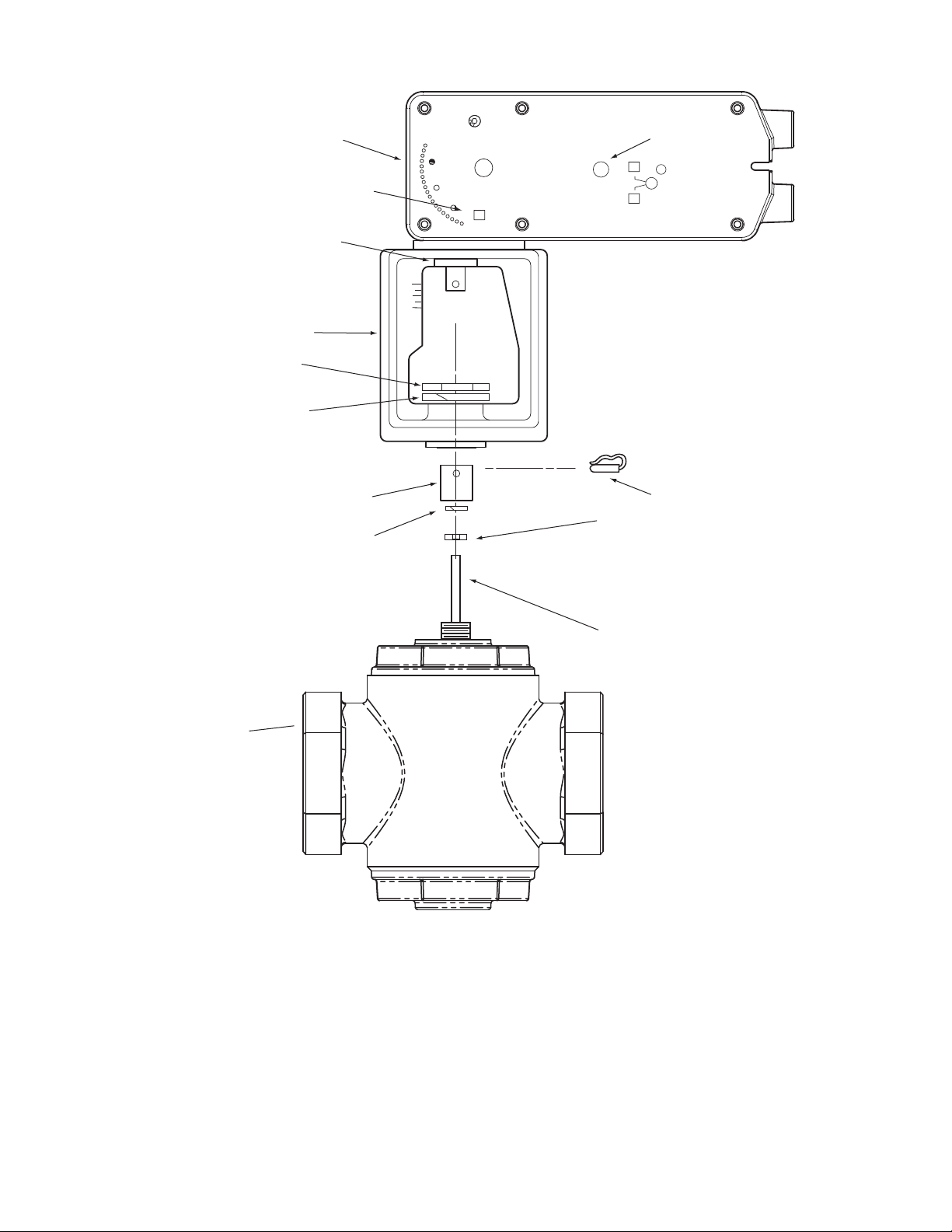
Linear Actuator
Mounting Bracket
Stem Extension
Hex Mounting Nut
Valve Body
(small)
a
Manual Override
L
L
Rack
b
Lock Washer
Jam Nut
a
R
Set Screw
b
b
Valve Stem
b
Connecting Pin
a
a Not included with linear actuator.
b AM-731 parts
b
Figure-1 AM-731 Kit with MX51-720X Actuator, Exploded View.
2 Copyright 2010 Schneider Electric All Rights Reserved. F-27203-3
Page 3

.
*Not included with linear actuator.
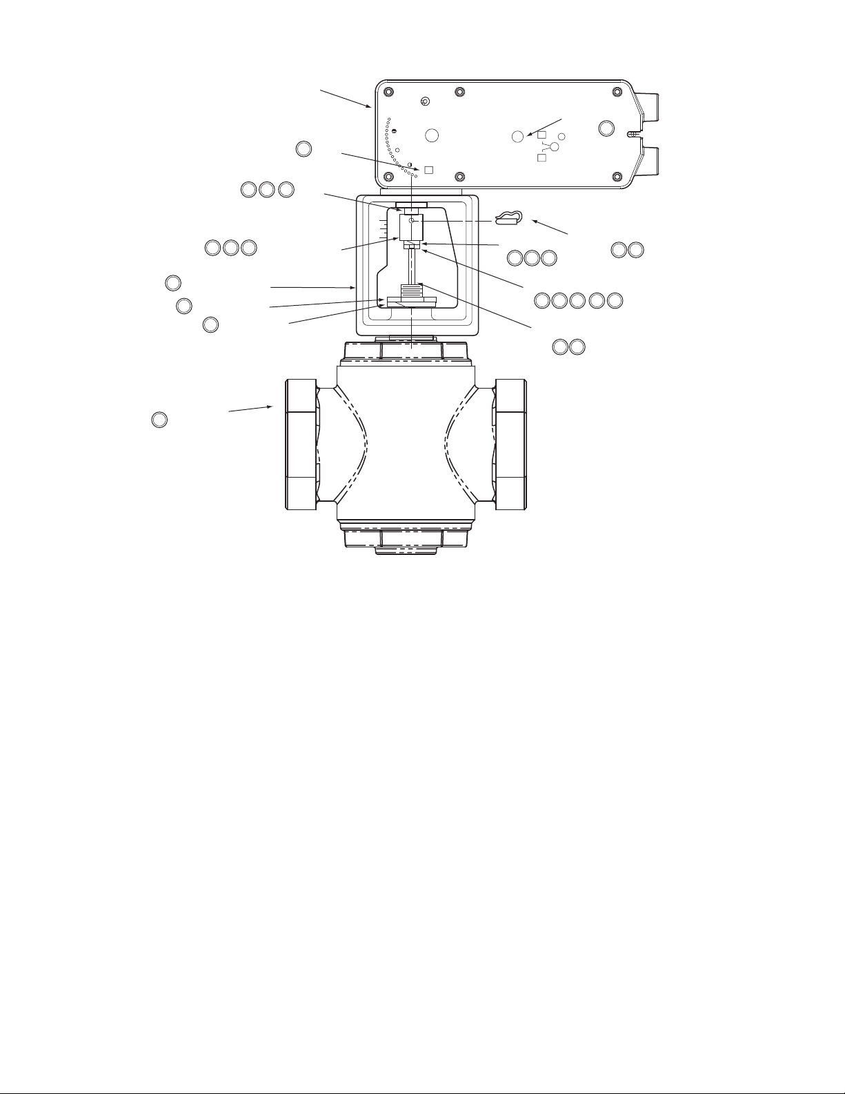
Valve Body*
Hex Mounting Nut*
Stem Extension
Mounting Bracket
Rack
Linear Actuator
Manual Override
Connecting Pin
Jam Nut
Valve Stem*
1
7
74
2
7
6
74
6
6
6
R
L
L
Lock Washer
4
9
Set Screw
8
4
4
5
Label
3
4
Figure-2 Typical Assembly and Installation of AM-731 Linkage Kit with MX51 Series Actuator to 1-1/4" to 2"
VB-7XXX Series Valve Bodies, Stem-Up Closed or Open, 2-Way and 3-Way Valves.
Installation: AM-731 linkage kit with MX51-720X Series Actuator to 1-1/4" to
2
" VB-7XXX Series Valve Bodies, Stem-Up Closed or Open, 2-Way and 3-Way
A. Install the actuator onto the valve. Set up the assembly according to the numbered steps
in Figure-2.
1. Locate the jam nut that came packaged with the kit.
2. Screw the jam nut onto the valve stem all the way as far as it will go. You may need to use a 5/16" (TOOL-20-1) open-end wrench. At least 1/2" of the valve stem should extend above the nut.
3. Place lock washer over valve stem.
4. Thread the stem extension onto the valve stem, making contact with the lock washer and jam nut.
5. Ensure 15o or 1-1/2 turns of manual override for actuator preload (Figure-12).
6. Orient the actuator mounting bracket on the valve and tighten the hex mounting nut securely against the bracket using TOOL-37. Raise the valve stem to the full up position.
7. Rotate stem extension until the through hole lines up with the through hole of actuator rack. Insert connecting pin to secure stem extension and tighten jam nut against stem extension using 5/16" (TOOL-20-1) open end wrench.
8. Affix open/closed label to the indicator in the appropriate position.
9. Insert set screw packaged with actuator into the most accessible side. Tighten with a size 10 IP Torx Plus bit to 20-25 lb-in (2.3-2.8 N-m).
B. Apply power to the actuator and check the system operation for heating or cooling output
in response to the control signal.
F-27203-3 Copyright 2010 Schneider Electric All Rights Reserved. 3
Page 4
Valve Body
Lock Washer
Stem Extension
(large)
Mounting Bracket
Rack
Linear Actuator
a Not included with linear actuator.
b AM-732 parts - included with actuator.
Manual Override
Connecting Pin
Jam Nut
Valve Stem
R
L
L
a
a
b
b
b
b
Lock Washer
b
Spanner Nut
a
Label
Figure-3 AM-732 with MX61-720X Actuator, Exploded View.
4 Copyright 2010 Schneider Electric All Rights Reserved. F-27203-3
Page 5
Linear Actuator
7
4
3
6
Rack
Label
Manual Override
L
R
L
4
Connecting Pin
4
32
1
Valve Stem*
43
63
6
4
*Not included with linear actuator.
5
Mounting Bracket
Spanner Nut*
5
Valve Body*
5
3
Lock Washer
5
64
Stem Extension
Lock Washer
32
Jam Nut
Figure-4 Typical Assembly and Installation of AM-732 Linkage Kit with MX61 Series Actuator to 2-1/2" to 4"
VB-9XXX Series Valve Bodies, Stem-Up Closed, 2-Way and 3-Way.
Installation: AM-732 linkage kit to MX61-720X Series Actuator to 2-1/2" to 4" VB-9XXX Series Valve Bodies, Stem-Up Closed, 2-Way and 3-Way
A. Install the actuator onto the valve. Set up the assembly according to the numbered steps
in Figure-4.
1. Locate the jam nut that came packaged with the kit.
2. Screw the jam nut onto the valve stem all the way as far as it will go (you may need to use a 3/4" open-end wrench). At least 1/2" of the valve stem should extend above the nut. Place the lock washer over the valve stem.
3. Thread the stem extension onto the valve stem, making contact with the lock washer and jam nut.
4. Ensure 15o or 1-1/2 turns of manual override for actuator preload (Figure-12).
5. Orient the actuator mounting bracket on the valve, place lock washer over valve stem and tighten the mounting nut securely against the bracket using 1-1/2" - 3" adjustable spanner wrench. Raise the valve stem to the full up position.
6. Rotate stem extension until the through hole lines up with the through hole of actuator rack. Insert connecting pin to secure stem extension and tighten jam nut against stem extension using 3/4” open end wrench.
7. Affix open/close label to the indicator in the appropriate position.
B. Apply power to the actuator and check the system operation for heating or cooling output
in response to the control signal.
F-27203-3 Copyright 2010 Schneider Electric All Rights Reserved. 5
Page 6

Valve Body*
Spanner Nut*
Stem Extension
Mounting Bracket
Rack
Linear Actuator
6
4
63
4
5
*Not included with linear actuator.
Manual Override
Connecting Pin
Jam Nut
Valve Stem*
1
3
3
5
R
L
L
43
Lock Washer
4
2
6
Lock Washer
2
7
2
Label
5
Figure-5 Typical Assembly and Installation of AM-732 Linkage Kit with MX61 Series
Actuator to 2-1/2" to 4" VB-9XXX Series Valve Bodies, Stem-Up Open,
2-Way.
Installation: AM-732 linkage kit to MX61-720X Series Actuator to 2-1/2" to 4" VB-9XXX Series Valve Bodies, Stem-Up Open 2-Way
A. Install the actuator onto the valve. Set up the assembly according to the numbered steps
in Figure-5.
1. Locate the jam nut that came packaged with the kit.
2. Screw the jam nut onto the valve stem all the way as far as it will go (you may need to use a 3/4" open-end wrench). At least 1/2" of the valve stem should extend above the nut. Place the lock washer over the valve stem.
3. Thread the stem extension onto the valve stem, making contact with the lock washer and jam nut.
4. Orient the actuator mounting bracket on the valve, place lock washer over valve stem and tighten the mounting nut securely against the bracket using 1-1/2" - 3" adjustable spanner wrench.
5. Insert the hex wrench into manual override and crank to extend the actuator rack to
its fully extended position, back off 1-1/2 turn, and lock (Figure-12). Remove hex
wrench to prevent accidental spring return of the actuator. Ensure valve stem is
completely pushed down.
6. Rotate stem extension until the through hole lines up with the through hole of actuator rack. Insert connecting pin to secure the assembly. Tighten jam nut against stem extension using 3/4" open end wrench.
7. Affix open/closed label to the indicator in the appropriate position.
B. Apply power to the actuator and check the system operation for heating or cooling output
in response to the control signal.
6 Copyright 2010 Schneider Electric All Rights Reserved. F-27203-3
Page 7

Valve Body
Lock Washer
Stem Extension
Mounting Bracket
Rack
Linear Actuator
a Not included with linear actuator.
b AM-734 parts
Manual Override
Connecting Pin
Jam Nut
Valve Stem
S
M
M
a
a
b
b
b
b
Lock Washer
b
Mounting Nut
b
Label
(Obsolete 1-1/2 - 2"
VB-9XXX before date
code 9404)
Figure-6 AM-734 Kit with MX61-720X Actuator, Exploded View.
F-27203-3 Copyright 2010 Schneider Electric All Rights Reserved. 7
Page 8

Linear Actuator
6
6
Rack
7
Label
Manual Override
L
R
L
4
6
3
5
Mounting Bracket
Mounting Nut
5
Lock Washer
5
5
Valve Body*
Stem Extension
6
Lock Washer
Jam Nut
1
Valve Stem*
Connecting Pin
2
3
3
6
2
43
5
*Not included with linear actuator.
Figure-7 Typical Assembly and Installation of AM-734 Linkage Kit with MX61 Series Actuator of Obsolete 1-1/2" to 2"
VB-9XXX Series Valve Bodies, before date code 9404, Stem-Up Closed, 2-Way and 3-Way.
Installation: AM-734 linkage kit to MX61-720X Series Actuator to Obsolete
1-1/2
" to 2" VB-9XXX Series Valve Bodies, before date code 9404, Stem-Up
Closed, 2-Way and 3-Way
A. Install the actuator onto the valve. Set up the assembly according to the numbered steps
in Figure-7.
1. Locate the jam nut that came packaged with the kit. Do not re-use the brass jam nut from an existing valve.
2. Screw the jam nut onto the valve all the way as far as it will go (you may need to use a 5/16" open-end wrench). Place lock washer over valve stem.
3. Thread the stem extension onto the valve stem, making contact with the lock washer and jam nut.
4. Ensure 15 or 1-1/2 turns of manual override for actuator preload (Figure-12).
5. Orient the actuator mounting bracket on the valve placing the lock washer over the valve stem. Tighten the mounting nut securely against the bracket using 1-3/8" open end wrench. Raise the valve stem to the full up position.
6. Rotate the stem extension until the through hole lines up with the through hole of actuator rack. Insert connecting pin to secure stem extension and tighten jam nut against stem extension using 5/16" open end wrench.
7. Affix open/closed label to the indicator in the appropriate position.
B. Apply power to the actuator and check the system operation for heating or cooling output
in response to the control signal.
8 Copyright 2010 Schneider Electric All Rights Reserved. F-27203-3
Page 9

Valve Body*
Hex Mounting Nut
Stem Extension
Mounting Bracket
Rack
Linear Actuator
6
4
63
4
4
*Not included with linear actuator.
Manual Override
Connecting Pin
Jam Nut
Valve Stem*
1
3
3
5
R
L
L
43
Lock Washer
4
2
6
Lock Washer
2
7
2
Label
5
6
Figure-8 Typical Assembly and Installation of AM-734 Linkage Kit with MX61 Series
Actuator to Obsolete 1-1/2" to 2" VB-9XXX before date code 9404 Series Valve Bodies,
Stem-Up Open, 2-Way.
Installation: AM-734 linkage kit to MX61-720X Series Actuator to Obsolete
1-1/2
" to 2" VB-9XXX before date code 9404 Series Valve Bodies, Stem-Up
Open, 2-Way
A. Install the actuator onto the valve. Set up the assembly according to the numbered steps
in Figure-8.
1. Locate the jam nut that came packaged with the kit. Do not re-use the jam nut from an existing valve.
2. Screw the jam nut onto the valve stem all the way as far as it will go (you may need to use a 5/16" open-end wrench). Place the lock washer over the valve stem.
3. Thread the stem extension onto the valve stem, making contact with the lock washer and jam nut.
4. Orient the actuator mounting bracket on the valve, place lock washer over valve stem and tighten the mounting nut securely against the bracket using 1-3/8" open end wrench.
5. Insert the hex wrench into manual override and crank to extend the actuator rack to
its fully extended position, back off 1-1/2 turn, and lock (Figure-12). Remove hex
wrench to prevent accidental spring return of the actuator. Ensure valve stem is
completely pushed down.
6. Rotate stem extension until the through hole lines up with the through hole of actuator rack. Insert connecting pin to secure the assembly. Tighten jam nut against stem extension using 5/16" open end wrench.
7. Affix open/closed label to the indicator in the appropriate position.
B. Apply power to the actuator and check the system operation for heating or cooling output
in response to the control signal.
F-27203-3 Copyright 2010 Schneider Electric All Rights Reserved. 9
Page 10

Linear Actuator
Mounting Bracket
Label
(both sides)
Rack
Manual Override
L
R
L
Spanner Nut
Lock Washer
Lock Washer
Hex Mounting Nut
Valve Body
b
b
Lock Washer
Stem Extension
Rack Adapter
b
Jam Nut
Valve Adapter
Valve Stem
a
a
b
Connecting Pin
b
b
b
b
a
a Not included with actuator
b AM-733
b
Figure-9 AM-733 Kit with MX61-720X Actuator and Old Style VB-9XXX after
Date Code 9404.
10 Copyright 2010 Schneider Electric All Rights Reserved. F-27203-3
Page 11

Valve Body*
Bonnet Nut
Stem Extension
Mounting Bracket
Rack
Linear Actuator
7
5
7
2
5
*Not included with linear actuator.
Manual Override
Connecting Pin
Jam Nut
Valve Stem*
1
3
6
R
L
L
32
Lock Washer
5
5
Captive Nut*
Valve Adapter
Lock Washer
Rack Adapter
Lock Washer
3
3
4
4 7
2
4
5
8
7
7
7
Label
5
6
Figure-10 Typical Assembly and Installation of AM-733 Linkage Kit to MX61-720X Series
Actuator to Obsolete 1-1/2" to 2" Old Style VB-9XXX After Date Code 9404 Series Valve
Bodies, Stem-Up Closed, 2-Way and 3-Way.
Installation: AM-733 linkage kit to MX61-720X Series Actuator to Obsolete
1-1/2
" to 2" Old Style VB-9XXX After Date Code 9404 Series Valve Bodies, Stem-
Up Closed 2-Way and 3-Way
A. Install the actuator onto the valve. Set up the assembly according to the numbered steps
in Figure-10.
1. Locate the jam nut that came packaged with the kit. Do not re-use the brass jam nut from an existing valve.
2. Place valve adapter over valve stem and screw it onto the valves’ captive nut, as far as it will go and tighten using 1-1/2" and 1-5/8" open end wrenches.
3. Thread the rack adapter onto the valve stem, making contact with the lock washer and jam nut using 5/8" and 5/16" open end wrenches.
4. Use the lock washer and screw the stem extension into the rack adapter and tighten using 5/8" open end wrench.
5. Orient the actuator and mounting bracket on the valve placing the lock washer and bonnet nut onto the threads of the valve adapter. Tighten the bonnet nut using spanner wrench and 1-1/2" open end wrench.
6. Ensure 15 or 1-1/2 turns of manual override preload (Figure-12). Raise the valve
stem to the full up position.
7. Rotate the rack until the through hole of the stem extension lines up with the through hole of actuator rack. Insert connecting pin to secure the assembly. Tighten the jam nut against the rack adapter using 5/16" open end wrench.
8. Affix open/closed label to the indicator in the appropriate position.
B. Apply power to the actuator and check the system operation for heating or cooling output
in response to the control signal.
F-27203-3 Copyright 2010 Schneider Electric All Rights Reserved. 11
Page 12

Valve Body*
Bonnet Nut
Stem Extension
Mounting Bracket
Rack
Linear Actuator
8
5
8
2
5
*Not included with linear actuator.
Manual Override
Connecting Pin
Jam Nut
Valve Stem*
1
3
9
R
L
L
62
Lock Washer
5
5
Captive Nut*
Valve Adapter
Lock Washer
Rack Adapter
Lock Washer
3
3
4
4 7
2
4
5
10
8
7
9
Label
5
7
3
3
3
7
Figure-11 Typical Assembly and Installation of AM-733 Linkage Kit to MX61-720X Series
Actuator to Obsolete 1-1/2" to 2" Old Style VB-9XXX After Date Code 9404 Series Valve
Bodies, Stem-Up Open, 2-Way.
Installation: AM-733 linkage kit to MX61-720X Series Actuator to Obsolete
1-1/2
" to 2" Old Style VB-9XXX After Date Code 9404 Series Valve Bodies, Stem-
Up Open, 2-Way
A. Install the actuator onto the valve. Set up the assembly according to the numbered steps
in Figure-11.
1. Locate the jam nut that came packaged with the kit. Do not re-use the brass jam nut from an existing valve.
2. Place valve adapter over valve stem and screw it onto the valves’ captive nut, as far as it will go and tighten using 1-1/2" and 1-5/8" open end wrenches.
3. Thread the rack adapter onto the valve stem, making contact with the lock washer and jam nut using 5/8" and 5/16" open end wrenches.
4. Use the lock washer and screw the stem extension into the rack adapter and tighten using 5/8" open end wrench.
5. Orient the actuator and mounting bracket on the valve placing the lock washer and bonnet nut onto the threads of the valve adapter. Tighten the bonnet nut using spanner wrench and 1-1/2" open end wrench.
6. Ensure that the valve stem is completely pushed down.
7. Insert the hex wrench into manual override and crank to extend the actuator rack to its’ fully extended position. Back the crank off 1-1/2 turn and lock (Figure-12). Remove hex wrench to prevent accidental spring return of the actuator.
8. Rotate the stem extension until the through hole of the stem extension lines up with the through hole of actuator rack. Insert connecting pin to secure the assembly.
9. Unlock manual override by turning crank 1/2 turn in the direction of the arrow. Allow the actuator to return to full up position. Tighten the jam nut against the rack adapter using 5/16" open end wrench.
10.Affix open/closed label to the indicator in the appropriate position.
B. Apply power to the actuator and check the system operation for heating or cooling output
in response to the control signal.
12 Copyright 2010 Schneider Electric All Rights Reserved. F-27203-3
Page 13

R
L
LOCK
L
Unlock
R
L
LOCK
Insert the hex wrench fully
into the manual override
mechanism.
Unlock the manual override, using the
hex wrench. To do this, turn, then release.
the hex wrench approximately 5˚ (1/2 turn)
CW, to "jog" the mechanism and release the
manual override preset.
When finished, lock the
manual override by turning
the screwdriver CW (in the
direction of the arrow).
Manual Override Locking
Mechanism
Rotation Indicator
Triangle
When necessary, the manual override mechanism may be
used to reposition the actuator at
any point between -5˚ and 85˚. This mechanism is
accessible on both sides of the actuator and can be used
to ensure tight close-offs for valves.
When using the manual override mechanism:
• Fully engage the hex wrench in the manual
override before cranking.
• When operating the manual override, ensure
proper release by backing off 5˚ from the full
extended mechanical stop.
1
2
3
1
1
2
F-27203-3 Copyright 2010 Schneider Electric All Rights Reserved. 13
Caution:
• Only use manual override when the actuator drive motor is not powered.
• Engaging the manual override when the actuator is powered will cause damage to the
gears.
• Using power tools to adjust the override will cause damage to the gears.
• Avoid manually repositioning the actuator beyond its adjustable travel limit setting.
Figure-12 Manual Override.
Page 14

CHECKOUT
Figure-13 MX51-720X Spring Return Valve Actuator Dimensions.
THEORY OF OPERATION
MAINTENANCE
FIELD REPAIR
After the entire system has been installed and the actuator has been powered up, the
following check can be made for proper system operation. Check for correct operation of the
valve while actuator is being stroked.
1. Apply power to the actuator. Actuator and valve should be driven to their powered position as determined by the control signal.
2. Break power to the actuator. Actuator and valve should return to the spring return position.
The MA, MF and MS series actuators are directly mounted onto the valve without the use of
an additional linkage. They are equipped with true mechanical spring return operation for
reliable, positive close-off on valves. When power is applied, the actuator moves to its
powered position, at the same time tensing the spring return safety mechanism. When the
power is removed, the spring returns the actuator to its normal position. The spring return
system provides consistent close-off force to the valve.
Regular maintenance of the total system is recommended to assure sustained optimum
performance. The Linear series actuators are maintenance free.
None. For replacement contact your Schneider Electric Representative and specify the
desired model number from Table 1.
DIMENSIONAL DATA
7
(178)
4
(103)
10-9/16 (268)
2-33/64
(64)
R
L
LOCK
R
Dimensions shown
are in inches (mm).
9-1/4 (235)
Minimum clearance: 5" for actuator removal.
14 Copyright 2010 Schneider Electric All Rights Reserved. F-27203-3
Page 15

1/2
Figure-14 MX61-720X Spring Return Valve Actuator Dimensions.
(13)
10-9/16 (268)
2-33/64
(64)
9-1/2
(241)
4
(103)
R
L
LOCK
R
Dimensions shown
are in inches (mm).
9-1/4 (235)
Minimum clearance: 5" for actuator removal.
F-27203-3 Copyright 2010 Schneider Electric All Rights Reserved. 15
Page 16

On
October 1st, 2009, TAC became the Buildings business of its parent company Schneider Electric. This document reflects the visual identity of Schneider Electric,
however there remains references to TAC as a corporate brand in the body copy. As each document is updated, the body copy will be changed to reflect appropriate
corporate brand changes.
Copyright 2010, Schneider Electric
All brand names, trademarks and registered
trademarks are the property of their respective
owners. Information contained within this
document is subject to change without notice.
F-27203-3
 Loading...