

Page 1
Installation Instructions
AM-674/75, AM-714
SmartX Actuator Weather Shield Base Mounting Plate
Applications
The AM-674 and the AM-714 weather shields provide moderate
weather protection for damper actuators which are mounted
outdoors. While these weather shields provide effective,
moderate, weather protection, they are not designed as a
water-tight enclosure.
The AM-675 base mounting plate is used with the AM-674 and
AM-714 weather shields if a suitable mounting surface for the
weather shield is not present.
Features
• Provides weather protection for Schneider Electric SmartX
actuators. See Model Chart.
Applicable Literature
• MX4X-7XXX and MX40-6XXX Series SmartX Actuator
Selection Guide, F-26646
• Cross-Reference Guide, F-23638
• MA4X-7XX3, MA4X-7XX3-50X, MA4X-7XXX, MA4X-7XXX-
50X Spring Return Two-Position SmartX Actuators General
Instructions,
F-26642
• MF4X-7XX3, MF4X-7XX3-50X Spring Return Floating SmartX
Actuator General Instructions, F-26644
• MS4X-7XX3, MS4X-7XX3-50X Spring Return Proportional
SmartX Actuator General Instructions, F-26645
• MA40-717X Spring Return Direct Coupled SmartX Actuator
General Instructions, F-26742
• MF40-6083, MF40-6153 Non-Spring Return Direct Coupled
SmartX Actuator General Instructions, F-26743
• MF40-6343 Non-Spring Return Direct Coupled SmartX
Actuator General Instructions,
F-26744
• MS40-634X SmartX Series Non-Spring Return Direct
Coupled Actuator General Instructions, F-26745
• MS40-6083, MF40-6153 SmartX Series Non-Spring Return
Direct Coupled Actuator General Instructions, F-26747
• MS40-717X SmartX Series Spring Return Direct Coupled
Actuator General Instructions, F-26748
• MF40-7173 SmartX Series Spring Return Direct Coupled
Actuator General Instructions, F-26749
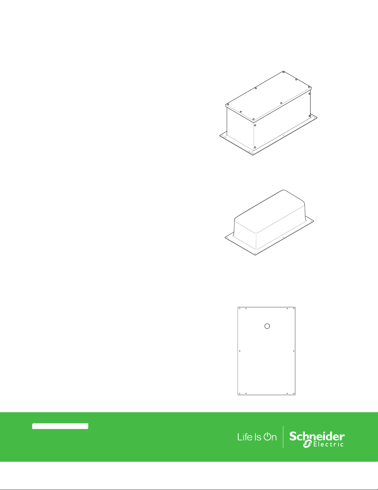
AM-674
AM-714
AM-675
© 2017 Schneider Elec tric. A ll righ ts rese rve d. All tr ademar ks are ow ned by Schneider Elect ric Industri es SAS or its af filiat ed companies. Novemb er 15, 2017 10:15 AM tc
Docume nt Number: F-25 097-6
Page 2

Table-1 Model Chart
Model Description For Use With
MA40-704X, MF40-7043, MS40-7043,
MA4X-707X, MF4X-7073, MS4X-7073,
AM-674 Weather Shield
AM-675 Base Mounting Plate AM-674, AM-714
AM-714 Weather Shield
MA4X-715X, MF4X-7153, MS4X-7153,
MA40-717X, MF40-7173, MS40-7173,
MF40-6083, MS40-6083, MF40-6153,
MS40-6153, MF40-6343, MS40-634X
MA40-704X, MF40-7043, MS40-7043,
MA4X-707X, MF4X-7073, MS4X-7073,
MA4X-715X, MF4X-7153, MS4X-7153,
MF40-6083, MS40-6083, MF40-6153,
Specifications
Material:
AM-674, 16 GA Galvanized Steel
AM-675, 12 GA Galvanized Steel
AM-714, Smoke-tinted Polycarbonate
Installation
Inspection
Inspect the package for damage. If damaged, notify the appropriate carrier immediately.
If undamaged, open the package and inspect the device for obvious damage.
Return damaged products.
Requirements
Installation Instructions
MS40-6153
Mounting
Tools (not provided):
— Appropriate screwdriver for the mounting screws used on the weather shield and the base
mounting plate
• Training: Installer must be a qualified, experienced technician.
• #8 sheet metal screws (not provided)
• No. 24 drill bit for #8 sheet metal screws
• Other accessories as appropriate
• Wiring diagrams for the applicable hardware
Mount the weather shield and base mounting plate onto the damper actuator as follows:
1. The weather shield must be mounted onto a flat, rigid surface that is at least as large as the
base of the weather shield. If the actuator mounting surface does not meet this requirement,
mount the optional AM-675 base mounting plate before mounting the damper actuator and
weather shield, as follows:
a. Evaluate the mounting surface to define the number and locations of mounting holes for
the base mounting plate.
b. Mark the mounting hole locations on the base mounting plate (See Figure-3). Drill the
mounting holes at the marked locations.
c. Position the base mounting plate on the mounting surface. Transfer the mounting hole
locations from the base mounting plate to the mounting surface.
d. Drill the holes at the transferred locations in the mounting surface. Secure the base
mounting plate to the mounting surface, using the supplied screws.
November 15, 2017 10:15 AM tc © 2017 Schneider Elec tric. A ll righ ts rese rve d. All tr ademar ks are ow ned by Schneider Elect ric Industri es SAS or its af filiat ed companies.
Document Number: F-25097-6
Page 3

Installation Instructions
3. Shorten both ends of the damper actuator’s anti-rotation mounting bracket, if necessary to fit
inside weather shield, by cutting it at each end (See Figure-1). Mount the damper actuator
onto the base mounting plate. Install any accessories onto the actuator, as applicable.
Actuator anti-rotation
Mounting Bracket
Cut
Bracket
Here
(if necessary to fit inside
weather shield)
Figure-1 Shortening the Actuator Mounting Bracket.
4. Assemble the weather shield as follows:
Note:
The AM‑674 weather shield is supplied disassembled. This allows the following options: to
assemble the shield completely so as to totally conceal the damper actuator, or to assemble it
partially, leaving the bottom open to provide easy access to the actuator.
a. Assemble the ends and sides, omitting a side or end as desired, to allow easy access to
the actuator.
b. If the base mounting plate is not used, position the weather shield on the mounting
surface. Transfer the mounting hole locations from the weather shield to the mounting
surface (See Figure-3). Drill the holes at the transferred locations in the mounting surface.
Caution:
When applying the foam gasket, take care that the gasket is not stretched and that the
surface is clean and dry. Stretching the gasket may cause it to shrink and loosen with age.
c. A foam gasket is supplied with the weather shield. It may be installed to provide a bet ter
seal between the weather shield and its mounting surface, or between the cover and the
sides of the weather shield. If the foam gasket is to be used on the cover, peel the backing
from the gasket, then apply the gasket onto the inside mounting surface of the cover. If the
foam gasket is to be used between the weather shield and its mount ing surface, peel the
backing from the gasket, then apply the gasket onto the mounting flange of the weather
shield.
d. If a more weather-tight installation is desired, apply a silicon sealer on all the inside seams
of the weather shield.
e. Install the weather shield onto the mounting surface or the base mounting plate, if used.
© 2017 Schneider Elec tric. A ll righ ts rese rve d. All tr ademar ks are ow ned by Schneider Elect ric Industri es SAS or its af filiat ed companies. Novemb er 15, 2017 10:15 AM tc
Docume nt Number: F-25 097-6
Page 4

Maintenance
Field Repair
Dimensional Data
Installation Instructions
The weather shield and base mounting plate require no maintenance.
Regular maintenance of the total system is recommended to assure sustained, optimum
performance.
Visually inspect the AM‑714 for moisture build‑up inside the shield.
None. Replace any damaged or failed components with functional replacements.
See Figure‑2 for dimensional data for Weather Shield AM‑674.
See Figure‑3 for dimensional data for Base Mounting Plate AM‑675.
See Figure‑4 for dimensional data for Weather Shield AM‑714.
13”
(330.2 mm)
14 3/8”
(365.1 mm)
3/16” (4.8 mm) diameter
10 holes
8”
(203.2 mm)
6”
(152.4 mm)
9 1/2”
(241.3 mm)
Figure-2 Dimensions of Weather Shield AM-674.
November 15, 2017 10:15 AM tc © 2017 Schneider Elec tric. A ll righ ts rese rve d. All tr ademar ks are ow ned by Schneider Elect ric Industri es SAS or its af filiat ed companies.
Document Number: F-25097-6
Page 5

Installation Instructions
4"
(102 mm)
5 1/4"
(146 mm)
12 3/4" (324 mm)
16" (406 mm)
8 3/8"
(213 mm)
3/16" dia. (4.8 mm)
6 holes
7/8" dia.
(22.2 mm)
2 holes
3/16” (4.8 mm) diameter
10 holes
13/16”
(20.6 mm)
diameter
14 5/16”
(363.5 mm)
4 21/32”
(118.3 mm)
3 5/32”
(80.2 mm)
9 5/16”
(236.5 mm)
Figure-3 Dimensions of Base Mounting Plate AM-675.
Figure-4 Dimensions of Weather Shield AM-714.
© 2017 Schneider Elec tric. A ll righ ts rese rve d. All tr ademar ks are ow ned by Schneider Elect ric Industri es SAS or its af filiat ed companies. Novemb er 15, 2017 10:15 AM tc
Docume nt Number: F-25 097-6
Page 6

Installation Instructions
November 15, 2017 10:15 AM tc © 2017 Schneider Elec tric. A ll righ ts rese rve d. All tr ademar ks are ow ned by Schneider Elect ric Industri es SAS or its af filiat ed companies.
Document Number: F-25097-6
 Loading...