

Page 1
Application
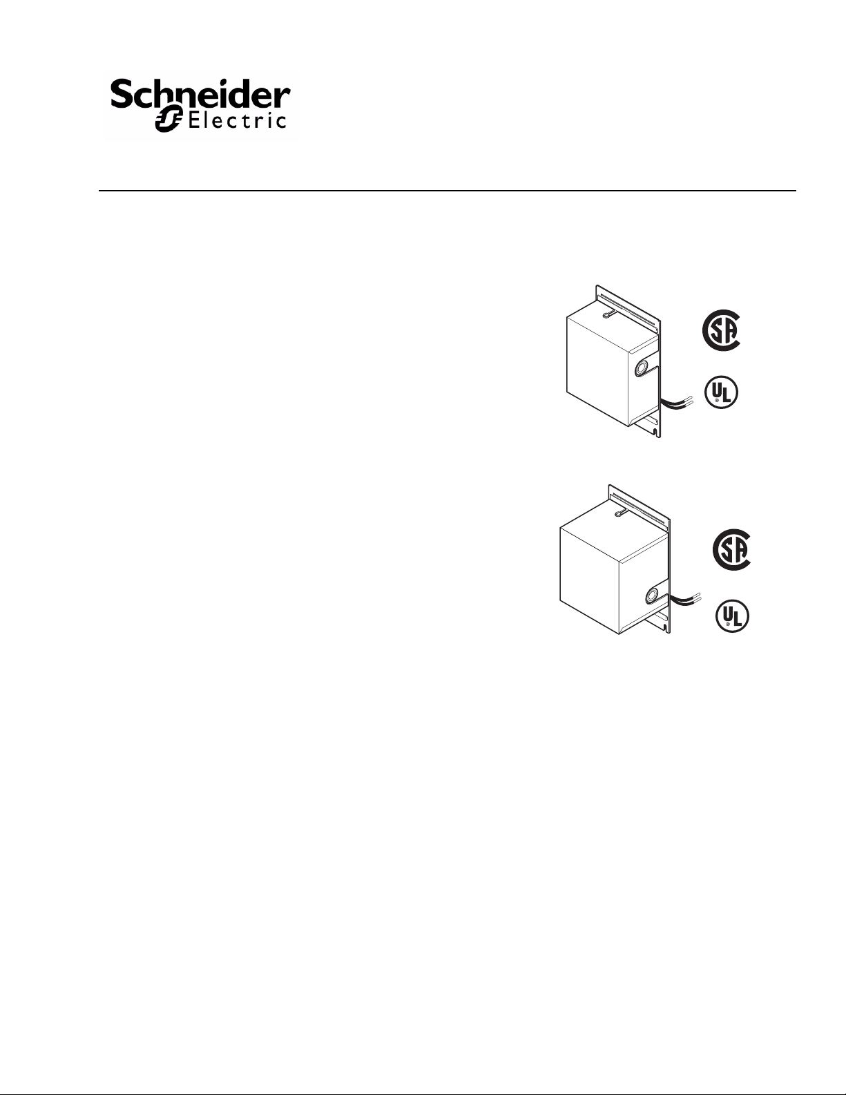
AM-321, AM-332
AM-341, AM-342
These actuator accessory kits are designed for
installation on MC, MF, MP, MU, and MUP type
oil-submerged gear train actuators. The accessory kits
are coupled to the rear of an actuator output shaft by
means of an interlocking drive disc.
Features
• Potentiometers provide accurate feedback of
actuator
position for indication and precision control
AM-321, AM-332
AM-341, AM-342
Accessory Kits
General Instructions
• Adjustable differential SPDT auxiliary switches may
be
adjusted to operate at any point in the actuator
stroke for maximum application flexibility
Applicable Literature
• Cross-Reference Guide, F-23638
• Reference Manual, F-12683
• Application Manual, F-21335
• Electric/Electronic Products Catalog, F-27382
• AM-348 Accessory Kit Mounting Bracket General
In
structions, F-10538
• MC-351, MC-421, MC-431, MC-4311 Three-Wire,
T
wo-Position Actuators General Instructions
F-
8366
• MP-3XX Series, MP-4XX Series, MP-2XXX Series,
an
d MP-4XXX Series Reversible and Proportio
Electr
ic Actuators General Instructions, F-15479
,
nal
Printed in U.S.A. 6/10 © Copyright 2010 Schneider Electric All Rights Reserved. F-09240-12
Page 2

SPECIFICATIONS
Outputs
Environment
Auxiliary Switch:
AM-321, 341, 342, Snap-action SPDT switches. AM-321 and AM-342 contain two auxil-
iary switches, and AM-341 contains four auxiliary switches. The setting of each switch is
adjustable, using the wrench included. The differential of each switch is adjustable, with
a minimum differential of 9°.
Potentiometer:
AM-332, 342, Spring-loaded, friction-driven copper wiper arm with a contact that rides on
a uniformly wound wire resistance card.
Resistance Card, Resistance of 100 Ω; use with a power supply not to exceed
25 Vac. Electrical capacity of 3 watts.
Connections: Coded screw terminals.
Mounting: To back of actuator, or AM-348.
Case: Aluminum. 1/2" conduit knockouts on right and left hand sides.
Ratings (All models except AM-332), Refer to Table-1.
Ambient Temperature Limits:
Shipping & Handling, -40 to 176° F (-40 to 80° C).
Operating, -22 to 122° F (-30 to 50° C).
Humidity: 5 to 80% relative humidity, non-condensing.
Table-1 Electrical Ratings for Access or y Kits with Electrical Switches.
Part
Number
AM-321
AM-341
AM-342
ACCESSORIES
None
TOOLS
Screwdriver to install the screws which secure the accessory kit to the actuator or mounting bracket.
Full Load Amps Locked Rotor Amps Non-Inductive Amps
120 Vac 240 Vac 120 Vac 240 Vac 120 Vac 240 Vac
5.8 2.9 34.8 17.4 15 7.5 2000 VA
Max.
Total
Load
Not to
Exceed
2 © Copyright 2010 Schneider Electric All Rights Reserved. F-09240-12
Page 3

INSTALLATION
W A R N I N G
C A U T I O N
C A U T I O N
Inspection
Requirements
Inspect the package for damage. If damaged, notify the approp riate carrier immediately.
If undamaged, open the package and inspect the device for obvious damage.
Return damaged products.
• Tools (not provided): Appropriate screwdriver for accessory kit mounting screws
• Training: Installer must be a qualified, experienced technician
• Appropriate accessories
• Wiring diagrams
• Disconnect the power supply (line power) before installation to prevent injury and equip-
ment damage.
• Make all connections in accordance with national and local electrical codes and the wir-
ing diagram.
• Use copper conductors only.
• Do not exceed the ratings of the device(s).
• Do not apply power to the unit unless the damper linkage and/or the valve assembly have
been installed.
• Avoid locations where excessive moisture, corrosive fumes, or vibration is present.
• Do not install insulation on any part of the actuator.
Mounting
The AM-321, AM-332, AM-341 and AM-342 accessory kits can be mounted onto the MC,
MF, MP, MU and MUP type oil-submerged gear train actuators.
To mount an accessory kit onto a nonspring-return actuator, proceed as follows:
1. Remove the actuator terminal cover and remove the four screws which secure the actuator back plate. Discard the back plate.
2. Remove the cover from the accessory kit.
3. Align, on the actuator, the back plate supplied with the accessory kit.
4. Align the interlocking drive discs on the accessory k
disc features one drive lug that is larger than the other, to ensure proper alignment.
Assemble the accessory kit to the actuator so that the drive discs are engaged. Secure
the accessory kit to the actuator with the four screws obtained when the actuator back
plate was removed.
5. Replace the cover onto the accessory kit.
To mount an accessory kit onto a spring-return actuator, proceed as follows:
1. Remove and discard the back plate which comes assembled to the accessory kit.
2. Remove the four external screws from the face of the actuator
Do not remove the screws which have anti-backup heads from the actuator. These
screws are used to secure the cover which retains the return spring in the casting.
it and the actuator. Note that each
’s spring-return housing.
3. Engage the drive discs on the accessory kit and the actuator. Note that each disc features one drive lug that is larger than the other
accessory base holes with those on the spring-return housing. Secure the accessory kit
to the housing with the four screws previously removed from the spring-return case.
F-09240-12 © Copyright 2010 Schneider Electric All Rights Reserved. 3
, to ensure proper alignment. Align the
Page 4

WIRING
AM-321, AM-341 and AM-342 accessory kits must be connected to Class 1 circuits unless
all circuits are powered from a Class 2 circuit. Make all electrical connections in accordance
with the job wiring diagram and in compliance with national and local electrical codes.
ADJUSTMENTS
Auxiliary Switch Adjustment
Accessory kits AM-321 and AM-342 each contain two SPDT, snap-acting auxiliary switches.
Accessory kit AM-341 contains four such switches. All switches are independently adjusted
to operate at any point in the actuator stroke. Large screw-type terminals, marked “C,” “B,”
and “R,” are provided for connections. The terminals marked “C” are common for each
SPDT switch, and those marked “B” and “R” are the contact terminals. On CW rotation of
the actuator, the “B” contact closes. On CCW rotation of the actuator, the “R” contact closes.
Refer to
auxiliary switch assembly.
Set the operating points of the auxiliary switches as follows:
1. With the accessory kit mounted onto the actuator , run the actuator CCW to the end of it s
2. Using a wrench, turn the black cam CW or the white cam CCW (as determined when
3. Turn the black cam CW until the depression in the cam is at the point on the scale where
4. If the minimum switch differential is required, the switch adjustment is now completed.
5. If a setting other than the minimum diff erentia l is required, turn the white cam CW until
6. Run the actuator through its entire travel to verify the switch settings.
Figure-1 for an internal view of an AM-342 accessory kit showing the features of an
travel. Refer to the diagram on the underside of the actuator cover and/or the actuator
instruction sheet.
viewing the actuator output shaft), until both cams move simultaneously. This provides
the minimum switch differential of approximately 9°.
the switch is to make “B” the upper contact. Both cams should move when the black
cam is turned.
its lobe is at the desired position on the scale, where the switch is to make “R” the lower
contact.
Auxiliary Switch
Terminal Screws
Potentiometer
Terminal Screw
Wiper Arm
Potentiometer
Slidewire
“E” Ring
Wiper Arm
Terminal Screw
Potentiometer Base
Auxiliary
Switch Assembly
Auxiliary
Switch Cams
Figure-1 Internal Features of AM-342 Accessory Kit.
4 © Copyright 2010 Schneider Electric All Rights Reserved. F-09240-12
Page 5

Potentiometer Adjustment
MAINTENANCE
Accessory kit AM-332 contains a potentiometer. This potentiometer consists of a
spring-loaded, friction-driven, copper wiper arm with a contact that rides on a uniformly
wound wire resistance card. The standard card has a resistance of 100 Ω, and is to be used
only with a power supply which does not exceed 25 Vac. The electrical capacity of the
resistance card is approximately 3 watts. For a view showing features of such a
potentiometer, refer to
Adjust the potentiometer as follows:
1. With the accessory kit mounted onto the actuator, run the actuator to the CCW end of its travel.
2. Manually position the wiper arm at the CCW end of the resistance card.
The accessory kits require no maintenance.
Regular maintenance of the total system is recommended to assure sustained,
optimum performance.
Figure-1 for the internal view of an AM-342 accessory kit.
FIELD REPAIR
None. Replace an inoperative accessory kit with a functional unit.
F-09240-12 © Copyright 2010 Schneider Electric All Rights Reserved. 5
Page 6

DIMENSIONAL DATA
1/4"
(6mm)
6-49/64"
(172mm)
4-3/16"
(106mm)
4"
(102mm)
3-7/16"
(87mm)
AM-341, AM-342
Figure-2 Dimensions of Accessory Kits
AM-321, AM-332, AM-341 and AM-342.
2"
(51mm)
AM-321, AM-332
6 © Copyright 2010 Schneider Electric All Rights Reserved. F-09240-12
Page 7

F-09240-12 © Copyright 2010 Schneider Electric All Rights Reserved. 7
Page 8

On October 1st, 2009, TAC be came the Buildi ngs busine ss of its parent com pany Schneider El ectric. Th is documen t r eflec ts the v is ual identi ty of Sch nei der Electri c,
however there r emains references to T AC as a corporate brand in the body copy. As each doc um ent is updated, the body copy wil l be ch anged to refl ect appropriate
corporate brand changes.
Copyright 2010, Schneider Electric
All brand names, trademarks and registered
trademarks are the property of their respective
owners. Information contained within this
document is subject to change without notice.
F-09240-12
 Loading...