

Page 1
Cleveland Controls
Model
Division of UniControl Inc.
AFS–222–112
AIR PRESSURE SENSING SWITCH WITH ADJUSTABLE SET POINT RANGE
APPLICATION
Model AFS-222-1 12 Air Pressure Sensing Switch is a general purpose proving
switch designed for HVAC and Energy
Management applications. It may be used
to sense positive, negative, or differential air pressure. The AFS-222-112 is
equipped with convenient barbed sample
line connectors that accept flexible tubing.
GENERAL DESCRIPTION &
OPERATION
The plated housing contains a diaphragm,
a calibration spring and a snap-acting
SPDT switch.The barbed sample line connections located on each side of the diaphragm accept flexible tubing.
An enclosure cover guards against accidental contact with the live switch terminal screws and the set point adjusting
screw. The enclosure cover will accept a
½" conduit connection.
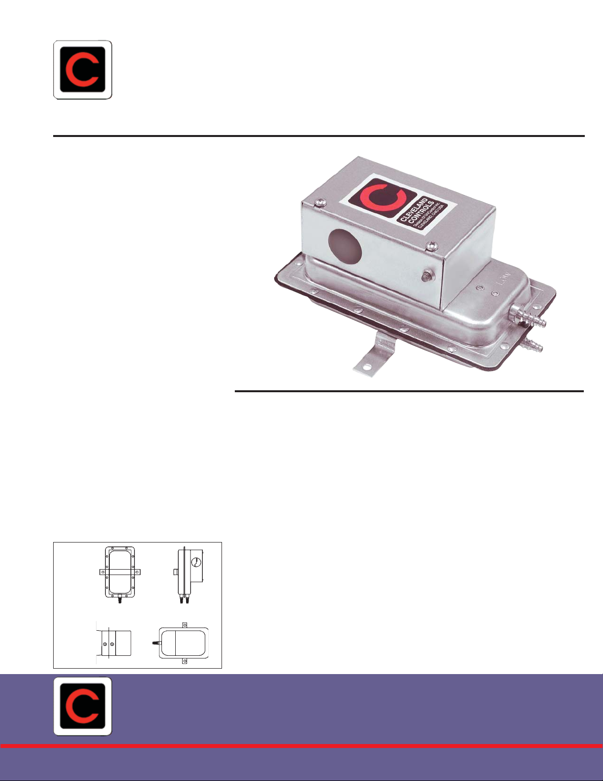
MOUNTING (SEE FIGURE 1)
AIR SAMPLING CONNECTION
(SEE FIGURE 2)
Select a mounting location which is free
from vibration. The AFS-222-112 must be
mounted with the diaphragm in any vertical plane in order to obtain the lowest
specified operating set point. Avoid
mounting with the sample line connections in the "up" position. Surface mount
via the two 3/16" diameter holes in the
(Figure 1)
Cleveland Controls
DIV
ISION OF UNICONTROL INC.
integral mounting bracket. The mounting
holes are 3-7/8" apart.
The AFS-222-112 is designed to accept
flexible tubing by means of barbed 1/4"
slip-on connections. For sample lines of
up to 10 feet, ¼” OD tubing is acceptable.
For lines up to 20 feet, use ¼” ID tubing.
For lines up to 60 feet, use ½” ID tubing.
Locate the sampling probe a minimum of
1.5 duct diameters downstream from the
air source. Install the sampling probe as
close to the center of the airstream as
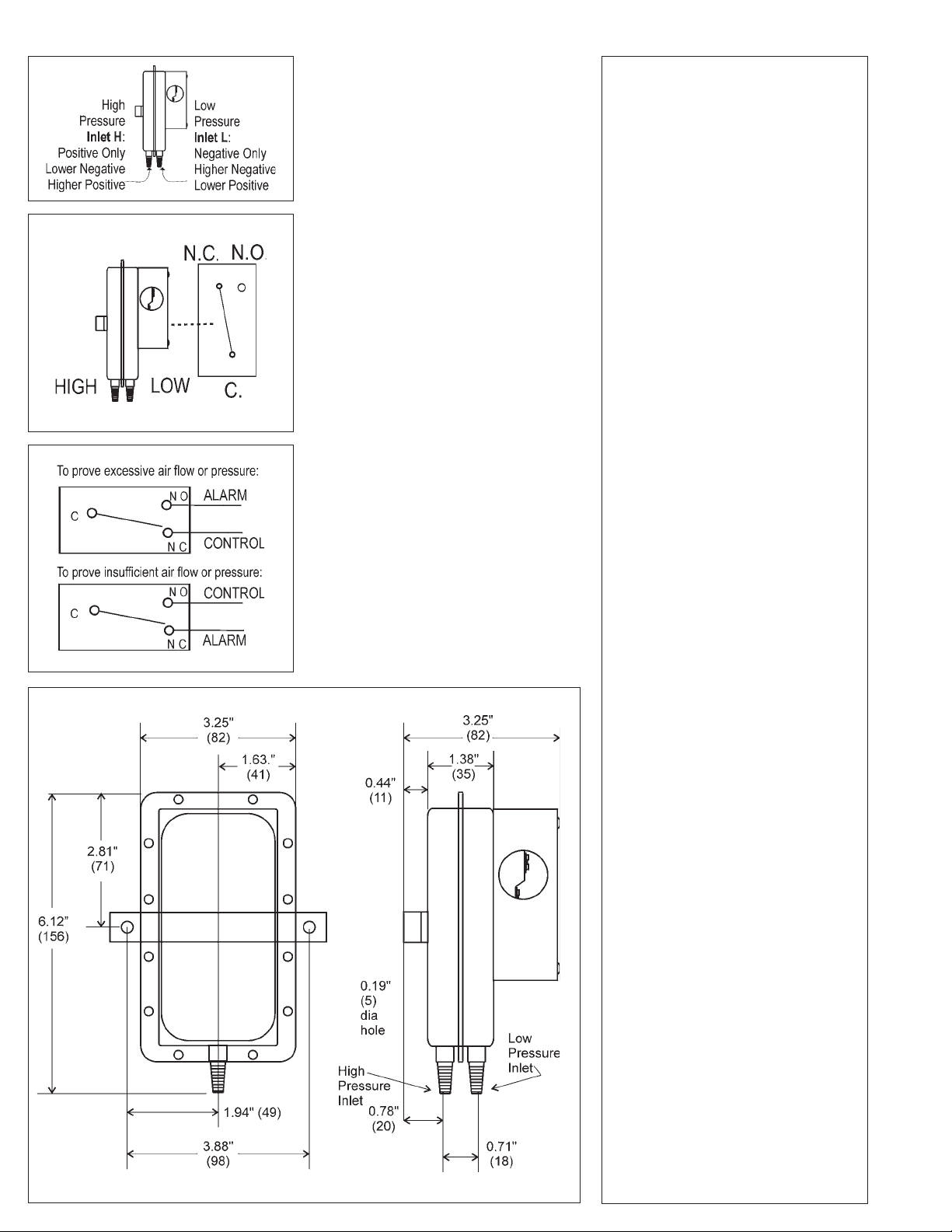
possible. Refer to Figure 2 to identify the
high pressure inlet (H) and the low pressure inlet (L). Connect the sample lines
as follows:
POSITIVE PRESSURE ONLY: Connect
the sample line to inlet H; inlet L remains
open to the atmosphere.
NEGATIVE PRESSURE ONLY: Connect
the sample line to inlet L; inlet H remains
open to the atmosphere.
TWO NEGA TIVE SAMPLES: Connect the
higher negative sample to inlet L. Connect the lower negative sample to inlet H.
TWO POSITIVE SAMPLES: Connect the
higher positive sample to inlet H. Connect
the lower positive sample to inlet L.
ONE POSITIVE AND ONE NEGATIVE
SAMPLE: Connect the positive sample to
inlet H. Connect the negative sample to
inlet L.
Bulletin AFS222-112.01
Page 2
(Figure 2)
(Figure 3)
(Figure 4)
ELECTRICAL
CONNECTIONS (SEE
FIGURE 3)
Before pressure is applied to the diaphragm, the switch contacts will be in the
normally closed (NC) position. The snap
switch has screw top terminals with cup
washers. Wire alarm and control applications as shown in Figure 4.
FIELD ADJUSTMENT
The adjustment range of an AFS-222-112
Air Switch is 0.05 ±.02" w.c. to 12.0" w .c.
To adjust the set point, t urn the adjusting screw counterclockwise until motion
has stopped. Next, turn the adjusting
screw 4 complete turns in a clockwise
direction to engage the spring. From this
point, the next ten turns will be used for
the actual calibration. Each full turn rep-
resents approximately 1.2" w.c.
Please note: T o properly calibrate an air
switch, a digital manometer or other measuring device should be used to confirm
the actual set point.
SPECIFICATIONS
MODEL AFS-222-1 12 AIR
PRESSURE SENSING
SWITCH WITH
ADJUSTABLE SET POINT
RANGE
Mounting Position: Mount with the
diaphragm in any vertical plane.
Set Point Range: 0.05 ± 0.02" w.c. to
12.0"w.c.
Field Adjustable “Operate Range”:
0.07"w.c. to 12.0" w.c.
Field Adjustable “Release Range”:
0.04"w.c. to 11.2" w.c.
Approximate Switching Differential:
Progressive, increasing from 0.02 ±
0.01"w.c. at minimum set point to
approximately 0.8 " w.c. at maximum
set point.
Measured Media: Air, or combustion
by-products that will not degrade
silicone.
Maximum Pressure: ½ psi (0.03 bar).
Operating Temperature Range:
-40F to 180F (-40 to 82C).
Life: 100,000 cycles minimum at 1/2
psi maximum pressure each cycle and
at maximum rated electrical load.
Electrical Rating:
300 VA pilot duty at 115 to 277 VAC,
15 amps noninductive to 277 VAC, 60
Hz.
Contact Arrangement: SPDT.
Electrical Connections: Screw-type
terminals with cup washers.
Conduit Opening: 7/8" diameter
opening accepts ½" conduit.
Sample Line Connectors: Two
barbed ¼" connectors will accept
flexible tubing.
Sample Line Connections: Two
barbed ¼" connectors will accept
flexible tubing.
Approval: UL, FM, CSA, CE
Shipping Weight: 1.2 lbs.
Accessories:
• Sample line probes.
• Orifice plugs (pulsation dampers).
Nominal Dimensions in Inches (Millimeters)
 Loading...