

Page 1
APPLICATION
The AEM-8120 series and AEM-8240 series transformers are
the only recommended transformers for use with the
CPM-8000 Series Controller, MPC-8000 Series Controller
and the ADM-8304 MPC-8000 Repeater. These transformers
provide low voltage power sources from 50 to 100 Va. Table
1 indicates the number of DLC modules that can be used with
each of the transformers.
SPECIFICATIONS
Ambient Temperature Limits:
Shipping and Storage, -40 to 140°F (-40 to 60°C) 10%
to 90% RH (non-condensing)
Operating, -40 to 135°F (-40 to 57°C) 10% to 90% RH
(non-condensing)
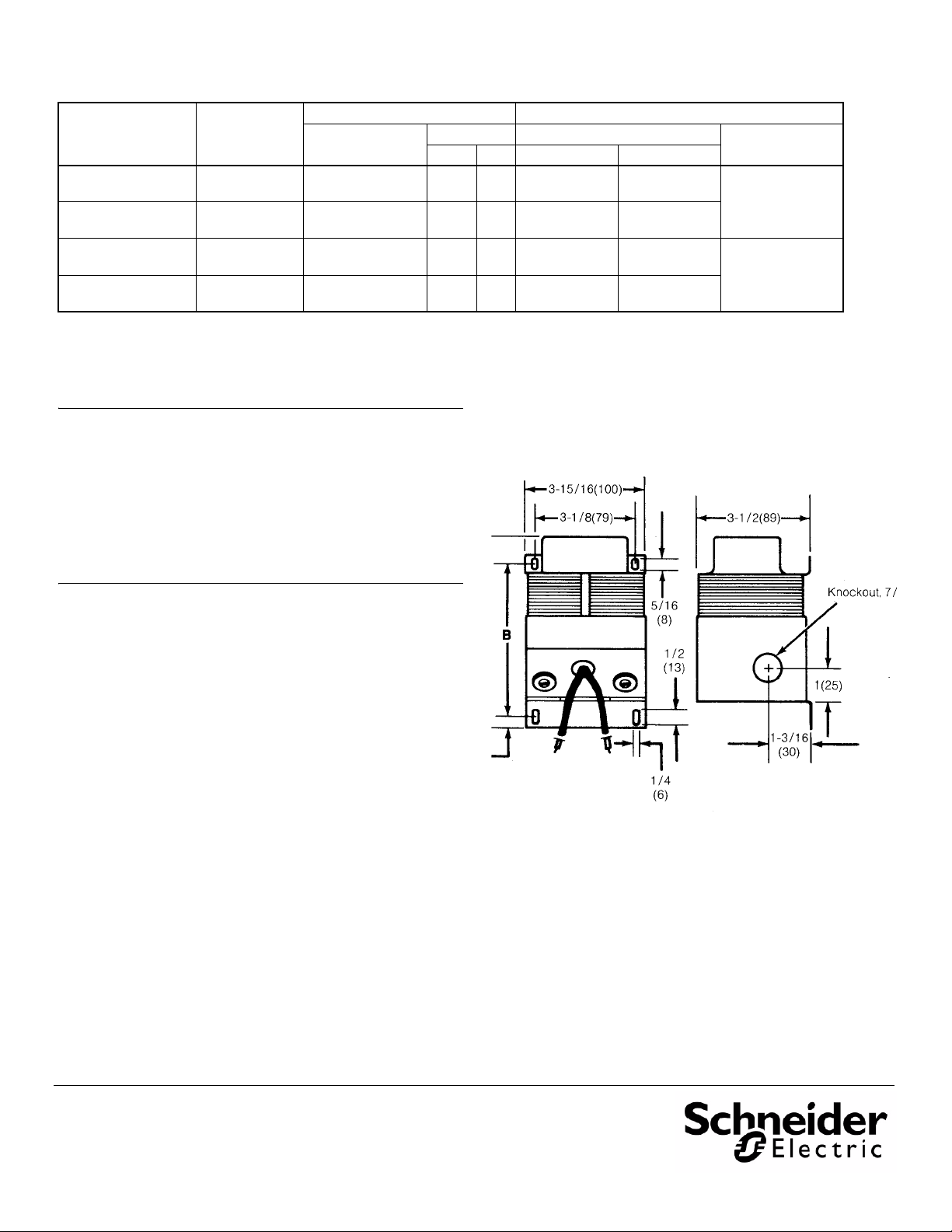
Dimensions: See Figure 1 and Table 1.
Mounting: On surface fre e of vibration.
Shipping Weight: See Table 1.
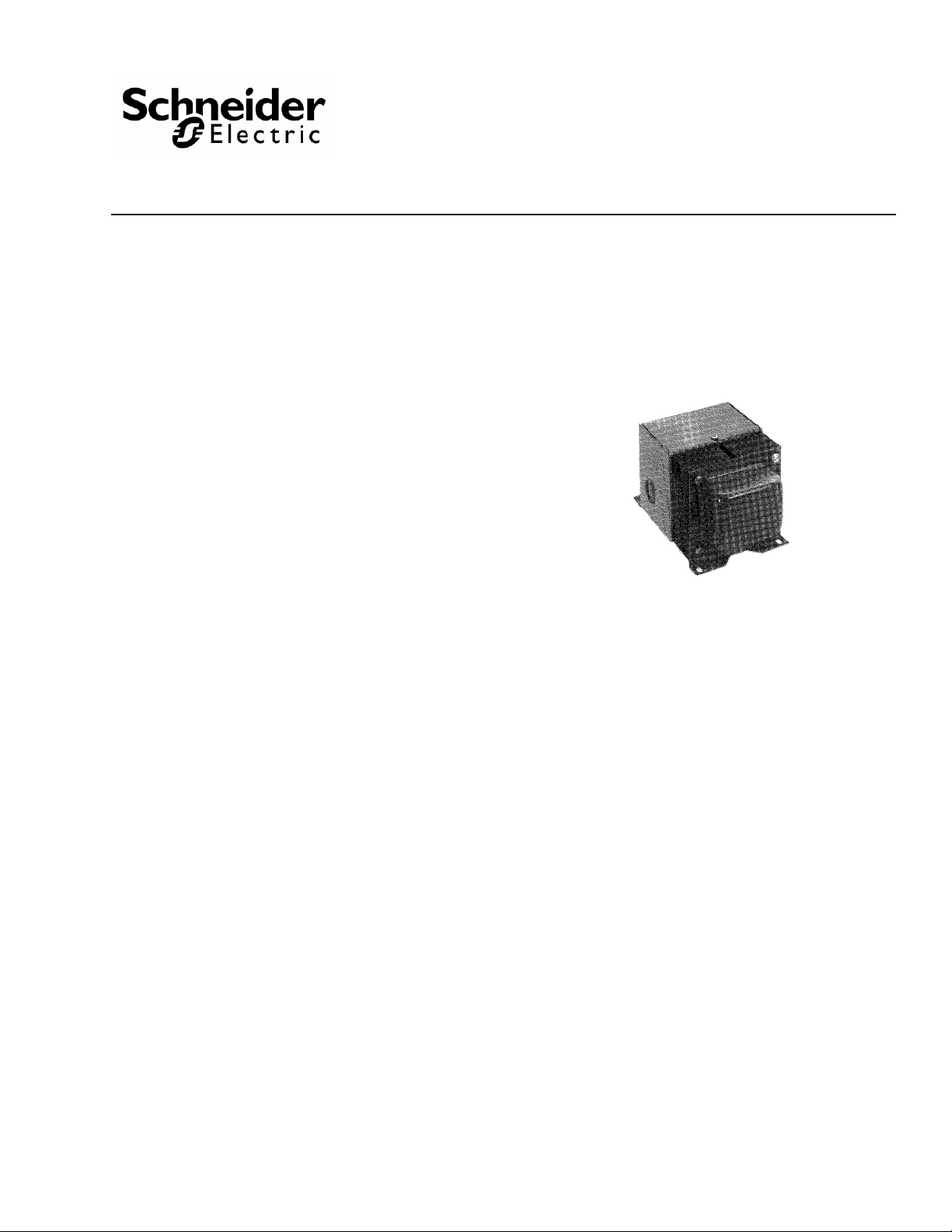
AEM-8120-005, AEM-8120-010
AEM-8240-005, AEM-8240-010
CPM 8000 HVAC Controller System
Transformers
General Instructions
OPTIONS
None
ACCESSORIES
None
PRE-INSTALLATION
Inspection
Visually inspect the carton for damage. If damaged, notify the
appropriate carrier immediately. If undamaged, Open the
carton and visually inspect the device for obvious defects.
Return damaged or defective products.
Required Installation Items
• Tools (not provided):
Volt-Ohm meter
Appropriate screwdriver for mounting screws
Appropriate drill and drill bit for mounting screws
• Wire nuts (not provided)
• Mounting screws (not provided)
Printed in U.S.A. 3/10 © Copyright 2010 Schneider Electric All Rights Reserved. F-21670-3
Page 2
On Octo ber 1s t, 2009, TA C became the Buildi ngs busi ness of its par ent com pany Sc hnei der Electric . This docum ent ref l ects the visual identity of Schneider Electric,
ho w ever t here remains ref er ences to TAC as a co rporate brand in the body copy. As eac h d oc um ent is updat ed, t he body co py wi ll be changed to r eflec t appropriate
Table-1
Part
Number
AEM-8120-005 1-20*
AEM-8240-005 1-20*
AEM-8120-010 21-40*
AEM-8240-010 21-40*
* Each ADM-8304 MPC-8000 Repeater counts as one module. Each CCM-8204 four output DO module counts as two modules. The total length of the DLC line, along with
the wire gauge, must also be considered when calculating the number of DLC modules that can be used with each transformer. Refer to the CPM and MPC wiring
in
structions for selection requirements.
No. of
Modules on
DLC Line
Primary Voltage
Electrical Physical
Secondary Dimensions
Volts VA A B
120
50/60 Hz
240
50/60 Hz
120
50/60 Hz
240
50/60 Hz
24 50 5-1/2 (140) 4-3/8 (111)
24 50 5-1/2 (140) 4-3/8 (111)
24 100 5-15/16 (151) 4-11/16 (119)
24 100 5-15/16 (151) 4-11/16 (119)
Shipping
Weight
4.6 lbs. (2.09 kg)
5.5 lbs. (2.5 kg)
INSTALLATION
Caution:
1. Installer must be a qualified, experienced technician.
2. Disconnect power supply before installation to prevent electrical shock and equipment damage.
3. Make all connections in accordance with the job wiring diagram, and in accordance with national and local electrical codes.
4. Do not exceed ratings of the device.
Mounting
Location: This transformer must be mounted on a vibration free
surface. Holes are provided on the base for surface mounting. The
transformer should be mounted in close proximity of the CPM/MPC
Controller or MPC-8000 Repeater (within 10 feet). For dimensions,
See Table 1 and Figure 1.
Wiring
A separate AEM series 24 Vac transformer must be provided for
each CPM-8000 Series Controller, each MPC-8000 Series
Controller and each ADM-8304 MPC-8000 Repeater. The
secondary of each transformer can only be connected to the CPM,
MPC or Repeater that it serves. The supply to the transformer
should be provided with a circuit breaker or disconnect (does not
have to be dedicated). Class 1 wiring must be used for the
transformer wiring. The primary voltages are 120 or 240 Vac.
Secondary voltage is 24 Vac. The enclosed connections are
pigtails for primary wiring, and the screw terminals are for
secondary wiring.
CALIBRATION
Not applicable.
Figure-1 Mounting Dimensions.
Checkout
If secondary voltage is not present, check the primary voltage as
shown in Table 1.
corpo r ate bra nd ch a nges.
Copyright 2010, Schneider Electric
All brand names, trademarks and registered
trademarks are the property of their respective
owners. Information contained within this
document is subject to change without notice.
F-21670-3
 Loading...