

Page 1
16:07-01
Issue 3 en
Electrical system in P, R, T series
Introduction and general
troubleshooting
©
Scania CV AB 2005, Sweden
Page 2

Contents
Introduction .................................................................................. 3
Electrical system in P, R and T
series
DEC system .................................................................................. 6
ECU system .................................................................................. 7
CAN network Overload on the CAN buses ................................... 12
.................................................................................. 4
Activation of the control unit..................................12
Vehicle internal time............................................... 13
ECU settings........................................................... 14
Cable harness.......................................................... 15
Power supply .......................................................... 16
Positive supply........................................................ 18
Moulded cables....................................................... 19
Earthing ..................................................................20
Connectors.............................................................. 24
User functions ................................................................................ 26
Wiring Diagrams ................................................................................ 28
Central electric unit ................................................................................ 34
Repairing cables ................................................................................ 35
Troubleshooting ................................................................................ 40
Communication problems on the
CAN buses
................................................................................ 55
Abbreviations ................................................................................67
©
2
Scania CV AB 2005, Sweden
16:07-01
Page 3

Introduction
The structure of the electrical system in P, R
and T series vehicles is described here in brief.
In comparison with previous series, the
electrical system is now made up to a greater
extent of a number of control units which
communicate with each other via a network.
This new platform for the electrical system
gives increased reliability and the ability to
more easily re-specify and troubleshoot the
electrical system.
A condition for being able to make use of the
benefits of the new network-based electrical
system is a knowledge of how the Scania
diagnostic tools should be used.
It is important to exercise care and accuracy
when handling connectors, cables and control
units, to ensure that system reliability is
maintained after troubleshooting and respecifying the vehicle.
Note: Always disconnect the battery earth lead
before doing any electric welding on the
vehicle. Connect the earthing cable of the
welding unit to the part to be welded, as close
to the welding area as possible. If the earthing
cable is connected in any other way, items such
as bearings or electronic components may be
damaged.
Note: Do not connect extra equipment to the
CAN cables. Overloading of these cables may
cause malfunctions.
16:07-01
©
Scania CV AB 2005, Sweden
3
Page 4
Electrical system in P, R and T series
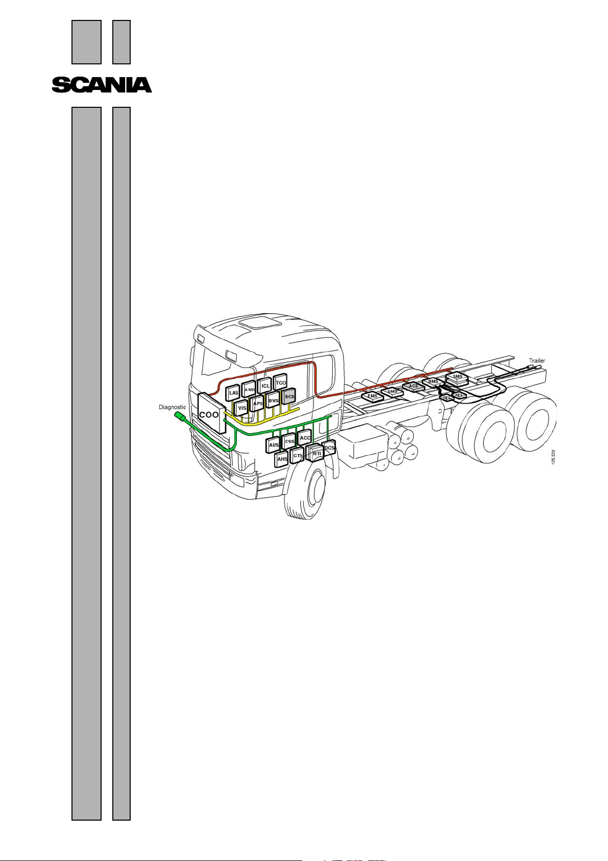
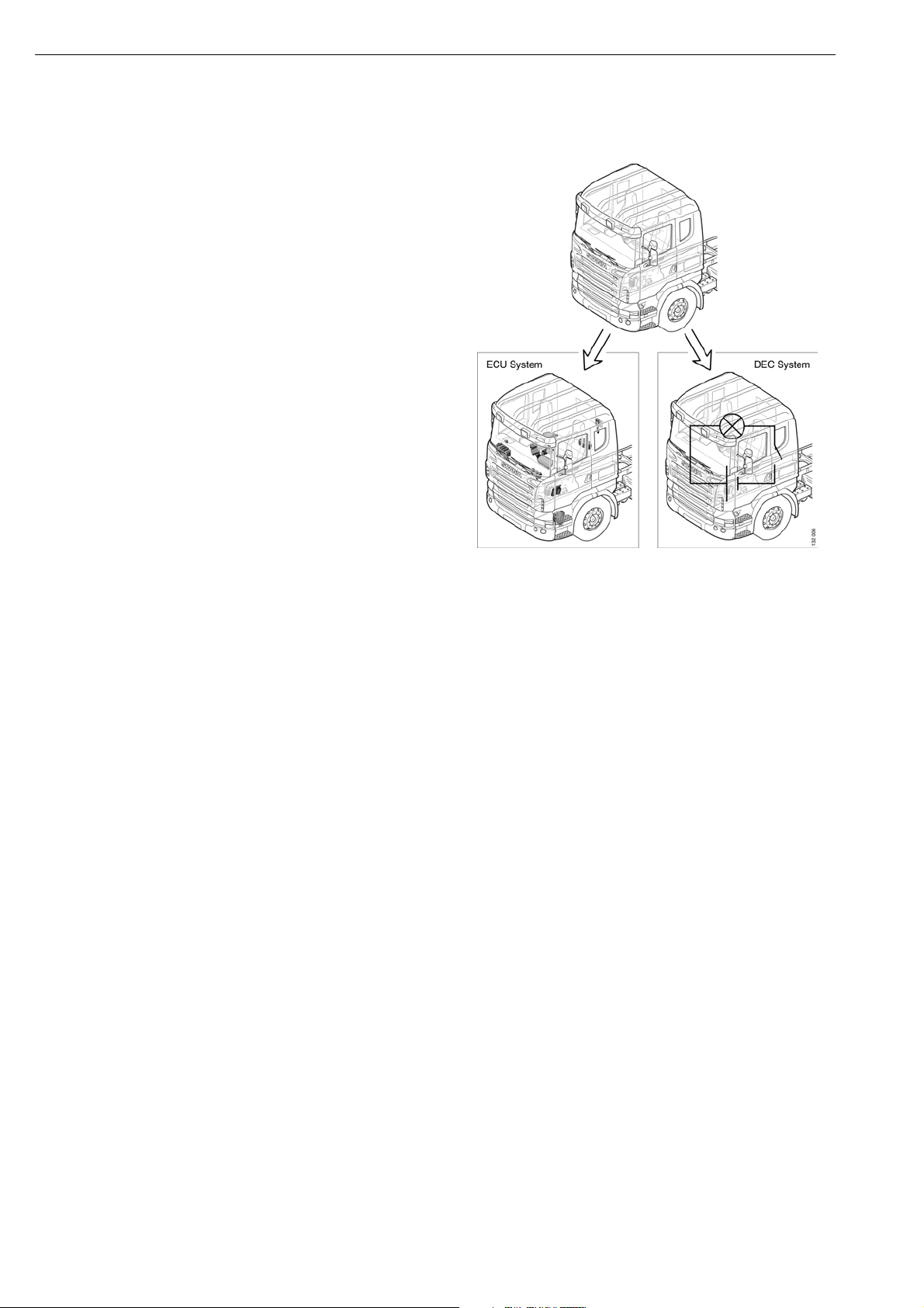
The electrical system on vehicles in the PRT
series has here been subdivided into the ECU
system (Electronic Control Unit) and the DEC
system (Discrete Electrical Circuit). The ECU
systems are controlled by an electronic control
unit, and they are connected to the CAN
network. The DEC systems can also be
controlled by an electronic control unit, but they
are not connected to the CAN network. Refer
also to Alternator and Starter motor in Multi and
the section on batteries in 16:06-41
©
4
Scania CV AB 2005, Sweden
16:07-01
Page 5
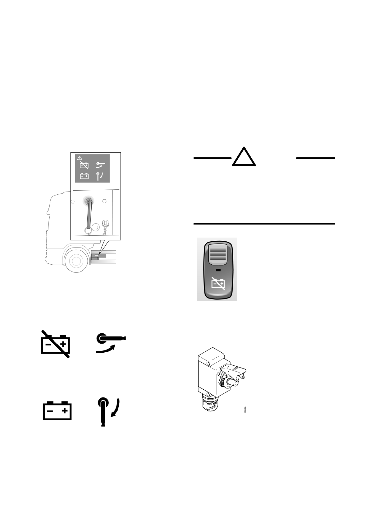
Battery master switch
The service switch is located by the battery box. Switch off the engine before disconnecting the
power. On vehicles with a safety switch the battery master switch is located on the instrument panel.
Some vehicles are also equipped with an exterior safety switch. When the battery master switch is
turned off, power is only supplied to the tachograph. Always disconnect the power in the vehicle
during servicing and work on the electrical system.
WARNING!
!
When the battery master switch cuts off
the power, the engine stops. The
vehicle becomes difficult to control if
this occurs when moving. Stop the
vehicle, if possible, before cutting off
the power.
The service switch is located by the battery
box. Switch off the engine before disconnecting
the power.
Service switch turned off.
Service switch turned on.
The safety switch for the battery master switch
is located on the instrument panel.
Exterior safety switch.
16:07-01
©
Scania CV AB 2005, Sweden
5
Page 6
DEC system
There are around thirty sub-systems which are
not connected to the CAN network. These
systems are a part of the DEC system group.
Examples of DEC systems are the kitchen
module, seat heating and window winders.
As the DEC system is not connected to the CAN
network, it is not possible to read any fault codes
from them using SDP3. All troubleshooting
should therefore be carried out in the normal
way using a multimeter.
©
6
Scania CV AB 2005, Sweden
16:07-01
Page 7

ECU system
units in the EBS system communicate through
an internal CAN.
The electronic control units in the ECU systems
are programmed to continuously write specific
messages to the CAN network. They are also
programmed to read specific messages which are
written by other control units.
One advantage of connecting together control units
in a network is that both the driver and the
mechanic can obtain significantly more
information on the vehicle status and on any faults.
This makes troubleshooting both simpler and
faster. This is provided you have access to the
Scania diagnosis and programming tool (SDP3).
Furthermore, it enables the mechanic to change
functions in the ECU systems in a simple way by
changing the settings in the control units with
SDP3. If you do not have access to SDP3,
however, it will be more difficult to troubleshoot
compared to earlier vehicle series.
The CAN network on a high specification PRT
series vehicle can contain around 20 ECU systems.
On the simplest vehicles, however, there are only
five ECU systems (EMS, COO, VIS, APS and
ICL).
It should be noted that ICL is connected to the
yellow CAN bus. Problems in this CAN bus
should not stop the vehicle. But if a problem
arises on the yellow CAN bus, this affects ICL
which is then unable to listen to the other CAN
buses and will then prompt the driver to stop
the vehicle.
Several ECU systems in the PRT series were
controlled by an ECU also in the 4-series, and they
were linked together in a CAN network. This
applied to: BMS, EMS, GMS and RTG. Other
systems were controlled by an ECU, but were not
linked together in a CAN network. This applies to:
the radio (now: AUS), the auxiliary heaters with
control unit (ATA/WTA with CTS), the alarm
system (LAS), the air suspension (SMS) and the
tachograph (TCO). Finally, some systems have
been introduced whose functions were previously
controlled using conventional technology such as
relays. This applies to: ACC, APS, BWS, ICL and
VIS.
To reduce the risk of the CAN bus being
overloaded with messages, Scania has chosen to
divide the ECU systems between three CAN buses.
The ECU systems which are most important to
vehicle operation (BMS, COO, EMS and GMS)
are linked together on a CAN bus (red bus). The
other ECU systems are subdivided onto two CAN
buses which Scania calls the yellow and green bus.
Scania Diagnos is connected to the green bus.
In addition to these CAN buses, there can be
additional CAN buses. For example, some of the
©
16:07-01
Scania CV AB 2005, Sweden
7
Page 8

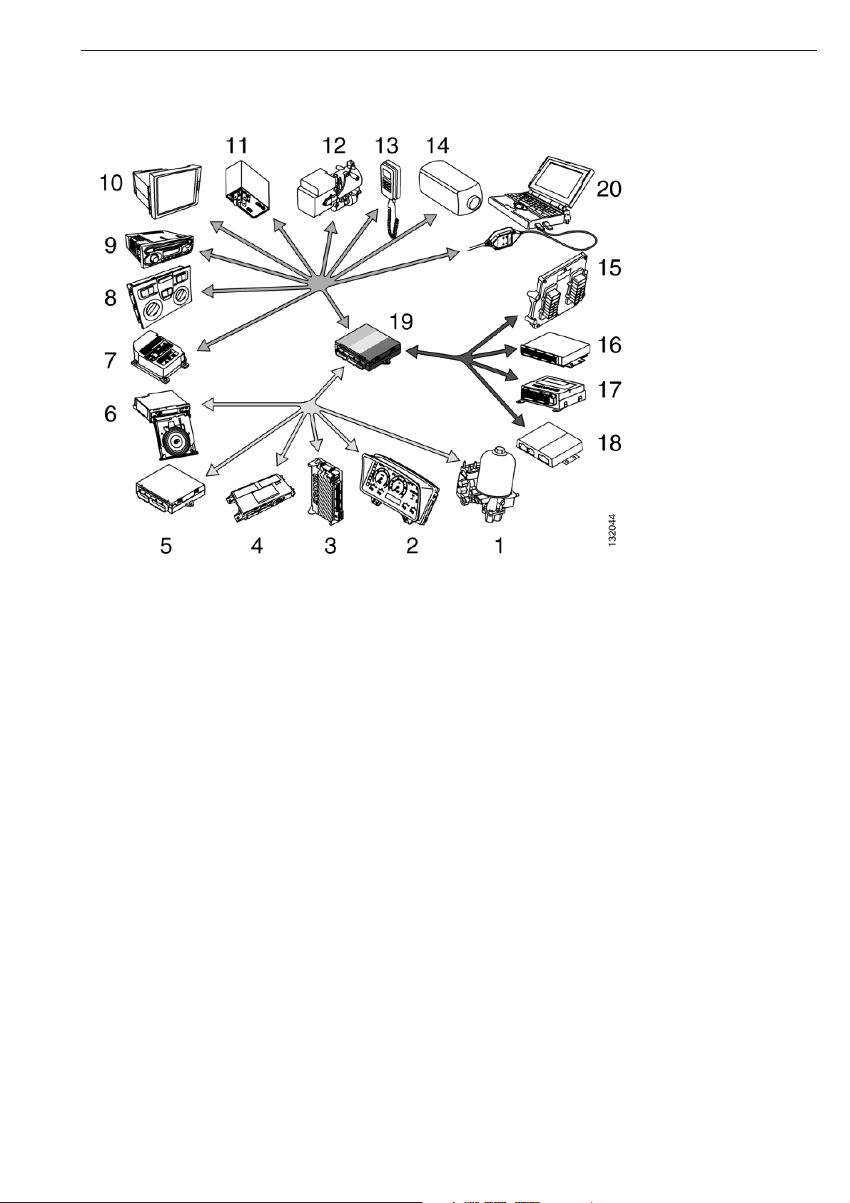
Example of functions in the CAN network
Function ECU designation CAN colour
1 Compressed air supply APS Yellow
2 Instrument cluster ICL Yellow
3 Lights, visibility and
VIS Yellow
horn control
4 Locks and alarm LAS Yellow
5 Bodywork interface BWS Yellow
6 Tachograph TCO Yellow
7 Crash safety, airbag CSS Green
8 Climate control ACC Green
9 Radio AUS Green
10 PC RTI Green
11 Vehicle data RTG Green
12,
Auxiliary heater with
13,
control panel
CTS. ATA. WTA Green
14
15 Engine management EMS Red
16 Brake BMS Red
17 Air suspension SMS Red
18 Gearbox and retarder
GMS Red
control
19 Coordinator COO Red
©
8
Scania CV AB 2005, Sweden
16:07-01
Page 9
16:07-01
©
Scania CV AB 2005, Sweden
9
Page 10
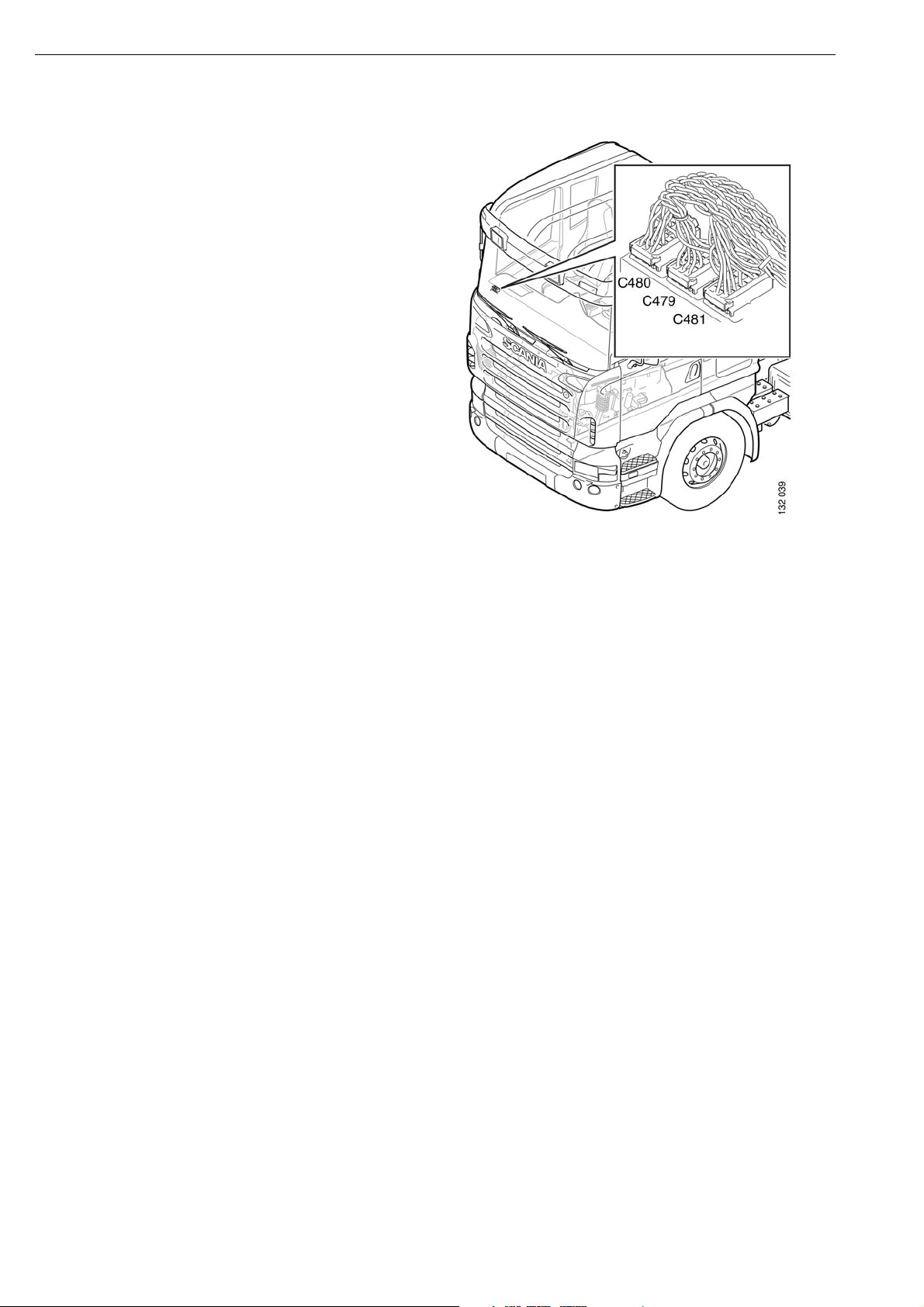
CAN network
To be able to troubleshoot in the CAN network,
it is important that you know about a number of
basic factors.
CAN technology has been developed to provide
a reliable transfer of data between different
components in the vehicle. It is based on serial
communication in two cables called CAN High
(CAN H) and CAN Low (CAN L).
The vehicle divides communication between
three CAN buses, red (C480), green (C479) and
yellow (481). This is to ensure good operation
and reliability.
10
©
Scania CV AB 2005, Sweden
16:07-01
Page 11
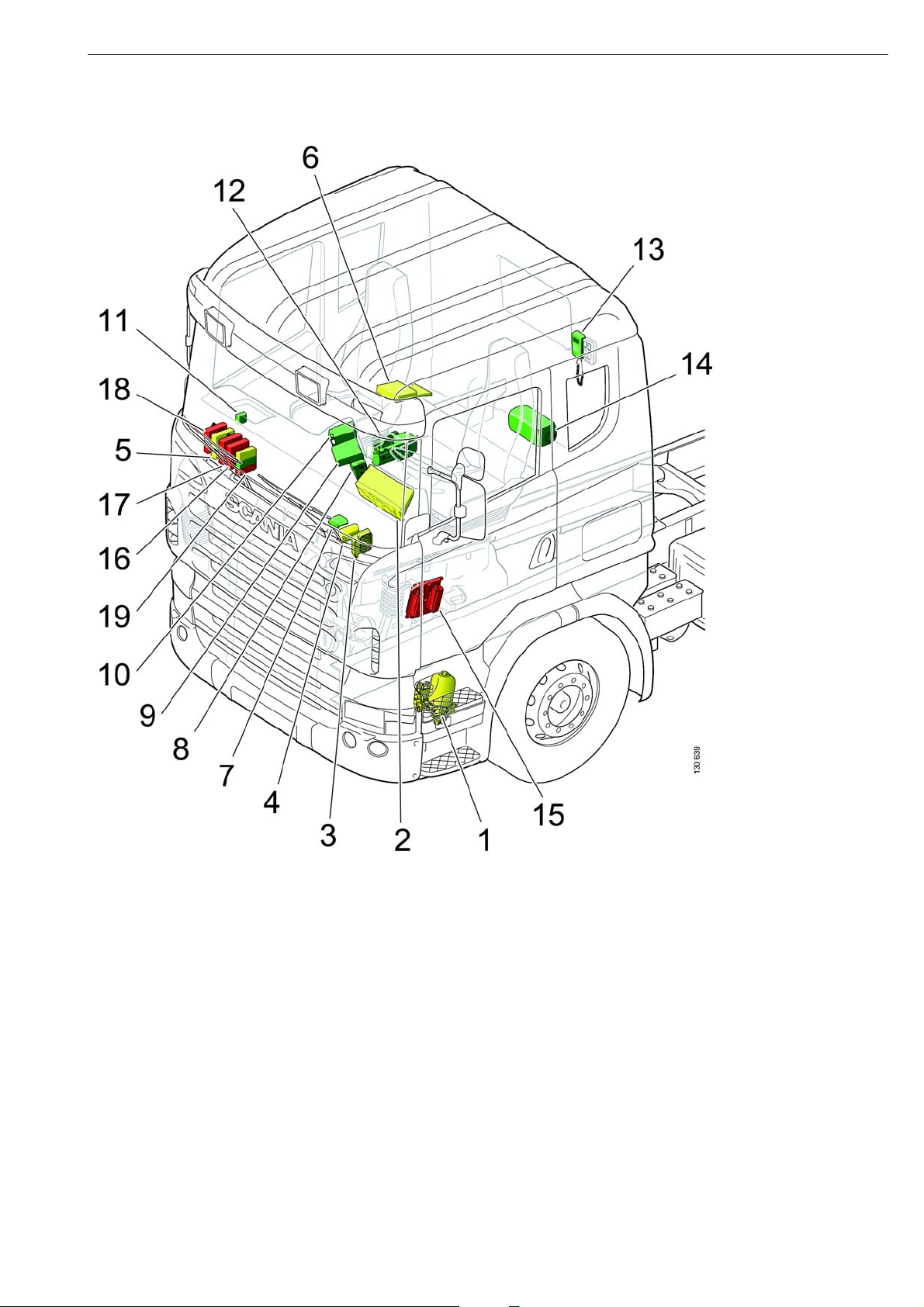
Location of control units in the cab
The illustration shows the basic location of the control units when the P series was introduced.
The control unit location may vary somewhat depending on the cab type and equipment level.
1 APS
2 ICL
3 VIS
4 LAS
5 BWS
6 TCO
7 CSS
8 ACC
9 AUS
11 RTG
12 WTA
13 CTS
14 ATA
15 EMS
16 BMS
17 SMS
18 GMS
19 COO
10 RTI
©
16:07-01
Scania CV AB 2005, Sweden
11
Page 12
Overload on the CAN buses
Faults can arise in ECU systems, resulting in the
systems continuously sending incorrect
messages to the extent that the communication
does not function. This is called overload.
Overload can result in some messages being
transmitted and others not. In turn, this means
that some functions will be missing. If the green
CAN bus is overloaded, this may also mean that
SDP3 cannot be used.
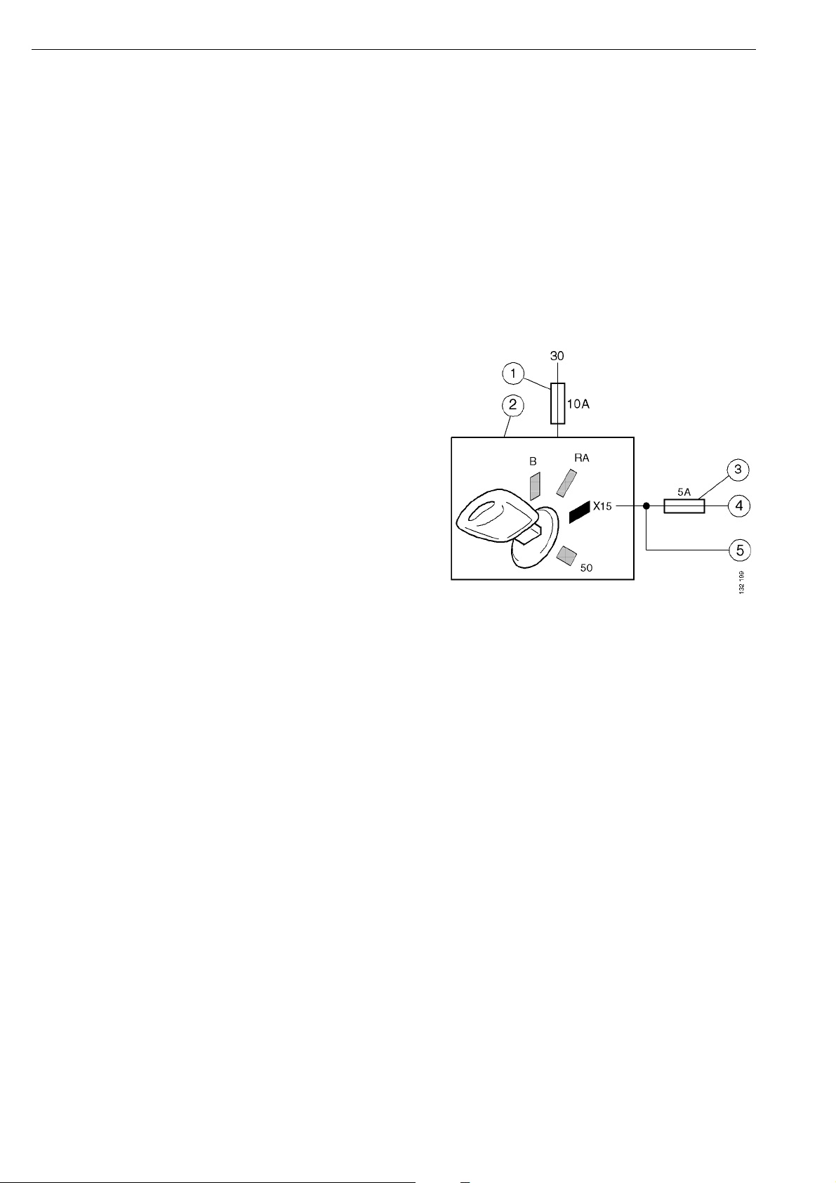
Activation of the control unit
For a control unit (ECU) to be able to receive
CAN messages, it must have a power supply
from the battery (30-supply), and an activation
signal. The control unit is in most cases
activated by the starter key being turned to the
drive position (15-supply).
The starter lock (2) receives voltage from the
30-supply via a 10 amp fuse (1).
An X15-supply runs from the starter lock to the
CAN buses' control units.
To reduce the risk that control units on the red
bus (5) lose the 15-supply due to a fault on the
green or yellow buses (4), the control units on
the latter buses are protected by an additional
fuse (3).
12
©
Scania CV AB 2005, Sweden
16:07-01
Page 13
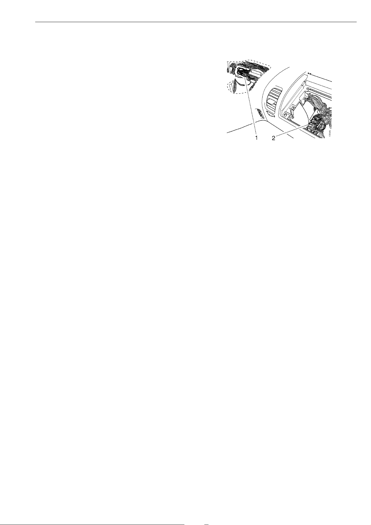
Connector C483, which supplies the control
units on the yellow and the green buses with
15-supply, is mounted centrally under the
instrument panel (1). Connector C482, which
supplies the red bus with 15-supply, is mounted
under the central electric unit (2).
There are, however, control units which are not
activated by the 15-supply, for example:
- LAS, which is active when the truck is
locked.
- AUS, which is activated as soon as the key is
in radio position.
- ATA/WTA is only activated after a command
from CTS/ACC.
Vehicle internal time
The vehicle internal time is independent from
the time the driver can see and change on the
instrument cluster (ICL).
The vehicle internal time is sent as a message
from the instrument cluster to other control
units. The vehicle internal time is used for
recording times of fault codes which are
generated by the control units. The vehicle
internal time can only be changed using SDP3.
Where a vehicle is equipped with a tachograph
(TCO), the ICL synchronises the vehicle
internal time with TCO internal time. In this
case, the vehicle internal time is set using the
special instrument which is used for setting the
TCO.
16:07-01
©
Scania CV AB 2005, Sweden
13
Page 14

ECU settings
Scania manufactures vehicles with different
specifications. The vehicle model depends on
customer needs and requirements. For the
electrical system in a truck to work correctly,
the control units in the CAN network must be
adjusted so that they correspond to the vehicle
configuration (specification). For example, it is
crucial that the brake and suspension systems
are adjusted for the correct number of wheel
axles.
This adjustment is done during manufacture of
the vehicle, by setting a number of parameters
in the control units. These parameters, and
some other information, are written to a file
(the SOPS file), which is stored in COO and
ICL.
For some conversions, the SOPS file must be
changed if the vehicle is to function correctly.
The affected control units are then set using the
updated SOPS file. It is possible to make minor
changes to the SOPS file, such as after
changing to a fuel tank with larger volume,
using SDP3. More advanced changes, however,
may require the SOPS file to be sent to Scania.
COO continuously checks that certain safety
critical control units have not been renewed. If
an ECU is renewed, the new one must be
loaded with the correct parameters from the
SOPS file. This can also be done using SDP3.
14
©
Scania CV AB 2005, Sweden
16:07-01
Page 15

Cable harness
With the introduction of the PRT series, Scania
has also introduced a new concept for earthing
electrical components. This concept will
provide more reliable and clearly arranged
earthing. Scania has also used a more limited
number of connector types for connections,
mainly for those connections located outside
the cab. The marking of the cables has also
been changed to make them more distinct.
Finally, the wiring diagrams have been changed
in a number of ways (see "Wiring Diagrams").
16:07-01
©
Scania CV AB 2005, Sweden
15
Page 16

Power supply
The power supply system contains mainly the
components and cables that handle high
currents.
On PRT series vehicles, the electrical path
between the alternator and the batteries is
shorter in comparison with the 4-series. The
main advantage of this is that the total voltage
drop from the alternator to the batteries is less,
which means that more power can be fed to the
batteries.
The power supply system supplies all other
systems with a voltage supply and earth. This is
done via connections 15, 30, 12V/30, 12V/RA,
58 and 61. Each system may have one or more
connections.
The X designation is a new feature on the P, R,
and T series which has been introduced for
different cable functions. If a cable transmits
information, rather than a power supply, it is
marked with the prefix X. The activation signal
for the CAN bus control units X15 and the
power supply in drive position 15 are examples
of this.
16
©
Scania CV AB 2005, Sweden
16:07-01
Page 17

Signal Function Type Direction Functional
source/destination
Physical
source/
destination
X15 Drive position Digital In Coordinator system Starter lock
X58 Relay Digital In Visibility system CUV
X61 Relay Digital In Visibility system CUV
XRA Radio Digital In Coordinator system Starter lock
XB Key inserted Digital In Coordinator system Starter lock
XRAARadio Digital Out Coordinator system Voltage
converter
XBA Key inserted Digital Out Coordinator system Central
electric unit
15 Drive position Voltage supply Out Other system Central
electric unit
30 Battery
voltage
12V/30Battery
voltage
12V/RABattery
voltage
Voltage supply Out Other system Central
electric unit
Voltage supply Out Other system Voltage
converter
Voltage supply Out Other system Voltage
converter
31 System
Earth - Other system
earthing
58 Parking lights Voltage supply Out Other system Central
electric unit
61 Charging
status
Voltage supply Out Other system Central
electric unit
Bodywork Voltage supply Out Bodywork interface
Tag axle lift Voltage supply Out Tag axle lift Junction
block
Visibility
Voltage supply Out Visibility system
system
Tachograph Voltage supply Out Tachograph system
Starter motor Voltage supply Out Starter motor
system
Junction
block
16:07-01
©
Scania CV AB 2005, Sweden
17
Page 18
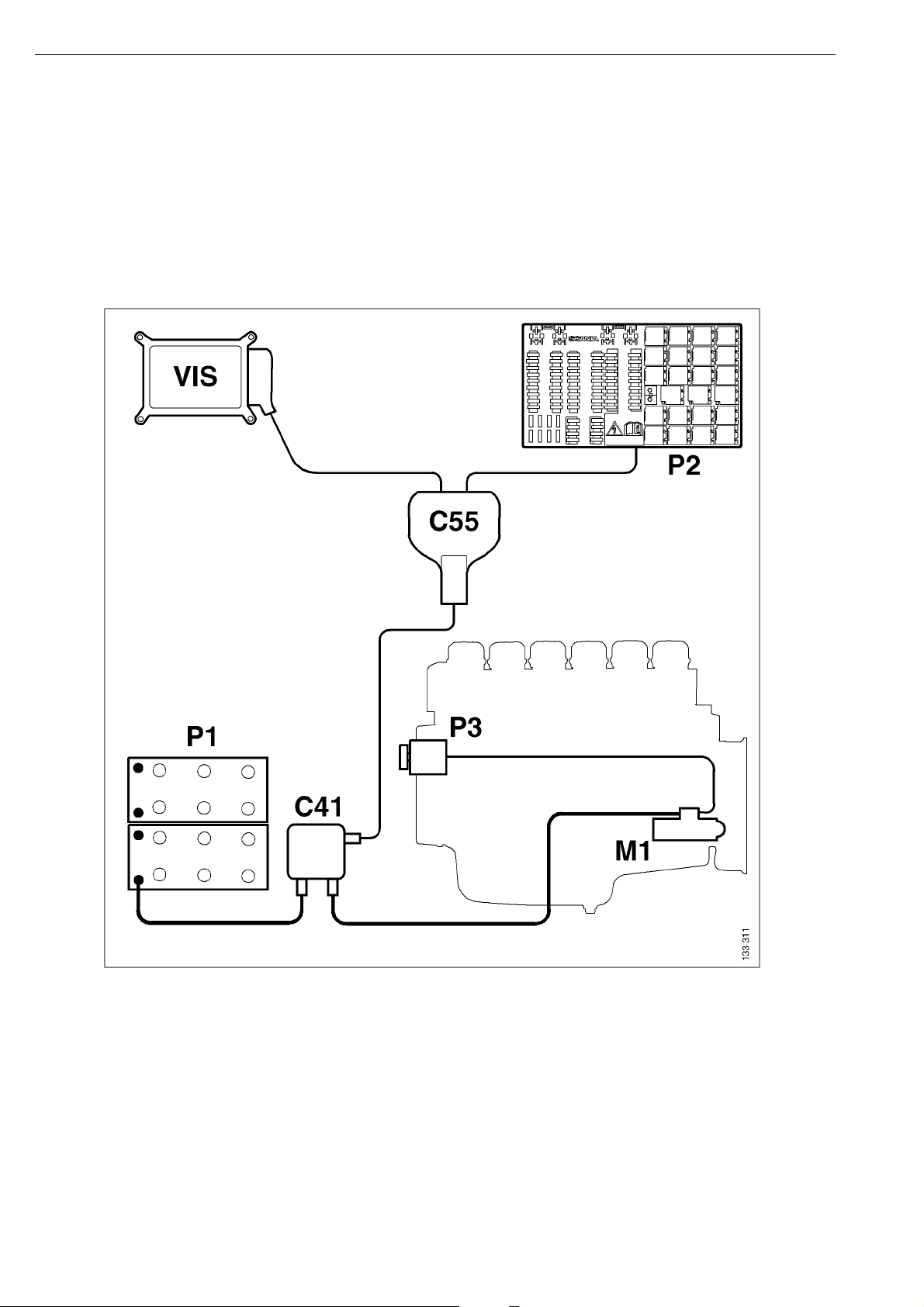
Positive supply
The power supply system has been simplified in the Scania vehicle range.
The cable from the alternator P3 goes via the starter motor M1 and a junction block C41 to the battery
P1. (A service switch is also fitted before the battery in most cases.) A cable goes from junction block
C41 to junction block C55 which provides a supply for the central electric unit P2 and visibility
system VIS.
18
Schematic diagram of the power supply
©
Scania CV AB 2005, Sweden
16:07-01
Page 19
Moulded cables
Moulded cables are cables comprising several
individual wires with an inner and a common
outer sheath of polymer. The proportion of
moulded cables on the chassis is greater on the
PRT series than on the 4-series. This reduces the
risk of open circuits and short circuits caused by
chafed sheaths. Scania has also produced a new
range of moulded cables with thinner sheaths.
This is to make the cable harness in the frame
member easier to handle.
Note that the colours of the moulded cables do
not always agree with the colours of the
corresponding individual leads inside the cab.
16:07-01
©
Scania CV AB 2005, Sweden
19
Page 20
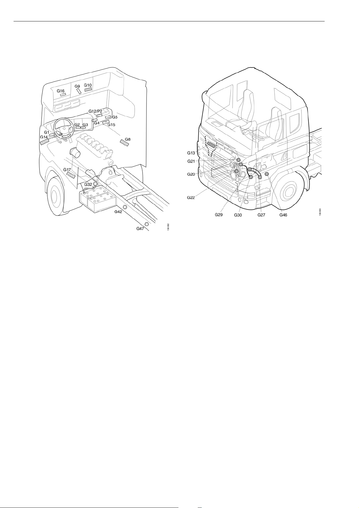
Earthing
20
The main earthing lines are the left-hand frame member, engine and gearbox block, and the cab
structure. To improve contact with the frame member, Scania has introduced a new earth bolt that is
pressed firmly into the frame member. Scania has also introduced special earthing points on the frame
for bodybuilders (G46 and G47).
Most of the components on and behind the instrument panel are earthed to one of the 21-pole earthing
blocks (G1-G5) that are distributed behind the instrument panel. From each of these blocks a common
cable runs to earthing points in the cab structure (G10, G14, G15). The earth cables are connected to
these earthing points with ring terminals. The most important components and the components
consuming most current are earthed directly to these earthing points. These earthing points can be
found e.g. in the roof and the lower part of the A-pillars.
©
Scania CV AB 2005, Sweden
16:07-01
Page 21
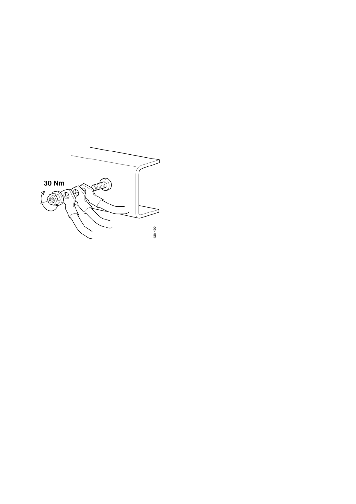
Fitting the frame earth bolt
A maximum of three ring terminals should be
connected to avoid an overload on the earthing
point. If you need to connect more ring
terminals, you must fit more earthing points.
Earth connection nut, part number: 815133
A maximum of three ring terminals may be
connected to each earth bolt. At least 1 turn of
the bolt thread should be visible on the
tightened joint. The earth connection nut is
tightened to 30 Nm using a hand tool.
Fitting the frame earth bolt
If the earth bolt has broken or provides a poor
contact with the vehicle, it must be renewed.
Contact is provided between the grooves in the
bolt and the frame member.
Note that the quality of the hole is crucial for a
good electrical connection. Therefore any rust
or paint in the hole must be removed before a
new earth bolt can be fitted.
The hole must be checked before a new earth
bolt is fitted, regardless of whether you are
using the old hole or drilling a new one. If the
hole is not within the tolerances, 14.2 mm
±0.1 mm, a new hole must be drilled.
If a new hole has to be made, it should be
drilled/reamed in stages up to the final
diameter.
It is important for the hole to be made at right
angles to the frame and for the hole to be as
cylindrical as possible.
16:07-01
©
Scania CV AB 2005, Sweden
21
Page 22
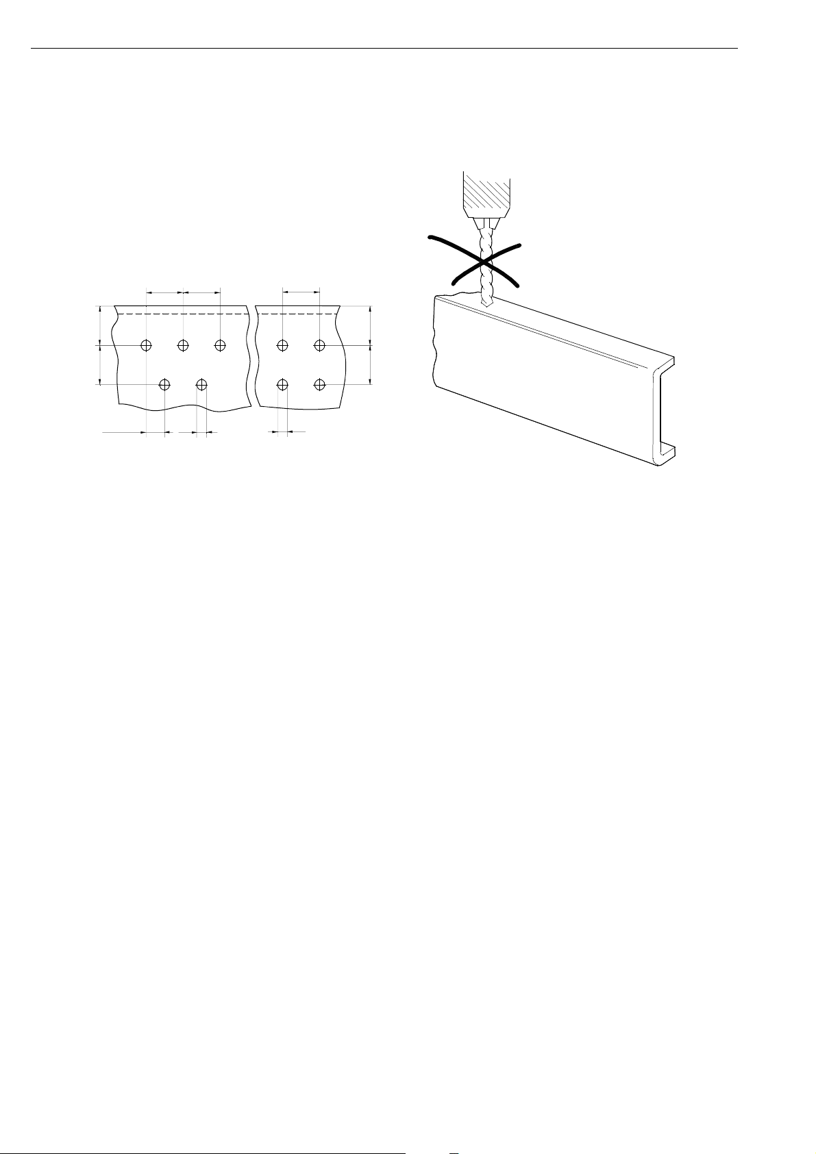
Drilling holes
The pre-drilled holes should be used whenever
possible.
If new holes have to be drilled closer to an
existing hole than the picture shows, the
existing holes should be welded closed, refer to
the Bodywork Manual.
IMPORTANT! It is not permitted to drill holes
in the frame flanges.
B B
A
C
B/2
D
B
D
A. Distance hole - frame flange should be at
least 3 x D and also at least 40 mm.
B. Minimum 4 x D.
C. Minimum 3 x D.
A
B
b129114
b129113
Holes are only to be drilled in the web of the
side members. The strength and service life of
the frame can be drastically affected by an
incorrectly positioned hole. The only
exceptions to this are holes drilled in the front
part of the frame and in the rear overhang in
areas where the loads are low.
22
©
Scania CV AB 2005, Sweden
16:07-01
Page 23

Hole diameter for earth bolt
NB! The hole must be within the tolerance
14.2 mm ±0.1 mm. If the hole is too large, the
contact surface will be too small and this will
result in too poor a connection.
The nut is tightened using a hand tool until the earth
bolt flange is in contact with the frame, but to a
maximum of 50 Nm. If the nut is tightened more than
this, there is a risk of the bolt breaking. If the earth
bolt can be tightened quite easily in the frame, this
indicates that the hole is too large. The grooves on
the earth bolt must be in good contact with the frame.
Frame earth bolt part No: 1743995
Flange nut part No: 815134
Check
The clearance between the earth bolt flange and the
frame should be a maximum of 0.2 mm. If the
clearance is greater than this, the hole is too small.
Tap out the bolt, ream the hole to the correct size and
fit a new earth bolt.
16:07-01
©
Scania CV AB 2005, Sweden
23
Page 24

Connectors
0
9
Four types of connectors are used for around 85% of all connections in the vehicles. These types
are:
MCP is used for all switches and most cable
joints in the cab. These have a number of
different codes. This reduces the risk of
2
2 1
1
incorrect connections when connecting cable
joints in the large cable harness in the cab.
DIN and Deutsch connectors. These are used
for most connections outside the cab.
MQS for connecting sensors in the cab
24
©
Scania CV AB 2005, Sweden
16:07-01
Page 25
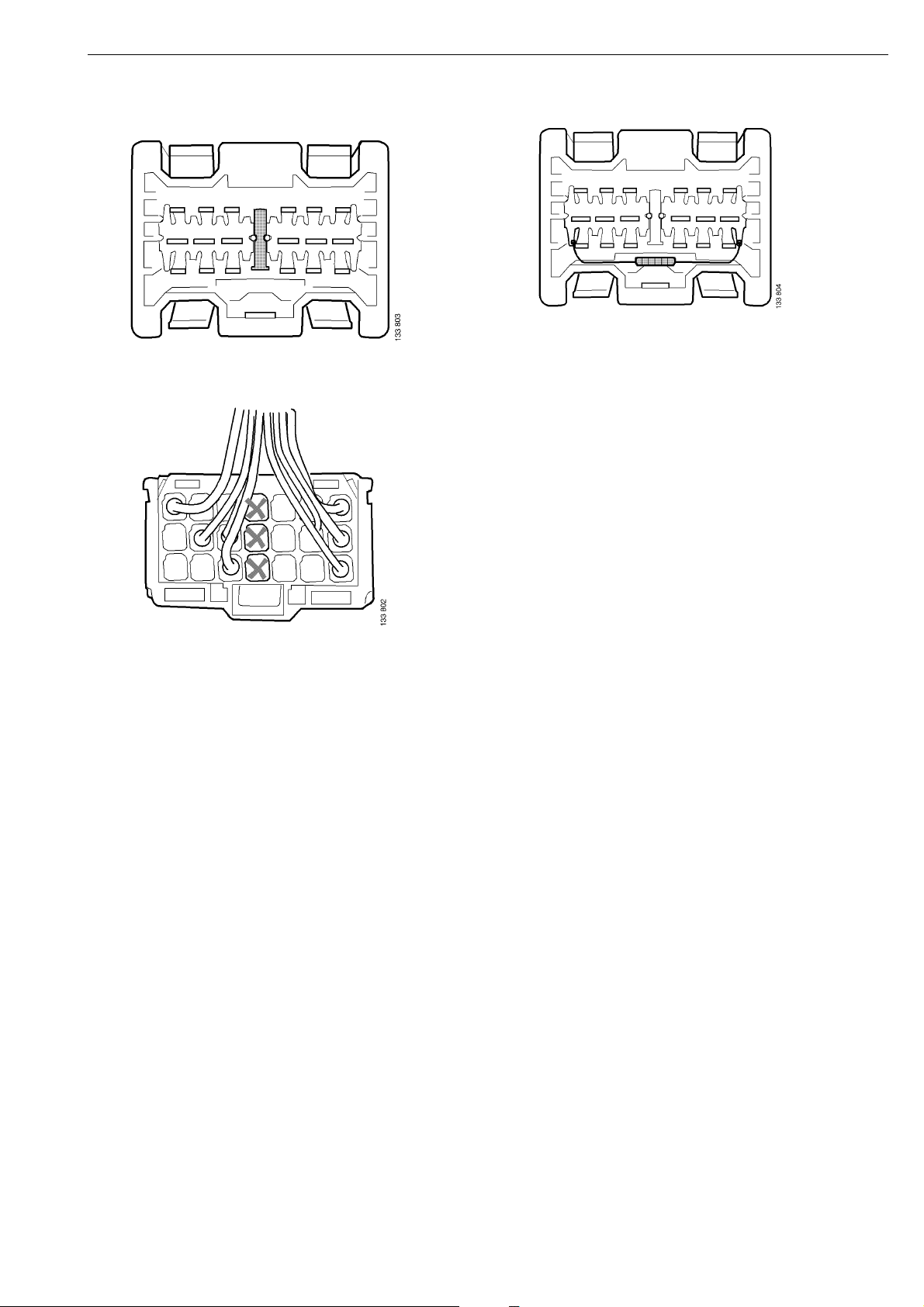
CAN bus connection block
Some of the CAN bus connection blocks are
fitted with termination resistors. Renew the
connection block if the termination resistor is
faulty.
The middle row on the CAN bus connection
block is inactive. Do not connect any
equipment there.
16:07-01
©
Scania CV AB 2005, Sweden
25
Page 26

User functions
User functions are defined as "An electrical
function on the vehicle which a user, for
example a driver or mechanic, can experience
or affect".
A simple example of a user function is coolant
temperature which is shown in the instrument
cluster.
User functions are partially a new feature, as
we have not talked in terms of these before.
Most user functions are, however, "spread"
across several ECU systems, which differs
from the 4 series.
The ability to communicate between different
control units means that one ECU can use the
information coming from a sensor that is
connected to another ECU.
This, however, means that the cause of a fault
can be more difficult to find. If, for example, a
sensor gives incorrect information, the
information can be transmitted through the
system and generate fault codes in several
systems which use or forward it. To find the
source of a fault, the path of information
through the system should therefore be
examined. The possible information paths in
the system are described in different scenarios
which are called function diagrams.
A function diagram illustrates graphically how
the different systems interact during the event/
task. The horizontal lines illustrate signals and
events. The vertical lines are a time axis which
represents the ECU or component stated at the
top of the line.
Function diagrams are found under the tab with
the same name in the User Function view in
SD3.
26
©
Scania CV AB 2005, Sweden
16:07-01
Page 27

Function diagrams
Coolant temperature display: The engine control unit reads the value on the coolant temperature
sensor. The information is then sent via the coordinator to the instrument cluster.
©
16:07-01
Scania CV AB 2005, Sweden
27
Page 28

Wiring Diagrams
In SDP3, separate circuits are shown for each component connection. These are complemented in the
service literature with more detailed wiring diagrams which instead are shown complete per system.
Subdivision
The table below shows how the wiring diagrams in the service literature are subdivided and which
systems they cover. In general there is one wiring diagram for each defined system in the vehicle,
including the ECU system and the DEC system.
In some cases, one wiring diagram covers several different systems. The systems included are then
grouped under a common designation, known as a system family. See example 'AHS' in the table. The
AHS (auxiliary heater) system family includes the ATA (air to air auxiliary heater), WTA (water to air
auxiliary heater), CTS (auxiliary heater control unit) and SSH (short-stop heater) systems.
In many cases, there is not enough space for all the information on one system on one single wiring
diagram. The diagram is then divided into several sheets. The sheet subdivision system can vary from
system to system, dependent on the solution which is best for that system. Sheets can for example
show different vehicle configurations or different control unit variants for the same system.
Wiring
Diagram
ACL Central lubrication
AHS ATA - Auxiliary heater (Air to Air) SSH, short-stop heater
ALT Scania Alert
APS Compressed air supply
AUS Audio system Radio (Basic)
AWD All-wheel drive
BMS ABS - Anti-lock system
BWS Bodywork interface
CAT Electric cab tilting Crewcab
CBR Comm. broadcasting radio
CCS ACC - automatic climate control MCC, manual climate control
CEH 230 V socket
COO Coordinator
CSS Crash safety
Included in the ECU system Included in the DEC system
WTA - Auxiliary heater (Water to Air)
CTS - auxiliary heater control unit
EBS - Electronic brake system
28
DIS Adaptive cruise control
EEC Emission control
EMS Engine management system
©
Scania CV AB 2005, Sweden
16:07-01
Page 29

Wiring
Included in the ECU system Included in the DEC system
Diagram
FAS Hand-held computer for vehicle analysis
FHS Fuel preheating
GMS OPC - Opticruise
RET - Retarder
HVF Road toll registration
ICL Instrument cluster
INL Interior lamp
KIT Kitchen module
LAS Lock and alarm system MCL Central locking without alarm
MIA Rear view mirror adjustment
MIH Rear view mirror heating
MOP Mobile phone
POW Power supply
RDL Differential lock operation
REF Refrigerator
ROH Roof hatch
RTG Interface for vehicle data
RTI SVIP - Vehicle data
SCS Seat control system
SMS Suspension system
SUA Sun visor adjustment
TAL Tag axle lift
TCO Tachograph
VIS Visibility system - External lighting,
windscreen wipers/washers and horn
Flashing beacon. Headlamp level
adjustment
WIW Window winders
16:07-01
©
Scania CV AB 2005, Sweden
29
Page 30

Type
2
4
3
1
BMS T
ABS1
1 833 768
1/1
1. Information window
In the lower right corner of the wiring diagram there is a window with information which identifies the
diagram. The system designation, the control unit designation (if required), sheet number and whether
the system applies to trucks or buses is stated in the window. At the bottom of the window there is (if
required) a chassis number limit.
Sometimes specific complementary information is required for a wiring diagram. Where required, this
is found translated into the relevant language above the picture of the wiring diagram in the display
tool.
30
©
Scania CV AB 2005, Sweden
16:07-01
Page 31

2. List of components
In the upper right corner of the wiring diagram the electric components shown on the diagram are
listed. Component codes and location in the diagram are specified.
3. Cable marking
PRT series wiring diagrams have all cables drawn.
Example of cable markings:
BMS212.GN-0.75 [P2:A-2]
• BMS: System designation. This is also marked on the physical cable in the vehicle, which means
that it is easy to identify the correct wiring diagram for a cable.
• 212: Serial number for the cable. This is also marked on the physical cable in the vehicle.
• GN: Colour marking, in this case green.
• 0.75: Cable area.
• [P2:A-2]: Address showing where the other end of the cable is connected. In this case: Pin A-2
on the central electric unit. As each cable is drawn in the diagram, address marking is only
provided if the cable is very long and difficult to overview.
Colour markings used:
BK Black
BN Brown
BU Blue
GN Green
GY Grey
OG Orange
PK Pink
RD Red
VT Violet
WH White
YE Yellow
16:07-01
©
Scania CV AB 2005, Sweden
31
Page 32

4. References
References to other diagrams can be given on the wiring diagram. If references apply to a diagram
which covers a different system the system name is given at the point where the cable ends (i. e. ICL).
If references apply to a different sheet within the same system, the sheet number is specified
alongside the component where it subdivides (i. e. See sheet 2).
In some special cases a longer reference description is considered to be required. Shorter sentences
can then be found on the wiring diagram, always only in English.
32
©
Scania CV AB 2005, Sweden
16:07-01
Page 33

16:07-01
©
Scania CV AB 2005, Sweden
33
Page 34

Central electric unit
The central electric unit (P2) distributes power
to other systems and functions in the vehicle.
Each connection is normally protected by a
fuse and receives power supply via relays in the
central electric unit.
The central electric unit is also numbered
underneath. For connection of accessories,
please refer to the Bodywork Manual.
34
A table showing the location and numbering of
the fuses and relays is provided inside the cover
of the central electric unit.
©
Scania CV AB 2005, Sweden
16:07-01
Page 35

Repairing cables
116952
Tools
Number Description Picture
588 200 Cable stripper
588 207 Crimping tool
588 220 Stripping tool
587 602 Hot air gun
00:1421
You should avoid splicing a cable wherever possible. Each joint is a weak point and possible source
of faults. Damage may however occur on the cable harness and components. In order to avoid
renewing the entire cable harness, it may be necessary to splice a single cable.
1 Use Scania Diagnos to find the defective cable or circuit.
2 Adjust the cable length so that the joints can be positioned where the cables are straight and
protected.
3 Splice on a new cable or component. Use a multimeter and Scania Diagnos to make sure that
there are no open circuits or short circuits in the cable harness.
©
16:07-01
Scania CV AB 2005, Sweden
35
Page 36

Work Description
1 Remove any defective component from the vehicle.
2 Release the cable and clean dirt and grease from it.
3 Mark on the cable where the centre point of the joint should be. It is preferable to place the joint
between two cable retainers.
Note: Remember to add measurement A to the marked centre point so that the cable from the control
unit will not be too short.
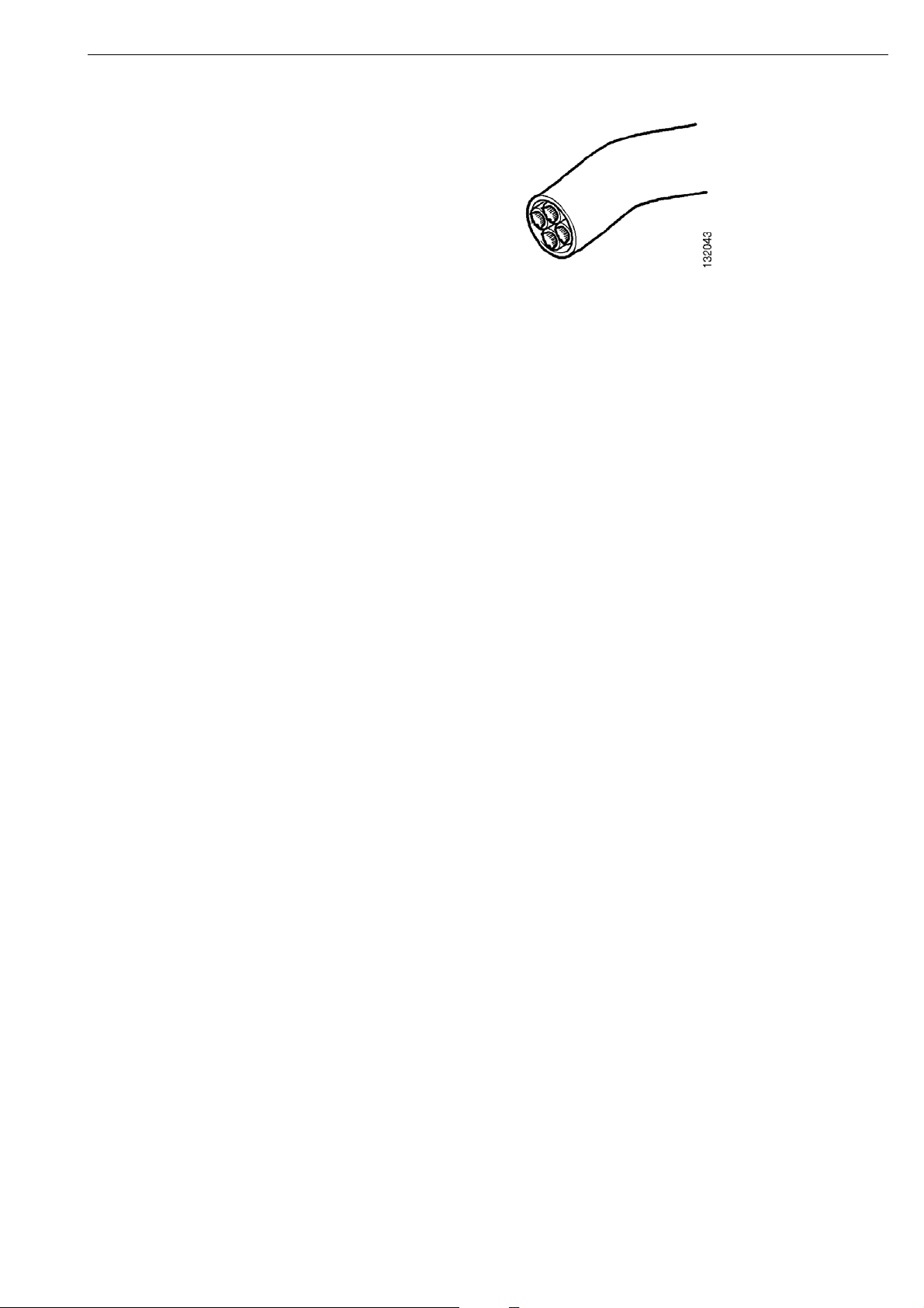
4 Cut the new cable as illustrated below. Add measurement B to the marked centre point.
2 wire cable
4-wire cable.
The charge air pressure and temperature sensor and oil pressure sensor have 4 wire cables
36
©
Scania CV AB 2005, Sweden
16:07-01
Page 37

5 Strip the cables using stripping tool 588 220. See illustration. Make sure that you do not damage
the cable insulation.
16:07-01
©
Scania CV AB 2005, Sweden
37
Page 38

6 Cut the cable as illustrated below. The centre line in the illustration is the mark on the cable.
7 Locate the joints on the wires as illustrated below.
8 Strip off 7 mm of the insulation from the ends of the cables with cable stripper 588 200.
2 wire cable
4 wire cable
38
©
Scania CV AB 2005, Sweden
16:07-01
Page 39

IMPORTANT! The joint must be sealed so that no moisture can penetrate.
9 Fit 40 mm long shrinking tubing on each wire.
10 Fit shrinking tubing which is approximately 30 mm longer than the joint on the cable. Two
shrinking tubings are used for 4-wire cable.
11 Clamp on the sleeves using crimping tool 588 207.
12 Heat the sleeves with a hot air gun e. g. 587 602 so that adhesive is forced out from the ends of
the cables.
After the sleeves have been clamped on, the sleeves should be heated until adhesive is forced out.
13 Fit the wire shrinking tubing over the sleeves and heat it so that adhesive is forced out.
14 Fit the wire shrinking tubing over the entire joint and heat it so that adhesive is forced out.
15 Refit the cable. One of the rubber teeth in the cable retainer may have to be cut off if a new
component has been fitted.
16:07-01
©
Scania CV AB 2005, Sweden
39
Page 40

Troubleshooting
Troubleshooting using SDP
A PC-based diagnosis and programming tool is
available for troubleshooting the ECU systems
(SDP3). To be able to use SDP3 on a vehicle, an
interface (VCI) and a hardware key (USB
dongle) are required.
Unlike the 4-series, the VCI is now connected
directly to a CAN bus (the green CAN bus). The
VCI that is needed is called "VCI 2" and will
only work on the PRT series vehicles. Refer also
to the user instructions for SD3.
40
©
Scania CV AB 2005, Sweden
16:07-01
Page 41

Vehicle-based troubleshooting
IVD (In-vehicle Diagnostics) is the designation
of Scania's vehicle-based troubleshooting. To
make it easier for the driver to describe a fault
on the vehicle when he/she speaks with a
workshop or to Scania Assistance, fault codes
can be read in the vehicle display on the
instrument cluster (ICL).
It is only possible to read fault codes when the
vehicle is stationary.
1 The designation on the control system
which generates the fault code for the case
shown in the picture is the EMS.
2 The fault code number is 37 in the example
shown.
3 The part number of the control unit which
generated the fault code is 1120511 in the
example shown.
4 The number of times a fault with the
specified fault code number has occurred is
19 times in the example shown.
5 The snowflake in the bottom right-hand
corner indicates that the fault code was
active when it was retrieved from the
control unit.
16:07-01
©
Scania CV AB 2005, Sweden
41
Page 42

Troubleshooting the CAN cables
CAN communication is well tried and designed
to withstand interference. To reduce the risk of
interference, the CAN cables are twisted. This is
because the system reads voltage differences
between the cables to determine whether it is a
1 or a 0 and if the same interference is affecting
both cables, there will be no difference. The
greater the distance between them, the greater
the risk that one cable will experience more
interference than the other.
Example of a CAN network
42
©
Scania CV AB 2005, Sweden
16:07-01
Page 43

Note: In order to measure resistance in the
CAN cables, the power in the electrical
system must be switched off. No systems
must be disconnected.
As the voltage between CAN H and CAN L
varies continuously depending on whether a
"one" or a "zero" is being sent, the CAN
communication cannot be checked by
measuring with a multimeter. It is, however,
possible to check whether the termination
resistors are intact.
There must be two termination resistors on
each bus for the CAN communication to
function. The termination resistor can either be
"split termination" or a single resistor.
Split termination is a type of termination
resistor which is also a filter that removes high
frequency interference. Split termination
consists of two resistors which are fitted one
after the other on the cable. There is a capacitor
between the resistors which is connected to
earth. The capacitor allows all alternating
currents above a specific frequency to pass
through, which means that these are eliminated.
Connection block with termination resistors
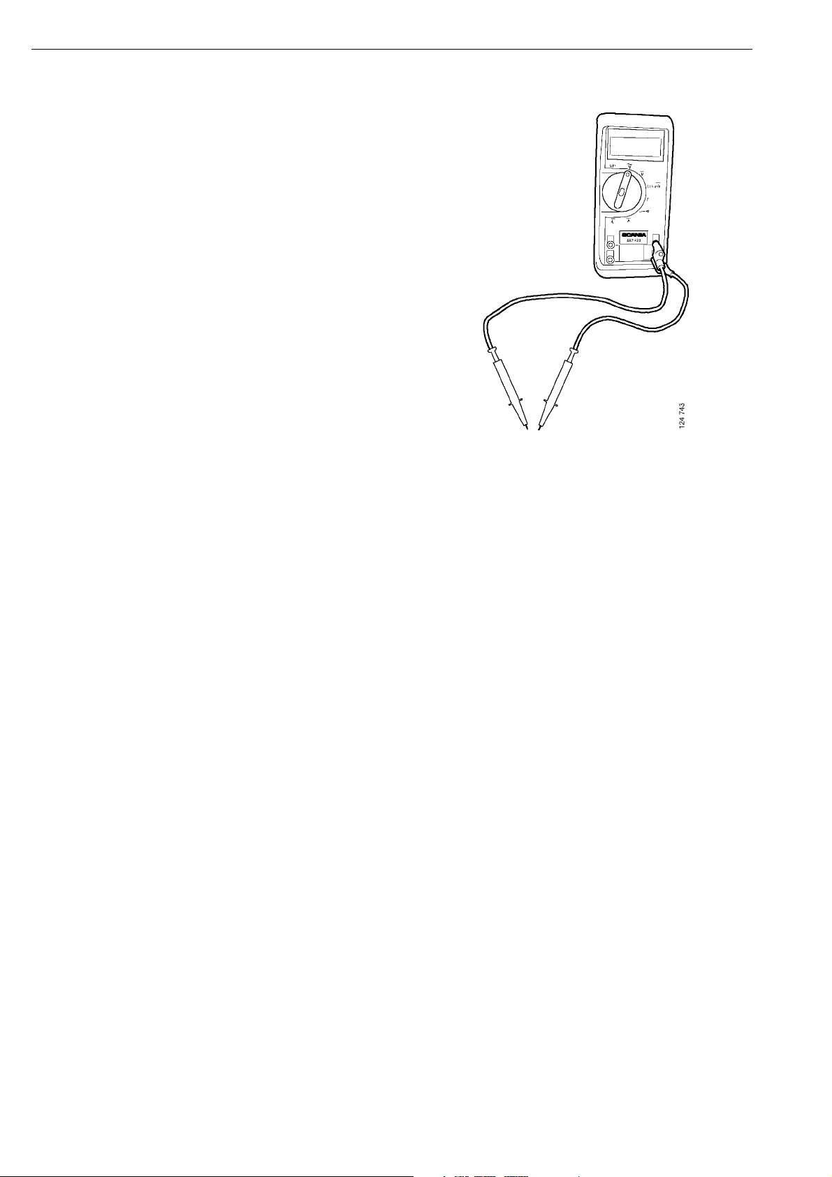
The integrity of the termination resistors can be
checked by measuring the resistance between
CAN H and CAN L using a multimeter. The
measurement should be made on the connector
for each CAN bus. One measurement probe is
held against one of the white cables' contact
pins, and the other measurement probe is held
against a contact pin of the other colour. The
resistance on each CAN bus should be
60 ohms. If it is 120 ohms this means that a
termination resistor is missing. If it is 40 ohms
or 30 ohms, this means there are one or two
termination resistors too many on that CAN
bus.
16:07-01
©
Scania CV AB 2005, Sweden
43
Page 44
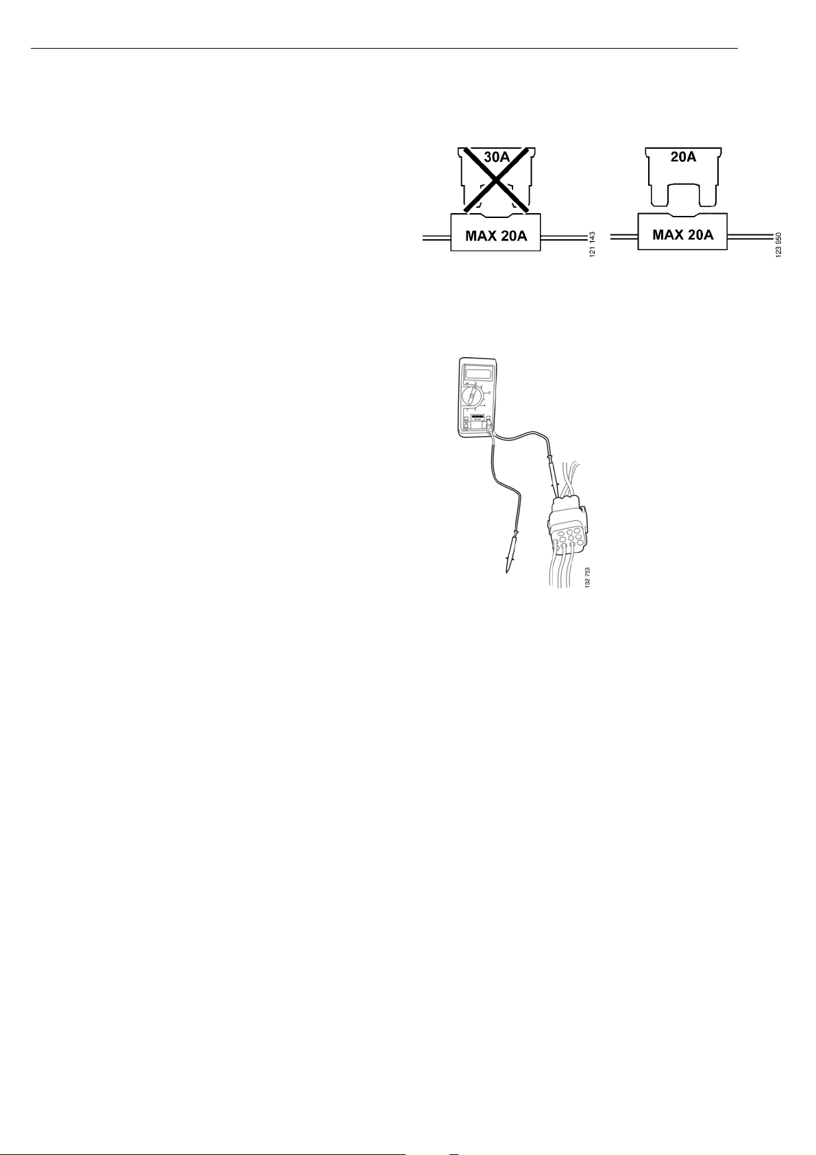
Things to be considered ...
Note: Always measure on the rear of the
connector.
• Never fit a fuse with a higher amperage than
permitted. The fuse is dimensioned for the
electrical system and its components.
• Avoid changing a fuse when the power
supply is still connected to it. This is to
avoid burns in the fuse holder.
• Always try to carry out voltage tests on a
connector from the rear of the connector.
This avoids damaging the pins and you do
not need to disconnect the connector
unnecessarily. A connector which has been
frequently disconnected can, in time, give
rise to a loose contact.
IMPORTANT! If a connector to a currently
active electronic control system is disconnected,
fault codes are often generated. Therefore
remember to check that no new and misleading
fault codes have been generated after
troubleshooting and repair.
44
©
Scania CV AB 2005, Sweden
16:07-01
Page 45

• When you are searching for an open circuit
between connectors, the following applies:
Never make a hole in a cable which is
located outside the cab to check whether it
is live. Moisture and salt can penetrate even
a very small hole and in time the cable will
form verdigris within the insulation. Such
an open circuit is almost impossible to see.
It is better then to cut the cable and make a
waterproof joint afterwards.
WARNING!
!
Never cut a wire with several internal leads
when it is live. There is a risk of a short
circuit which can result in personal injuries
and costly consequential damage.
16:07-01
©
Scania CV AB 2005, Sweden
45
Page 46

• Do not use a test lamp with an LED to
check whether there is a voltage to
components such as lamps, magnets,
motors, etc which are operated with
24 volts. A bad earth connection to the
circuit concerned is enough to switch on an
LED which then gives an incorrect result.
A test lamp fails to come on or comes on at
a very much reduced output in such a test.
The electrical system and components
should be checked using a multimeter.
46
©
Scania CV AB 2005, Sweden
16:07-01
Page 47

• Troubleshooting in electronic control
systems requires access to a multimeter
and/or PC with the Scania Diagnos
program.
• Electronic control systems generally store
a fault code in their control unit. The fault
code can be read off using Scania Diagnos.
It is generally possible to locate faults and
test various components relatively easily
using Scania Diagnos.
• Control Area Network, CAN
Certain electronic control systems operate
in networks with other control units and
components, CAN communication.
In electronic control systems which use
CAN communication, Scania diagnostic
tools should primarily be used for
troubleshooting.
16:07-01
©
Scania CV AB 2005, Sweden
47
Page 48

Short circuit
There are different types of short circuits:
• Short circuit to earth on live cables.
This often results in a fuse blowing or a
function being absent and a fault code is
generated in an electronic control system.
• Short circuit to earth on an earth circuit.
E.g the cable to the brake lamp switch is
earthed because a screw is screwed through
the cable. Normally that cable is earthed
via the brake lamp switch. The short circuit
does not cause any fuse to blow in this
case, but fault codes can be generated in an
electronic control system. Also different
electronic control systems can lose
functions since several functions are
required at the same time. These faults are
more difficult to find and it is necessary to
understand how the electronic system
operates.
48
©
Scania CV AB 2005, Sweden
16:07-01
Page 49

• Short circuit from one live circuit to
another circuit which is not currently live.
These types of short circuits can occur
because, for example, a screw is screwed
into a cable with several leads, or there is a
contact condition between two pins in a
trailer connection, so that normal lighting
turns on the direction indicator, activates
the tilt function on a connected tipper, etc.
These short circuits do not necessarily
cause any fuse to blow, but fault codes can
be generated in an electronic control
system.
Checking for a short circuit
Live cables
• Switch off the power or remove the
relevant fuse from the vehicle.
• Measure the resistance between the fuse
output and earth. If you touch the cable
harness at the same time as you study the
reading, a circuit in working order should
show a stable and infinite reading on the
multimeter. If the reading on the
multimeter is zero or if low resistance is
measured, this indicates a short circuit.
• To locate where in the cable the fault lies,
move the measuring probe to the next
section of the cable at the same time as you
disconnect the previous section.
Earth circuit
• Proceed in the same way as when checking
live cables, but you now know that the fault
is after the load (lamp) but before the
control ('make' contact).
16:07-01
©
Scania CV AB 2005, Sweden
49
Page 50

Open circuit
When there are open circuits in cables, the
fuses generally do not blow. What is known as
a current spike may be generated by this if the
cable or lead is loaded just when it is pulled,
torn or cut off. Then a fuse may blow but when
a new fuse is fitted it will hold, since there is no
longer any load there.
Fault codes are however often generated in
electronic control systems when there is an
open circuit on their cables. This is because
electronic control systems often keep watch
and communicate with their components.
Checking for an open circuit
Measuring the resistance
• Switch off the power in the vehicle
• Measure the resistance, e.g. from the fuse
holder and out towards the load. If the
multimeter shows zero or a low value, the
cable is intact.
Measuring voltage
• On a cable with battery voltage you can
locate the break by starting measuring from
the beginning of the cable, and then
gradually moving "backwards". The cable
always has battery voltage up to the break.
50
©
Scania CV AB 2005, Sweden
16:07-01
Page 51

Voltage drop
When resistance testing the cable in a currently
load-free circuit, you can obtain a misleading
measurement result which indicates that the
cable and its connections are OK.
Example:
A work lamp is not working. You remove the
bulb and measure directly in the bulb holder
(does not apply to a gas discharge light source).
There you obtain a value of 24 volts and think
that it was the bulb that was defective. But it
still does not work with a new bulb.
You measure the cable resistance and obtain a
value which indicates that the cables and their
connections are OK.
This is a misleading measurement result. With
such a measurement, the load on a cable is so
low that it is sufficient if just one copper wire in
the cable is intact or the connection is quite
poor to obtain a correct measurement result.
Under load, however, the conductivity becomes
much too poor and the bad cable or connection
then functions as a large resistance and a
voltage drop occurs. The greater the load the
greater the heat released at the voltage drop
point.
In the above case you should measure the
voltage across the lamp, directly on the input to
the bulb holder. If the multimeter shows
24 volts, the contact resistance is located in the
bulb holder. If the measurement shows a low
voltage, this is due to poor earthing or a voltage
drop before the lamp.
Generally, a voltage drop is checked with the
positive cable of the multimeter on the supply
side of the measured component, and the
negative cable closer to the load, across the
load, etc. When the circuit is activated, the
voltage difference is visible. If the circuit is
OK, the voltage drop should be a maximum of
1 Volt.
16:07-01
©
Scania CV AB 2005, Sweden
51
Page 52

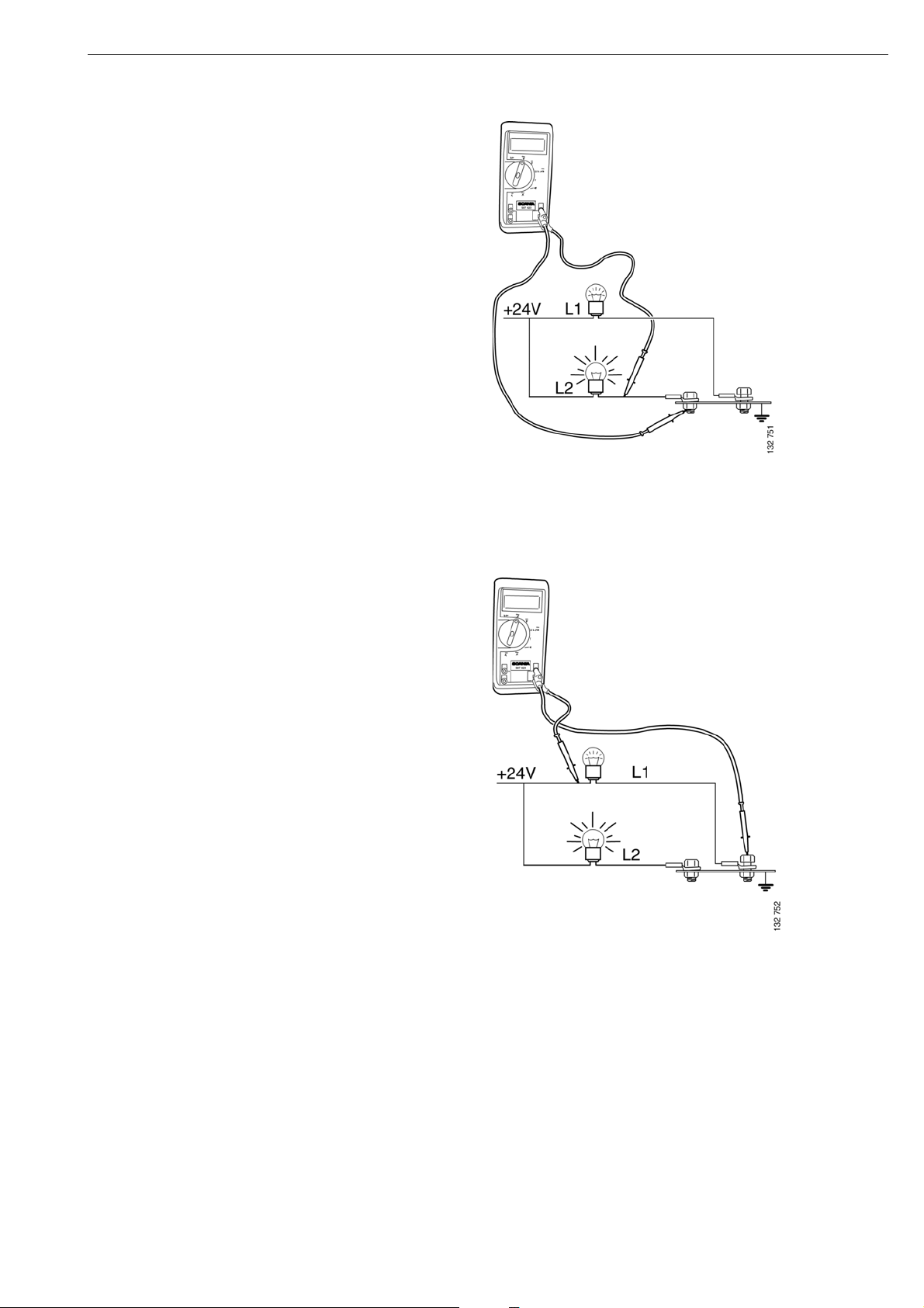
Earth fault
Earth faults in the light circuits or circuits with
warning lamps are frequently recognised
because the lamps do not come on at full
output.
Check using the same method as for a voltage
drop.
Good earth connection to the multimeter.
Correct voltage to L1, but the lamp is glowing
faintly.
52
©
Scania CV AB 2005, Sweden
Good earth connection to the multimeter.
Faulty earth connection to L1. The multimeter
shows a low value and the lamp L1 is glowing
faintly.
16:07-01
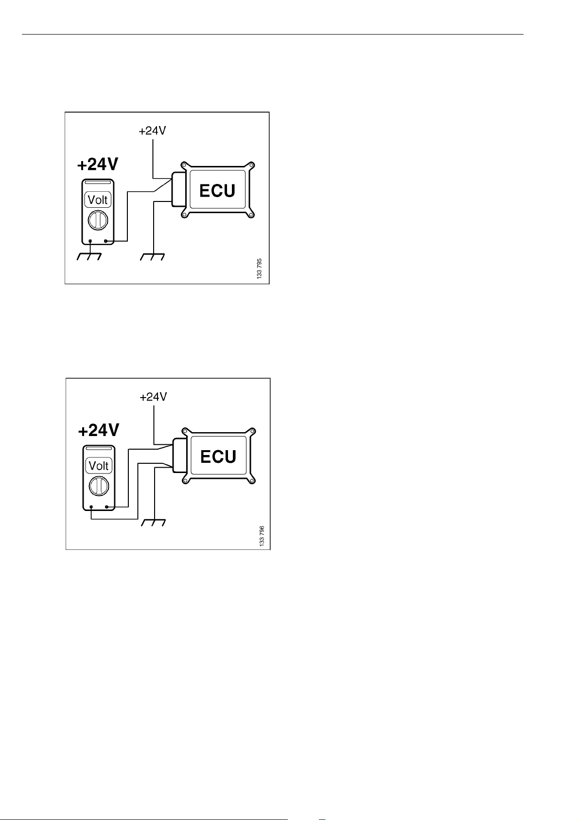
Page 53
A good earth connection is always dead.
Always make sure that there is a good earth
connection to the test equipment.
Good earth connection to the multimeter and
L2. No multimeter reading.
16:07-01
Faulty earth connection to L1 and multimeter.
L1 glows faintly and the multimeter shows a
low value. This gives a misleading voltage
value for L1.
©
Scania CV AB 2005, Sweden
53
Page 54

Earth faults often result in circuits which have no
common connection apart from the earth
connection quite suddenly having an effect on each
other.
If a common earth point for several different
components comes loose, e.g. from the chassis, the
current will be conducted to the nearest earth
point.
Earth faults in electronic control systems do not
always generate fault codes.
Examples 1 and 2:
Example 1
An earth bolt comes loose but is still held in the
ring cable terminal connectors of other circuits.
Now the current cannot be conducted to earth as
intended but the current is conducted to another
earth point. Then the current is conducted back
into another circuit and in this way circuits are
affected by each other, which they normally are
not.
1. Current via switch, through lamp, to earth
point, faulty earth point, on to motor, back
through the motor, to output on switch, on to lamp
and earths through the lamp and its earth point.
This means that the lamps are glowing and the
motor runs slowly and in the wrong direction.
Example 2
2. Current via switch, through lamp, to earth
point, faulty earth point, on to relay, back through
the relay, to output on switch, on to lamp and
earths through the lamp and its earth point. This
means that the relay operates and the motor is
running at full output, but the lamps are glowing.
54
©
Scania CV AB 2005, Sweden
16:07-01
Page 55

Communication problems on the CAN buses
Most functions in the vehicle are controlled via a network of control units. There are many
advantages with the new electrical system, e.g. performance, safety and a reduced number of cables.
Compared with conventional DEC systems, the use of CAN communication involves to some extent
thinking in new ways when troubleshooting.
It is normally very easy to troubleshoot in the network and rectify the fault using the Scania
diagnostic tool.
In some cases faults may occur which can be difficult to diagnose and rectify using SDP3. You must
then remember that the faults occurring in one function may originate in a component which
according to old ingrained ways of thinking should not have anything to do with the function. The
previous self-evident relationships between fault symptoms and the cause are no longer so selfevident. The symptoms which arise as a result of a specific fault may also vary depending on how
different vehicles are specified.
Examples are provided below of faults which can cause you, the mechanic, a lot of problems and of
ways in which you can carry out troubleshooting on the CAN cables. This is not a comprehensive
guide on how to tackle the obstacles which arise when there are problems with communication. They
do, however, provide examples of how to approach the search for the causes of faults in the electrical
system.
Before you start troubleshooting, you should have determined whether the fault occurred in
connection with some other activity, e.g. connecting bodywork, installing accessories, etc. or whether
it just occurred for no apparent reason.
16:07-01
©
Scania CV AB 2005, Sweden
55
Page 56

For troubleshooting you need
• SDP3 + VCI
• Measurement adapter kit 99511
• Multimeter
• Chart of the location of the control units on
the CAN buses (see page 64).
• Fault code descriptions.
If SDP3 has not identified any control units,
you will not obtain any fault code description
in the program. This can be resolved by going
to the SDP3 menu under "view" and "search
for fault codes". There you can obtain a list
with fault code descriptions for each
supplementary number. You can find the
supplementary number via the diagnostics
position (IVD) on the instrument cluster (ICL),
provided that the instrument can establish
contact with the control units and that there are
fault codes present. However, the instrument
cluster always shows which systems it expects
to receive a response from, i.e. which systems
are fitted on the vehicle. If there are no fault
codes, the instrument will respond with "no
errors" and if the instrument cannot establish
contact it will respond with "no contact".
56
In this case, however, it is not the fault codes
that are most important, since it is the
communication we want to test. If the
instrument cluster responds with "no errors",
this means that communication is working.
Systems such as CTS, ATA, WTA and AUS
must be running in order to establish contact
with them
©
Scania CV AB 2005, Sweden
16:07-01
Page 57

No communication on the green CAN bus
Open circuit or short circuit
Result: The diagnostic program is blank.
SDP3 cannot identify a SOPS file (see ECU
settings) when communication with COO is not
running. This means that you cannot see directly
which control units are fitted on the vehicle
either. In order to trace which systems are fitted,
you need to use the vehicle-based troubleshooting
(IVD) in the instrument cluster (ICL).
ICL gives fault code 104 for a communication
fault with the crash safety system (CSS). This is
because CSS is the only control unit on the green
bus for which there are fault codes in ICL. If the
vehicle is not fitted with CSS, ICL will not then
display any fault codes.
In the diagnostics position (IVD) on the
instrument cluster, you can scroll through a list of
the systems which have control units in the CAN
network on the vehicle. If you try to read the fault
codes, the instrument responds with "no contact"
for all control units which are on the green bus,
even if you in this situation do not know which
are included on that bus. With the aid of the chart
on page 64 you can see that it is only the control
units located on the green bus which are not
responding. In the instrument cluster it is also
possible to see which fault codes are generated by
the other systems. However, at present ICL
cannot read fault codes from TCO.
16:07-01
©
Scania CV AB 2005, Sweden
57
Page 58

From the information you now have, you can
reach the conclusion that there is no open
circuit on the green bus, e.g. in the diagnostic
socket, nor is there a fault on the cable between
VCI and the diagnostic socket, but that there is
a fault on the bus itself. An open circuit
towards the diagnostic socket would mean that
the instrument cluster (ICL) should be able to
communicate with the green bus whereas SDP3
would not be able to communicate with the
vehicle at all. You can also obtain information
about the status of the communication on the
VCI lamps (see user instructions for SD3). On
low-specification vehicles without any systems
on the green bus, ICL will not have any control
unit to communicate with so the chart showing
the location of the control units on the buses
becomes even more important. You will not
always know for certain whether there are any
systems on the green bus. The instrument
cluster always shows which systems the vehicle
is equipped with, and also therefore which are
expected to respond. At the moment, however,
the instrument cluster cannot communicate
with TCO.
• Check that the resistance between the CAN
cables and chassis earth is high enough. It
should be several thousand ohms or more.
• If there is a fault, disconnect the CAN
block for the green bus and measure via it
to find out which section of the bus the
fault is on.
• Disconnect the control unit concerned so
that you can distinguish between faults in
the control unit and cable faults. If there is
a cable fault - carry out troubleshooting on
the cables.
Troubleshooting and remedial action
SDP3 cannot establish contact with the vehicle
• Check VCI - indicator lamps will indicate
its status. Try to start the program again.
• Can ICL communicate with systems on the
green bus - if it can, the fault is in VCI or a
fault in the connection to the vehicle or in
the CAN block (C479) for the green bus.
The CAN blocks are concealed on the right
of the central electric unit area.
• On low-specification vehicles, it is not
certain whether there will be any systems
on the green bus. Check with ICL which
systems are available and compare with the
CAN bus chart (page 64).
• Check the voltage level in relation to
chassis earth on the green CAN bus. The
value should be approximately 2.5 V.
58
• Check that the termination resistance on
the CAN cable between CAN H and CAN
L is 60 ohms. All systems must be
connected and the vehicle should not be
supplied with voltage when measuring.
©
Scania CV AB 2005, Sweden
16:07-01
Page 59

Measuring voltage on the CAN bus.
It is not possible to measure the voltage in the
CAN bus and see whether it varies in the circuit!
The multimeter only measures the average value
for the CAN bus voltage level and this can
provide enough information to assess the
electrical status of the CAN bus. When it is
active, CAN H rises to approximately 4 V and
CAN L falls to approximately 1 V. This happens
so quickly that you cannot see this on a normal
multimeter. The average value shown on the
multimeter should therefore be approximately
2.5 V relative to chassis earth.
16:07-01
©
Scania CV AB 2005, Sweden
59
Page 60

Coordinator not supplied with power or malfunctioning
For troubleshooting you need
• SDP3
• Multimeter
• Chart of the location of the control units on
the CAN buses.
• Fault code descriptions.
• Measurement adapter kit 99511. To avoid
damaging the pins on COO and BWS, you
should use the measuring adapter with its
cable. No measurement should be carried
out directly on the pins because they are
very fragile.
60
©
Scania CV AB 2005, Sweden
16:07-01
Page 61

Symptom
If a coordinator is malfunctioning or not
supplied with power, this will result in a
stoppage.
SDP3 only shows the control units which
respond on the green bus. When SDP3 cannot
establish contact with the coordinator or with
ICL, you cannot obtain a SOPS file or see which
control units should have responded, or obtain
any circuits on those that have responded.
CTS, ATA, WTA and AUS must be activated so
that the diagnostic tool can establish contact
with them.
Fault codes in the systems on the green bus can
be read.
You can check which systems it has established
contact with in the diagnostics position (IVD)
on the instrument cluster (ICL). You can also
read fault codes from these systems. In this case,
however, it is not the fault codes that are most
important, since it is the communication we
want to test.
16:07-01
©
Scania CV AB 2005, Sweden
61
Page 62

Troubleshooting and remedial action
SDP3 only establishes contact with systems on
the green bus and ICL only with systems on the
yellow bus.
• Is fuse 19 intact and is there voltage to it?
• Check using measuring adapter 99508
whether the coordinator (COO) is receiving
voltage to pin connection 3 (30-supply), 81
(15-supply) and the earth on pin 5.
• If there is voltage to the control unit,
connect it and test again (there may be a bad
contact in the connector).
• If the fault disappears, inspect the relevant
pin in the connector and renew it if
necessary.
• If the fault remains, test with another control
unit.
62
©
Scania CV AB 2005, Sweden
16:07-01
Page 63

Earthing problems on control units
Systems which appear to be strange, without
showing any obvious faults during simple tests,
which result in inexplicable problems when
driving or using the system in some other way,
can often be assumed to have earthing
problems.
If the vehicle appears strange when used, but
without any evident faults and without
generating fault codes which can be directly
related to the problems, it may be advisable to
check the voltage level on the CAN buses. With
a normal multimeter, the level should be
approximately 2.5 V. An unreasonably high
voltage indicates that one or more control units
on this bus have problems with the earth
connection. It is difficult to specify what should
be regarded as an unreasonably high voltage,
but if you measure a higher value than 5 V, this
may indicate that there is a defective earth
connection in the circuit.
• Check by measuring the voltage drop on
the control unit earth. Measure from the
control unit to a safe earth, for example,
one of the cab earthing points. Correct
earthing results in no or very little voltage
drop.
Troubleshooting
• If SDP3 is working, check the fault codes.
Special attention should be paid to the
inactive codes which are due to problems
with low voltage. If SDP3 is not working,
try to read the fault codes from ICL.
• If a control unit has a fault code for a low
supply voltage, measure the input voltage
and check its earth connection by, for
example, measuring the voltage drop on
the earth lead.
• If there are no fault codes visible, try to
measure the voltage on the CAN bus. The
multimeter should show approximately
2.5 V.
• If the fault is not currently active, try to
recreate it while the above measurement is
in progress. Use the multimeter memory
function, if applicable.
• If the multimeter shows an unreasonably
high value, more than 5V, this may indicate
earthing problems on one or more ECUs in
the bus being measured.
©
16:07-01
Scania CV AB 2005, Sweden
63
Page 64
With drive position on and the systems active, you can measure as follows.
Diagram 1
This measurement is carried out to make sure that the correct voltage is supplied to the component. If
it already shows low, you must check the battery voltage. The control units may have fault codes for
low supply voltages.
Measurement 2a
If the result is as above, the problem is in the connection. This is very unusual on control units located
in the cab but occurs in bulb holders. It is easy to see if there is a problem on a lamp but it is very
difficult to measure on a control unit. It is necessary to rely on fault codes. If, however, the
measurement gives, for example, 21V and measurement 1 gives 24V, the fault is in the earth cable.
64
©
Scania CV AB 2005, Sweden
16:07-01
Page 65
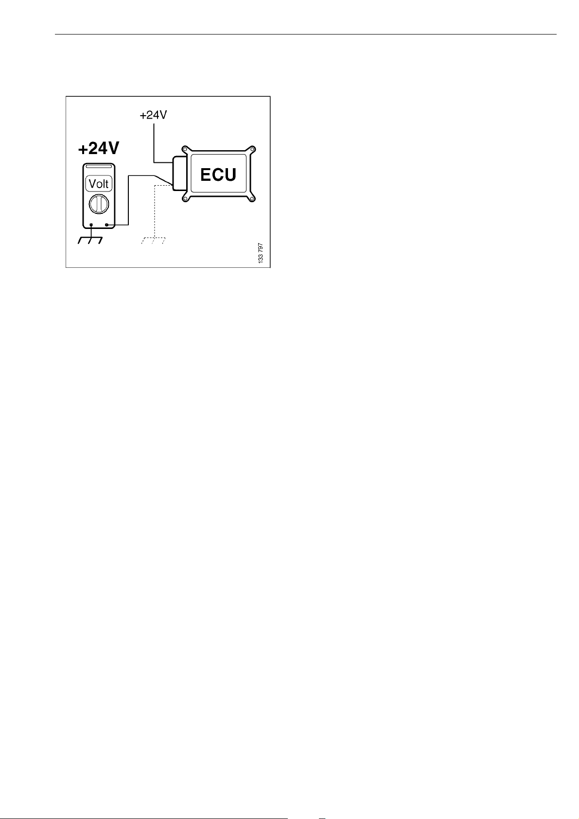
Figure 2b
Voltage drop across the earth cable. The cause is often in the connection to the chassis. The
multimeter should, of course, be connected to a safe earth. If the circuit is OK, the voltage drop
should be a maximum of 1 V.
16:07-01
©
Scania CV AB 2005, Sweden
65
Page 66
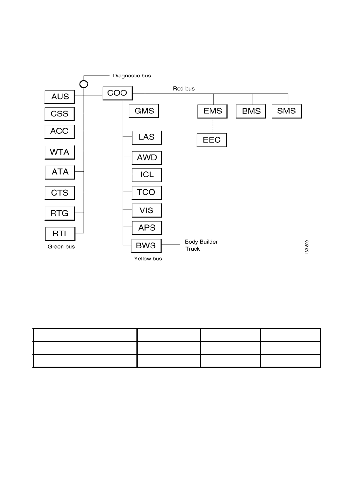
ECU chart
Location of the control units on the CAN buses
The above figure is an overview of the location of the control units on a basic specification vehicle
when the R series was introduced. The specification and location may vary between vehicles and
development stages.
Termination resistors in the CAN circuits
CAN Red Yellow Green
Termination resistor: 1 COO TCO*COO
Termination resistor: 2 EMS APS CTS*
There should be two termination resistors on each CAN bus. The control units in the table have
integrated termination resistors. *If one of the marked control units is missing in a specific vehicle
configuration, the integrated termination resistors in the control unit are replaced by a termination
resistor located in the CAN bus connector.
66
©
Scania CV AB 2005, Sweden
16:07-01
Page 67

Abbreviations
There are a large number of abbreviations for functions and components in the PRT series
documentation. The most commonly occurring abbreviations and what they stand for in English are
shown below.
• AHS:- Auxiliary Heater System
• AHS (CTS):- Clock and Timer System
• AHS (ATA):- Auxiliary Heater (Air to Air)
• AHS (WTA):- Auxiliary Heater (Water to Air)
• APS:- Air Processing System
• AUS:- Audio System
• BMS:- Brake Management System
• BWS:- Body Work System
• CCS:- Climate Control System
• CCS (ACC):- Automatic Climate Control System
• CSS:- Crash Safety System
• COO:- Coordinator System
• EMS:- Engine Management System
• GMS:- Gearbox Management System
• ICL:- Instrument Cluster System
• LAS:- Locking and Alarm System
• ROH:-Roof Hatch
• RTG:- Road Traffic informatics Gateway (FMS-interface)
• RTI:- Road Transport Informatics (PC on board)
• SMS:- Suspension Management System
• TCO:- Tachograph Systems
• VIS:- Visibility System
• POW:- Power supply
• INL:- Interior Light
• WIW:- Window Winder
• RDL:- Rear Diff Lock
16:07-01
©
Scania CV AB 2005, Sweden
67
Page 68

• ACL:- Automatic Central Lubrication
• MIH:- Mirror Heating
• MIA:- Mirror Adjustment
• ECU System:- A set of components such as sensors, actuators etc which includes an ECU
connected to the CAN bus
• DEC:- Discrete Electrical Circuit ( No ECU, or ECU not connected to the CAN bus)
• FC:- Function Category
• UF:- User Function
• UC:- User Case
• Scenario
• MSC:- Message Sequence Chart
• SIF:- System Internal Function
• (UF requiring no CAN information)
• DF:- Distributed Function
• (UF implemented by several systems)
• DSW:- Direct Signal Wiring
• (Conventional ECU interaction)
• SOPS:-Scania On-board Product Specification
68
©
Scania CV AB 2005, Sweden
16:07-01
Page 69

69
©
Scania CV AB 2005, Sweden
16:07-01
Page 70

70
©
Scania CV AB 2005, Sweden
16:07-01
Page 71

71
©
Scania CV AB 2005, Sweden
16:07-01
Page 72

72
©
Scania CV AB 2005, Sweden
16:07-01
 Loading...