

Page 1
program 96
©
Scania CV AB 1997-05:2
Issue 2
en
Part No.
1 588 468
Industrial & Marine Engines
01:01-02
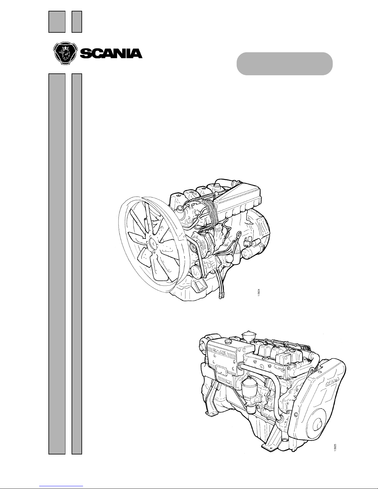
Work Description - 9-series engine
Industrial and Marine engines
Page 2
2
©
Scania CV AB 1997-05:2 01:01-02
Program 96
Contents
.................................... Page ....................................Page
Cylinderhead ...........................3
Valveclearance........................5
Compression ..........................6
Removing.............................8
Dismantling ...........................9
Checking,changingandmachining.........9
Assembly............................17
Fitting...............................17
Turbocharger...........................19
General..............................20
Measuring radial clearance and
axialclearance........................21
Iftheturbochargerisnotworking.........22
Changingtheturbocharger...............23
Pistonsandcylinderliners.................24
Removaloflooseringincylinderliner.....26
Removal and dismantling of piston and
connecting rod ........................26
Assembling piston and connecting rod .....29
Removingcylinderliner ................30
Fittingcylinderliner ...................35
Fitting piston and connecting rod .........36
Flywheel and flywheel housing............. 38
Removingflywheel....................40
Removing and fitting flywheel housing.....42
Fittingflywheel.......................43
Timinggear ............................44
Crankshaftseal........................46
Timinggearcover......................48
Intermediategear ......................50
Crankshaftgear........................51
Camshaftgear.........................52
Camshaft.............................53
Crankshaft............................55
Lubricationsystem.......................57
Oilcooler ............................57
Oilcleaner............................59
Oilpump.............................63
Liftingtheengine........................64
Specifications...........................65
Generalinformation....................65
Cylinderhead.........................65
Turbocharger..........................67
Pistonsandcylinderliners ...............67
Flywheel and flywheel housing ...........68
Timinggear...........................69
Lubricationsystem.....................71
Specialtools............................73
Page 3

01:01-02
©
Scania CV AB 1997-05:2 3
Program 96
Cylinder head
1. Cylinder head
2. Valve guide
3. Valve guide
4. Valve seat ring
5. Valve seat ring
6. Core plug
7. Core plug
8. Seal (not standard)
9. Intake valve
10. Exhaust valve
11. Valve spring collar
12. Valve spring
13. Valve spring
14. Valve spring collar
15. Collet
16. Valve stem cap
17. Bearing bracket
18. Rocker arm
19. Bushing
20. Adjusting screw
21. Hexagon nut
22. Retaining ring
23. Spiral pin
24. Bolt
25. Flange bolt
26. Cylinder head gasket
27. Pin
Page 4
4
©
Scania CV AB 1997-05:2 01:01-02
Program 96
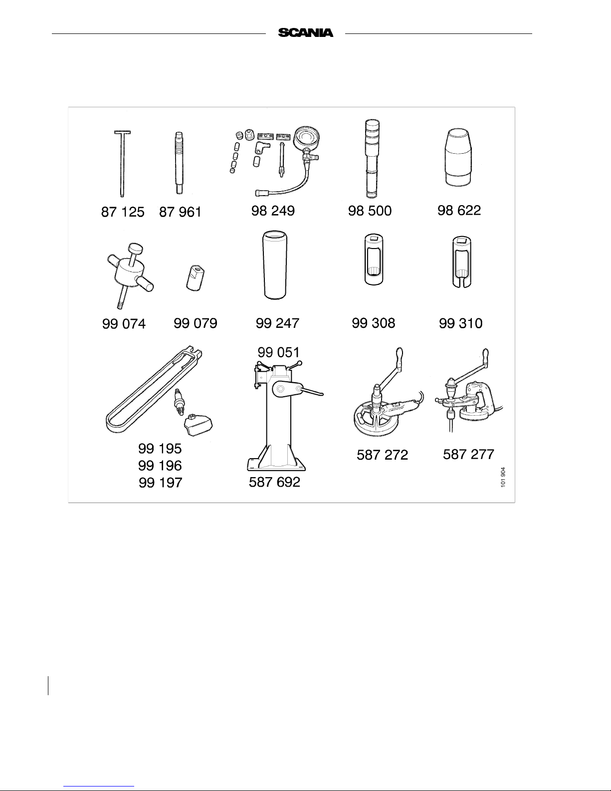
Special tools
87 125 Extractor
87 961 Drift
99 246 Drift
98 249 Compression tester
98500 Shank
98 503 Drift
98 622 Press drift
99 051 Fixture
99 074 Impact drift
99 079 Injector extractor
99 247 Assembly drift
99 195 Valve spring compressor, com-
plete
99 308 Sleeve for injector
99 310 Sleeve
587 272 Cylinder liner cutter with grooving
tool
587 277 Valve seat cutter
587 692 Engine stand
Page 5
01:01-02
©
Scania CV AB 1997-05:2 5
Program 96
Valve clearance
Checking and adjusting
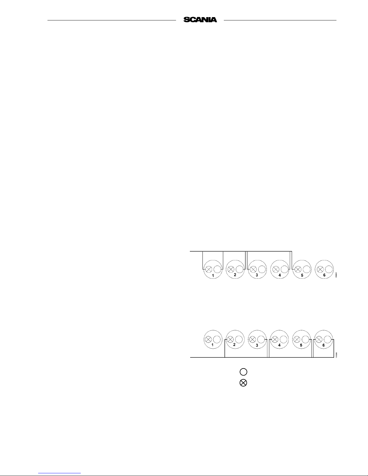
Check valve clearance. The clearance for intake
valves should be 0.45 mm and the clearance for
exhaust valves should be 0.80 mm when the
engine is cold.
Adjustment can be carried out in one of the following ways:
A. Adjust both valves in each cylinder starting
with No. 1 cylinder at TDC after compression.
Turn the crankshaft 1/3 turn at a time and adjust
valves in injection sequence:
1-5-3-6-2-4
B. Set No. 1 cylinder a t precisely TDC after compression. The following valves can now be
adjusted:
cylinder 1 intake and exhaust
cylinder 2 intake
cylinder 3 exhaust
cylinder 4 intake
cylinder 5 exhaust
Turn the crankshaft precisely one revolution so
that TDC for No. 6 cylinder is set. The remaining
valves can now be adjusted:
cylinder 2 exhaust
cylinder 3 intake
cylinder 4 exhaust
cylinder 5 intake
cylinder 6 exhaust and intake
Intake valve
Exhaust valve
Page 6

6
©
Scania CV AB 1997-05:2 01:01-02
Program 96
Compression
Measuring
The compression tester is used to quickly and simply check wear and damage to primarily the cylinder head valves, but also to cylinder liners and
piston rings.
Measurements are only intended for comparison
between cylinders. Lower compression in one or
several cylinders is a sign of abnormal wear or
damage.
By using various accessories, the compression
tester can be used for several engine types.
1. Lock the stop lever in the stop position.
2. Clean around injectors. Detach delivery pipes
and leak-off pipes from all injectors.
Note Fit protective caps on the delivery
valve holders in the injection pump,
on the delivery pipes and the injectors to protect them from dirt.
3. Undo and remove the injectors and copper
washers.
4. Turn the engine over several times using the
starter motor to remove any loose soot in the
cylinders.
1. Pressure gauge
2. Zeroing valve
3. Flexible metal hose
4. Measuring rod, complete
5. End sleeve, diameter 21 mm
6. Spacing sleeve with guide lug
7. Spacing sleeve with collar
8. Spacing sleeve, length 6 mm
9. Spacing sleeve, length 19 mm
10. Spacing sleeve, length 25 mm
11. Spacing sleeve, length 38 mm
12. Cap nut
13. Threaded socket nut
14. Large yoke
15. Small yoke
Compression tester 98 249
Page 7
01:01-02
©
Scania CV AB 1997-05:2 7
Program 96
5. Connect the compression tester in the injec-
tion aperture in one of the cylinders. Copper
washer 16 should be used between the compression tester and the bottom of the injector
aperture.
6. Turn the engine over using the starter motor
and read the pressure gauge. Note the result.
7. Zero the pressure gauge by pressing zeroing
button 2.
8. Move the compression tester to the next cyl-
inder and proceed as in points 7-9.
9. Evaluate the readingsand assess what further
measures need to be taken on the engine.
Cleaning the measuring rod
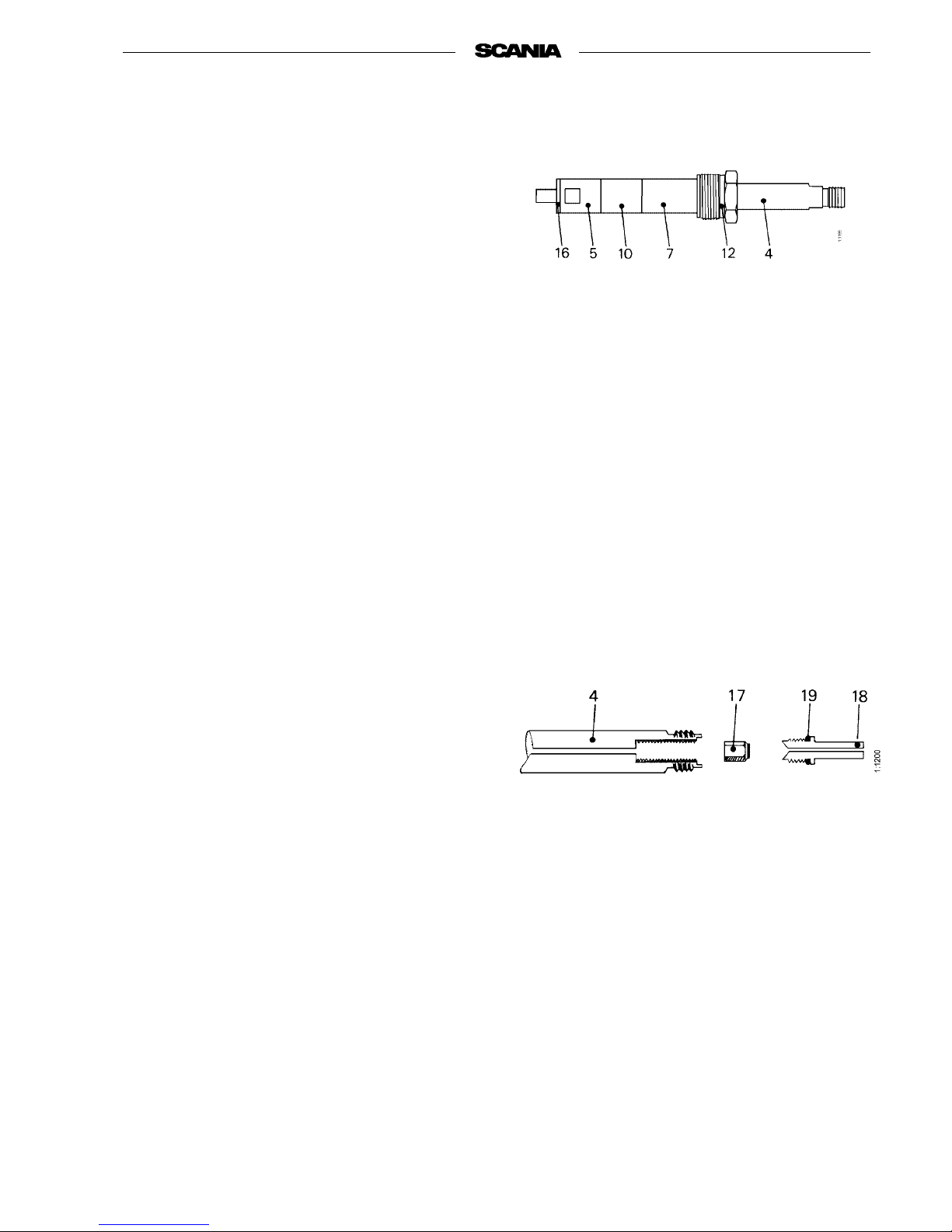
Measuringrod4hasacheckvalvewhich,inthe
case of leakage, should be cleaned as follows:
1. Unscrew valve seat 18.
2. Remove all soot from valve 17 and valveseat
18. Do not scratch the sealing surfaces. Use
compressed air to clean the inside of measuring rod 4.
3. Assemble the parts. Makesure that O-ring 19
is not damaged. Fully screw on valve seat 18
so that it seals against measuring rod 4.
4 Measuring rod
5 End sleeve, diameter 21 mm
7 Spacing sleeve with collar
10 Spacing sleeve, L = 25 mm
12 Cap nut (use socket 99 308 for
tightening)
16 Copper washer
4Measuring rod
17 Valve
18 Valve seat
19 O-ring
Measuring rod, complete
Measuring rod
Page 8
8
©
Scania CV AB 1997-05:2 01:01-02
Program 96
Removing
1. Remove the intake manifold, exhaust mani-
fold and turbocharger.
2. Remove the coolant manifold.
3. Remove the delivery pipes. Protect the con-
nections on the injection pump and injectors
with plastic plugs.
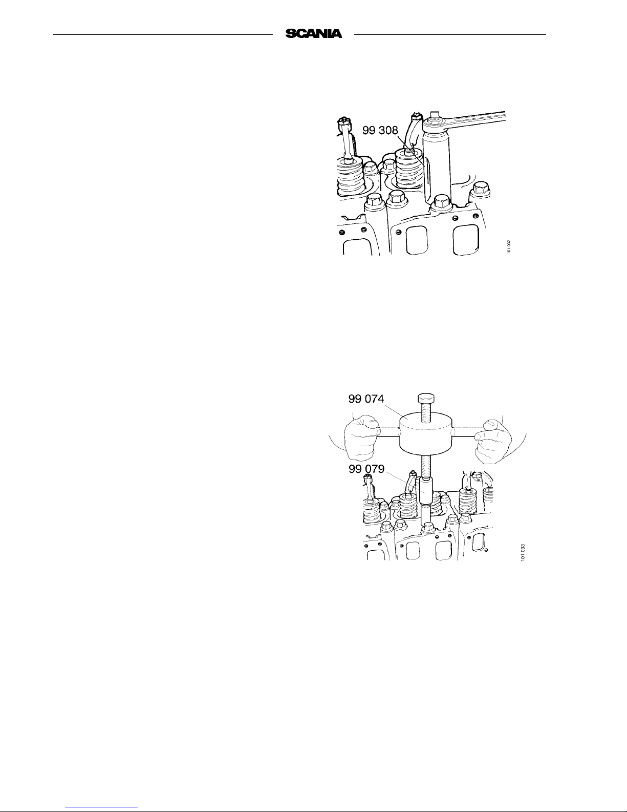
4. Undo the injector nut using socket 99 308.
5. Extract the injectors using tools 99 079 and
99 074. Remove the copper washers using
tool 87 125.
6. Insert protective plugs in the ends of the
delivery pipes and fit protective caps on the
injectors and injection pump.
Note All parts in the valve mechanism
should be refitted in the same positions. For this reason, mark all parts
that are removed.
7. Unscrew the rocker arm mechanism.
8. Lift out the pushrods.
9. Remove the cylinder head bolts. Lift off the
cylinder head.
Place it on a bench on a soft surface to avoid
damage to the mating surface.
Page 9

01:01-02
©
Scania CV AB 1997-05:2 9
Program 96
Dismantling
1. Remove the valve stem caps.
2. Extract collets, valve spring collars, springs
and valves. Use tools 99 195 and 99 196 to
compress the valve springs so that the collets
can be removed.
3. Place the valves in a stand so that they can be
refitted in the same cylinder head. Mark the
cylinder heads if several are removed at the
same time.
Checking, changing and machining
Valve stem seal (not standard)
Changing
1. Remove the valve stem seal.
2. Fit a new seal with tool 99 247.
Note Do not hammer on the seal so hard
that the valve guide is displaced.
Valves
Checking and machining
- Check dimension A on all valves.
- Machine the valves in a valve grinder.
Intake 19.5°and exhaust 44.5°.
See specifications.
Minimum dimension A for
ground valve
Intake 3.0 mm
Exhaust 1.7 mm
Page 10

10
©
Scania CV AB 1997-05:2 01:01-02
Program 96
New exhaust valve and new valve seat ring
New intake valve and new valve seat ring
New exhaust valve and valve seat ring
machined to maximum. Surfaces at arrows
aligned
New intake valve and valve seat ring
machined to maximum
Page 11
01:01-02
©
Scania CV AB 1997-05:2 11
Program 96
Valve seats
Changing
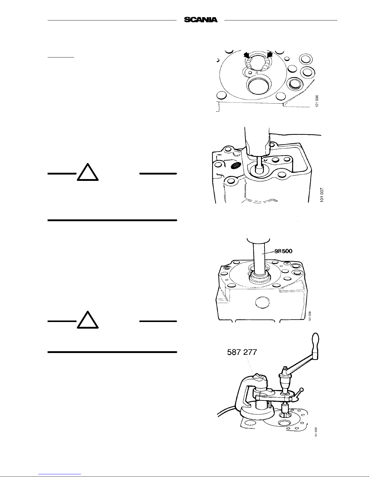
1. Remove valve seat rings. Use an old valve
which has been machined so that the diameter of the head is slightly smaller than the
inside diameter of the seat.
2. Place the valve in position and weld it all
round using an arc welder. Cool with water.
Turn the cylinder head over and tap the valve
stem so that valve and seat ring fall out.
Wear protective goggles!
WARNING!
!
Always turn the cylinder head with the
underside down when the valve seat ring
is being tapped out. Otherwise, there is a
risk of loose swarf causing injury.
3. Press in new valve seat rings. Use drift
98 503 and shank 98 500. Cool the drift and
valve seat to about -80 °C in dry ice or liquid
air. The rings must be pressed in very
quickly.
WARNING!
!
Take care when using the above coolants
and cooled parts. Danger of frostbite.
Oversize valve seat rings can be fitted if the valve
seat ring position has been damaged. The seat
must then be machined using tool 587 277.
Page 12

12
©
Scania CV AB 1997-05:2 01:01-02
Program 96
Machining
Machining dimensions and oversize valve seat
rings, see Specifications.
1. Check that the contact surface and magnetic
foot are smooth and clean. Clean valve bushings.
2. Select the largest spindle which easily goes
into the valve guide.
Fit the guide spindle and turn the feed screw
to its upper position.
3. Select and fit cutter.
4. Undo the speed lock and movethe pivotplate
to the upper position using the adjusting
screw.
Page 13

01:01-02
©
Scania CV AB 1997-05:2 13
Program 96
5. Set the pointer on the cutter using a valve.
6. Set the cutter.
7. Disconnect the magnet (position 2). Insert the
guide spindle in the valve bushing. Adjust the
pivot plate so that the gap between the cutter
and the valve seat is about 1 mm. Carefully
centre the tool.
8. Connect the magnet (position 1).
9. Secure speed lock. Check that crank is easy
to turn. If not, repeat centring.
10. Cut valve seat bycranking clockwise and turn-
ing the feed screw at the same time. Never
crank anticlockwise. The cutter may break.
Lubricate with cutting oil while working.
11. When the valve seat surface is finished,
reduce cutting pressure by cranking 2-3 turns
without feeding. Continue cranking and turn
the feed screw anticlockwise. The valve seat
cutter is now ready for the next valve seat.
Page 14

14
©
Scania CV AB 1997-05:2 01:01-02
Program 96
Rocker arms
Changing bushing
1. Remove the retaining ring.
2. Remove rocker arm from support bracket.
3. Press bushing out of rocker arm using drift
98 622.
4. If wear is light, the surface of the rocker arm
which presses against the valve stem cap can
be adjusted using a grinding machine.
5. Turn the slit in the bushing up. Press bushing
into rocker arm using drift 98 622.
6. Drill the oil hole in the bushing to the same
diameter as the oil hole in the rocker arm.
7. The bushing should then be finely worked.
See specifications.
8. Lubricate the bushing using engine oil before
the rocker arm is placed on the support
bracket.
Page 15
01:01-02
©
Scania CV AB 1997-05:2 15
Program 96
Valve guides
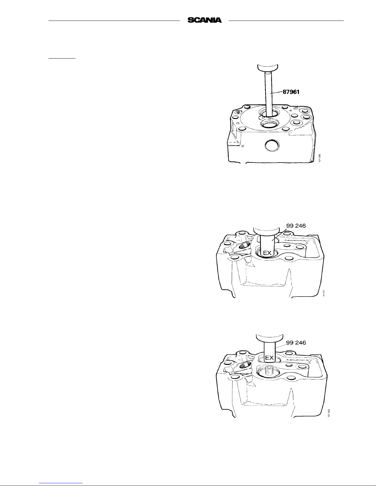
Changing
1. Press out valve guides using drift 87 961.
2. Press in new valve guides using drive 99 246
(exit). Press down the guide as far as the drift
will allow, i.e. until it is against the spring
seat in the cylinder head.
Page 16

16
©
Scania CV AB 1997 01:01-02
Program 96
Cylinder head
Checking and machining the sealing surface
against cylinder block.
Cylinder head is checked for cracks and other
defects. The sealing surface against the cylinder
block is checked against a surface plate. If the sealing surface must be machined, cylinder head height
after machining must not be less than 114.4 mm.
After machine flat, new sealing grooves for the
gasket must be milled.
Use tool 587 272.
Also machine the recesses for the sealing rings.
Depth 0.9-1.1 mm.
Sealing groove in cylinder head
01:01-02
Page 17
01:01-02
©
Scania CV AB 1997 17
Program 96
Assembly
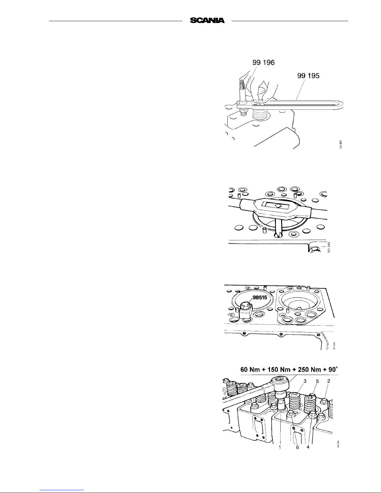
1. Thoroughly lubricate all parts before assembly.
2. Insert the valve stem in the guide. (Fit the
valve stem seal, if any.)
3. Fit the lower guide washer, the two valve
springs and the upper guide washer.
4. Compress springs using tools 99 195 and
99 196 and fit collets.
5. Fit valve stem caps.
Fitting
1. Clean the cylinder head bolt holes in the
block using an M16 tap.
Check the liner height, see Pistons and cylin-
der liners.
2. Fit a new gasket.
3. Fit the cylinder head and ensure that the
guide pins fit in the holes.
4. Change bolts having three centre-punch
marks on the head for new ones.
5. Lubricate the threads on the cylinder head
bolts and the surface under the head.
6. Tighten the bolts in the order given in the fig-
ure and in three stages + 90 degrees as follows:
• Tighten all bolts to 60 Nm
• Tighten all bolts to 150 Nm
• Tighten all bolts to 250 Nm
• Finally tighten all bolts 90 degrees
7. Mark all bolts with a fresh centre-punch
mark.
(Except new bolts.)
Page 18
18
©
Scania CV AB 1997 01:01-02
Program 96
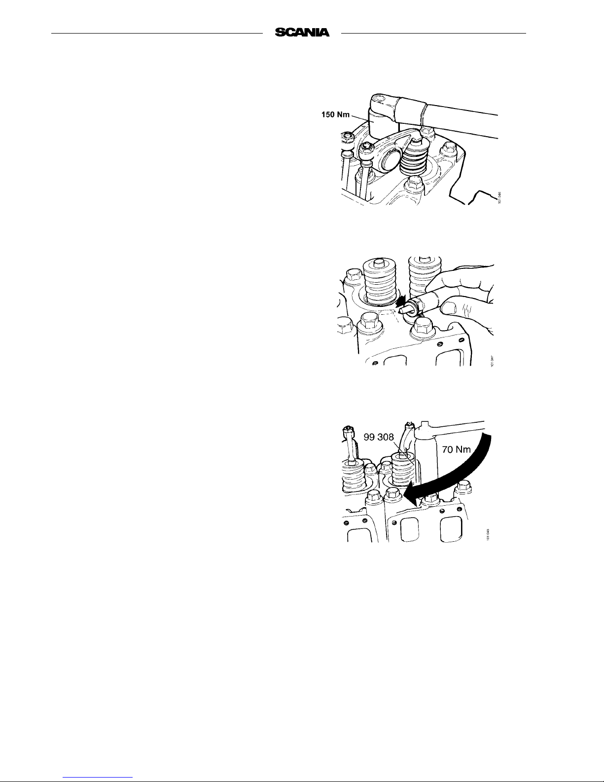
8. Fit the pushrods and rocker arm mechanism.
Tighten the rocker arm mechanism bolts to
150 Nm.
9. Check valve clearance as described in Valve
clearance, checking and adjusting on page 5.
10. Check that no old seal remainsin the injector
hole. Fit the injectors complete with new
seals.
11. Tighten the injectors to 70 Nm using tool
99 308.
12. Fit the rocker covers and tighten them to
20 Nm.
13. Fit delivery pipes and tighten to 20 Nm using
socket 99 310. Fit leak-off pipes, coolant
manifold, intake manifold and exhaust manifold with new gaskets and seals.
14. If the exhaust pipe has been removed and dis-
mantled, joints should be lubricated using
lubricant 561 205 when reassembling.
Page 19

01:01-02
©
Scania CV AB 1997 19
Program 96
Turbocharger
1. Lubrication oil pipe
2. Ferrule
3. Union nut
4. Straight union
5. Gasket
6. Gasket
7. Hexagon socket screw
8. Lubrication oil return pipe
9. Gasket
10. Flange bolt
11. Hose
12. Hose clip
13. Elbow union
14. Clamp
15. Clamp
16. Flange bolt
17. Flange bolt
18. Turbocharger
587 107 Out-of-true indicator
587 250 Measuring stand
98 075 Dial gauge
587 025 Filter wrench
Special tools
Page 20

20
©
Scania CV AB 1997 01:01-02
Program 96
General
Note When working on the turbocharger,
cleanliness is extremely important.
Oil inlet and outlet connections must
never be left unprotected. A foreign
body in the bearing housing can
quickly lead to total breakdown.
Oil leakage
A clogged air cleaner causes vacuum in the intake
line to become excessive. If this occurs there is a
riskthatoilmistwillbedrawnoutfromthebearing
housing into the compressor and then on into the
engine.
If the seal on the turbine side is worn, exhaust gas
will be blue when idling.
If the oil outlet pipe from the turbocharger is damaged, there is a danger of oil being forced out
through the seals due to lubrication oil pressure.
Foreign bodies
Foreign bodies such as grains of sand or metal
swarf in the turbine or compressor will destroy the
impeller vanes. This leads to imbalance and bearing wear. Engine output drops and, if operation
continues, there will be a risk of damage due to
overheating as the air supply drops. This type of
overheating cannot be observed on the coolant
temperature gauge.
Note Never attempt to straighten a dam-
aged vane. It will usually break when
in operation and cause turbocharger
breakdown and engine damage.
Air and exhaust leakage
Even very tiny leaks in the line between air cleaner
and turbocharger cause deposits of dirt on the compressor wheel. Charge pressure then drops, resulting in higher exhaust temperature and smoke. Wear
on the engine also increases.
Exhaust leaks between cylinder head and turbo
also result in low charge pressure.
Charge pressure
Note that low charge pressure does not necessarily
mean that the turbocharger is faulty. Low pressure
may be caused by such things as a clogged air filter, leakage in the intake or exhaust lines, an incorrectly adjusted throttle control, faulty injectors,
defective injection pump or faulty smoke limiter.
Cleaning compressor wheel
Low charge pressure can be caused by a dirty compressor wheel. Remove the compressor cover.
Wash the compressor wheel using white spirit and
a brush. Fit the compressor cover and read the
charge pressure.
Note The compressor wheel must not be
removed from the shaft. This could
cause imbalance when refitted.
Page 21
01:01-02
©
Scania CV AB 1997 21
Program 96
Measuring radial clearance and
axial clearance
Measuring radial clearance and axial clearance
does not usually give any indication of the
remaining service life of the turbocharger.
If the turbocharger appears to be functioning
poorly or is making a noise, measuring charge
pressure or measuring radial and axial clearance
may indicate that the turbocharger is defective.
For measuring axial and radial clearance, the turbocharger can be removed and bolted to a steel
plate to which the magnetic dial gauge stand can
also be attached.
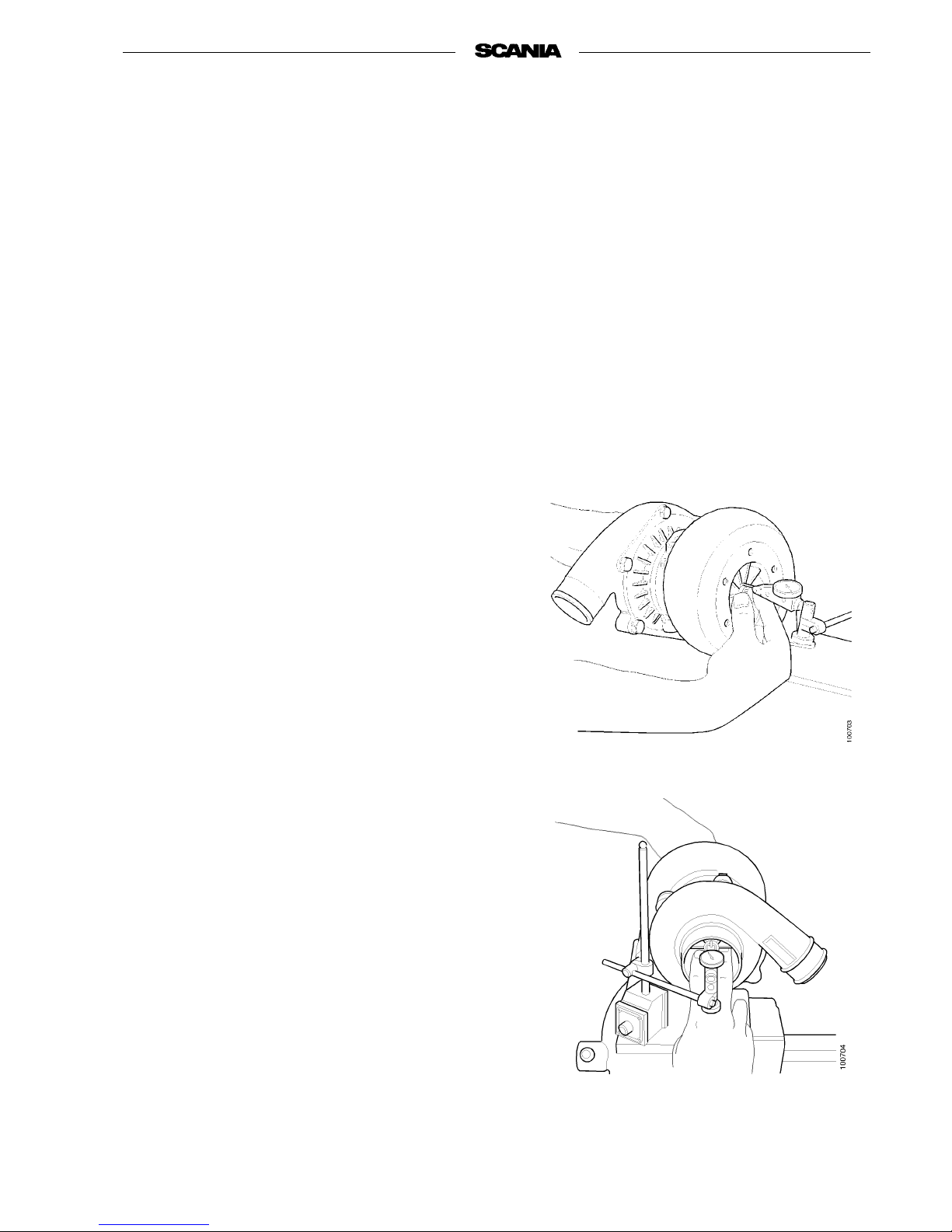
Radial clearance
Take readings on both turbine wheel and compressor wheel.
1. Place the point of the dial gauge against the
turbine wheel and compressor wheel.
2. Pull both ends of the shaftup. Take a reading.
3. Press both ends of the shaft down. Take a
reading. The difference between readings is
radial clearance.
4. Repeat measurements three times on each
side.
5. If any wheel rubs against the housing, despite
radial clearance being within tolerance, the
turbocharger should be changed.
Measuring turbine wheel radial clearance.
Measuring compressor wheel radial
clearance
Page 22

22
©
Scania CV AB 1997 01:01-02
Program 96
Axial clearance
1. Place the point of the dial gauge against the
end of the shaft.
2. Press the shaft forwards and backwards and
read the dial at the end positions. The difference between readings is axial clearance.
3. Repeat measurements three times.
Wear limits for Holset:
Radial clearance 0.329-0.501 mm
Axial clearance
(after running-in) 0.038-0.093 mm
If the turbocharger is not working
1. Check that there is no leakage nor any loose
objects in the linebetween theair cleaner and
turbocharger.
2. Check that there are no loose objects in the
exhaust manifold or intake manifold.
Change the charge air cooler.
3. Check that all valves are intact.
4. Check the lubrication oil return pipe from the
turbocharger for blockage or deformation.
5. Check the oil delivery pipe to the turbo-
charger for any blockage, deformation and
leakage under pressure.
6. Check the condition and part number of the
oil filter.
7. Check that the air filter is not blocked and
that there are no other reasons for the abnormal increase of vacuum in the intake system.
8. Check that engine output is correct. Exces-
sively high output reduces the life of the
turbo.
9. Check that the exhaust brake, if fitted, works
correctly.
Page 23

01:01-02
©
Scania CV AB 1997 23
Program 96
Changing the turbocharger
Note When changing the turbocharger,
all gaskets and the oil filter must be
changed and the centrifugal cleaner
cleaned.
Removing
1. Detach exhaust pipe, induction pipe and
charge air cooler pipe from the turbocharger.
2. Detach then oil supply and return lines.
3. Unscrew the bolts in the turbocharger mount-
ing and remove the turbocharger.
Fitting
1. Check the connecting flange on the exhaust
manifold to ensure that no remnants of the
old gasket are still present.
2. Fit a new gasket and bolt on a new turbo-
charger. Lubricate theexhaust manifoldbolts
with temperature resistant lubricant, Part No.
561 205. Tighten to 40 Nm.
3. Connect oil supply and return lines.
4. Connect charge air pipe, induction pipe and
exhaust pipe.
5 Lock the stop lever in the stop position and
turn the engine over by means of the starter
motor for at least 30 seconds so that the lubricating oil reaches the turbocharger.
On engines with a fuel shut-off valve, this
valve should be disconnected while the
engine is being turned over.
6. Start the engine and check that there is no
leakage.
Page 24
24
©
Scania CV AB 1997 01:01-02
Program 96
Pistons and cylinder liners
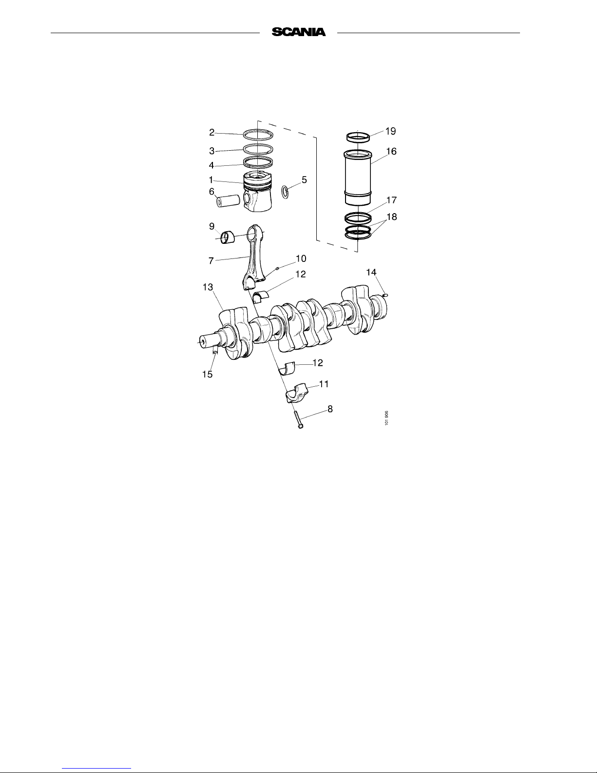
1. Piston
2. Compression ring
3. Compression ring
4. Oil scraper ring
5. Retaining ring
6. Gudgeon pin
7. Connecting rod
8. Flange bolt
9. Bushing
10. Pin
11. Bearing cap
12. Big-end bearing
13. Crankshaft
14. Pin
15. Key
16. Cylinder liner
17. Seal
18. O-ring
19. Loose ring
Page 25
01:01-02
©
Scania CV AB 1997 25
Program 96
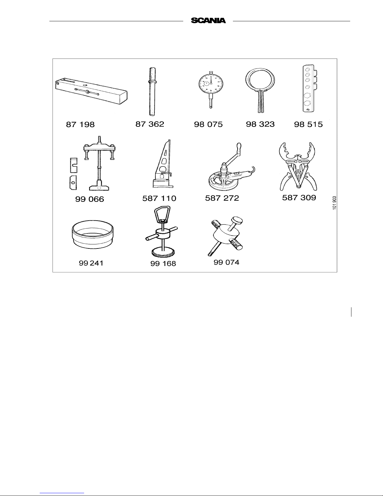
Special tools
87 198 Straight edge for dial gauge
87 362 Drift
98 075 Dial gauge
98 323 Piston ring compressor
98 515 Pressing tool
99 066 Puller for cylinder liner
99 074 Impact drift
99 241 Assembly tool
99 168 Dismantling tool
587 110 Connecting rod tester
587 272 Cylinder liner cutter
587 309 Piston ring expander
Page 26
26
©
Scania CV AB 1997 01:01-02
Program 96
Removal of loose ring in cylinder
liner
If the loose ring is so firmly in place that it cannot
be removed by hand, proceed as follows:
1. Remove cylinder head and oil sump.
2. Rotate the crankshaft until the piston is at
BDC.
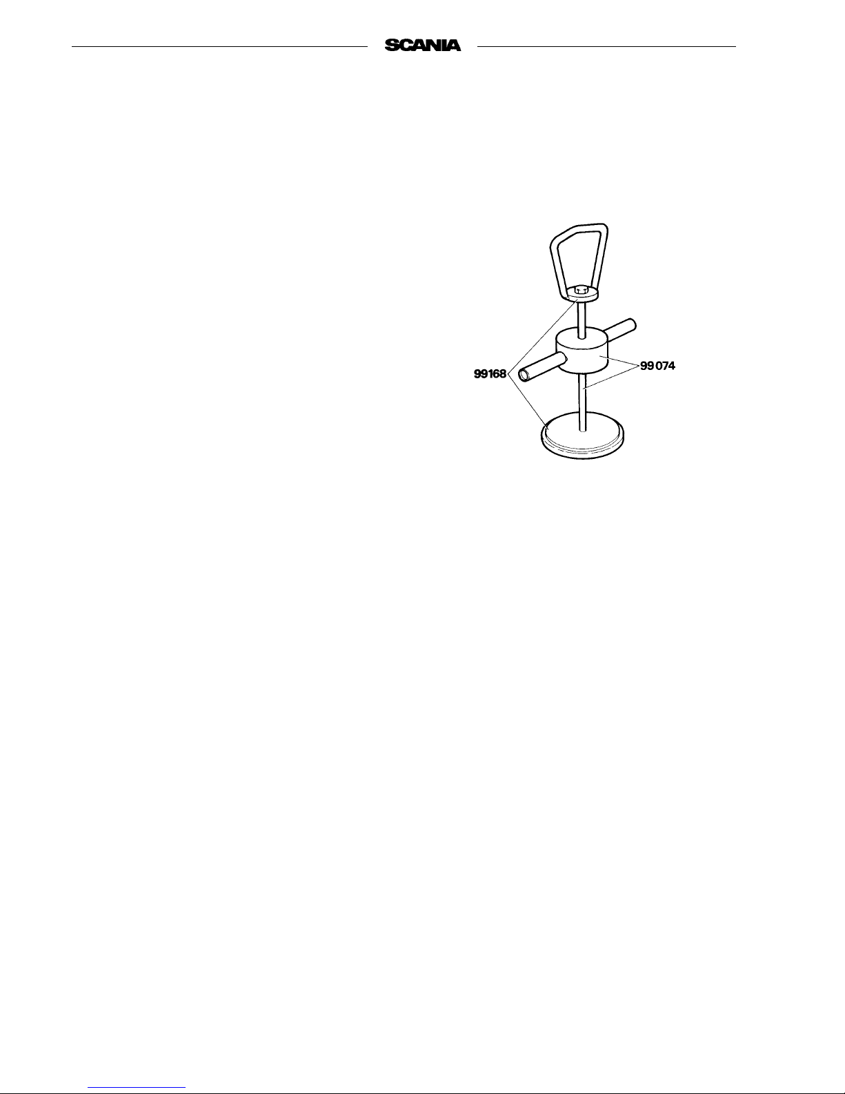
3. Fit tension lugs 98 515 to the edge of the cyl-
inder liner so that the liner cannot be pulled
out of position.
4. Place plate 99 168 on the piston crown.
5. Press a piston ring into the liner until it is
below the loose ring.
6. Fit handle 99 168 on impact drift 99 074. If it
proves difficult to fit the bolt in the handle,
the bolt head canbe grounddown slightlybut
without weakening the bolt.
7. Screw the bolt into the plate.
8. Pull up the plate so that it abuts against the
pressed-in piston ring.
9. Drive out the loose ring using the impact
drift.
Removing and dismantling pi ston
and connecting rod
1. Remove the piston cooling nozzles in the cyl-
inder block.
Note The piston cooling nozzle must not
be damaged.
If the jet of oil does not strike the
piston in the right place, there could
be a danger of engine breakdown.
Damaged nozzles must be changed.
Page 27
01:01-02
©
Scania CV AB 1997 27
Program 96
2. Remove the bearing cap and bearing halves.
Protect the oilway in the crankshaft using
tape, for instance, wound with the adhesive
side out.
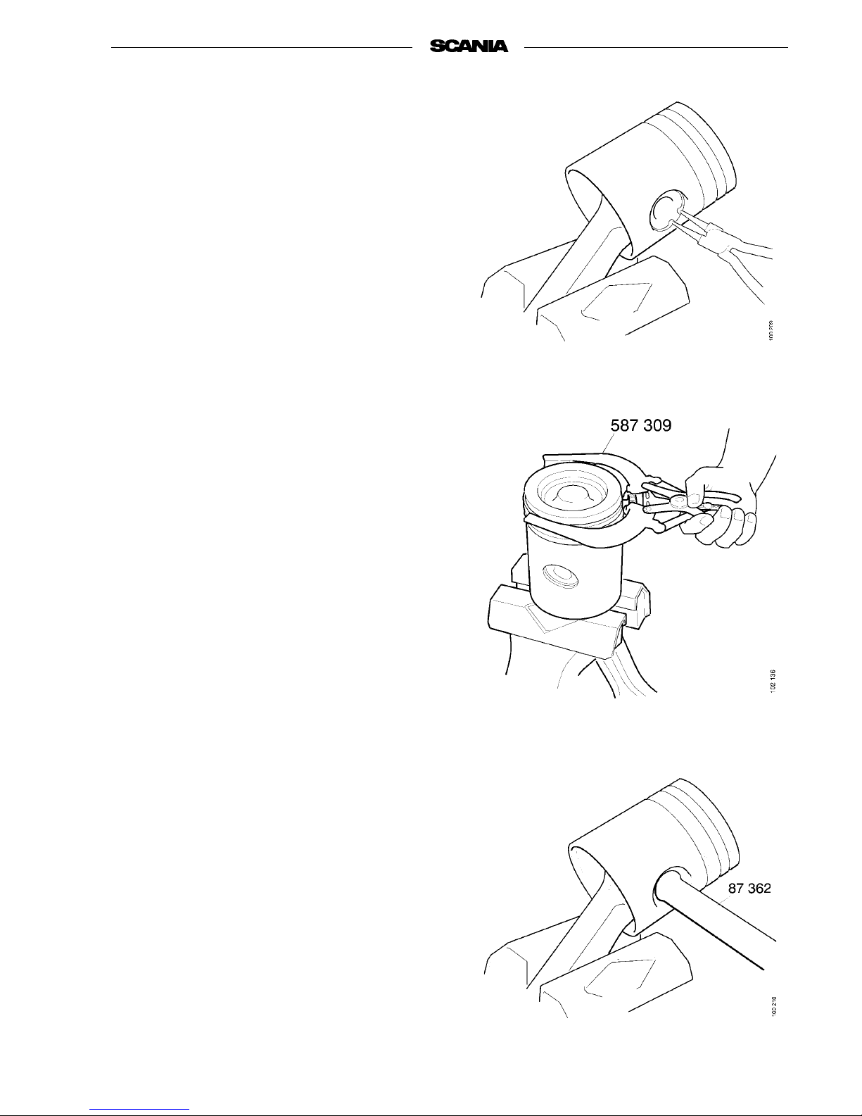
3. Drive out piston and connecting rod.
4. Place the connecting rod in a vice with soft
jaws. Remove the gudgeon pin retaining
rings.
5. Remove the piston rings using tool 587 309.
Be careful not to scratch the piston skirt with
the piston rings.
When cleaning graphited pistons in a machine,
the graphiting may disappear. This does not
matterwhentheyhavebeenusedforsome
time. However, new pistonsshould bewashed
carefully using white spirit, for instance.
Note Always check the connecting rods
in cylinders which have seized,
been filled with water or in which
the valve has broken. Bent connecting rods must not be straightened.
6. Push out the gudgeon pin using drift 87 362.
Page 28
28
©
Scania CV AB 1997 01:01-02
Program 96
Checking connecting rods
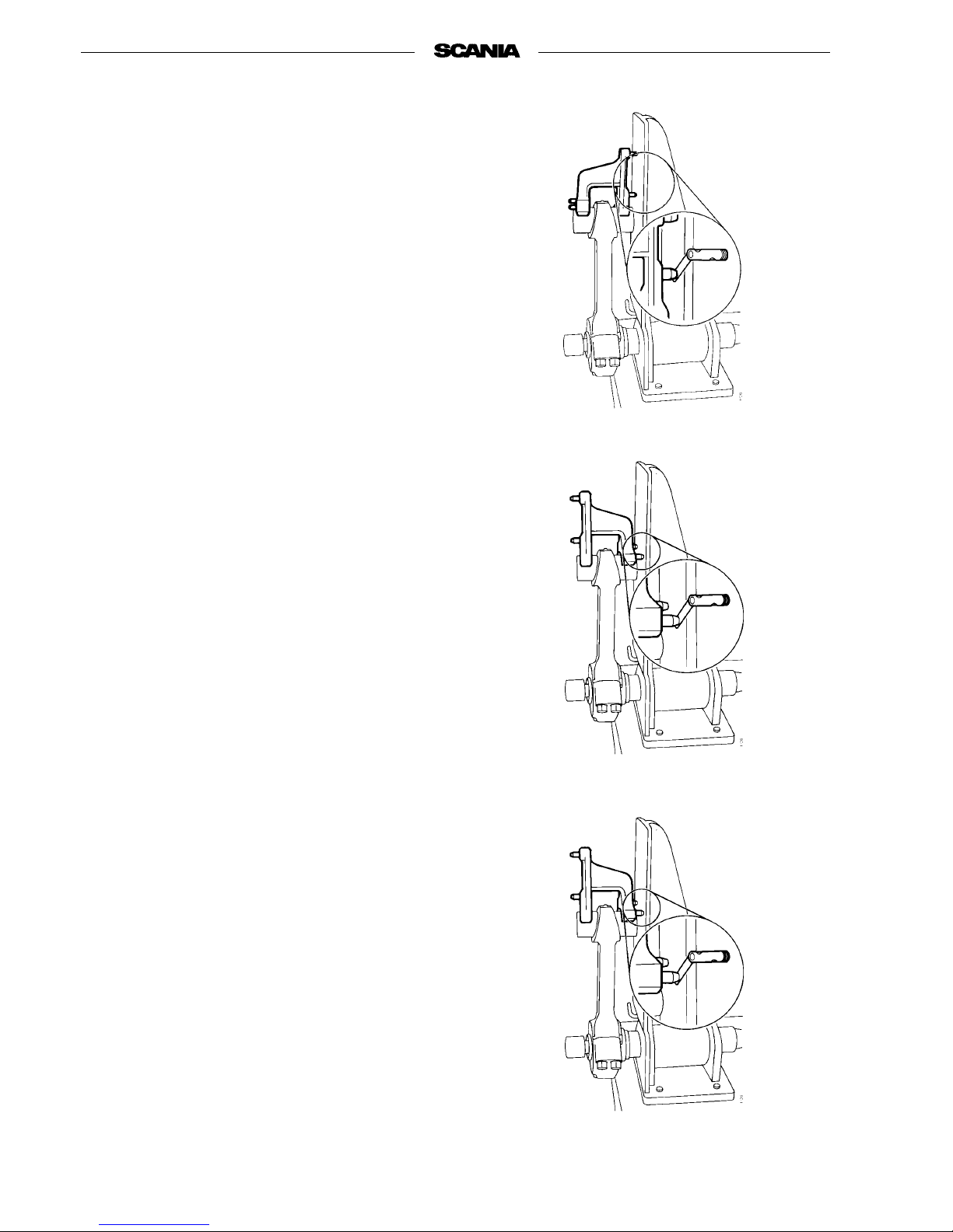
Check connecting rods using tool 587 110. Proceed as follows:
1. When the gudgeon pin bushing has been
checked, insert thebearing capas marked and
tighten the bolts with full torque.
2. Mount the connecting rod in the tool using
the expander and place the gudgeon pin in its
bushing. Then place indicator studs on the
gudgeon pin.
3. Check whether the connecting rod is twisted,
with the indicator studs horizontal.
4. Check whether the connecting rod is bent,
with the indicator studs vertical.
- The distance between theindicator studs on the
tool shown here is 75 mm
- The distance between one of the indicatorstuds
and the surface being measured must not be
more than 0.1 mm, measured using this tool.
- Check with a feeler gauge.
- Also check whether the connecting rod is bent
into an S shape. Do this by measuring the distance between the outer side of the connecting
rod bushing and the flat surface on the tool.
- Turn the connecting rodround andmeasure the
corresponding dimension.
- The difference should be no more than 0.6 mm.
Checking whether the connecting rod is
twisted
Checking whether the connecting rod is bent
Checking whether the connecting rod is bent
into an S shape
Page 29
01:01-02
©
Scania CV AB 1997 29
Program 96
Assembling piston and connecting
rod
1. Clean the piston and its ring grooves care-
fully without scratching the sides of the ring
grooves. The oil holes in the piston should be
cleaned using a suitable drill.
2. Check that the axial clearance of the other
piston ring does not exceed the permitted
value (0.25 mm).
See specifications.
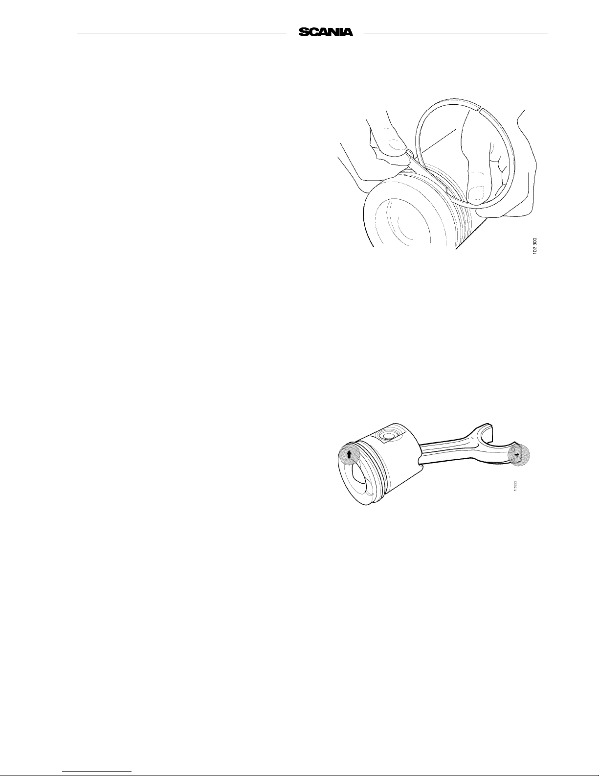
3. Fit the piston rings using tool 587 309.
The oil scraper ring has an expander.
Piston rings marked TOP should be turned
with TOP up.
4. Oil all bushings and the gudgeon pin before
assembly.
5. Clamp the connecting rod in a vice with soft
jaws. Turn it so that the cylinder number
marking faces outwards.
6. Fit one of the retaining rings in the piston.
Heat the piston to 100 °C and place it on the
connecting rod with the arrow pointing as
shown in the figure.
7. Push in the gudgeon pin using drift 87 362.
8. Fit the second retaining ring.
Page 30
30
©
Scania CV AB 1997 01:01-02
Program 96
Removing cylinder liner
1. Mark the liners with the numbers 1-6. Mark-
ing is essential to make it possible to fit the
liners in the same place and same position as
previously.
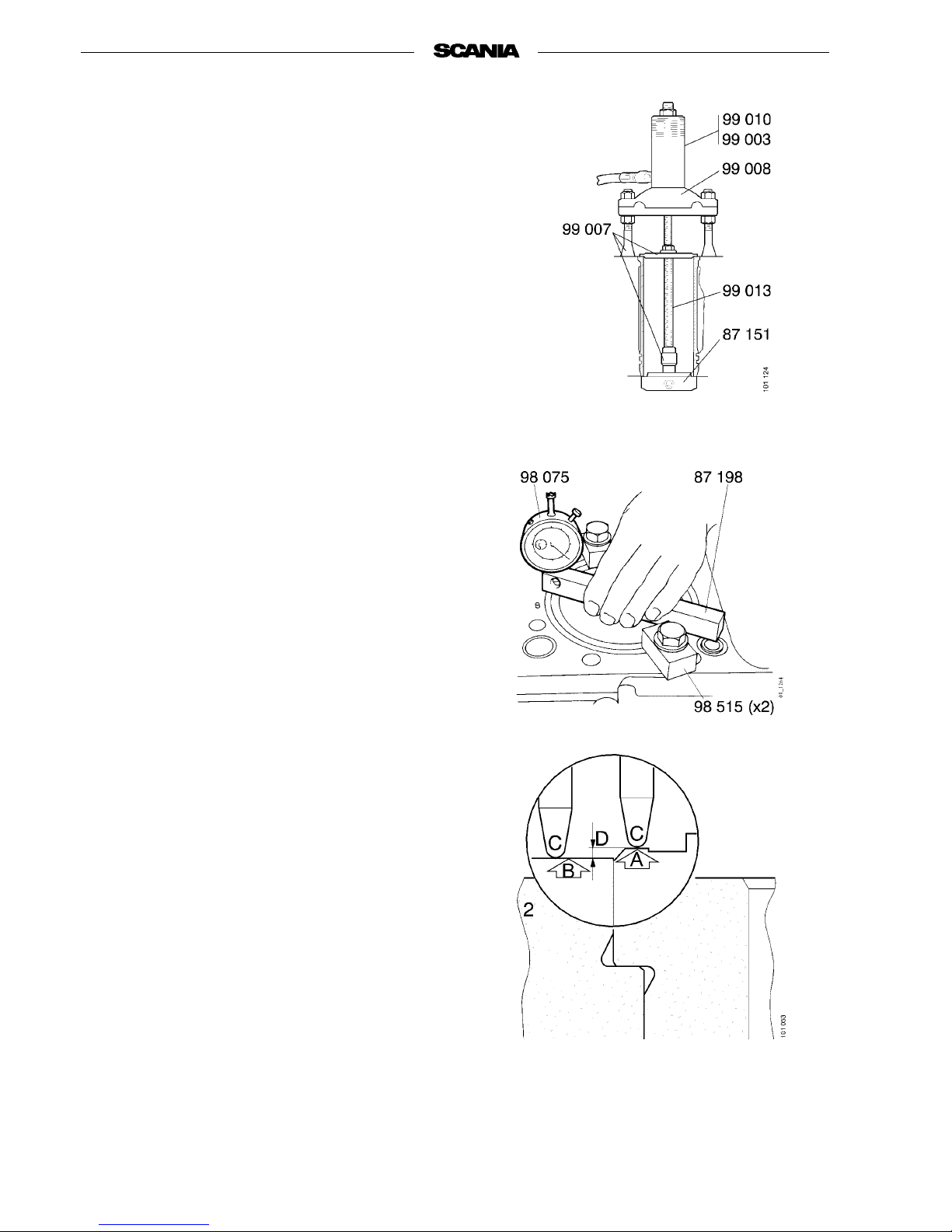
2. Extract the cylinder liner using puller
99 066 and support plate 99 007 with or without hydraulic tool.
3. Remove seals from cylinder block.
Measuring cylinder liner height
- Insert the liner without seals and press it down
using two tension lugs 98 515. Tighten bolts to
50 Nm.
- The cylinder liner and mating surfaces in the
block must be carefully cleaned before taking
measurements. Use a wire brush and carefully
scrape of carbon deposits.
- Place straight edge 87 198 with dial gauge
98 075 on the liner and reset the dial gauge
against the liner (A).
- Slide the tip of the dial gauge across to the
block (B) and measure the height of the liner
(A-B) as shown in the figure.
- Measure each liner at two diametrically opposite points.
Puller for cylinder liner with
hydraulic hole cylinder
A Measuring surface on cylinder liner
B Measuring surface on cylinder
block
C Measuring tip
D Cylinder liner height D = A-B
Page 31

01:01-02
©
Scania CV AB 1997 31
Program 96
- The cylinder liner should be slightly above the
surface of the cylinder block.
- The difference between the two measurements
on the same liner may be up to a maximum of
0.035 mm.
- Cylinder liner height D (=A-B) above the
block should be 0.27-0.33 mm.
Adjusting cylinder liner height
- Check and, if necessary, adjust the entire cylinder bank at the same time.
- The liner mating surface in the block must be
clean and in perfect condition. Affix tape
(adhesive side out) over the oilway holes in the
crankshaft. Place a cloth in the cylinder block
to collect swarf.
- If the surface is damaged it must be machined
using tool 587 272.
- Afterthe liner’s mating surface in the block has
been machined, a shim must be fitted to provide correct liner height.
- Try to aim for the least possible amount of
machining so that the thinnest possible shim
can be used. Shims are available in the following thicknesses: 0.20, 0.25, 0.30, 0.40, 0.50and
0.75 mm.
- Remove any burrs and measure the thickness
of the shims using a micrometer. Only use one
shim, i.e. a thick shim, instead of several thin
ones.
- Try to set liner height close to the upper limit
of 0.33 mm.
01:01-02
Page 32
32
©
Scania CV AB 1997 01:01-02
Program 96
Machining cylinder liner to desired height
1. Calculate the difference between the thick-
ness of the shim and how much you wish to
raise the cylinder liner. This difference is the
thickness of the layer whichmust be removed
with the cutter.
Example for calculating necessary cutting
depth:
Desired height 0.33mm
Measured cylinder liner 0.25mm
Raising cylinder liner,
0.33 - 0.25 = 0.08mm
Closest thickness of
shim 0.20mm
Layer to be removed,
0.20-0.08 = 0.12mm
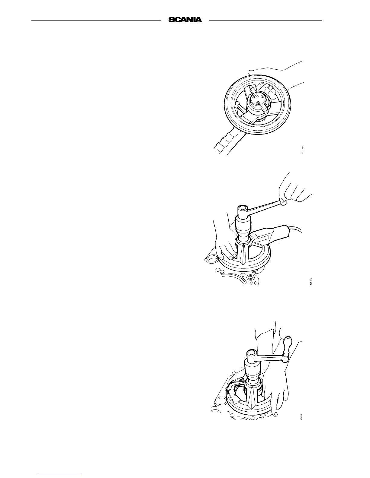
2. Clean contact surfaces between tool and
blocksurface.Fitcutterincuttingheadby
lifting the speed feed ring.
3. Centre the tool with the centre roller.
Connect the magnet (position 1).
Page 33
01:01-02
©
Scania CV AB 1997 33
Program 96
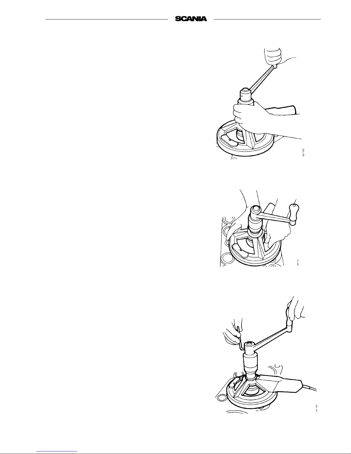
4. Raise the speed feed ring and move the cutter
forward so that the carbide tip is above the
liner seat level without touching the outer
edge.
5. Crank and, at the same time, turn the vertical
feed screw clockwise until the cutter just
comes into contact with the liner seat surface.
6. Lift the speed feed ring and withdraw the bit
until the point is just inside the liner seat surface.
7. Set the vertical feed screw to required depth.
See point 1.
Page 34
34
©
Scania CV AB 1997 01:01-02
Program 96
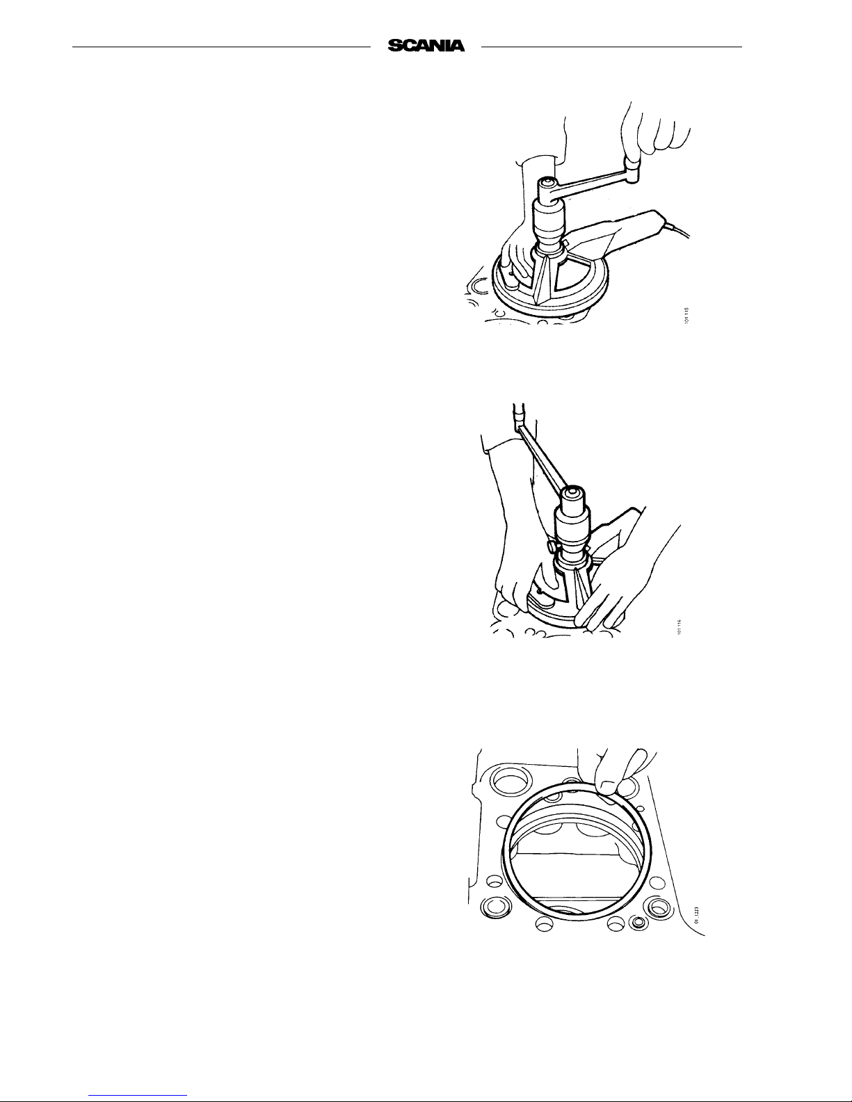
8. Crank clockwise with an even movement,
holding the horizontal feed screw with your
other hand at the same time. The bit is then
fed horizontally 0.13 mm per revolution.
9. Crank more carefully as the bit approaches
the outer edge of the cylinder liner and allow
the horizontal feed ring to slide round in your
fingers.
10. Release the ring fully as soon as the bit has
reached the outer edge so that feed ceases.
Do not move the vertical feed screw during
the machining process.
11. Move the bitback tothe centre sothat neither
bit nor engine block is damaged when the
tool is placed over the next liner seat.
Lift away the tool and place it over the next
liner seat.
12. Measure the thickness of the shim with the
tool’s micrometer.
13. Fit shim and cylinder liner.
14. Press down the cylinder liner with tension
lugs and check cylinder liner height as per
instructions.
Page 35
01:01-02
©
Scania CV AB 1997 35
Program 96
Fitting cylinder liner
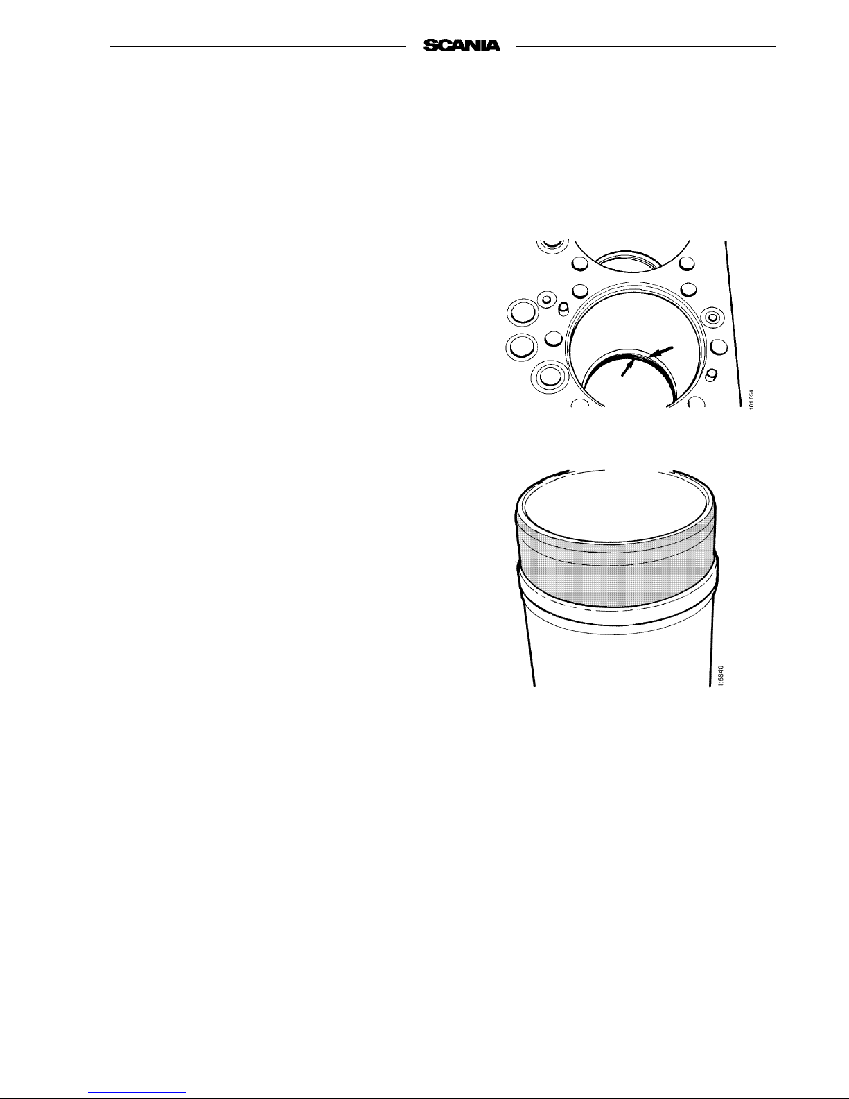
1. Check that the inside of the cylinder block is
clean.
2. Carefully check the cylinder liners, both new
and old, for cracks which may have arisen
during transport or as a result of careless handling.
3. Gently tap the liner with a metal object. It
should make a clean metallic ringing sound if
it is intact.
If it sounds cracked it should be changed.
4. Lubricate with glycerine the two seals which
are to be placed in thecylinder block andthen
fit them in the cylinder block.
5. Fit the wide seal on thecylinder liner with the
text “out” facing outwards.
Note This seal is not oil resistance and
therefore must not be lubricated.
6. Lubricate the lower guide surface on the cyl-
inder liner with glycerine.
7. Turn the liner with the punched-in cylinder
numbering to the same position it was in
before removal and carefully tap it down
using a rubber mallet. Check that the O-rings
are intact.
8. Check and adjust cylinder liner height as
described in Measuring cylinder liner height
and Adjusting cylinder liner height
Lubricate the lower part of the
cylinder liner before fitting it in
place.
Page 36
36
©
Scania CV AB 1997 01:01-02
Program 96
Fitting piston and connecting rod
1. Check that the inside of the cylinder block is
clean.
2. Remove the cover from the big-end bearing
journal and lubricate the journal.
3. Turn the piston rings so that the ringgaps are
evenly distributed round the piston.
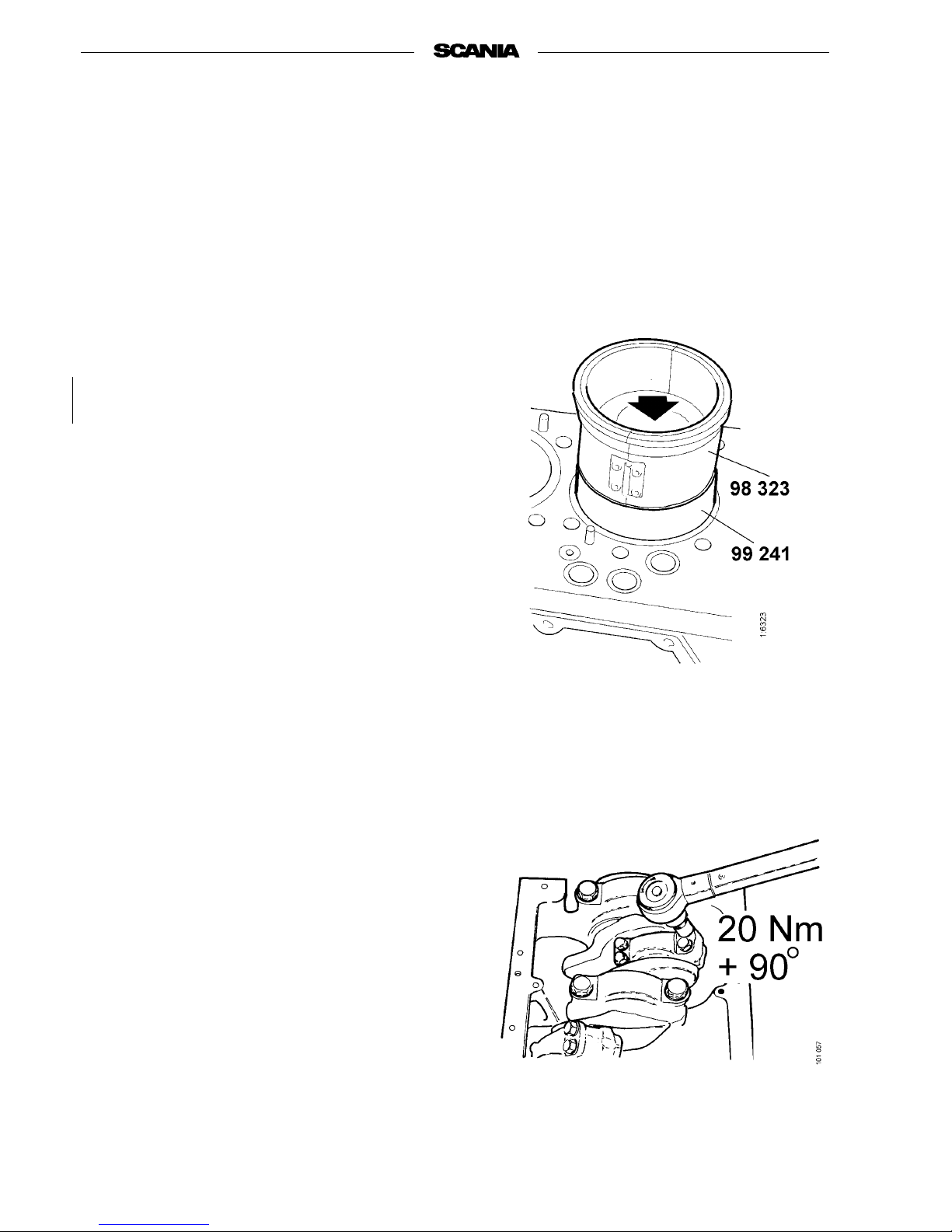
4. Fit assembly tool 99 241 instead of the loose
ring in the liner.
5. Carefully insert the connecting rod with pis-
tonsothatthearrowmarkonthepiston
points forward.
6. Lubricate piston ring compressor 98 323 and
fit it round the piston.
7. Press the piston down into the cylinder past
the assembly tool.
8. Remove the assembly tool and press in the
loose ring. Take care to press thering straight
down so that it does not enter at an angle or
become skewed.
9. Place the big-end bearing halves in the caps
and lubricate the bearing surfaces. Fit the
caps. Check thatconnecting rod and cap have
the same marking and that they are opposite
each other.
10. Lubricate the bolts, fit them and tighten alter-
nately in two stages. Stage 1: 50 Nm,
stage 2: 110 Nm.
Page 37
01:01-02
©
Scania CV AB 1997 37
Program 96
11. Check that the piston cooling nozzles are in
good condition and fully open. Blow clean
with compressed air, if necessary.
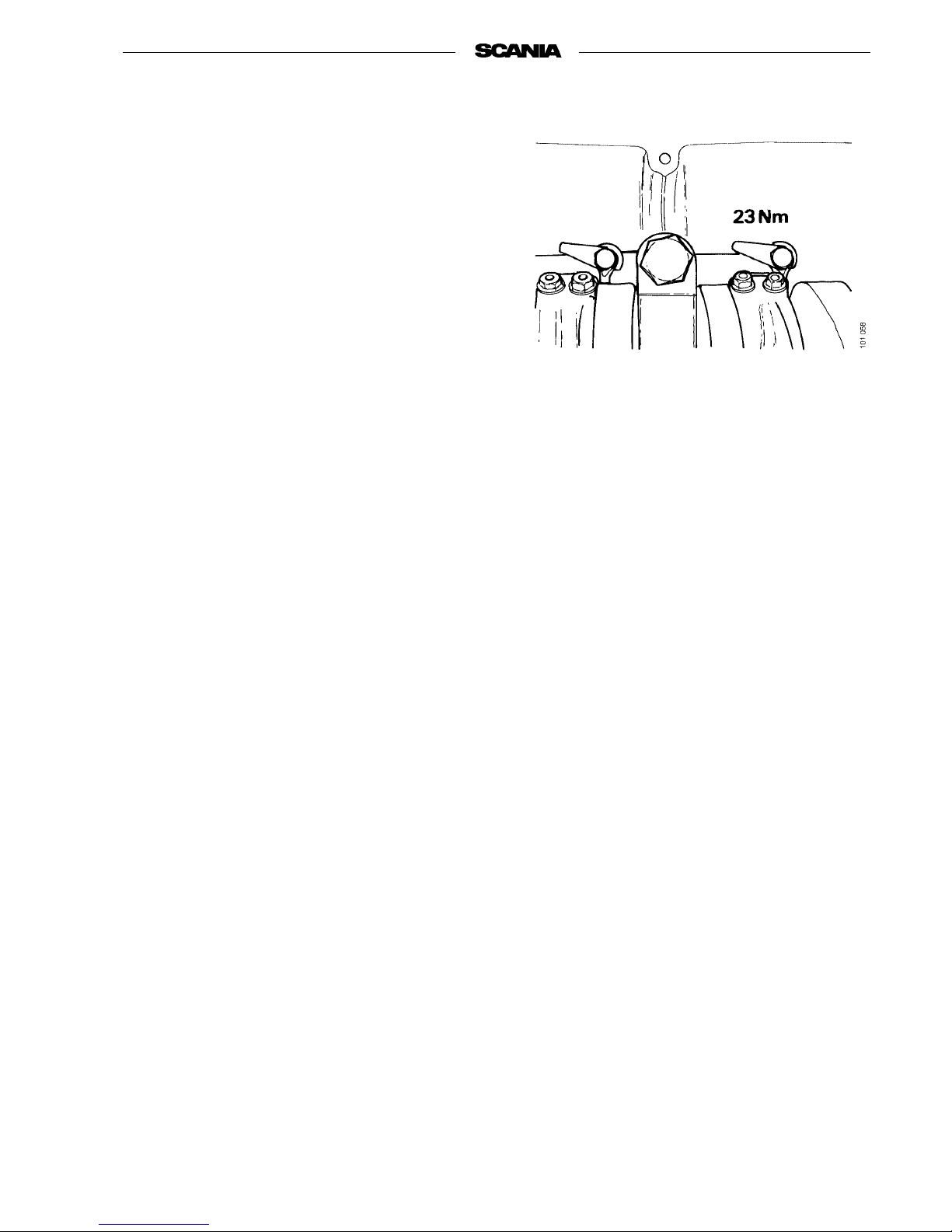
12. Fit the piston cooling nozzle and tighten the
banjo bolt to 23 Nm.
Note The piston cooling nozzle must not
be damaged.
If the jet of oil does not strike the
piston inthe right place, there could
be a danger of engine breakdown.
Damaged nozzles must be changed.
13. Fit the oil sump.
14. Fit the cylinder head.
Tighten the cylinder head bolts as described
in the Cylinder head section.
Page 38
38
©
Scania CV AB 1997 01:01-02
Program 96
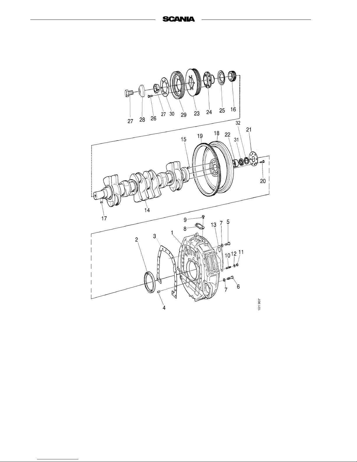
Flywheel and flywheel housing
1. Flywheel housing
2. Shaft seal
3. Gasket
4. Pin
5. Hexagon bolt
6. Hexagon bolt
7. Washer
8. Cover
9. Tapping screw
10. Stud
11. Locknut
12. Washer
13. Lifting eye
14. Crankshaft
15. Pin
16. Crankshaft gear
17. Key
18. Flywheel
19. Ring gear
20. Hexagon bolt
21. Washer
22. Guide sleeve (not standard)
23. Oscillation damper
24. Hub
25. Oil deflector
26. Bolt
27. Taper ring
28. Washer
29. Pulley (not standard)
30. Washer
31. Ball bearing (not standard)
32. Retaining ring (not
standard)
Page 39
01:01-02
©
Scania CV AB 1997 39
Program 96
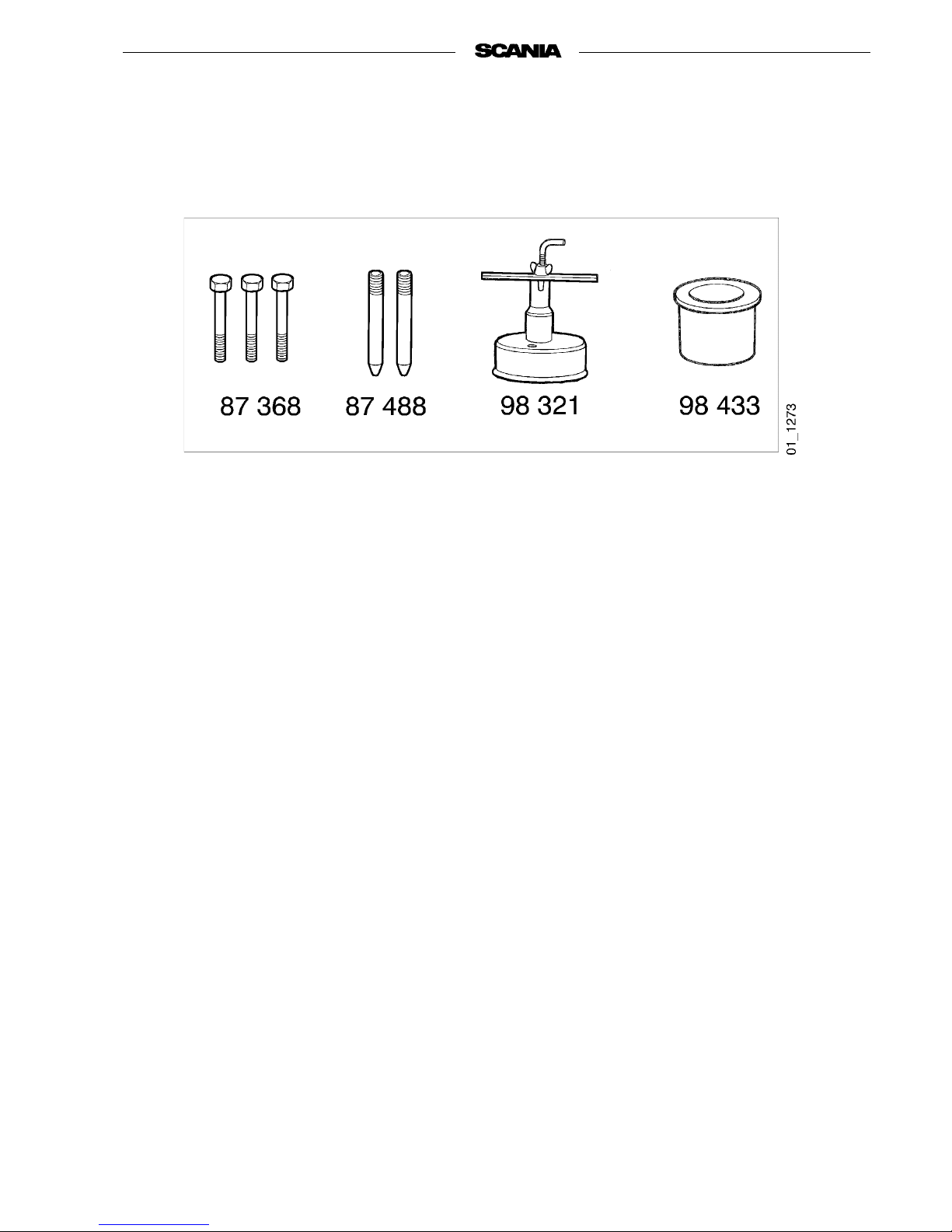
Special tools
87 368 Puller bolts
87 488 Guide pins
98 321 Assembly tool
98 433 Drift
Page 40
40
©
Scania CV AB 1997 01:01-02
Program 96
Removing flywheel
1. Remove the bolts and washer.
2. Pull the flywheel off the crankshaft using
puller bolts 87 368.
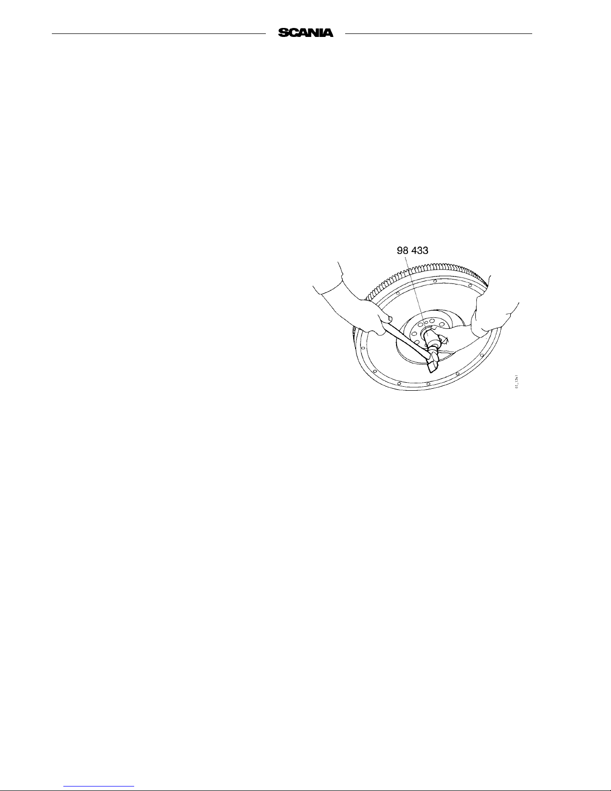
Changing the support bearing,
if fitted
1. Tap the support bearing out of the flywheel
using a drift.
2. Fit a new support bearing using drift 98 433.
Changing the ring gear
- Change the flywheel ring gear if the teeth have
become so worn that the starter motor drive
does not engage.
1. Grind as deep a grooveas possible in the ring
gear and split it using a cold chisel. Remove
the ring gear from the flywheel.
2. Clean contact surfaces on the flywheel using
awirebrush.
3. Heat the new ring gear so that it is at an even
temperature of about 100-150 °C.
Page 41
01:01-02
©
Scania CV AB 1997 41
Program 96
4. Place the heated ring gear on the flywheel so
that the chamfer on the teeth faces the starter
motor. Make sure that the ring gear abuts
firmly against the flywheel.
5. If necessary, tap the ring gear in place using a
plastic mallet.
6. The ring gear must not be cooled rapidly but
must cool down in the open air.
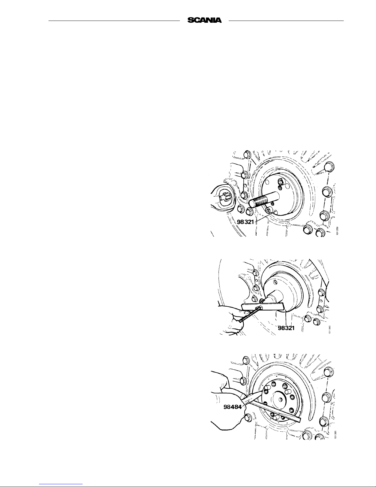
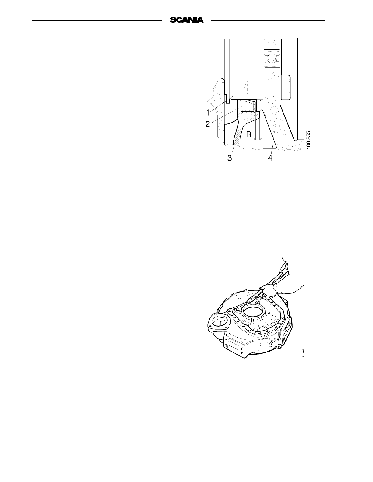
Changing crankshaft seal
1. Bolt the inner part of assembly tool 98 321 to
the crankshaft flange.
2. Fit the outerpart of assembly tool 98 321 and
screw it in until it abuts against the seal.Then
screw in the set screw against the inner part
and lock the wing nut.
3. Remove the tool and prise out the seal using
tool 98 484 and a screwdriver.
Page 42
42
©
Scania CV AB 1997 01:01-02
Program 96
Note The crankshaft seal should be fitted
dry and must not be lubricated. The
sleeve inside the seal must not be
removed until immediately before
the seal is fitted in place.
The crankshaft must be degreased
before assembly of the new seal.
4. Fit a new crankshaft seal.
5. Fit the inner part of 98 321 again. Screw in
the outer part of 98 321 until the set screw
abuts against the inner part.
Removing and fitting flywheel
housing
Changing gasket behind flywheel housing
1. Remove the starter motor.
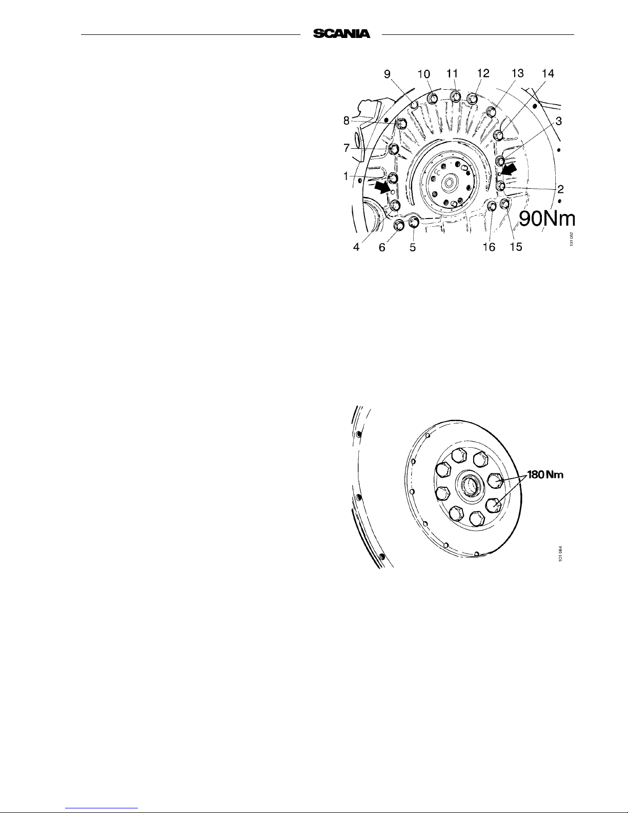
2. Remove the 16 bolts securing the flywheel
housing. Remove flywheel housing.
3. Clean the sealing surface on the flywheel
housing and engine.
Page 43
01:01-02
©
Scania CV AB 1997 43
Program 96
4. Fit a new gasket and mount the flywheel
housing on the guide pins. Tighten the bolts
to 90 Nm in the order shown in the illustration.
5. Fit a new crankshaft seal.
(See Changing crankshaft seal).
Note The seal must always be changed
when the flywheelhousing hasbeen
removed.
6. Fit the starter motor.
Fitting flywheel
1. Fit two guide pins 87 488 in the end of the
crankshaft.
2. Fit the flywheel on the crankshaft.
Note Always use new bolts.
3. Fit the washer and tighten the bolts to
180 Nm.
Page 44
44
©
Scania CV AB 1997 01:01-02
Program 96
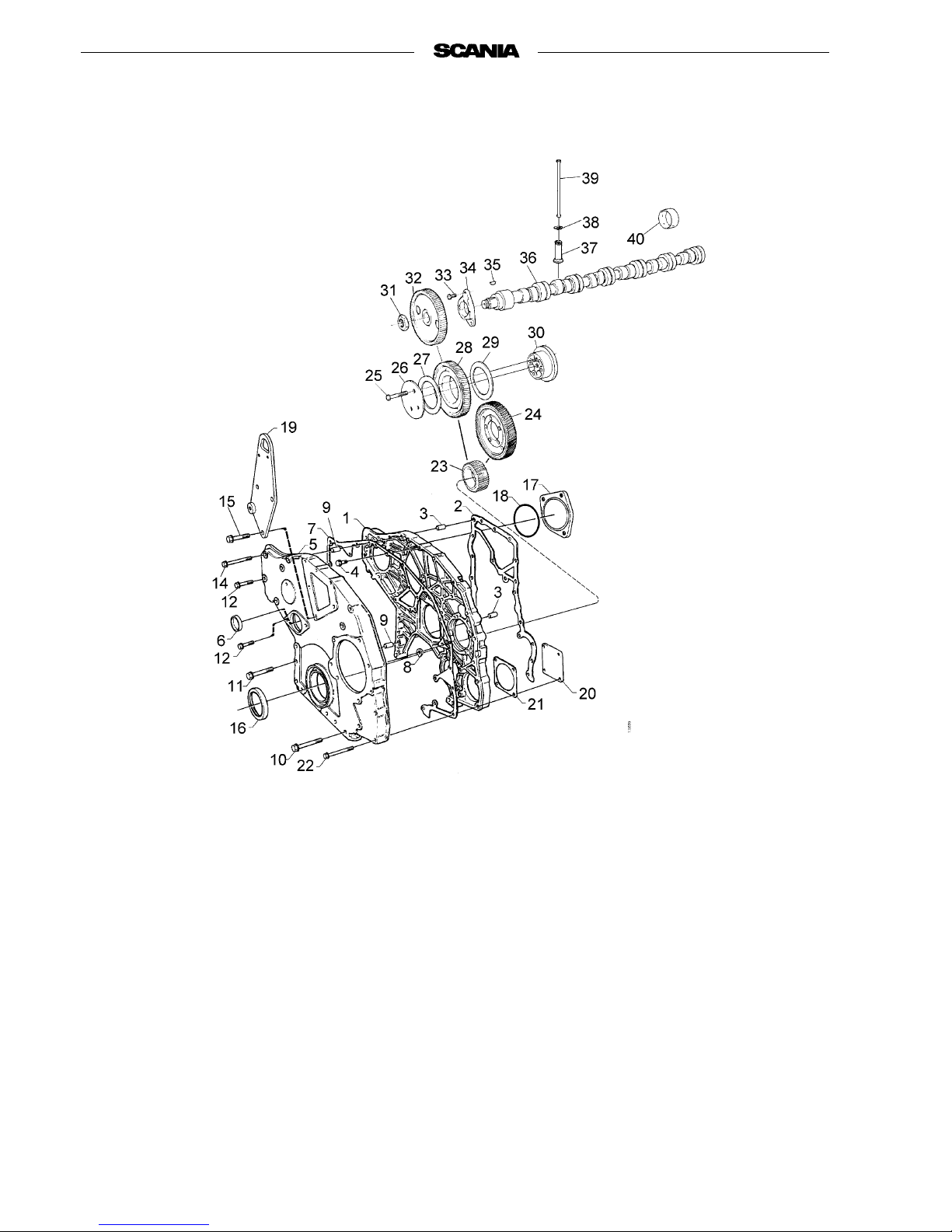
Timing gear
1. Timing gear housing
2. Gasket
3. Pin
4. Flange bolt
5. Timing gear cover
6. Core plug
7. Gasket
8. Gasket
9. Pin
10. Flange bolt
11. Flange bolt
12. Flange bolt
13. Flange bolt
14. Flange bolt
15. Flange bolt
16. Crankshaft seal
17. Cover
18. O-ring
19. Lifting eye
20. Cover
21. Gasket
22. Flange bolt
23. Crankshaft gear
24. Injection pump gear
25. Bolt
26. Washer
27. Thrust bearing
28. Intermediate gear
29. Thrust bearing
30. Shaft journal
31. Nut
32. Camshaft gear
33. Flange bolt
34. Guide flange
35. Key
36. Camshaft
37. Tappet
38. Retaining ring
39. Pushrod
40. Bushing
Page 45
01:01-02
©
Scania CV AB 1997 45
Program 96
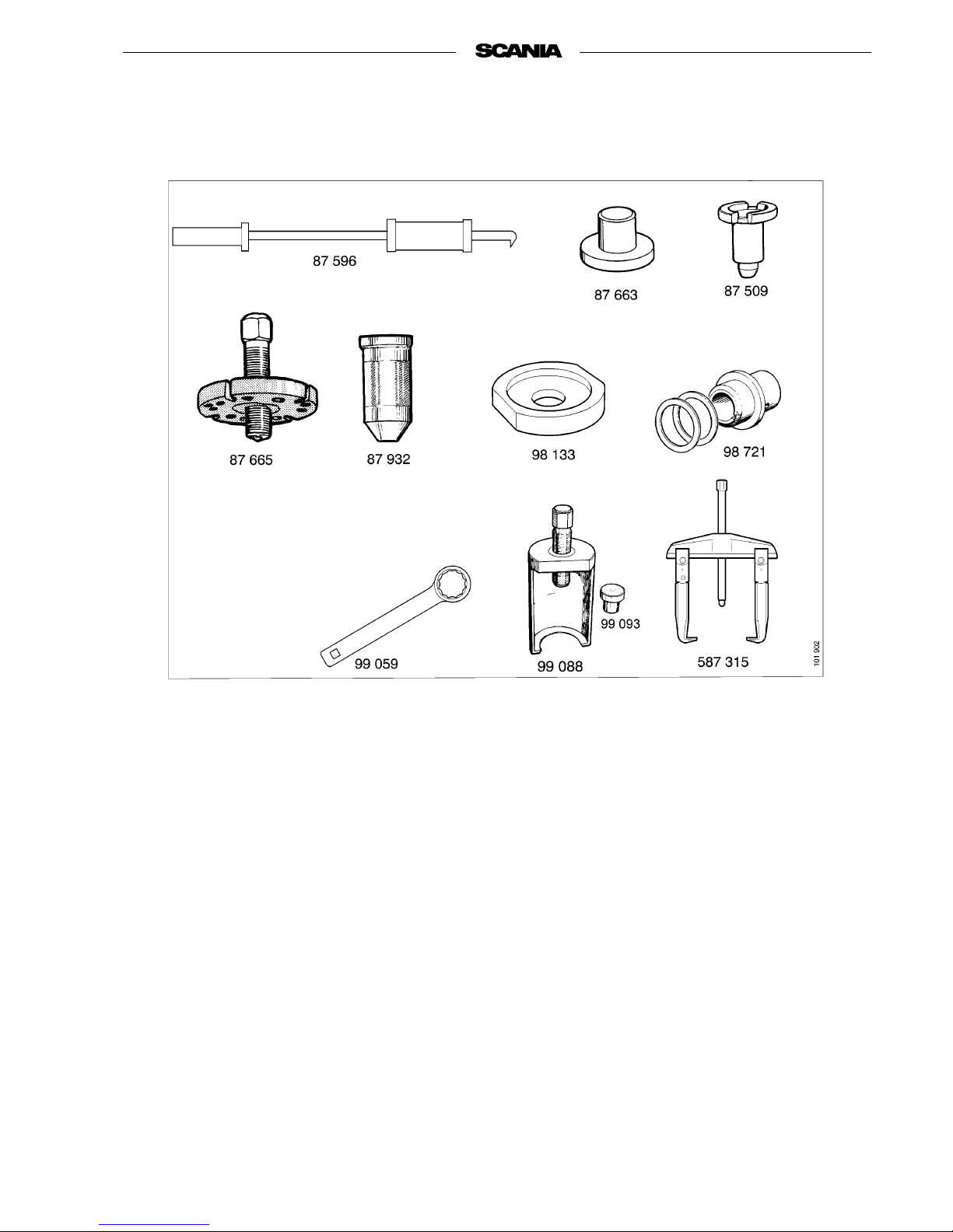
Special tools
87 509 Drift
87 596 Slide hammer
87 663 Support drift
87 665 Puller
87 932 Drift
98 133 Washer
98 721 Assembly tool
99 059 Slogging wrench
99 088 Puller
99 093 Support drift
587 315 Puller
Page 46
46
©
Scania CV AB 1997 01:01-02
Program 96
Crankshaft seal
Removing
1. Remove components that are in the way:
radiator, fan ring, fan or belt guard.
2. Undo the crankshaft damper bolts and those
for the belt pulley, if fitted. Remove the
crankshaft damper and belt pulley, if fitted.
Take care to avoiddamaging thecrankshaft
damper.
3. Remove the crankshaft bolt in front of the
damper hub.
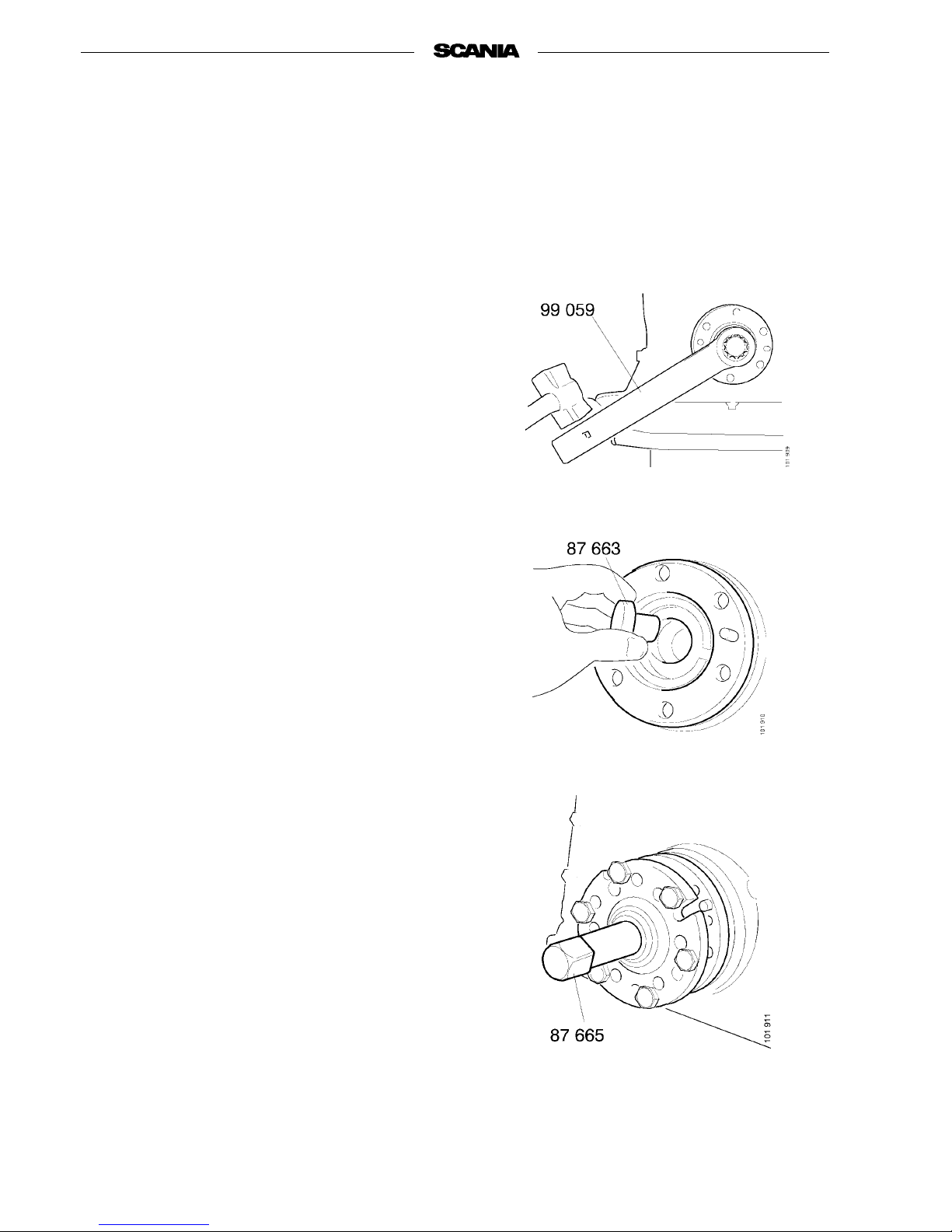
Use slogging wrench 99 059.
4. Fit support drift 87 663 in the end of the
crankshaft.
5. Screw onpuller 87 665 with all sixbolts. Pull
the hub out 2-5 mm.
Then unscrew the bolt a few turns and tap the
hub in to loosen the cone.
6. Pull the hub off altogether.
7. Remove the seal using slide hammer 87 596.
Protect the end of the crankshaft against
scratches.
01:01-02
Page 47
01:01-02
©
Scania CV AB 1997 47
Program 96
Fitting
1. Wipe clean the seal seat in the housing.
Note The crankshaft seal should be fitted
dry and must not be lubricated. The
sleeve inside the seal must not be
removed until immediately before
the seal is fitted in the engine.
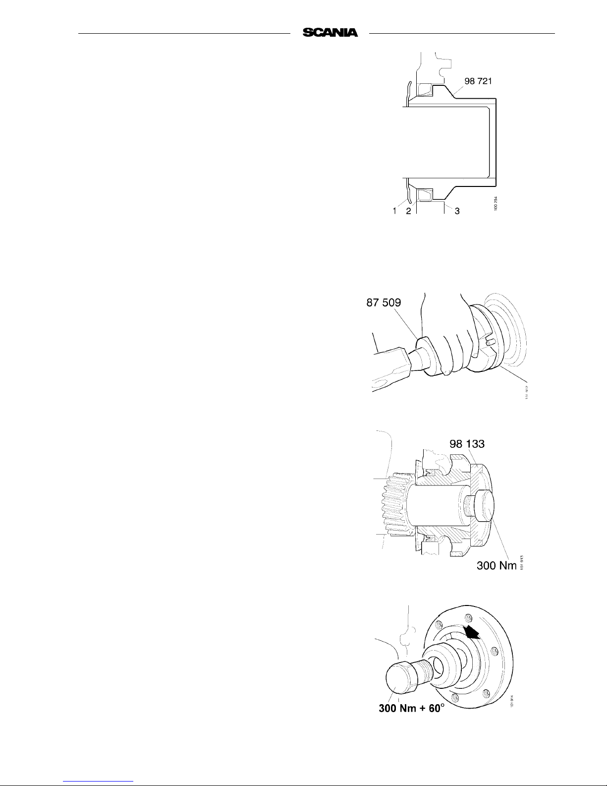
2. Use assembly tool 98 721 to press in the seal.
This tool is tapped in using a copper hammer.
3. Degrease the surface of the oscillation
damper hub in contact with theseal and drive
on the hub using drift 87 509.
4. Fit the crankshaft bolt with washer 98 133
but without the cone in the hub. Tighten the
crankshaft bolt to 300 Nm.
5. Remove the crankshaft bolt and washer
98 133 and fit the cone. Screw in the crankshaft bolt with attendant washer. Tighten first
to 300 Nm and then a further sixth of a turn
(60°) using slogging wrench 99 059.
6. Fit the oscillation damper and, if fitted, the
belt pulley.
Tighten the bolts to 110 Nm.
7. Refit the components that were removed ear-
lier because they were in the way.
1. Oil deflector
2. Seal
3. Timing gear cover
Page 48
48
©
Scania CV AB 1997 01:01-02
Program 96
Timing gear cover
Removing
1. Remove components that are in the way:
radiator, fan ring, fan, belt guard, alternator,
V-belt, belt tensioner, tensioning rollers, fan
drive, alternator bracket.
2. Turn the engine over to the ignition position.
3. Undo the crankshaft damper bolts and those
for the belt pulley, if fitted. Remove the
crankshaft damper and belt pulley, if fitted.
Take care toavoid damaging the crankshaft
damper.
4. Remove the crankshaft bolt in front of the
damper hub.
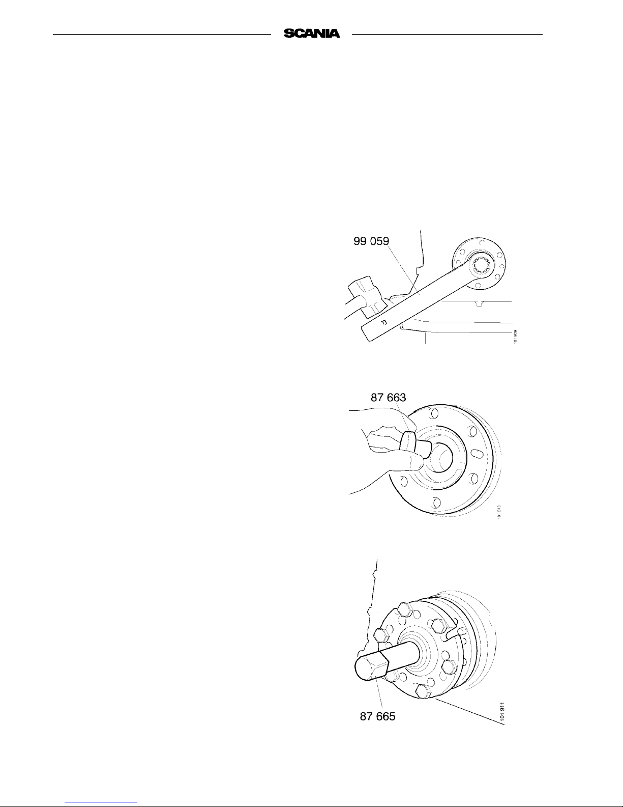
Use slogging wrench 99 059.
5. Fit support drift 87 663 in the end of the
crankshaft.
6. Screw onpuller 87 665 with allsix bolts.Pull
the hub out 2-5 mm. Then unscrew the bolt a
few turns and tap the hub in to loosen the
cone.
7. Pull the hub off altogether.
8. Remove the seal using slide hammer 87 596.
Protect the end of the crankshaft against
scratches.
9. Engine equipped with compressor:
Remove the coolant manifold between the
coolant pump and compressor.
10. Undo the three compressor retaining bolts in
the timing gear housing. Extract the compressor and gear.
Page 49
01:01-02
©
Scania CV AB 1997 49
Program 96
11. Check that the engine is in the ignition posi-
tion.
12. Remove the oil sump.
13. Remove the timing gear housing.
Fitting
1. Clean the mating surfaces and fit a new gasket.
2. Fit the timing gear housing in place and
tighten the bolts to a torque of 39 Nm.
3. Fit a new crankshaft seal.
See Crankshaft seal: Fitting.
4. Drive on the oscillation damper hub using
drift 87 509.
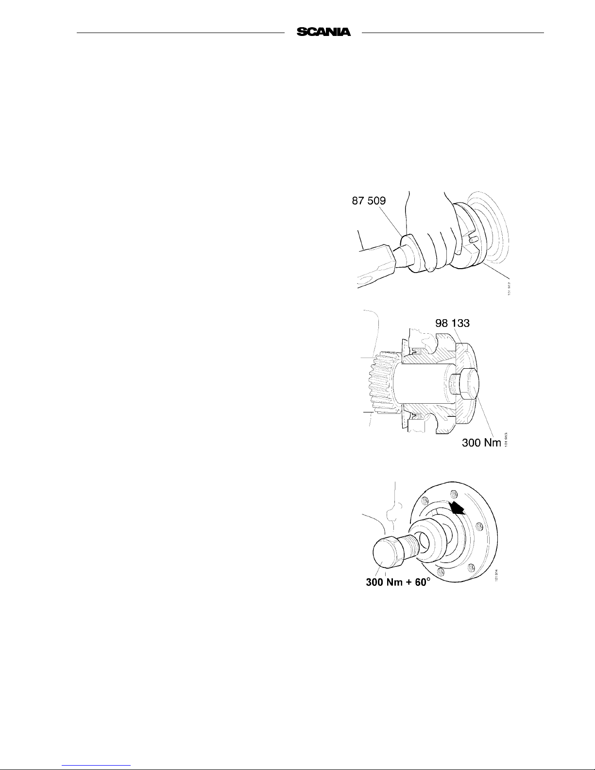
5. Fit the crankshaft bolt with washer 98 133
but without the cone in the hub. Tighten the
crankshaft bolt to 300 Nm.
6. Remove the crankshaft bolt and washer
98 133 and fit the cone. Screw in the crankshaft bolt with attendant washer. Tighten first
to 300 Nm and then a further sixth of a turn
(60°) using slogging wrench 99 059.
7. Fit the oil sump with a new gasket.
8. Refit the components that were removed ear-
lier because they were in the way.
Page 50
50
©
Scania CV AB 1997 01:01-02
Program 96
Intermediate gear
Removing
1. Remove the timing gear cover.
See Timing gear cover: Removing.
2. Remove oil catcher from end of crankshaft.
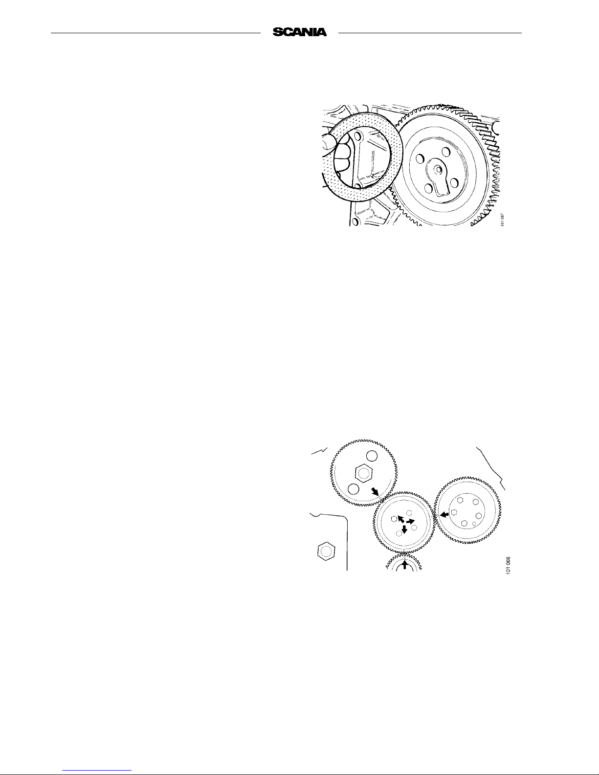
3. Turn the crankshaft so that the marks on the
camshaft gear and crankshaft gear point
towards the centre of the intermediate gear.
4. Remove the intermediate gear.
Note After the intermediate gear has been
removed, the camshaft and crankshaft must not be moved. Pistons
andvalvescouldthenstrikeeach
other and sustain damage.
Fitting
1. Lubricate the bearing surfaces and fit the
intermediate gear and thrust bearings so that
all marks are in the correct positions.
2. Fit the washer and tighten the bolts to a
torque of 39 Nm.
3. Fit the oil catcher on the end of the crankshaft.
4. Fit the timing gear cover.
See Timing gear cover: Fitting.
Page 51
01:01-02
©
Scania CV AB 1997 51
Program 96
Crankshaft gear
Removing
1. Remove the timing gear cover.
See Timing gear cover: Removing.
2. Remove oil catcher from the end of the
crankshaft. Remove oil pump.
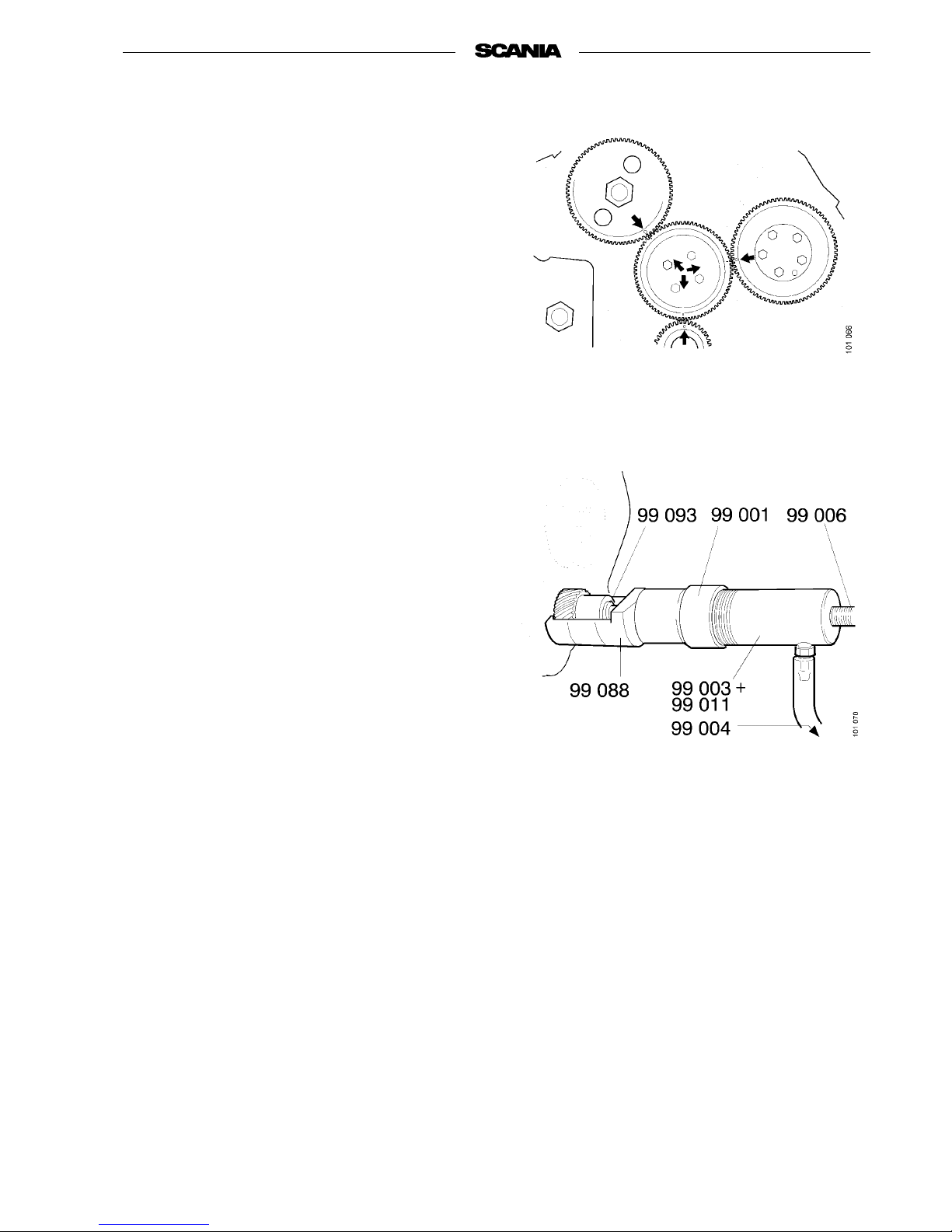
3. Turn the crankshaft so that the marks on the
camshaft gear and crankshaft gear point
towards the centre of the intermediate gear.
4. Remove the intermediate gear. If necessary,
also remove the oil pump gear.
5. Pull off the crankshaft gear using puller
99 088 and support drift 99 093, with or without the aid of the hydraulic tool as shown in
the figure.
Note After the intermediate gearhas been
removed, the camshaft and crankshaft must not be moved. Pistons
andvalvescouldthenstrikeeach
other and sustain damage.
Fitting
1. Lubricate the end of the crankshaft using
engine oil.
2. Heat the gear to 130 °C and fit it onto the
shaft with the marking facing outwards.
Make sure that the key is fitted in place. Use
drift 87 932 and tap the gear fully home.
3. Fit the intermediate gear.
See Intermediate gear: Fitting, points 1-2.
4. Fit the oil pump.
5. Fit oil catcher on end of crankshaft.
6. Fit the timing gear cover.
See Timing gear cover: Fitting.
Page 52
52
©
Scania CV AB 1997 01:01-02
Program 96
Camshaft gear
Removing
1. Remove the timing gear cover.
See Timing gear cover: Removing.
2. Remove oil catcher from end of crankshaft.
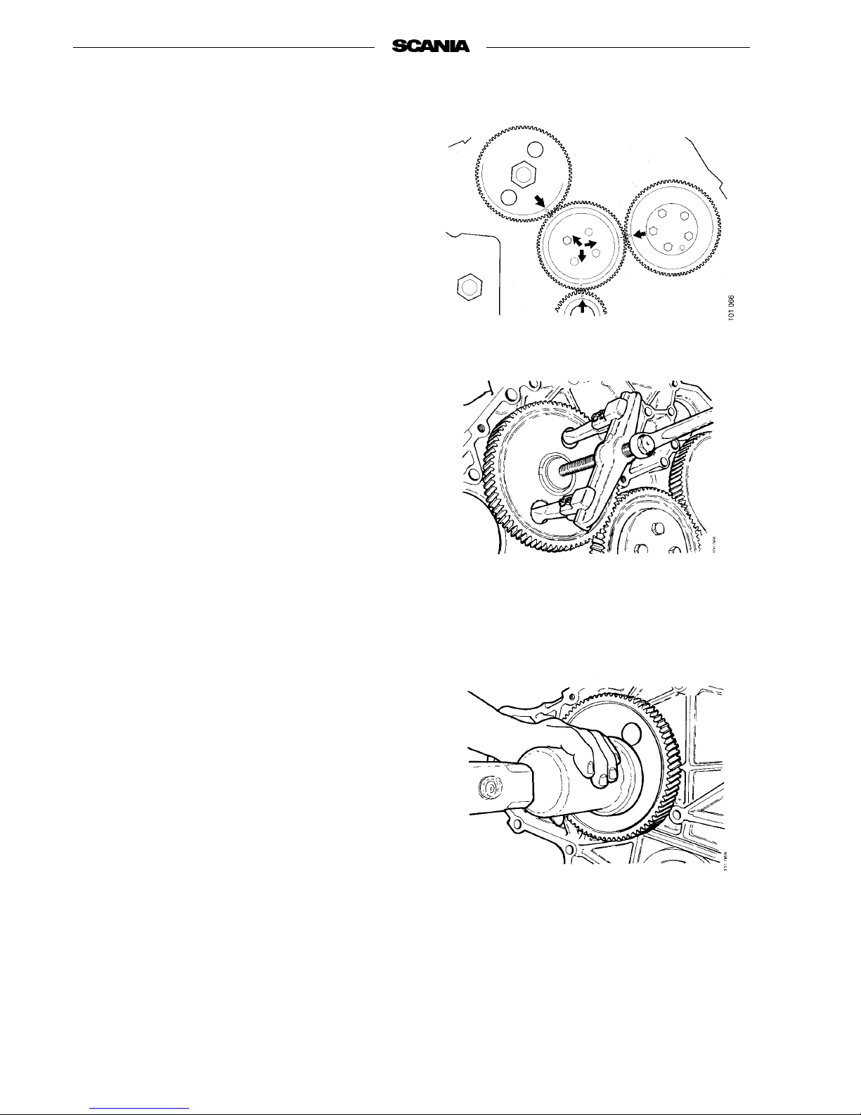
3. Turn the crankshaft so that the marks on the
camshaft gear and crankshaft gear point
towards the centre of the intermediate gear.
4. Remove the intermediate gear.
5. Pull off the camshaft gear using puller
587 315.
Note After theintermediate gear hasbeen
removed, the camshaft and crankshaft must not be moved. Pistons
andvalvescouldthenstrikeeach
other and sustain damage.
Fitting
1. Lubricate the end of the camshaft using
engine oil.
2. Heat the gear to 100 °C and drive it onto the
shaft with the marking facing outwards.
Make sure that the key is fitted in place.
3. Fit the intermediate gear.
See Intermediate gear: Fitting, points 1-2.
4. Check that the gear has cooled down. Secure
the flywheel. Tighten the camshaft nut to a
torque of 600 Nm.
5. Fit oil catcher on end of crankshaft.
6. Fit the timing gear cover.
See Timing gear cover: Fitting.
Page 53

01:01-02
©
Scania CV AB 1997 53
Program 96
Camshaft
Removing
- It is assumed that the timing gear housing has
already been removed.
1. Remove rocker arms and pushrods.
2. Turn crankshaft around until the tooth marked
”O” on the crankshaft gear and camshaft gear
point towards the centre of the intermediate
gear. In this position, the camshaft guide
flange bolts can be accessed through the holes
in the camshaft gear.
3. Remove the side covers with valve tappets.
4. Undo the camshaft gear retaining nut. The
camshaft gear can now be pulled off the camshaft using puller 587 315 or can be left in
place when the camshaft is extracted.
5. Remove the intermediate gear and the guide
flange bolts.
6. Extract the camshaft from the front. Take care
to avoid damaging cams and bearings.
Fitting
1. Lubricate and pushin thecamshaft. Becareful
not to damage cams and bearings.
2. Fit the guide flange bolts.
3. Fit the intermediate gear,
see Intermediate gear: Fitting, points 1-2.
4. Fit the camshaft gear,
see Camshaft gear: Fitting, points 1-4.
5. Lubricate the camshaft cams. Fit the side cov-
ers with a new gasket.
6. Lubricate pushrods and rocker arms with
motor oil and fit them in place.
Page 54

54
©
Scania CV AB 1997 01:01-02
Program 96
Changing valve tappets
1. Clamp the side cover in a vice. Remove the
retaining ring and valve tappet.
2. Fit a new valve tappet. Fit the retaining ring,
using a screwdriver.
Camshaft bearings
- There is very little wear on the camshaft and
camshaft bearings and thesecomponents rarely
need any work to be done on them.
- However, when reconditioning the engine,
check that the bearing surfaces and cams are
not abnormally worn.
- Fit new bearings so that the lubricating holes
are opposite the oilways in the block.
Checking camshaft setting
1. Set the crankshaft at TDC for No. 1 cylin-
der’s compression stroke (valves closed).
2. Set up two dial gauges against the valve
spring thrust washers.
3. Adjust the rocker arms so that there is no
clearance and then an additional 0.1 mm (see
that both valves are open 0.1 mm).
4. Zeroize both dial gauges.
5. Turn the crankshaft one revolution in its
direction of rotation until the TDC position is
reached again.
6. Read the two dial gauges and compare the
results with the values given below:
Intake valve lifting height 0.55-1.65 mm
Exhaust valve lifting height 0.50-1.50 mm
Page 55
01:01-02
©
Scania CV AB 1997 55
Program 96
Crankshaft
Removing
1. Remove the cylidner heads and pushrods.
2. Remove the flywheel and flywheel housing.
3. Remove the fan, fan bearing, oil sump, tim-
ing gear housing and intermediate gear.
4. Remove the oil pump and all pistons and con-
necting rods.
5. Remove all main bearing caps and carefully
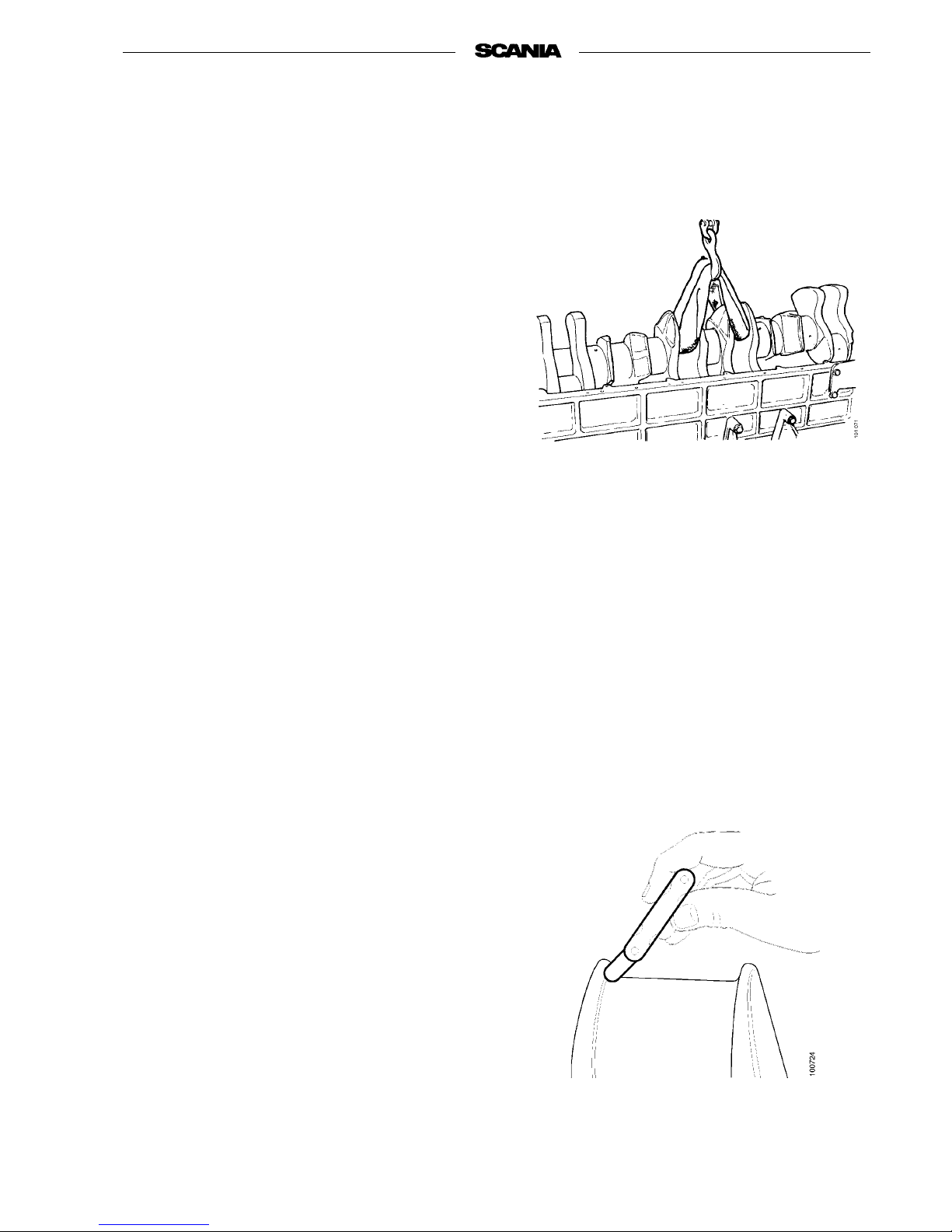
lift out the crankshaft using a lifting strap or
the like which will not damage the shaft journals.
6. Remove all main bearing halves and thrust
washers on the 7th main bearing.
Checking and grinding
1. Measure the crankshaft pivot pins. Use a
micrometer to take measurements at two
points 90 degrees apart.
If either of these diameters is below the specified lower limit, regrinding of the crankshaft
or the fitting of a replacement crankshaft
should be considered.
The oil pressure should also be taken into
account, which is in turn also affected by
wear in the main and big-end bearings.
2. When regrinding, stated undersizes must be
complied with. There are bearings adapted to
these dimensions.
It is important that the fillet radius of the
pivot pins is correct.
After grinding the pivot pins, the oil hole orifices at the bearing surfaces should be
rounded and polished.
Page 56
56
©
Scania CV AB 1997 01:01-02
Program 96
Fitting
1. Be particularly careful to clean all oilways in
the crankshaft, pivot pins and contact surfaces for bearings and caps.
2. Check that the dimensions of bearings and
thrust washers are correct. Fit the bearing
halves in block and cap. Generously lubricate
bearings and pivot pins.
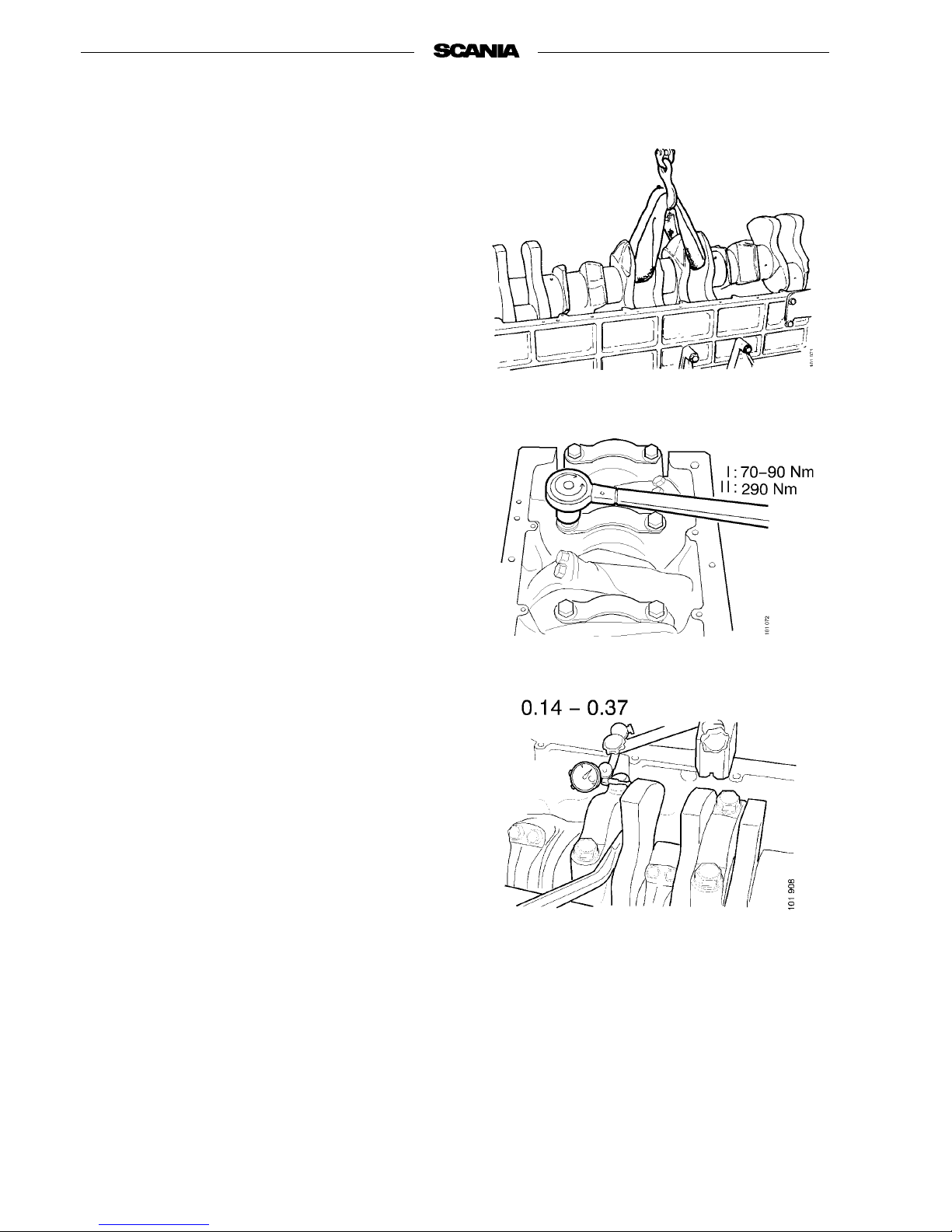
3. Carefully lift in the crankshaft. Fit the thrust
washers and place the caps as marked.
4. Lubricate the bolt threads and start by tight-
ening the cap bolts to 90 Nm. The tighten the
bolts to 290 Nm.
Check that the crankshaft rotates easily.
5. Check crankshaft axial clearance. It should be
0.14-0.37 mm. The clearance can be adjusted
by changing the thrust bearing washers.
6. Fit pistons, connecting rods and oil pump.
7. Fit the fan bearing and fan, oil sump, timing
gear housing and intermediate gear.
8. Fit the flywheel and flywheel housing.
9. Fit the cylinder heads and pushrods.
Page 57
01:01-02
©
Scania CV AB 1997 57
Program 96
Lubrication system
Oil cooler
Changing seals an d oil cooler
element
1. Remove the drive belt.
2. Drain the cooling system.
3. Remove pipes and hoses connected to the
coolant pump and oil cooler.
4. Detach the oil cooler and coolant pump from
the engine.
5. Unscrew the coolant pump retaining bolts
and remove pump and pump housing.
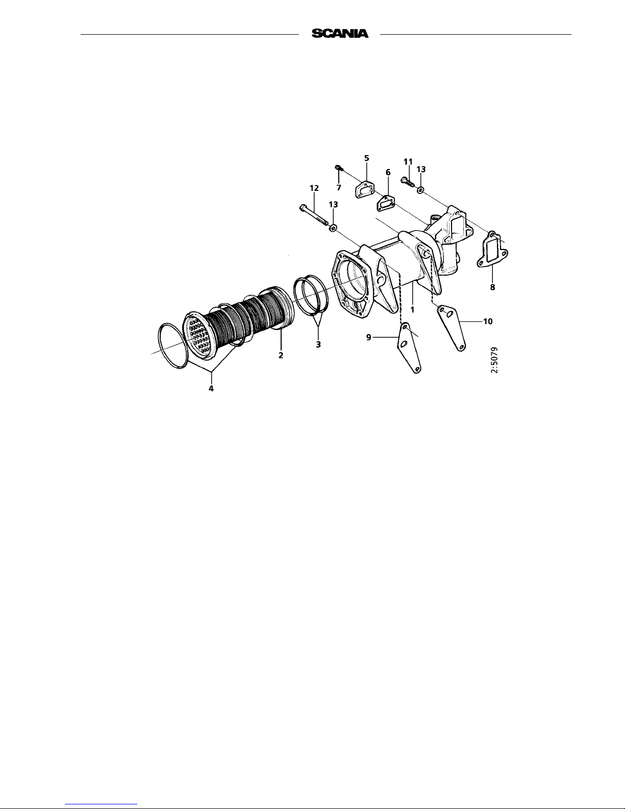
1. Housing
2. Cooling element
3. Seal
4. Connection
housing
5. Bolt
6. Plug
7. Cover
8. Gasket
9. Flange bolt
10. Gasket
11. Gasket
12. Gasket
13. Flange bolt
14. Flange bolt
15. Flange
Page 58
58
©
Scania CV AB 1997 01:01-02
Program 96
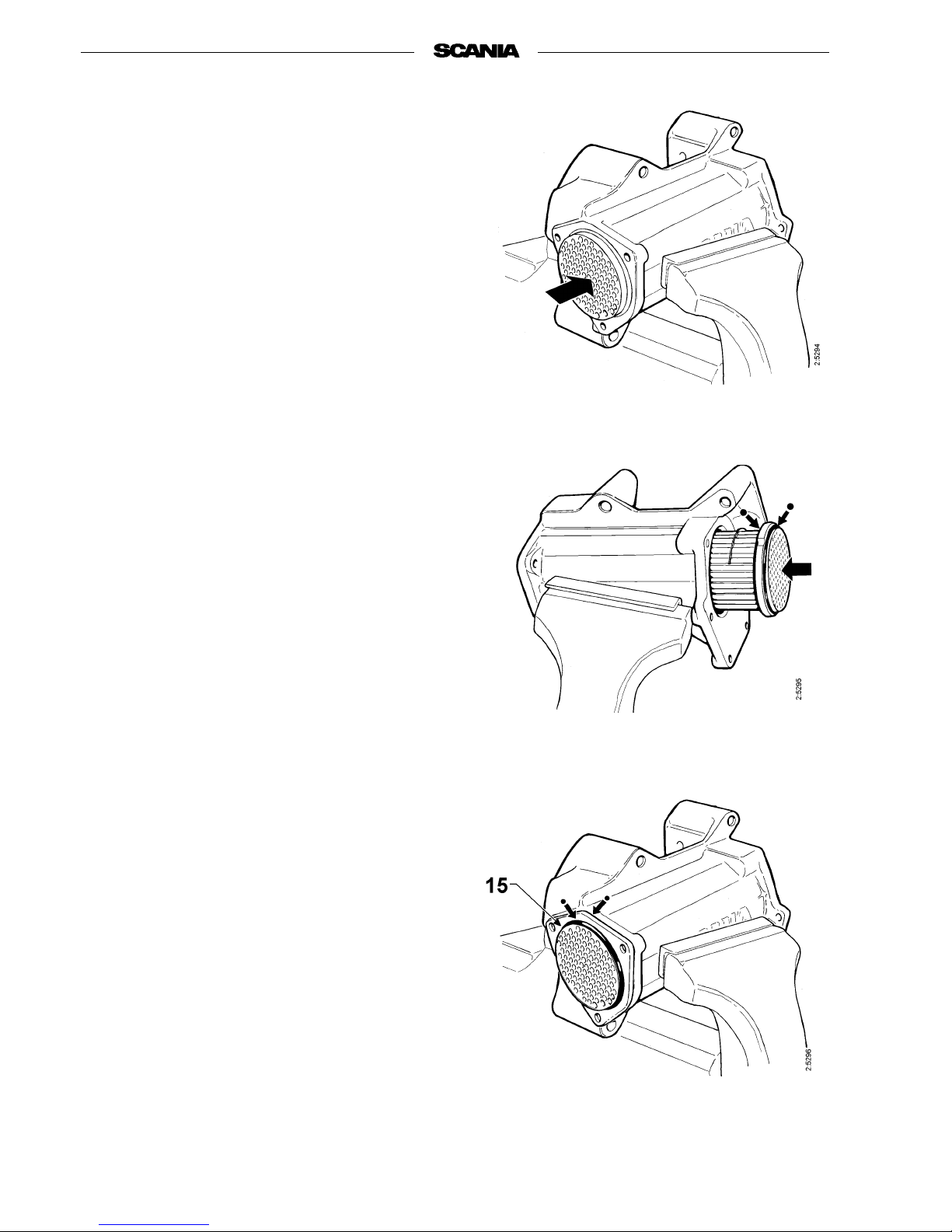
6. Clamp the oil cooler in a vice fitted with soft
jaws. Do not clamp the jaws on the oil
cooler’s sealing surfaces. Remove cover 7
on connection housing 4 and unscrew the
connection housing.
7. Remove the O-ring and loose flange 15 and
press out element 2.
8. Fit new greased O-rings on both sides of the
element’s flange and insert the element into
the housing from the pump side.
9. Fit a new greased O-ring on the opposite side
of the element and press it into the oil cooler
housing.
10. Fit t he loose flange and turn it to the right
position.
11. Fit another greased O-ring outside the loose
flange. Press on the connection housing and
screw it in place to a tightening torque of
20 Nm. Fit the cover on the connection housing.
12. Turn the element to the right position and
screw on the pump housing and coolant
pump with a new gasket in between. Tighten
the flange bolts to 42 Nm.
13. Attach the oil cooler unit to the engine. Use
new gaskets.
Tighten the flange bolts to 42 Nm.
14. Connect the pipes and hoses that were previ-
ously detached.
15. Fit the drive belt.
16. Fill the cooling system with c oolant.
See Oils, lubricants, liquids, section 0for the
composition of the coolant.
Inserting the element into the housing with
new O-rings
Pressing out the cooling element
Fitting new O-rings and the loose flange
Page 59
01:01-02
©
Scania CV AB 1997 59
Program 96
Oil cleaner
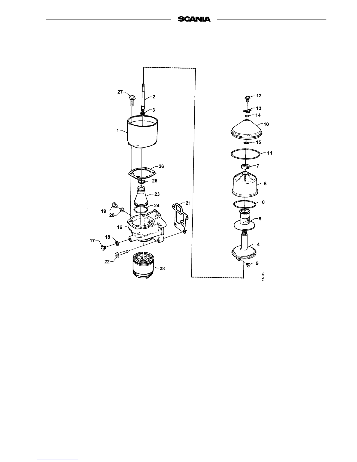
1. Rotor housing
2. Shaft
3. Washer
4. Rotor
5. Strainer
6. Rotor bowl
7. Nut
8. O-ring
9. Nozzle
10. Cover
11. O-ring
12. Locking screw
13. Washer
14. O-ring
15. Retaining ring
16. Cyclone housing
17. Plug
18. Gasket
19. Plug
20. Gasket
21. Gasket
22. Flange bolt
23. Cyclone
24. O-ring
25. O-ring
26. Gasket
27. Flange bolt
28. Oil filter
The
ex
plo
de
dview
dr
aw
ing
to g
o
in
her
e
Page 60
60
©
Scania CV AB 1997 01:01-02
Program 96
Dismantling and assembly
- During routine cleaning of the oil cleaner, it
should be found that a certain amount of dirt
has been deposited in the rotor bowl.
- If this is not the case, it indicates that the rotor
is not turning. The cause of this must be investigated immediately.
- If it is found at the recommended cleaning
intervals that the dirt deposits exceed 20 mm,
the rotor bowl should be cleaned more often.
1. Unscrew the locknut securing the outer cover
and remove the cover.
2. Lift out the rotor. Wipe the outside clean.
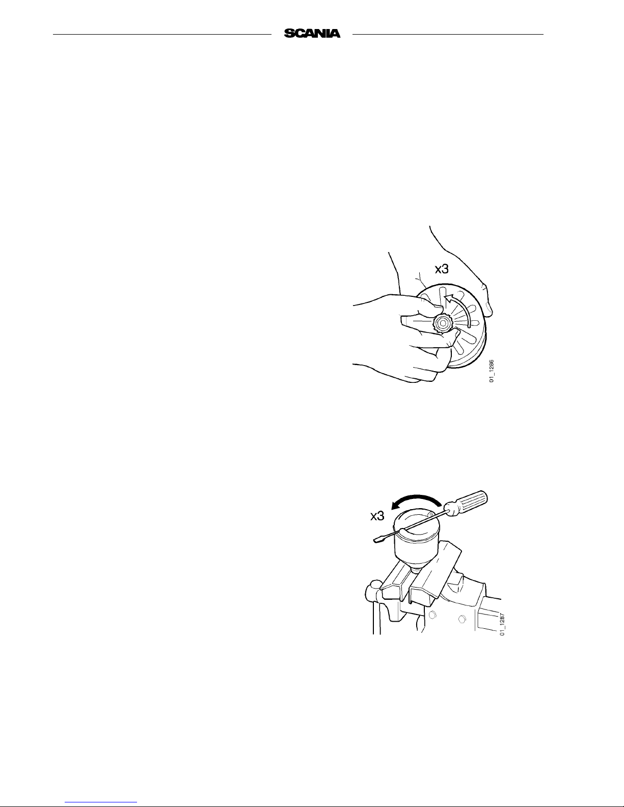
Slacken the rotor nut and unscrew it about
three turns to protect the bearing.
Note Never clamp the rotor in a vice.
Never strike the rotor bowl.
This could give rise to consequential damage which might cause
imbalance.
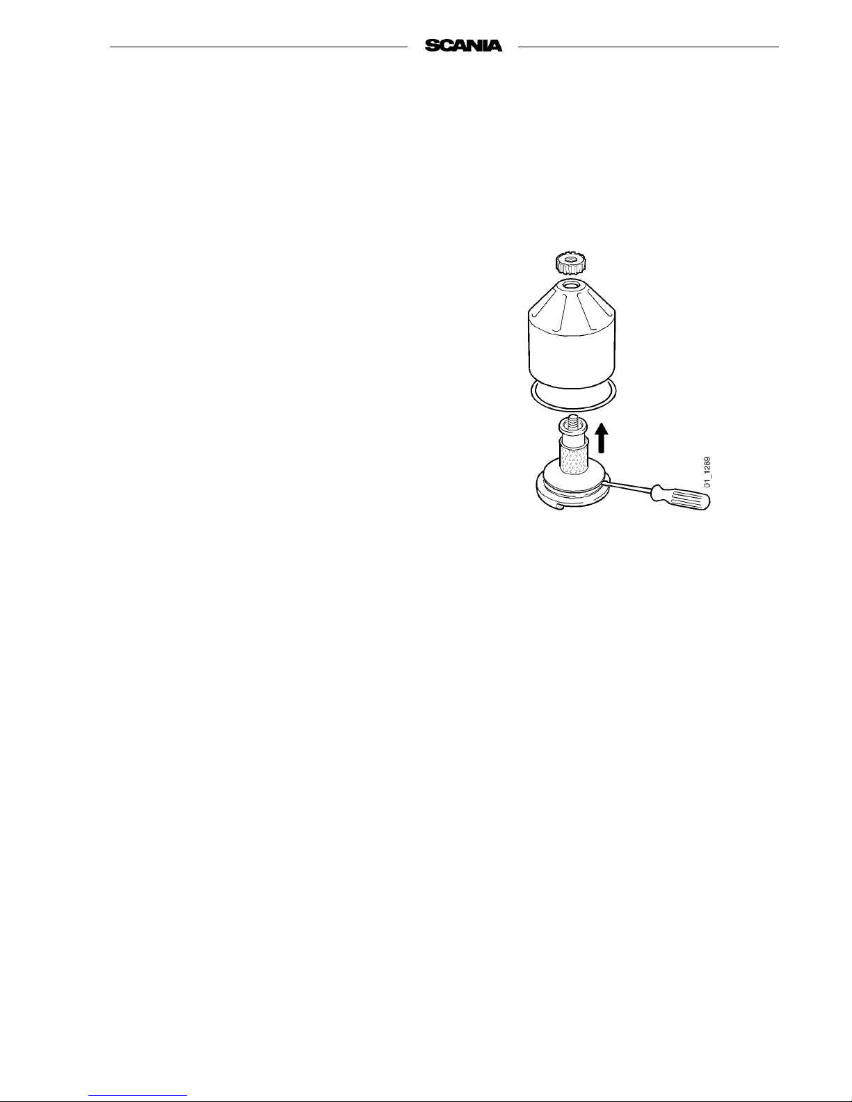
3. If it is difficult to loosen the rotor nut, turn
the rotor upside down and clamp the rotor nut
in a vice.
4. Turn the rotor anticlockwise three turns by
hand or, if this does not succeed, by placing a
screwdriver between the outlet holes.
Page 61
01:01-02
©
Scania CV AB 1997 61
Program 96
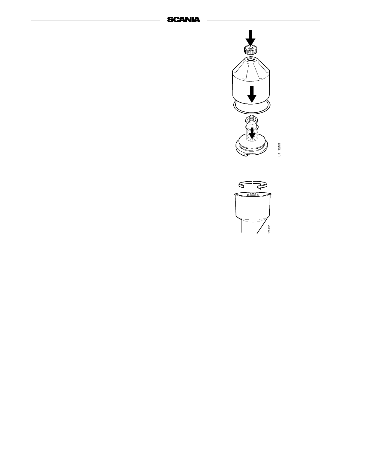
5. Hold the rotor bowl and tap the rotor nut
lightly with your hand or with aplastic mallet
until the rotor bowl comes away from the
rotor.
Note Never hit the rotor directly as this
could damage its bearings.
6. Remove the rotor nut and bowl from the
rotor.
7. Remove the rotorinsert from inside the rotor.
If the strainer is stuck, carefully prise it loose
using a knife inserted at the bottom between
rotor and strainer.
8. Scrape the deposits off the inside of the bowl
using a knife.
9. Wash the parts.
10. Check the two nozzles on the rotor.
Make sure that they are not blocked or damaged. Change damaged nozzles.
11. Check that the bearings are not damaged.
12. Place the O-ring in position in the bowl.
Change the O-ring if it is even slightly damaged.
Page 62
62
©
Scania CV AB 1997 01:01-02
Program 96
13. Assemble the parts and tighten the rotor nut
hard by hand.
14. Check that the shaft is not loose. If it is, it
should be locked using locking compound
561 200. First clean it thoroughly with a suitable solvent.
15. Tighten the rotor shaft using socket wrench
98 421. Tightening torque 34 Nm.
16. Refit the rotor and spin it by hand to make
sure that it turns easily.
17. Check the O-ring on the cleaner housing
cover and fit the cover, securing it with the
locknut.
Tighten the locknut to 10 Nm.
Page 63
01:01-02
©
Scania CV AB 1997 63
Program 96
Oil pump
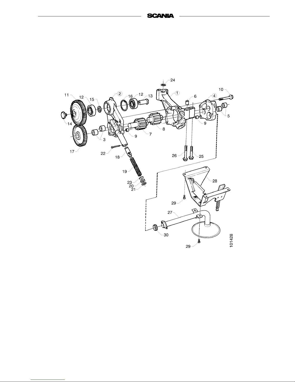
In the case of leakage or a fault in the oil pump, it should not be reconditioned but should be changed as a
complete unit.
1. Oil pump housing
2. Oil pump cover
3. Bushing
4. Oil pump cover
5. Bushing
6. Guide sleeve
7. Pump wheel
8. Pump wheel
9. Guide sleeve
10. Flange bolt
11. Oil pump gearwheel
12. Ball bearing
13. Shaft
14. Bolt
15. Spacing ring
16. Retaining ring
17. Oil pump gearwheel
18. Piston
19. Spring
20. Plug
21. O-ring
22. Split pin
23. Shim
24. O-ring
25. Flange bolt
26. Flange bolt
27. Suction pipe
28. Bracket
29. Flange bolt
30. Seal
Page 64
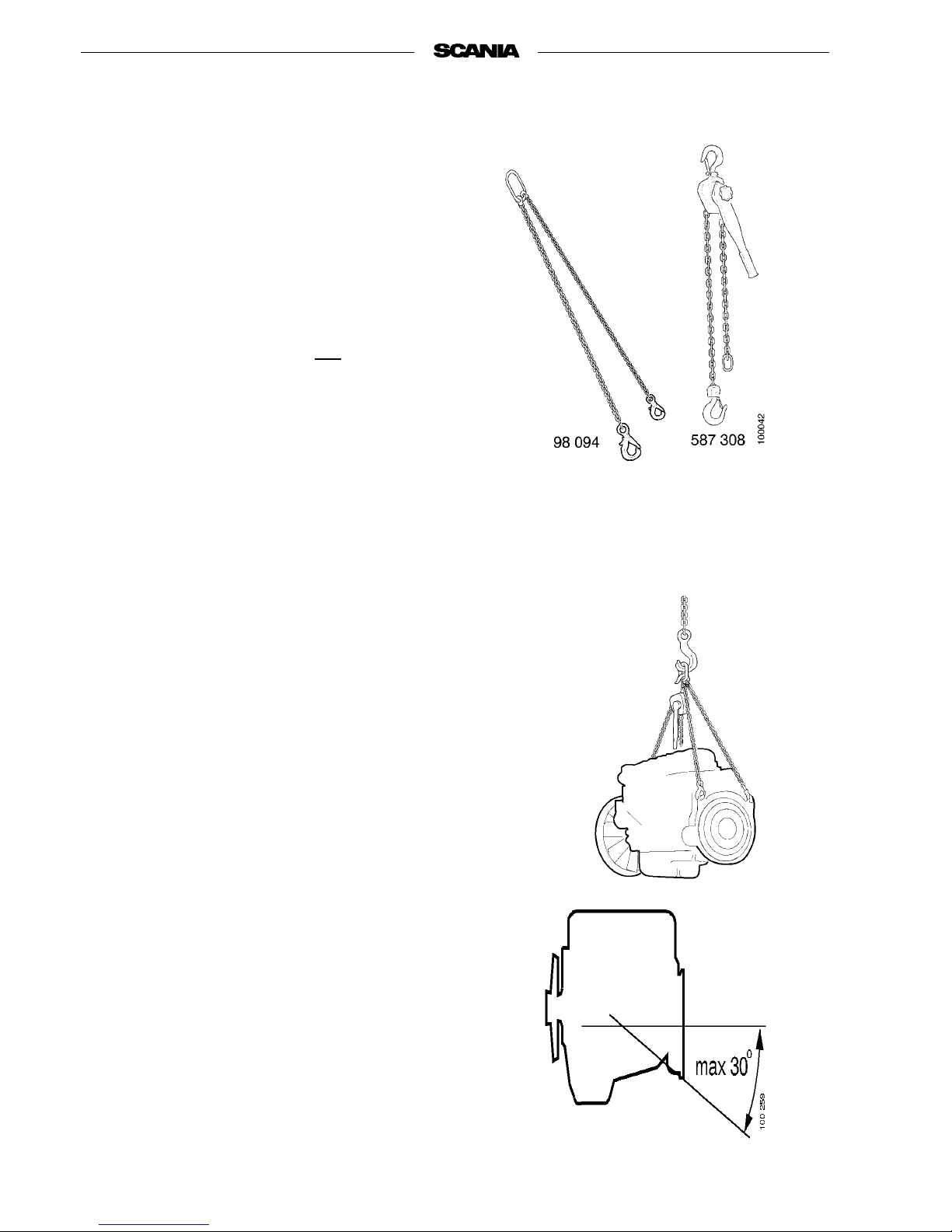
64
©
Scania CV AB 1997 01:01-02
Program 96
Lifting the engine
Special tools
Note The engine lifting eyes are sized for
lifting the engineonly, not the engine
together with connected equipment
(alternator, gearbox, etc.) or frame.
- Fasten lifting chain 98 094 in the rear lifting
eyes.
- Fasten lever block 587 308 in the front lifting
eyes.
Important The lifting eyes are sized for a maxi-
mum lifting angle of 30°.
98 094 Lifting chain
587 308 Lever block
Page 65

01:01-02
©
Scania CV AB 1997 65
Program 96
Specifications
General information
Cylinderconfiguration.................................... In-lineengine
Numberofcylinders..................................... 6
Cylinderbore .......................................... 115mm
Stroke ................................................ 144mm
Sweptvolume .......................................... 8.97 dm3
Numberofmainbearings ................................. 7
Firingorder............................................ 1-5-3-6-2-4
Injection............................................... Direct
Operation.............................................. 4stroke
Cooling ............................................... Liquid
Approx.weight,incl.alternator............................. 805kg
Directionofrotation(engineviewedfromrear)................ anticlockwise
Locking compound, lubricants, sealing compounds
T Activator for faster curing of locking compound 561 200....... 561045
Locking compount....................................... 561200
Lubricantforexhaustpipeboltsandjoints.................... 561205
Sealantforcylinderliner.................................. 584010
Thread-lockingadhesive.................................. 561019
Cylinder head
Minimumcylinderheadheightaftermachining,page17......... 114.4 mm
Distance “B” between cylinder head surface and valve head, page 11
Withnewparts,min...................................... 0.78 mm
Withmachinedparts,max................................. 1.80 mm
Intake valve
Clearance(coldengine)................................... 0.45 mm
Headangle............................................. 19.4°-19.6°
MinimumdimensionAformachinedvalve,page10............ 3.0mm
Compression ratio
Output
Engine speed
Torque
Oil capacity
Oil grade
See Operator’s Manual.
Page 66

66
©
Scania CV AB 1997 01:01-02
Program 96
Exhaust valve
Clearance(coldengine) ...................................0.80 mm
Headangle..............................................44.4°-44.6°
MinimumdimensionAformachinedvalve,page10.............1.7mm
Intake valve seat
Seatangle ..............................................20.0°
ContactsurfacewidthA,page11............................2.3-2.8mm
ValveseatringOD.......................................53.066 - 53.079 mm
Position for valve seat ring, diameter .........................53.000 - 53.019 mm
Position for valve seat ring, depth............................11.25 - 11.35 mm
Exhaust valve seat
Seatangle ..............................................45.0°
ContactsurfacewidthA,page11............................1.9-2.6mm
ValveseatringOD.......................................49.081 - 49.092 mm
Position for valve seat ring, diameter .........................49.000 - 49.016 mm
Position for valve seat ring, depth............................11.25 - 11.35 mm
Valve guides
Length,intake...........................................68.2 mm
exhaust..........................................68.2 mm
Height above surface for valve guide:
intake............................................16.7 mm
exhaust..........................................16.7 mm
Rocker arm mechanism
Rockerarmbushing,ID(pressedinandmachined)..............30.007 - 30.028 mm
Surface quality ..........................................0.8Ra
Oil hole diameter drilled to same diameter as in rocker arm.
Page 67

01:01-02
©
Scania CV AB 1997 67
Program 96
Tightening torques
Cylinder head bolts:
Firsttightening....................................... 60Nm
Secondtightening..................................... 150Nm
Thirdtightening ...................................... 250Nm+90°
Injectornut............................................. 70Nm
Nutforadjustingscrewonrockerarm....................... 40Nm
Rockercoverbolt........................................ 20Nm
Exhaustmanifoldbolts................................... 50Nm
Rockerarmmechanismbolts .............................. 150Nm
Turbocharger
Wear limits
Radialshaftclearance.................................... 0.329-0.501 mm
Axial shaft clearance (after running in)....................... 0.038-0.093 mm
Tightening torques
Bolts,turbocharger-exhaustpipe........................... 40Nm
Hoseclip,exhaust....................................... 5Nm
Pistons and cylinder liners
Cylinder liner
Shimsforcylinderliner,thickness .......................... 0.20, 0.25, 0.30,
0.40, 0.50, 0.75 mm
Cylinder liner height above cylinder block . ................... 0.27 - 0.33 mm
Maximum permitted height difference on individual liner
between measurements read at two diametrically opposite
pointsacrosstheengine.................................. 0.035 mm
Page 68

68
©
Scania CV AB 1997 01:01-02
Program 96
Pistons
Fitted with arrow on piston crown facing forwards.
Piston rings
Numberofcompressionrings...............................2
Gap: 1string .........................................0.4-0.75 mm
2ndring.........................................0.3-0.6mm
Clearance in groove max 2nd ring ...........................0.25 mm
Rings marked “TOP” should be turned with the marking facing upwards.
Numberofoilscraperrings ................................1
Gap ...............................................0.3-0.55 mm
Clearance in groove max...................................0.25 mm
Connecting rods
Connecting rods and caps marked 1 to 6.
Fitted with marking facing inwards.
Tightening torques
Boltsfortensionlugswhenpressingdowncylinderliner.........50Nm
Oilsumpbolts...........................................20Nm
Connecting rod bolts (oiled threads)..........................20Nm+90°
Flywheel and flywheel housing
Flywheel
Maximum machining of contact surface for plate: See group 4, Clutch
Ring gear
Heated to 100 - 150 °C before fitting.
Page 69

01:01-02
©
Scania CV AB 1997 69
Program 96
Flywheel housing
Seal in flywheel housing: Dimension B, page 43 ............... 7mm
Tightening torques
Flywheelbolts.......................................... 180Nm
Bolts for flywheel housing ................................ 90Nm
Timing gear
Camshaft gear
Heated to 100 °C before fitting.
Backlashagainstintermediategear.......................... 0.03 - 0.18 mm
Injection pump gear
Backlashagainstintermediategear.......................... 0.03 - 0.16 mm
Intermediate gear
Axialclearancemax ..................................... 0.23 mm
Power take-off gear
Backlashagainstintermediategear.......................... 0.03 - 0.18 mm
Camshaft
Axialclearance ......................................... 0.15 - 0.30 mm
Page 70

70
©
Scania CV AB 1997 01:01-02
Program 96
Crankshaft
Mainbearingraces...............................Diameter:
Standard 95.000 - 94.978 mm
Undersize 1 94.750 - 94.728 mm
Undersize 2 94.500 - 94.478 mm
Undersize 3 94.250 - 94.228 mm
Undersize 4 94.000 - 93.978 mm
Undersize 5 93.750 - 93.728 mm
Undersize 6 93.500 - 93.228 mm
Fillet radius 4.75 - 4.85 mm
Surface quality 0.25 Ra
Width, max 46.78 mm
Bearing clearance 0.054 - 0.116 mm
Big-endbearingjournals...........................Diameter:
Standard 80.000 - 79.981 mm
Undersize 1 79.750 - 79.731 mm
Undersize 2 79.500 - 79.481 mm
Undersize 3 79.250 - 79.231 mm
Undersize 4 79.000 - 79.981 mm
Undersize 5 78.750 - 78.731 mm
Undersize 6 78.500 - 78.481 mm
Fillet radius 4.8 - 5.2 mm
Surface quality 0.25 Ra
Width, max 53.10 mm
Bearing clearance 0.050 - 0.112 mm
Thrustbearing...................................Thickness:
Standard 3.38 - 3.43 mm
Oversize 1 3.46 - 3.51 mm
Oversize 2 3.51 - 3.56 mm
Oversize 3 3.64 - 3.69 mm
Oversize 4 3.89 - 3.94 mm
Oversize 5 4.27 - 4.32 mm
Axial clearance 0.14 - 0.37 mm
Page 71

01:01-02
©
Scania CV AB 1997 71
Program 96
Tightening torques
Tightening torques
Nutforcamshaftgear .................................... 600Nm
Nutforcompressorgear .................................. 200Nm
Boltsforintermediategearshaftjournal...................... 49Nm
Main bearing bolts:
StageI............................................. 70-90Nm
StageII............................................ 290Nm
Flywheelbolts.......................................... 180Nm
Crankshaftbolt ......................................... 300Nm+60°
Fan................................................... 30Nm
Lubrication system
Oil pump
Backlash:
Crankshaftgear-intermediategearonoilpump............... 0.03 - 0.36 mm
Intermediategear-crankshaftgear.......................... 0.03 - 0.16 mm
Oil pressure valve (Note: not safety valve)
Oil pressure:
With hot engine at 2000 rpm............................... 4-6bar
Withhotengineat800rpm................................ min.1.5bar
Freespringlength ....................................... 98mm
Oil cleaner
Permitted thickness of deposits on wall of bowl................ 20mm
Oil filter
Use only genuine Scania filters (screwed on by hand).
Page 72

72
©
Scania CV AB 1997 01:01-02
Program 96
Tightening torques
Oil pump:
Boltsforoilpumpcover...................................22Nm
Bolts,oilpump-cylinderblock.............................42Nm
Lockbolt(left-handthread)forintermediategear...............40Nm
Oil cleaner:
Locknut for oil cleaner housing cover ........................10Nm
Nutforrotorbowl........................................Tightenbyhand
Rotorshaft..............................................34Nm
Oil nozzle for piston cooling:
Banjobolt..............................................23Nm
Page 73

01:01-02
©
Scania CV AB 1997 73
Program 96
Special tools
Part number Designation Shown on page
87 125 Puller 4, 8
87 198 Straight-edge for dial gauge 25, 30
87 362 Drift 25, 29
87 368 Puller bolt 40
87 488 Guide pins 43
87 509 Drift 45, 47, 49
87 596 Slide hammer 45, 46, 48
87 663 Support drift 45, 46, 48
87 665 Puller 45, 46, 48
87 932 Drift 45, 51
87 961 Drift 4, 15
98 075 Dial gauge 25, 30
98 094 Lifting chain 64
98 133 Washer 45, 47, 49
98 323 Piston ring compressor 25, 36
98 249 Compression tester 4, 6
98 321 Assembly tool 39, 41
98 421 Socket wrench 62
98 433 Drift 39, 40
98 500 Shank 4, 11
98 503 Drift 11
98 515 Pressing tool 28, 33
98 622 Press drift 4, 14
98 721 Assembly tool 45, 47
Page 74

74
©
Scania CV AB 1997 01:01-02
Program 96
Part number Designation Shown on page
99 003 Hydraulic hole cylinder 30
99 007 Support plate 30
99 059 Slogging spanner 45, 46, 48
99 066 Puller for cylinder liner 25, 30
99 074 Impact drift 4, 8
99 079 Extractor for injectors 4, 8
99 088 Puller 45, 51
99 093 Drift 45, 51
99 195 Valve spring compressor 4, 9, 17
99 196 Valve spring compressor 4, 9, 17
99 241 Assembly tool 36
99 246 Drift 15
99 247 Assembly drift 4, 9
99 308 Socket for injectors 4, 8, 18
99 310 Sleeve 4, 18
587 025 Filter wrench 19
587 107 Out-of-true indicator 21, 22
587 110 Test device for connecting rods 25, 28
587 250 Measuring stand 19, 21, 22
587 272 Cylinder liner cutter with
grooving tool
25, 31, 32, 33, 34
587 277 Valve seat cutter 4, 11, 1
587 308 Lever block 64
587 309 Piston ring pliers 25,27
587 315 Puller 45, 52, 53
587 692 Engine stand 4
 Loading...