


 Loading...
LCD TV
(LED BACKLIGHT)
Owner's Manual
ES Manual del Propietario
FR Manuel du Propriétaire
FW50D36F
To obtain a more detailed Electronic Copy of this
Manual or much further contents, go to
ES Para obtener una Copia Electronica detallada de este Manual o mucho mayor contenido, visite
FR Pour obtenir une Copie Electronique plus detaillee de ce Manuel ou pour aller encore plus loin, visitez
sanyo-av.com
Need help?
ES
FR
Please Call Toll Free 1 866 212 0436 or visit our Web Site above: Llame por favor sin costo al 1 866 212 0436 ó visite nuestro
Appelez notre numéro gratuit à 1 866 212 0436 ou visitez notre

Contents
1 |
Notice |
5 |
|
|
|
2 |
Important |
6 |
|
Positioning the TV |
6 |
|
Regulatory Notices |
6 |
|
Environmental Care |
6 |
|
Preparing to Move / Ship the Unit |
6 |
|
|
|
3 |
Getting Started |
7 |
|
Features |
7 |
|
Supplied Accessories |
7 |
|
Symbols used in this Owner’s Manual |
7 |
|
Attaching the Base |
8 |
|
Installing the Remote Control Batteries |
8 |
|
Remote Control |
9 |
|
Control Panel |
10 |
|
Terminals |
10 |
|
Connecting the Antenna, Cable or Satellite |
11 |
|
Connecting a Set-top Box, Blu-ray Disc / DVD Recorder |
11 |
|
via Composite Connectors and Analog Audio |
|
|
Plugging in the AC Power Cord |
11 |
|
Selecting your Connection quality |
12 |
|
HDMI - Highest quality |
12 |
|
Component (Y Pb Pr) - High quality |
12 |
|
Composite - Basic quality |
12 |
|
Connecting your Devices |
12 |
|
HDMI Digital Connection |
12 |
|
HDMI-DVI Connection |
12 |
|
Component Analog Video Connection |
13 |
|
Composite Analog Video Connection |
13 |
|
Digital Audio Output Connection |
13 |
|
PC Connection |
14 |
|
USB Memory Stick |
14 |
|
Initial Setup |
15 |
|
|
|
4 |
Use your TV |
16 |
|
Switching on your TV and putting it in Standby mode |
16 |
|
Adjusting Volume |
16 |
|
Switching Channels |
16 |
|
Watching Channels from an External Device |
17 |
|
Changing Picture and Sound Settings |
17 |
|
Sleep Timer |
17 |
|
Switching Audio Mode |
17 |
|
Create a list of favorite channels |
18 |
|
Changing Pix Shape |
18 |
|
TV Screen information |
19 |
2 .English
5 Making more use with your TV |
20 |
|
|
Displaying the Main Menu |
20 |
|
Picture |
21 |
|
Sound |
22 |
|
Setup |
23 |
|
Autoprogram |
23 |
|
Channel list |
23 |
|
Add channels |
24 |
|
Antenna Confirmation |
24 |
|
Features |
24 |
|
Caption settings |
24 |
|
Child and Ratings Lock |
26 |
|
PC settings |
28 |
|
HDMI-CEC |
29 |
|
Setting your Location to Home |
30 |
|
E-sticker |
30 |
|
Language |
30 |
|
USB |
31 |
|
|
|
6 Upgrade your TV Software |
32 |
|
|
Checking your Current Software version |
32 |
|
Upgrading the Software |
32 |
|
|
|
7 |
Useful tips |
33 |
|
FAQ |
33 |
|
Troubleshooting Tips |
34 |
|
|
|
8 |
Information |
35 |
|
Glossary |
35 |
|
Maintenance |
35 |
|
|
|
9 |
Specifications |
36 |
|
|
|
10 Warranty |
37 |
|

3 .English
Register Online at sanyo-av.com/support/ today to get the most benefits from your purchase.
Registering your model with SANYO makes you eligible for all of the valuable benefits such as software
upgrades and important product notifications.
Register Online at sanyo-av.com/support/
Know these safety symbols
CAUTION
RISK OF ELECTRIC SHOCK
DO NOT OPEN
CAUTION: TO REDUCE THE RISK OF ELECTRIC SHOCK, DO NOT
REMOVE COVER (OR BACK). NO USER-SERVICEABLE PARTS ARE INSIDE. REFER SERVICING TO QUALIFIED SERVICE PERSONNEL.
The caution marking is located on the rear or bottom of the cabinet.
The lightning flash with arrowhead symbol, within an equilateral triangle, is intended to alert the user to the presence of uninsulated “dangerous voltage” within the apparatus’s enclosure that may be of sufficient magnitude to constitute a risk of electric shock to persons.
The exclamation point within an equilateral triangle is intended to alert the user to the presence of important operating and maintenance (servicing) instructions in the literature accompanying the apparatus.
WARNING: To reduce the risk of fire or electric shock, do not expose this apparatus to rain or moisture. Apparatus shall not be exposed to dripping or splashing and no objects filled with liquids, such as vases, shall be placed on the apparatus.
CAUTION: To prevent electric shock, match wide blade of plug to wide slot, fully insert.
ATTENTION: Pour éviter les choc électriques,introduire la lame la plus large de la fiche dans la borne correspondante de la prise et pousser jusqu’au fond.
Visit our World Wide Web Site at sanyo-av.com/support/
4 .English
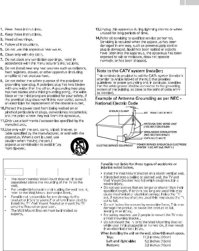
Important Safety Instructions
1.Read these instructions.
2.Keep these instructions.
3.Heed all warnings.
4.Follow all instructions.
5.Do not use this apparatus near water.
6.Clean only with dry cloth.
7.Do not block any ventilation openings. Install
 in accordance with the manufacturer’s instructions.
8.Do not install near any heat sources such as radiators, heat registers, stoves, or other apparatus (including amplifiers) that produce heat.
9.Do not defeat the safety purpose of the polarized or grounding type plug. A polarized plug has two blades with one wider than the other. A grounding type plug has two blades and a third grounding prong. The wide blade or the third prong are provided for your safety. If the provided plug does not fit into your outlet, consult an electrician for replacement of the obsolete outlet.
10.Protect the power cord from being walked on or pinched particularly at plugs, convenience receptacles, and the point where they exit from the apparatus.
11.Only use attachments / accessories specified by the manufacturer.
12.Use only with the cart, stand, tripod, bracket, or table specified by the manufacturer, or sold with the apparatus. When a cart is used, use
caution when moving the cart / apparatus combination to avoid injury from tip-over.
13.Unplug this apparatus during lightning storms or when unused for long periods of time.
14.Refer all servicing to qualified service personnel.
Servicing is required when the apparatus has been damaged in any way, such as power-supply cord or plug is damaged, liquid has been spilled or objects have fallen into the apparatus, the apparatus has been exposed to rain or moisture, does not operate normally, or has been dropped.
Note to the CATV system installer:
This reminder is provided to call the CATV system installer’s attention to Article 820-40 of the NEC that provides guidelines for proper grounding and, in particular, specifies that the cable ground shall be connected to the grounding system of the building, as close to the point of cable entry as practical.
Example of Antenna Grounding as per NEC -
National Electric Code
GROUND CLAMP |
ANTENNA LEAD IN WIRE |
|
|
||
|
ANTENNA DISCHARGE UNIT |
|
|
(NEC SECTION 810-20) |
|
|
GROUNDING CONDUCTORS |
|
|
(NEC SECTION 810-21) |
|
|
GROUND CLAMPS |
|
ELECTRIC SERVICE EQUIPMENT |
POWER SERVICE GROUNDING ELECTRODE |
|
SYSTEM (NEC ART 250, PART H) |
||
|
Wall Mount Bracket Kit |
|
|||
|
Brand |
Model # |
Screw dimension |
|
FW50D36F |
SANUS |
F80B |
M6 x 0.472" (12mm) |
|
VuePoint |
||||
|
|
|
||
5 .English
1 Notice
Declaration of Conformity
Trade Name |
: SANYO |
Responsible Party |
: FUNAI CORPORATION, Inc. |
Model |
: FW50D36F |
Address |
: 19900 Van Ness Avenue, Torrance, CA 90501 |
Telephone Number |
U.S.A. |
: 1 866 212 0436 |
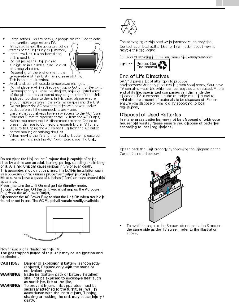
2 Important
Positioning the TV
•Large screen TVs are heavy. 2 people are required to carry
and handle a large screen TV.
• Make sure to hold the upper and bottom  frames of the Unit firmly as illustrated.
• Install
 the Unit in a horizontal and stable position.
•Do not install the Unit in direct
sunlight or in a place subject to dust or strong vibration.
• Depending on the environment, the  temperature of this Unit may increase slightly. This is not a malfunction.
•Avoid a place with drastic temperature changes.
•Do not place anything directly on top or bottom of the Unit.
•Depending on your external devices, noise or disturbance of the picture and / or sound may be generated if the Unit is placed too close to them. In this case, please ensure enough space between the external devices and the Unit.
•Do not insert the AC power cord into the power socket outlet before all the connections are made.
•Ensure that you always have easy access to the AC Power Cord and Outlet to disconnect the TV from the AC Outlet.
•Before you move the TV, disconnect attached Cables to prevent damage to Connectors, especially the TV Tuner.
•Be sure to Unplug the AC Power Plug from the AC outlet before moving or carrying the Unit.
•When moving the TV and then Setting it down, please be careful not to pinch the AC Power Cord under the Unit.
Regulatory Notices
AC Power Plug
6 .English
Environmental Care
Preparing to Move / Ship the Unit
3 Getting Started
Features
● DTV / Analog TV / CATV
You can use your Remote Control to Select channels which are Broadcast in Digital format and conventional Analog format. Also, Cable and Satellite subscribers can access their TV channels.
● Information display
You can display on the TV screen the Title, contents (DTV only) and other information on the current Program.
● Autoprogram
This Unit Automatically scans and memorizes channels available in your area, Eliminating difficult Setup procedures.
● Child lock
This feature allows you to Block children’s access to inappropriate Programs.
● Closed Caption decoder
Built-in Closed Caption decoder displays text for Closed Caption supported Programs.
● MTS / SAP tuner
Audio can be selected from the Remote Control.
● Auto Standby
If there is No Input Signal and No Operation for 15 minutes, the Unit will go into Standby mode Automatically.
● Sleep Timer
You can set the Unit to go into Standby mode after a specific amount of time.
● Choices for On-screen language
Select your On-screen language: English, Spanish or French.
●Stereo sound function
●PLL frequency synthesized tuning
Provides free and easy channel selection and lets you tune directly to any channel using the number and decimal point “•” keys on the Remote Control.
● Various adjustments for Picture and Sound
Customizes picture quality suitable for your room and sets your sound preference.
● HDMI-CEC via HDMI link
HDMI-CEC allows your other HDMI link Devices to be controlled by the HDMI cable connected to your TV.
●HDMI Input
●HDMI-DVI Input
If your Video Device has a DVI Output jack, use an HDMI-DVI Conversion Cable to connect the Unit.
●Component Video Input
●PC Input
Input from a Computer.
● AV Input
Audio and Video Input from an External Device.
● USB terminal
The Picture (JPEG) and Video (Motion JPEG) files stored on a USB Memory Stick can be played back on this Unit.
● Digital Audio Output
Digital Audio (Supporting Dolby Digital) sent to Home Theaters and other Digital Audio systems.
● Headphone Audio Output
Headphone 3.5mm Stereo jack for personal listening.
7 .English
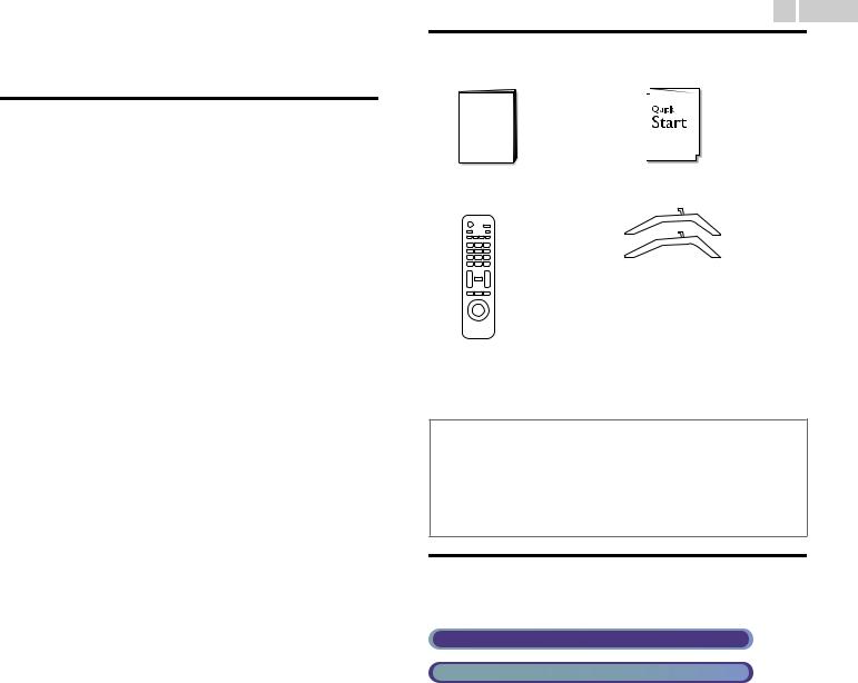
Supplied Accessories
Owner’s Manual |
Quick Start guide |
Remote Control* |
TV base and Screws |
Screws packed with this Unit.
Model |
Quantity |
Size |
FW50D36F |
4 |
M4 x 0.787”(20mm) |
* Batteries not included, AAA 1.5V x 2 Required.
 Note(s)
●If you lose the Screws, please purchase the above-mentioned Phillips head Screws at your local store.
●If you need to replace these accessories, please refer to the Part Name with the illustrations and call our toll free customer support line found on the cover of this Owner’s Manual.
When using a Universal Remote Control to operate this Unit.
●Make sure the component code on your Universal Remote Control is set to our brand. Refer to the instruction book accompanying your Remote Control for more details.
●We Do Not guarantee 100% interoperability with All Universal Remote Controls.
Symbols used in this Owner’s Manual
The following is the description for the symbols used in this Owner’s Manual. Description refers to:
Digital TV Operation
Cable / NTSC (Analog) TV Operation
● If neither symbol appears, the operation is applicable to both.
Continued on next page.
|
|
|
8 |
|
.English |
|
|
|
|
|
|
|
|
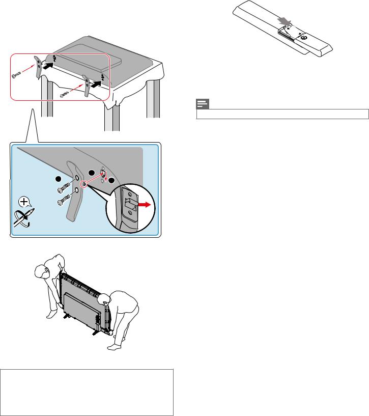
Attaching the Base |
|
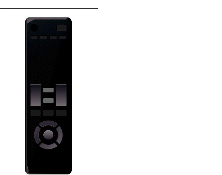
Installing the Remote Control Batteries |
||||
You must attach the base to the Unit to have it as a table top Unit. |
|
|
|
|
|
|
Be sure the front and rear of the base match the proper direction. For |
|
|
|
|
|
|
large screen TVs, at least 2 people are required for these steps. |
|
|
|
|
|
|
1 |
|
|
|
|
|
|
1
2
3
Slide the battery cover off the back of the Remote Control.
Insert 2 Batteries (AAA, 1.5V). Be sure the + and – ends of the Batteries line up with the markings inside the case.
Slide the cover back into position.
Note(s)
● Remove the Batteries if not using the Remote Control for an extended period of time.
3 |
1 |
2 |
× 4
2
 Note(s)
●Make sure to use a table which can support the weight of this Unit and is larger than this Unit.
●Make sure the table is in a stable location.
●When attaching the base, ensure that All Screws are tightly fastened. If the base is not properly attached, it could cause the Unit to fall, resulting in injuries as well as damage to the Unit.
●To remove the base from this Unit, unscrew the Phillips head screws by the reversing procedure. Be careful not to drop the base when you remove it.
Continued on next page.
9 .English
Remote Control
10 |
1 |
11 |
2 |
12 |
3 |
4
aB (POWER / STANDBY)
Turns the TV On from Standby or Off to Standby mode.
bPIC/SOUND MODE
Optimizes Picture and Sound quality.
cCC
Selects Closed caption settings (Off, On, CC w/ mute).
d0 - 9 (NUMBER keys)
Used to enter a Channel / Program number.
• (DOT) |
: Use with 0-9 to Select Digital channels. For example, |
||||||
|
to enter 2.1, press |
||||||
|
|
|
|
|
|
|
|
5
6
7 |
13 |
8 |
14 |
9 |
PREV.CH : Returns to the previously viewed Channel.
CH + / – : Selects a Channel in the Memorized Channel Ring (Low to High or High to Low).
eSAP
Selects Audio mode (MONO / STEREO / SAP) / Audio language.
fVOL + / –
Adjusts the Volume.
gD (MUTE)
Turns the Sound On and Off.
hBACK
Returns to the previous Menu operation.
iHIJK (NAVIGATION keys) / OK
Moves the cursor, Selects the On-screen Menu items.
jSOURCE
Selects Connected Devices.
kSLEEP
Sets Sleep Timer.
lPIX SHAPE A
Adjusts the Picture size on the TV screen.
mINFO
Displays Information about the current program.
nMENU
Opens the Main On-screen Menu.
Use these Keys according to the directions On-screen.
Continued on next page.
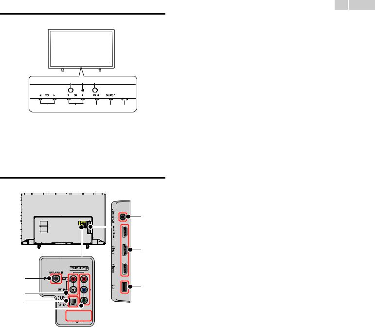
Control Panel
h g f
a b c d e
Terminals
n |
o |
i
p
j k
l


 m
m

10 .English
aVOL J/ K
Adjusts the Volume. In the Menu screen, moves the Cursor Left (J) / Right (K).
VOL J : Volume Down VOL K : Volume Up
bCH H/ I
Selects a Channel. In the Menu screen, moves the Cursor Up (H)/Down (I).
cMENU
Opens the Main On-screen Menu.
dSOURCE
Selects Connected Devices.
eB(POWER)
Turns the TV On and Off.
fRemote Control Sensor
Receives IR signal from Remote control.
gPower On / Standby Indicator
(On : no light, Standby : lights in red)
hAmbient Light Sensor
Alters the brightness of the TV screen automatically by detecting your room lighting level. Do not block this Light Sensor window which allows proper operation.
i75 ohm Cable / Antenna connection
Signal Input from an Antenna or Cable / Satellite Set-top Boxes.
jAnalog Audio (L/R) Input jacks
Connect Analog Audio signals from;
–HDMI-DVI / Analog Audio (L/R) jacks signal
–Component Video / Analog Audio (L/R) jacks signal
–Composite Video / Analog Audio (L/R) jacks signal
–PC Connection / Analog Audio (L/R) jacks signal with Stereo mini 3.5mm plug Audio cable on PC
kDigital Audio Output jack
Digital Audio (S/PDIF) Output to home theaters and other Digital Audio systems.
lComponent (Y/Pb/Pr) / Composite Video (VIDEO) Input jack(s) for
VIDEO
Composite Video Input (VIDEO) jack is a shared jack with Component Video Input (Y) jack.
mPC Input jack
VGA cable connection for PC.
nHeadphone Audio Output jack
Headphone 3.5mm stereo jack for personal listening.
oHDMI Input jack(s)
Digital Audio and Video Input from high definition Digital devices such as DVD / Blu-ray disc players, Cable / Satellite Set-top Boxes, PC’s, etc.
*For HDMI 1 only
In addition to normal HDMI and HDMI-DVI functionality, it outputs TV Audio to an HDMI-ARC-compliant device, such as a home theater system.
pUSB terminal
Data Input from USB Memory Stick only.
Do not connect any device to this terminal such as Digital camera, keyboard, mouse, etc.
Continued on next page.
Connecting the Antenna, Cable or Satellite
Be sure your Antenna or another Device is connected properly before plugging in the AC Power Cord.
If connecting to an Antenna through an RF cable
Any DTV Programs that are Broadcast in your area can be received for free through an Antenna Connection.
 Cable
Cable


 Antenna
IN 


 OUT RF cable
If you connect a Set-top Box through an RF cable
If the TV is connected to a Cable or Set-top Box via a Coaxial Connection, set the TV to channel 3/4 or the channel specified by the service provider.
|
RF cable |
Antenna |
IN |
IN |
OUT |
RF cable |
Set-top Box |
If connecting a Set-top Box through an HDMI cable
If the TV is connected to a Set-top Box via an HDMI cable, make sure you select the correct Source by using SOURCE button on TV or Remote
Control.
 IN
IN
HDMI cable
RF cable
 IN
IN
OUT
Set-top Box
If connecting a Set-top Box through Component Video Input
If the TV is connected to a Cable or Set-top Box via Component Video Input, make sure you select the correct Component Video Source by using SOURCE.
IN |
|
Component (Y/Pb/Pr) |
RF cable |
|
|
|
|||
|
|
Video cables |
|
IN |
|
|
|
|
|
|
IN |
|
OUT |
|
|
|
|
|
|
|
Audio (L/R) cables |
OUT |
Set-top Box |
|
|
|
|
|
|
11 .English
Connecting a Set-top Box, Blu-ray Disc / DVD Recorder via Composite Connectors and Analog Audio
Do Not place your Recorder too close to the Screen because some Recorders can be susceptible to Signals from the TV.
OUT |
Cable |
|
RF cable |
IN Set-top Box |
 IN
IN
RF cable |
OUT |
OUT |
|
Audio (L/R) + |
|
|
Video cables |
|
IN |
OUT |
IN |
Audio (L/R) + Video |
|
|
cables |
|
Blu-ray Disc / |
|
|
DVD Recorder |
 Note(s)
●If you have any question about the DTV’s Antenna, visit www.antennaweb.org for further information.
●Depending on your Antenna system, you may need different types of combiners (mixers) or separators (splitters) for HDTV Signal. The minimum RF bandpass on these Devices is 2, 000MHz or 2GHz.
●For your safety and to avoid damage to this Unit, please unplug the RF Coaxial Cable from the Antenna Input jack before moving the Unit.
●If you did use an Antenna to receive Analog TV, it should also work for DTV reception. Outdoor or attic Antennas will be more effective than a Set-top Box or inside Antenna.
●To Turn On your reception source easily between Antenna and Cable, Install an Antenna selector.
●If you are not receiving a Signal from your Cable service, contact the Cable provider.
●Refer to the Quick Start Guide that shows the connections for the HDMI or Component Input mode.
Plugging in the AC Power Cord
Make sure All the Necessary Connections are made before the AC Power Cord is plugged into an AC outlet.
 Caution(s)
●Connect the Analog Audio signal cables from the external device to the Analog Audio L/R Input jacks.
Or if you have an amplifier, connect the HDMI cable to the HDMI input via your amplifier.
●If you have an amplifier, connect the HDMI cable to the HDMI input via your amplifier.
 Note(s)
●Each time you plug in the AC Power Cord, no operations will be performed for several seconds. This is not a malfunction.
Continued on next page.
No supplied cables are used with these connections:
● Please purchase the Necessary Cables at your local store.
Before you connect the AC Power Cord:
Be sure other Devices are connected properly before plugging in the AC Power Cord.
Selecting your Connection quality
HDMI - Highest quality
Supports High-Definition Digital signals and gives highest picture and sound quality. Video and Audio signals are combined in one cable. You must use HDMI for full High-Definition Video and to enable HDMI-CEC.
 Note(s)
●SANYO HDMI supports HDCP (High-bandwidth Digital Contents Protection). HDCP is a form of Digital Rights Management that protects High-Definition content in Blu-ray Discs or DVDs.
Component (Y Pb Pr) - High quality
Supports High-Definition Analog signals but gives lower picture quality than HDMI. Component (Y/Pb/Pr) Video cables combine red / green / blue Video cables with red / white Audio (L/R) Cables. Match the cable colors when you connect to the TV.
Composite - Basic quality
For Analog Connections. Composite Video / Audio Analog cable usually combine a yellow Video Cable with red / white Audio (L/R) Cables. With this Unit, yellow cable must be connected to Y (green) jack on the Component Video Input jacks.
12 .English
Connecting your Devices
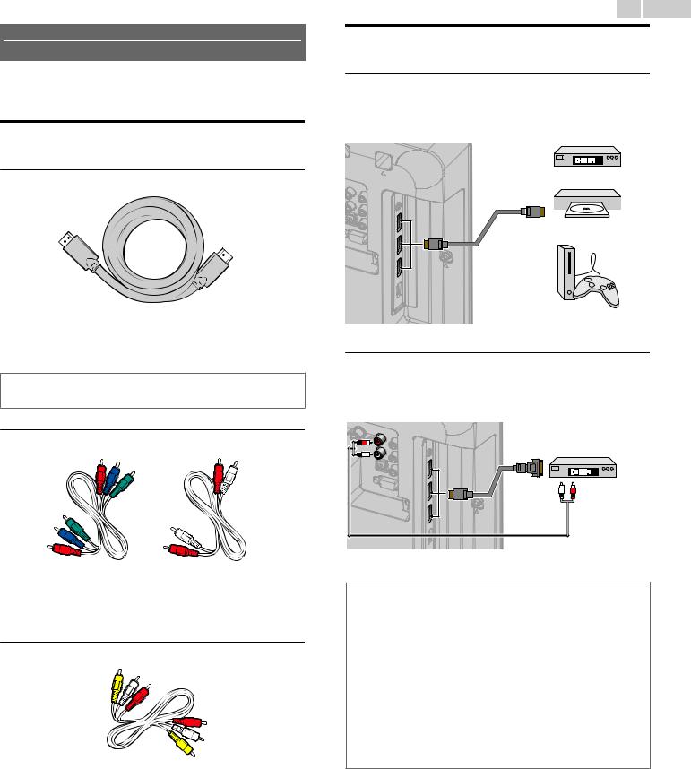
HDMI Digital Connection
HDMI Connection offers the Highest Picture quality.
HDMI (High-Definition Multimedia Interface) transports High-Definition Digital Video and multi-channel Digital Audio through a single cable.
|
Set-top Box |
|
|
or |
|
|
OUT |
|
IN |
Blu-ray Disc / DVD Player |
|
or |
||
|
||
|
HDMI cable |
|
|
HD game console |
HDMI-DVI Connection
This Unit can be connected to your Device that has a DVI Terminal. Use an HDMI-DVI Conversion Cable for this Connection and it requires Audio Cable for Analog Audio signal as well.
|
Cable Receiver or |
|
|
Satellite Set-top Box |
|
|
with the DVI Output jack |
|
IN |
|
|
IN |
OUT |
OUT |
|
HDMI-DVI |
|
conversion cable |
|
|
Audio (L/R) cables
 Note(s)
●Use an HDMI cable with the HDMI logo (a certified HDMI cable). High Speed HDMI cable is recommended for the Better compatibility.
For HDMI Connection
●The Unit accepts 480i / 480p / 720p / 1080i, 1080p 24/30/60Hz of Video signals, 32kHz / 44.1kHz and 48kHz of Audio signals.
●This Unit accepts a 5.1 channel Audio signal (Dolby Digital) and 2 channel Audio signal (LPCM).
●If Audio Source is 7.1 channel Audio signal (Dolby Digital) and user selects Multichannel at Digital output format, then the Digital Audio Output will be 5.1 channel Audio signal (Dolby Digital).
●This Unit accepts only signals in compliance with EIA861.
For HDMI-DVI Connection
●The Unit accepts 480i, 480p, 720p, 1080i and 1080p Video signals.
●HDMI-DVI Connection requires separate Audio Connections as well and the Audio signals are Output as Analog (L/R) Audio.
●DVI does not display 480i image which is not in compliance with EIA/CEA-861/861B.
Continued on next page.
Loading...