


WS80A
Service Manual

SAMSUNG MEDISON
DIAGNOSTIC ULTRASOUND SYSTEM
WS80A
Service Manual
English
SM-WS80A-ENG-02

Safety Requirements
■Categorization
−Type of protection against electric shocks: Class I
−Degree of protection against electric shocks (when the patient is in physical contact): Type BF or type CF applied part
−Degree of protection against the ingress of harmful liquids: General equipment
−Degree of safety of use in the presence of flammable anesthetic agent mixed with air, oxygen, or nitrous oxide: Not suitable for use near flammable anesthetic agent mixed with air, oxygen, or nitrous oxide
−Mode of operation: Continuous operation
■Safety standards the device conforms to
−Medical electrical equipment, part 1: General requirements for basic safety and essential performance IEC 60601-1:2005
−Medical electrical equipment, part 1-2: General requirements for basic safety and essential performance - Collateral standard: Electromagnetic compatibility - Requirements and tests IEC 60601-1-2:2007
−Medical electrical equipment, part 1-6: General requirements for basic safety and essential performance - Collateral standard: Usability IEC
60601-1-6:2010
−Medical electrical equipment, part 2-37: Particular requirements for the basic safety and essential performance of ultrasonic medical diagnostic
and monitoring equipment IEC 60601-2-37:2007
−Medical electrical equipment, part 1: General requirements for safety IEC
60601-1:1988, A1:1991, A2:1995
−Medical electrical equipment, part 1-1: General requirements for safety - Collateral standards: General requirements for medical electrical systems
IEC 60601-1-1:2000
−Medical electrical equipment, part 1-2: General requirements for safety - Collateral standards: Electromagnetic compatibility - Requirements and tests IEC 60601-1-2:2001, A1:2004
−Medical electrical equipment, part 1-4: General requirements for safety - Collateral standards: Programmable electrical medical systems IEC
60601-1-4:1996, A1:1999

−Medical electrical equipment, part 2-37: Particular requirements for the basic safety and essential performance of ultrasonic medical diagnostic and monitoring equipment IEC 60601-2-37:2001, A1:2004, A2:2005
−Medical devices - Application of risk management to medical devices ISO
14971:2007
−Medical electrical equipment, part 1: General requirements for safety UL
60601-1:2003
−Medical electrical equipment - part 1: General requirements for safety
CAN/CSA C22.2 No. 601.1-M90:1990, R2003, R2005
−Biological evaluation of medical devices – part 1: evaluation and testing
ISO 10993-1: 2009
−Standard means for reporting the acoustic output of medical diagnostic ultrasonic equipment IEC 61157:2007
■Statements
This is the CSA symbol used in Canada and the
United States.
This mark certifies that the product conforms to applicable EEC standards and has been certified by the European certification agency.
This mark certifies that the product conforms to applicable EEC standards.
GMP symbol represents the good manufacturing practice and quality standards in accordance with the Korean Quality Standards.

Precautions for Use
Be sure to read this operation manual thoroughly, to familiarize yourself with the operation of the product and the relevant safety information, before attempting to use the product.
■Keep this manual near the product and refer to it when using the product.
■Please familiarize yourself with the safety precautions in 'Chapter 1. Safety' and 'Chapter 8. Maintenance' in particular.
■This operation manual does not contain clinical opinions or diagnoses. Also, please consult the reference for each study area before evaluating the measurement result of an application.
■This product is an ultrasound diagnostic system, and cannot be used with your personal computer. If you use this product in such an environment, we cannot be held responsible for any resulting problems.
■This product must be used by a person who possesses clinical pathology training and/or certification; use by unqualified persons is prohibited.
■The manufacturer is not responsible for any damage to this product caused by user carelessness and/or neglect.
■The contents of this operation manual may be changed without notice.
■Products that are not manufactured by Samsung Medison are indicated with the trademarks of their respective owners.
■The following terms are used to highlight safety precautions that the user must be aware of:
DANGER
WARNING
CAUTION
NOTE
Disregarding this instruction may result in death, serious injury, or other dangerous situations.
Follow these instructions to prevent a serious accident or damage to property.
Follow these instructions to prevent a minor accident or damage to property.
The accompanying information covers an installation, operation, or maintenance procedure that requires careful attention from the user, but has little chance of leading directly to a dangerous situation.

Revision History
The revision history of this manual is as follows.
VERSION |
DATE |
NOTE |
|
|
|
V3.00.00-00 |
2015.10.30 |
Initial Release |
|
|
|
System Upgrades and Manual Set Updates
Samsung Medison Ultrasound is committed to innovation and continued improvement. Upgrades may be announced that consist of hardware or software improvements. Updated manuals will accompany those system upgrades. Verify that Check if this version of the manual is correct for the system version. If not, please contact the Customer Service Department.
If You Need Assistance
If you need any assistance with the equipment, like the service manual, please contact the Samsung Medison Customer Service Department or one of their worldwide customer service representatives, immediately.
Table of Contents |
1 |
Table of Contents
Chapter 1. Introduction |
|
Product Specifications .......................................................................................................... |
2 |
Product Configuration........................................................................................................... |
5 |
The Monitor ..................................................................................................................... |
7 |
The Control Panel ........................................................................................................... |
9 |
The Console .................................................................................................................... |
16 |
Peripheral Devices .......................................................................................................... |
18 |
Probes ............................................................................................................................. |
21 |
Accessories ..................................................................................................................... |
22 |
Optional Functions .......................................................................................................... |
23 |
Chapter 2. Safety |
|
Purpose of Use....................................................................................................................... |
2 |
Safety Information.................................................................................................................. |
3 |
Safety Symbols................................................................................................................ |
3 |
Symbols........................................................................................................................... |
6 |
LABEL ............................................................................................................................. |
7 |
Electrical Safety ..................................................................................................................... |
8 |
Prevention of Electric Shocks.......................................................................................... |
8 |
ECG-related Information ................................................................................................. |
10 |
ESD ................................................................................................................................. |
10 |
EMI .................................................................................................................................. |
11 |
EMC................................................................................................................................. |
11 |
Biological Safety .................................................................................................................... |
23 |
ALARA Principle.............................................................................................................. |
23 |
Environmental Protection ..................................................................................................... |
38 |
Correct Disposal of This Product(Waste Electrical & Electric Equipment) ..................... |
38 |
2 WS80A Service Manual
Chapter 3. Installing the Product |
|
Unpacking the Product ......................................................................................................... |
3 |
Installation Environment....................................................................................................... |
4 |
Installing the Product............................................................................................................ |
5 |
Power Cord Connection.................................................................................................. |
6 |
Probe Connection ........................................................................................................... |
6 |
Connecting Peripherals .................................................................................................. |
7 |
System Power ........................................................................................................................ |
9 |
Turning the Power On..................................................................................................... |
9 |
Shutting Down the System.............................................................................................. |
10 |
System Settings..................................................................................................................... |
11 |
System General Setting .................................................................................................. |
12 |
Scan Mode...................................................................................................................... |
17 |
Display ............................................................................................................................ |
21 |
Annotate.......................................................................................................................... |
26 |
Peripheral Device Settings ............................................................................................. |
31 |
User Defined Keys .......................................................................................................... |
38 |
MPR Menu ...................................................................................................................... |
40 |
Network........................................................................................................................... |
41 |
Options............................................................................................................................ |
43 |
DICOM Setup (optional).................................................................................................. |
45 |
Auto Calc......................................................................................................................... |
59 |
System Information ......................................................................................................... |
60 |
Chapter 4. Product Inspection |
|
Inspecting Functions ............................................................................................................ |
2 |
Basic Inspections ............................................................................................................ |
2 |
Detailed Inspections........................................................................................................ |
4 |

|
Table of Contents 3 |
Chapter 5. Product Structure |
|
Overview ................................................................................................................................. |
3 |
System Block Diagram .......................................................................................................... |
5 |
Basic Structure of UGEO WS80A......................................................................................... |
7 |
Overview.......................................................................................................................... |
7 |
Ultrasound System Part .................................................................................................. |
8 |
PC Part ............................................................................................................................ |
9 |
User Interface Part .......................................................................................................... |
10 |
AC to Power Module ....................................................................................................... |
10 |
Ultrasound System Part ........................................................................................................ |
11 |
PSA ................................................................................................................................. |
11 |
Analog Control................................................................................................................. |
13 |
Beam Former Board........................................................................................................ |
15 |
Back End Board .............................................................................................................. |
19 |
PC Part .................................................................................................................................... |
24 |
PC Module....................................................................................................................... |
24 |
Software DSC.................................................................................................................. |
25 |
Rear Board ...................................................................................................................... |
27 |
Power Supply .................................................................................................................. |
28 |
User Interface Part ................................................................................................................. |
31 |
Control Panel................................................................................................................... |
31 |
Docking CP Board........................................................................................................... |
33 |
Touch Panel .................................................................................................................... |
34 |
Monitor............................................................................................................................. |
35 |
Chapter 6. Service Mode |
|
System Information................................................................................................................ |
2 |
Windows Mode....................................................................................................................... |
3 |

4 WS80A Service Manual
Admin Mode ........................................................................................................................... |
4 |
Admin Mode Functions ................................................................................................... |
5 |
Adding and Deleting Options............................................................................................... |
11 |
Adding an Option ............................................................................................................ |
12 |
Chapter 7. Troubleshooting |
|
Power Issues.......................................................................................................................... |
2 |
Power Does Not Turn On ............................................................................................... |
2 |
Power Does Not Turn Off................................................................................................ |
2 |
Power Turns Off by Itself ................................................................................................ |
3 |
Monitor.................................................................................................................................... |
4 |
Nothing Is Displayed on the Screen ............................................................................... |
4 |
Screen is Discolored....................................................................................................... |
4 |
Error Messages...................................................................................................................... |
5 |
Error Occurs during Booting ........................................................................................... |
5 |
Image ...................................................................................................................................... |
6 |
2D Mode: There is No IMAGE ECHO or IMAGE FORMAT ........................................... |
6 |
Lines (Noise) Appear in 2D Mode Image ....................................................................... |
6 |
M, C, PW, CW Mode Trouble ......................................................................................... |
6 |
Error Code .............................................................................................................................. |
7 |
Chapter 8. Disassembly and Assembly |
|
Caution ................................................................................................................................... |
2 |
Preparation ..................................................................................................................... |
2 |
Disassembling the Product .................................................................................................. |
3 |
Front Cover Disassembly ............................................................................................... |
3 |
Rear Cover Disassembly ................................................................................................ |
5 |
Control Panel Disassembly............................................................................................. |
7 |
Monitor Disassembly....................................................................................................... |
8 |

|
Table of Contents 5 |
Monitor Arm Disassembly ............................................................................................... |
9 |
Assembling the Product........................................................................................................ |
11 |
Chapter 9. Probes |
|
Probe ....................................................................................................................................... |
2 |
Ultrasound Transmission Gel.......................................................................................... |
15 |
Using Sheaths ................................................................................................................. |
16 |
Probe Safety Precautions................................................................................................ |
17 |
Cleaning and Disinfecting the Probe............................................................................... |
19 |
Chapter 10. Maintenance |
|
Product Maintenance............................................................................................................. |
2 |
Cleaning and disinfecting ................................................................................................ |
2 |
Air Filter Management ..................................................................................................... |
4 |
Accuracy Checks............................................................................................................. |
5 |
Information Maintenance ...................................................................................................... |
6 |
Backing up User Setting.................................................................................................. |
6 |
Backing Up Patient Information....................................................................................... |
6 |
Software .......................................................................................................................... |
6 |
Chapter 11. Service Part List |
|
Body Cover Parts .............................................................................................................. |
2 |
System Parts ..................................................................................................................... |
7 |
Control Panel Parts........................................................................................................... |
11 |
System Cable Parts........................................................................................................... |
14 |

Chapter 1
Introduction |
|
Product Specifications.................................................................................................. |
2 |
Product Configuration .................................................................................................. |
5 |
The Monitor............................................................................................................................... |
7 |
The Control Panel..................................................................................................................... |
9 |
The Console ........................................................................................................................... |
16 |
Peripheral Devices.................................................................................................................. |
18 |
Probes..................................................................................................................................... |
21 |
Accessories ............................................................................................................................ |
22 |
Optional Functions.................................................................................................................. |
23 |

1 - 2 WS80A Service Manual
Product Specifications
Physical
Dimensions
Imaging
modes
Gray Scale
Focusing
Probes
(Type BF / IPX7)
Height: 1,430 – 1,710mm (with monitor)
Width: 557mm
Depth: 791 – 860mm
Weight: 105.4kg (with monitor)
Weight: Approx. 130kg (with Safe Working Load)
2D-Mode M-Mode Color Doppler
Pulsed Wave (PW) Spectral Doppler Continuous Wave (CW) Spectral Doppler Tissue Doppler Imaging (TDI)
Tissue Doppler Wave (TDW) Power Doppler (PD)
Directional Power Doppler (S-Flow) Color M-Mode
Anatomical M mode 3D imaging Mode 4D imaging Mode ElastoScan Mode
256 (8 bits)
Transmit focusing, maximum of eight points (four points simultaneously selectable)
Digital dynamic receive focusing (continuous)
Linear Array
L3-12A, L5-13, LA2-9A, LA3-16A, LA3-16AI, LA4-18B
Convex
C2-6, CA1-7A, CA2-8A, CA2-9A, CA3-10A, CF4-9, SC1-6
Endocavity
E3-12A, EA2-11B, VR5-9
Phased Array
PA3-8B, PE2-4, PM1-6A

Chapter 1. Introduction 1 - 3
Probe connections
Monitor
ECG
Rear Panel
Input / Output
Connections
Image
Storage
Application
Electrical
Parameters
Measurement
Packages
Signal processing (Pre-processing)
3D
CV1-8A, LV3-14A, V4-8, V5-9
Five Active Probe Ports (include one CW probe port)
Main Monitor
23 inch Full HD LCD monitor (LED backlight unit) called "LCD monitor" henceforth
Touch Screen Monitor
10.1 inch LCD monitor (LED backlight unit) called "LCD monitor" henceforth
USB Type (Type CF)
Audio in / out
Microphone
External Trigger in / out
External monitor DVI-I
Network
USB
Foot Switch
Maximum 12,700 frames for Cine memory
Maximum 8,192 lines for LOOP memory
Image filing system
Obstetrics, Gynecology, Urology, Abdomen, Vascular, Small Part, MSK, Pediatric, Cardiac, TCD, Intraoperative
100-240V~, 1100VA, 50/60Hz
OB, Gynecology, Cardiac, Vascular, Fetal Heart, Urology, Abdomen, Small Parts, MSK, TCD, Pediatric Hips
* Refer the Chapter 9 for additional information
TGC Control (Digital / Slider)
Mode-independent gain control
Acoustic power control (adjustable)

1 - 4 WS80A Service Manual
Signal processing (Post-processing)
Measurement
Auxiliary
User Interface
Pressure Limits
Humidity Limits
Temperature Limits
Dynamic aperture
Dynamic apodization
Dynamic range control (adjustable)
Image view area control
M-mode sweep speed control
Frame average
Edge Enhancement / Blurring
Gamma-scale windowing
Image orientation (left/right and up/down, rotation)
White on black/black on white
Zoom
Trackball operation of multiple cursors
2D mode: Linear measurements and area measurements using elliptical approximation or trace
M mode: Continuous readout of distance, time, and slope rate Doppler mode: Velocity and trace
USB Video Printer
USB to RS-232 Serial Cable
Foot Switch(IPX8)
USB Flash Memory Media
USB HDD
Monitor
English, German, French, Spanish, Italian, Russian, Chinese
Operating: 700 – 1,060hPa
Storage: 700 – 1,060hPa
Operating: 30 – 75%
Storage & Shipping: 20 – 90%
Operating: 10 – 35OC
Storage & Shipping: -25 – 60OC

Chapter 1. Introduction 1 - 5
Product Configuration
This Product consists of monitor, control panel, console, peripheral devices and probes.
Monitor
Monitor armDVD driveSpeaker
Control panelProbe holderKeyboard
Lift
USBport
CW probe port
Probe port
Air filter
Brake
Wheels
Touch panel
Gel Warmer (Option)
[Figure 1.1 Front of the product]

1 - 6 WS80A Service Manual
Handle
Storage compartmentsVentilation
Rear panelCable hook
Power terminalID Label
[Figure 1.2 Back of the product]
Chapter 1. Introduction 1 - 7
The Monitor
Ultrasound images and other information are displayed on the color LCD monitor.
▐ Screen Layout
The screen displays ultrasound images, operation menus and a variety of other information. The main areas of the screen are Title Area, Preset Change and EZ Exam Area, Image Area, Thumbnail Area, User Information Area, and User Defined Key Area, as shown below.
[Figure 1.3 Screen Layout]
Title Area
Displays patient name, hospital name, application, frame rate and depth, probe information, acoustic output information, and date and time.
Preset Change and Ez Exam+ Area
Displays Preset Change. You can quickly change the preset of a probe. The Ez Exam+ menu will also appear if being used.
You can set up the Ez Exam+ at Ez Exam+ Setup; please refer to ‘Chapter 3. Utilities’ for information on Ez Exam+ Setup.
NOTE

1 - 8 WS80A Service Manual
Image Area
Displays ultrasound images, TGC, image information, annotation, and measurement information are also displayed.
Thumbnail Area
Images saved by selecting Save are displayed as thumbnails. If saving Single screens, up to 5 images are shown in a list; for Quad screens, up to 16 images are displayed. Clicking with the pointer will enlarge the selected thumbnail in the Image area.
User Information Area
Information that is useful to the user, such as current system status, image information, selectable items, etc., is displayed.
User Defined Key Area
Settings for User Defined Keys, including the positions of Set and Exit, are displayed. You can change the setting of each button in Setup > User Defined Key.
|
|
NOTE |
|
For information on User Key Setup, please refer to 'Chapter 3. |
|
|
|
Utilities'. |
|
|
|
|
|
|
|
|
|
|
|
TIP |
|
Principles of Operation of the Diagnostic Ultrasound System |
||
|
|
Medical ultrasound images are created when the computer's digital memory |
||
|
|
converts the high-frequency wave signals that are transmitted and received by the |
||
|
|
probe. |
|
|
As ultrasound waves propagate through the human body, they generate reflected signals whenever they encounter a change in density. For example, reflected signals are generated when signals pass from fatty tissues to muscle tissues. Reflected signals return to the probe where they are converted into electronic signals. The reflected signals are amplified and processed by analog and digital circuits that have filters for various frequencies and response time options. Then they are again converted into high-frequency electronic signals, and saved as a series of digital image signals. The monitor displays the image signals stored on the storage device in real time.
The entire process of transmitting, receiving, and processing signals is controlled by the computer.
Chapter 1. Introduction 1 - 9
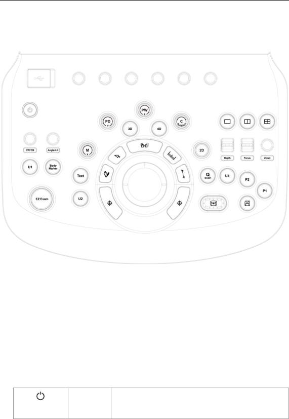
The Control Panel
The system can be controlled by using the control panel.
[Figure 1.4 Control Panel]
The control panel consists of a keyboard, soft menus, buttons, dials, dial-buttons, a slider, and a trackball.
The dial-button can be used both as a dial and a button.
▐ Functions of the Control Panel
The followings describe each control in the control panel and show how to use them. Controls with multiple functions are described in detail in the following chapters of Chapter 3 in this manual.
Button |
Turns the system on/off. |
On/Off

1 - 10 WS80A Service Manual
2D |
Dial-button |
Button: Starts 2D mode. |
|
Dial: Adjusts the 2D gain. |
|||
|
|
||
|
|
|
|
|
|
Button: Starts or ends M mode. |
|
M / x |
Dial-button |
Dial: Adjusts M gain. Also, turning this dial-button when in 3D |
|
|
|
View rotates the image along the x-axis. |
|
|
|
Button: Starts or ends Power Doppler mode. |
|
PD / y |
Dial-button |
Dial: Adjusts the PD gain. Also, turning this dial-button, when in |
|
|
|
3D View rotates the image along the y-axis. |
|
|
|
Button: Starts or ends PW Spectral Doppler mode. |
|
PW / z |
Dial-button |
Dial: Adjusts the PW gain. Also, turning this dial-button when in |
|
|
|
3D View rotates the image along the z-axis. |
|
|
|
|
|
|
|
Button: Starts or ends Color Doppler mode. |
|
C / Ref. Slice |
Dial-button |
Dial: Adjusts the C gain. Moves the reference slice horizontally in |
|
|
|
3D View. |
|
|
|
|
|
3D |
Button |
Starts or ends 3D mode. |
|
|
|
|
|
4D |
Button |
Starts or ends 4D mode. |
|
|
|
|
|
|
|
Button: Starts or ends CW Spectral Doppler mode. |
|
CW / TB |
Dial-button |
Dial: Adjusts the CW gain. Adjusts top and bottom margins of |
|
|
|
ROI in 3D View-MPR. TB is an abbreviation for “Top-Bottom”. |
|
|
|
Button: Adjusts the angle of the sample volume in Spectral |
|
|
|
Doppler mode. It is also used to adjust the BodyMarker’s probe |
|
Angle / LR |
Dial-button |
cursor or indicator angle. |
|
|
|
Dial: Adjusts left and right margins of ROI in 3D View-MPR. LR is |
|
|
|
an abbreviation for “Left-Right”. |
|
|
|
|
|
Depth |
Switch |
Adjusts the scanning depth of the image. |
|
|
|
|
|
Focus |
Switch |
Changes location and number of focus on the target location you |
|
wish to study. |
|||
|
|
||
Zoom |
Dial-button |
You can magnify an image. |
|
|
|
|
|
Q Scan |
Button |
Press this button to turn the Quick Scan function on. The ‘Q |
|
Scan’ mark will appear at the top of an image. |
|||
|
|
||
|
|
|
|
Freeze |
Button |
Pauses/resumes scanning. |
|
|
|
|
|
Save |
Button |
Saves an image or a report displayed on the screen to the |
|
database. |
|||
|
|
||
|
|
|

|
|
|
Chapter 1. Introduction |
1 - 11 |
|
|
|
|
|
|
|
|
Stands for ‘User Key.’ This button allows users to select a |
|
|
U1, 2, 4 |
Button |
function to apply to the button. The function of each button can |
|
|
be set in Setup > User Defined Key. The selected settings will be |
|||
|
|
|
displayed in the User Defined Key area of the monitor. |
|
|
|
|
|
|
|
|
|
Stands for ‘Peripheral Key.’ This button allows users to select a |
|
|
P 1~2 |
Button |
function to apply to the button. The function of each button can |
|
|
be set in Setup > User Defined Key. The selected settings will be |
|||
|
|
|
displayed in the User Defined Key area of the monitor. |
|
|
|
|
|
|
|
BodyMarker |
Button |
Allows the user to enter a BodyMarker over an image. |
|
|
|
|
|
|
|
Text |
Button |
Allows the user to place text on an image. |
|
|
|
|
|
|
|
EZ Exam |
Dial-button |
Use the EZ Exam and Preset Change features. |
|
|
|
|
|
|
|
|
Button |
In this mode, only the image is displayed on the screen. |
|
|
|
|
|
|
|
|
|
|
|
|
|
Button |
Compares two independent images. |
|
|
|
|
|
|
|
|
|
|
|
|
|
Button |
Compares four independent images. |
|
|
|
|
|
|
|
|
|
|
|
|
|
|
This button is used to assign user-defined functions. The |
|
|
|
|
function of each button can be set in Utility > Setup > User |
|
|
|
|
Defined Key. |
|
|
Set / Exit |
Button |
Set: Selects an item or value using the trackball or changes the |
|
|
|
function of the trackball. |
|
|
|
|
|
|
|
|
|
|
Exit: Exits the function currently being used and returns to the |
|
|
|
|
previous state. |
|
|
|
Button |
When this is pressed, an arrow marker appears to point to parts |
|
|
Pointer |
of the displayed image. |
|
|
|
|
|
||
|
|
|
|
|
|
|
Button |
Deletes text, indicator, BodyMarker, and measurement result, |
|
|
Clear |
etc. displayed on an image. |
|
|
|
|
|
||
|
Change |
Button |
This is used to change the current trackball function. |
|
|
|
|
|
|
|
Calculator |
Button |
Starts measurements by application. |
|
|
|
|
|
|
|
Caliper |
Button |
Starts to measure distance, circumference, area, and volume. |
|
|
|
|
|
|
|
|
|
|
|
|
Trackball |
Trackball |
Moves the cursor on the screen and scrolls through |
Cine |
|
images. |
|
||
|
|
|
|
|
|
|
|
|
|
1 - 12 WS80A Service Manual
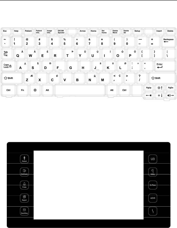
Keyboard
The keyboard is used to type in text.
[Figure 1.5 Keyboard]
▐ Touch Panel
These control tools are located on both sides of the touch screen. Available buttons are as follows:
[Figure 1.6 Touch Panel]

|
|
Chapter 1. Introduction 1 - 13 |
|
|
|
|
|
|
Patient |
Displays the Patient Information screen, which is used for selecting a patient |
|
|
ID from the list or entering new patient information. |
|
|
|
|
|
|
|
|
|
|
|
End Exam |
Finishes the exam of the currently selected patient and resets the related |
|
|
data. |
|
|
|
|
|
|
|
|
|
|
|
Probe |
Displays the Probe Selection screen to select or change the probe and |
|
|
application. |
|
|
|
|
|
|
|
|
|
|
|
Report |
Displays the Report screen that shows the measurement results of the |
|
|
current application and other information. |
|
|
|
|
|
|
|
|
|
|
|
SonoView |
Runs SonoView, which is the image filing program. |
|
|
|
|
|
|
|
Stands for User Key; functions can be assigned to these buttons as desired. |
|
|
U3 |
The function of each button can be set in Setup > User Defined Key. The |
|
|
|
settings are displayed in the User Defined Key area in the monitor. |
|
|
|
|
|
|
Utility |
The Utility Menu appears on the touch screen. |
|
|
|
|
|
|
S-Flow |
Initiates or terminates the S-Flow (Directional Power Doppler) Mode. |
|
|
|
|
|
|
ADVR |
Initiates recording feature. |
|
|
|
|
|
|
TGC |
The TGC screen will be displayed on the touch screen. TGC stands for Time |
|
|
Gain Compensation. |
|
|
|
|
|
|
|
|
|
|

1 - 14 WS80A Service Manual
▐ Touch Screen
[Figure 1.7 Touch Screen]
The touch screen is an operating tool that can be touched by the user to input data. The functions that are available in the current mode are shown in the form of buttons or a dial-button.
■Touch screen display
Information Area: Shows the title of the touch screen currently displayed.
Tab Area: Shows diagnostic modes and utilities under different tabs. The touch screen can be changed by pressing one of the tabs.
Menu Area: The menu items that are available in the current input mode are shown in the form of buttons. The user can access the desired menu item by pressing the corresponding button. The menu currently in use is shown in blue.
Soft Menu Area: The soft menu items that are available in the current input mode are shown.The menus in use are shown with blue borders. Press or rotate the dial-buttons right below each menu.
Quick Preset: With predefined diagnosis mode and presets of probes frequently used by the user, this function provides quick and easy access to frequently used probe in each diagnosis mode
For further details about setting up Quick Preset, please refer to ‘Setup > General > Quick Preset > Quick Preset Setup’ in ‘Chapter 3 Utilities’.
NOTE

Chapter 1. Introduction 1 - 15
Tip! When there are two Soft Menus
When there are two menus available – upper and lower, both menus can be adjusted with the corresponding dial-button. Or tap the button for the menu you want to use on the touch screen and then use the dial-button.
▐ Adjusting the Control Panel
CAUTION
Do not apply excessive force to the control panel.
Use the handle at the back of the product when moving it.
Adjust right/left
Hold the control panel handle and move it carefully to the right or left.
Adjust up/down
Press the lever on the control panel handle and move it carefully up or down.

1 - 16 WS80A Service Manual
The Console
The console consists of two parts – the inner and outer units. The inside of the console contains ultrasound imaging components. On the exterior of the console are various connectors, probe holders, storage compartments, handles, and wheels, etc.
▐ Rear Panel
Various peripheral devices including monitors are connected via the rear panel at the back of the system.
|
|
Trig port (In/Out): Not used. |
|
Microphone port (Input): Connect a microphone to |
|||
|
|
||
|
|
this port. |
|
|
|
VHS port (Output): Outputs composite image to the |
|
|
|
monitor. |
|
|
Audio port (Output): Used to output audio signals. |
||
|
|
||
|
S-VHS port (Output): Outputs S-VHS image to the |
||
|
|
monitor. |
|
|
|
DVI port (Output): Outputs the digital signal (DVI |
|
|
Full HD) and analog signal (DVI R.G.B) to the |
||
|
|
||
|
|
monitor. |
|
|
|
USB port: Used to connect to USB peripheral |
|
|
|
devices.. |
Network port: Used to connect to a network. You
|
can transfer patient information to another server |
|
via the DICOM network. |
[Figure 1.9 Rear panel]
 Loading...