

Samsung SYNCMASTER 400UXN-3, 460UXN-3, 460UX-3, SYNCMASTER 400UX-3 User Manual

LCD MONITOR
quick start guide
400UXN-3 400UX-3 460UXN-3 460UX-3
ii

Introduction
Package Contents
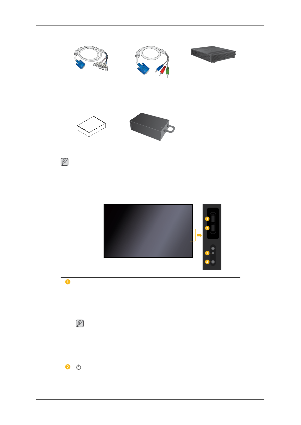
Checking the Contents of the Package
Remove the lock from the package box, as shown in the figure above.
Lift up the package box by
both sides of the package
• After unpacking the package, make sure to check the contents of the package.
• Store the packaging box in case you need to move the Product later.
• If any items are missing, contact your dealer.
• Contact a local dealer to purchase optional items.
Unpacking
holding the grooves on
box.
Note
Check the contents of the
package.
Remove the Styrofoam
and vinyl cover.
LCD Display

Manuals
Introduction
Quick Setup Guide Warranty Card
(Not available in all loca-
tions)
MagicInfo Software CD,
MagicInfo Manual CD
(Applicable to the
400UXN-3, 460UXN-3
model only)
Cables
Power Cord D-Sub Cable
Others
User's Guide
Remote Control
(BP59-00138B)
Sold separately
Semi Stand KIT LAN Cable USB Cable
Batteries (AAA X 2)
(Not available in all loca-
tions)
(Applicable to the
400UXN-3, 460UXN-3
model only)
Introduction
Sold separately
RGB to BNC Cable RGB to Component Cable Network Box
(Applicable to the
400UX-3, 460UX-3 model
Wall Mount KIT TV Tuner Box
Note
only)
Accessories that can be purchased with the product vary by country.
Your LCD Display
Front
SOURCE button
Switches from PC mode to Video mode. Selects the input source that an
external device is connected to.
[PC] → [DVI] → [AV] → [Component] → [HDMI1] → [HDMI2] → [Dis-
playPort] → [MagicInfo] → [TV]
Note
• A TV tuner box (sold separately) must be connected to use the TV.
• A network box (sold separately) must be connected to use MagicInfo
with a 400UX-3, 460UX-3 model.
POWER button
Use this button for turning the LCD Display on and off.
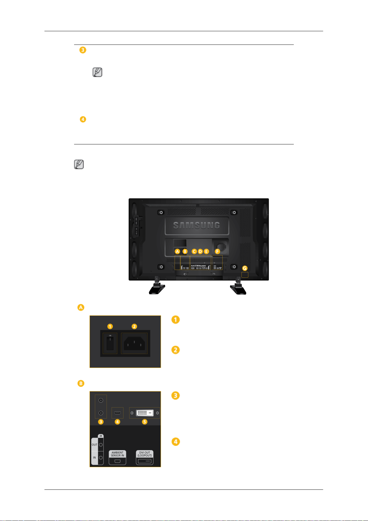
Rear
Introduction
Power indicator
Shows PowerSaver mode by blinking green
Note
See PowerSaver described in the manual for further information regarding
power saving functions. For energy conservation, turn your LCD Display
OFF when it is not needed or when leaving it unattended for long periods.
Remote Control Sensor
Aim the remote control towards this spot on the LCD Display.
Note
See the "Connections" section for details about cable connections. The LCD Display's configuration at the back may vary slightly depending on the model.
POWER S/W ON [ │ ] / OFF
Switches the LCD Display On/Off.
POWER
The power cord plugs into the LCD Display
and the wall outlet.
IR OUT/IN
Receives a signal from the remote control
and outputs the signal through Loopout when
a removable sensor board is connected.
AMBIENT SENSOR IN
Supplies power to the removable sensor
board and receives a signal from the light
sensor.
Introduction
DVI OUT (LOOPOUT)
• Connect a monitor to another monitor
through a DVI, DVI to HDMI cable.
• Connect a DVI or DVI-HDMI cable to [DVI
OUT (LOOPOUT)] on the product and
[DVI IN] or [HDMI IN] on another monitor.
• HDMI and network signals sent via the
[DVI OUT(LOOPOUT)] port are displayed on the second display which has
the [DVI IN] port.
Note
• The Loopout function can be used to duplicate the screen of the primary display.
Connect [
play to [DVI IN] or [HDMI] on another
display.
DVI OUT] on the primary dis-
• A maximum of 100 monitors can be connected to DVI-Loopout (using a 2m-long
DVI cable). Up to HD resolution can be
supported. Compatible input sources include DVI IN, HDMI IN 1, and HDMI IN 2
(MagicInfo).
• The status of the cable may have a great
effect on the Loopout performance.
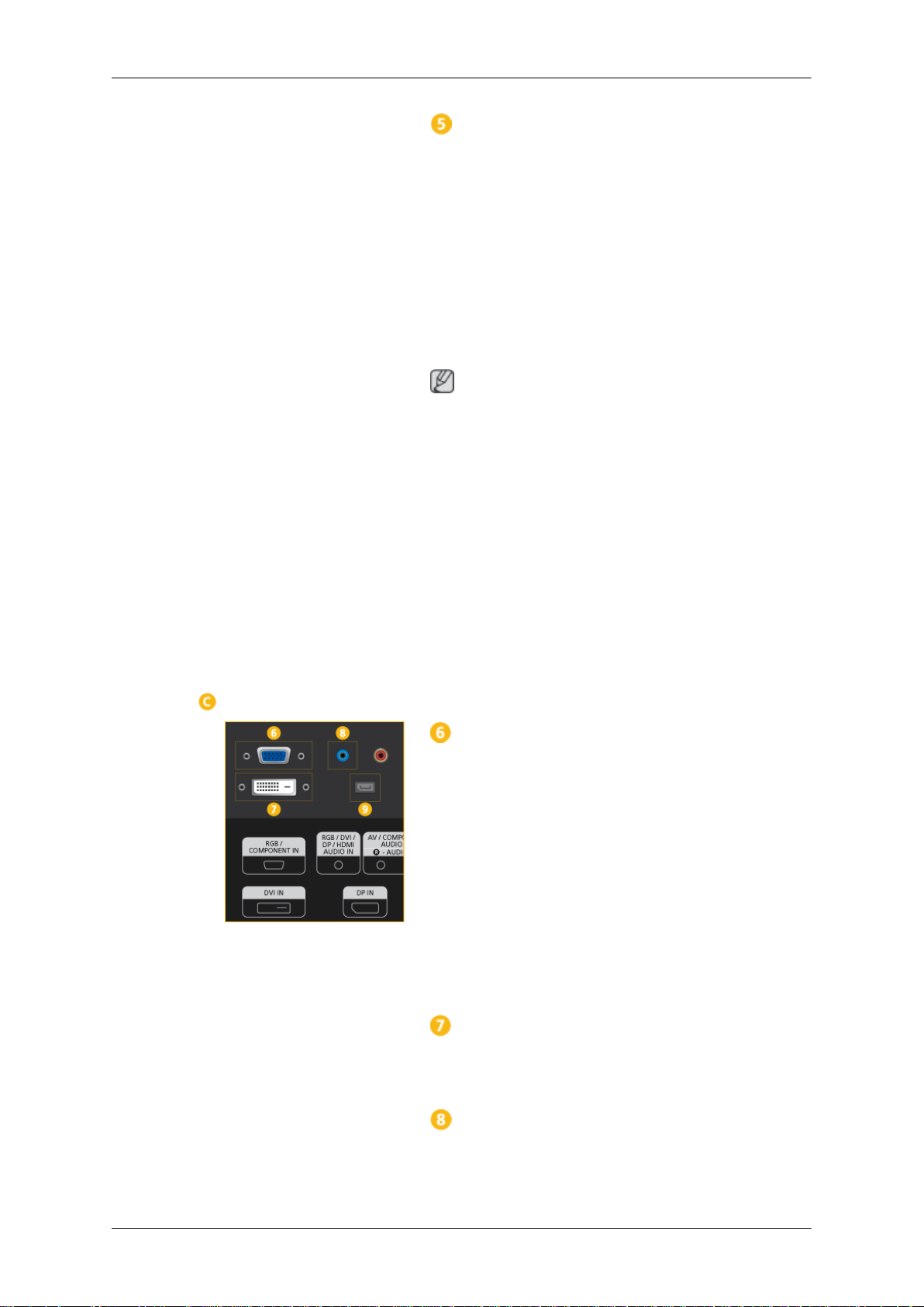
RGB/COMPONENT IN (PC/COMPO-
NENT Connection Terminal (Input))
• Connect the [RGB/COMPONENT IN]
port on the monitor to the RGB port on the
PC using the D-SUB cable.
• Connect the [RGB/COMPONENT IN]
port on the monitor to the COMPONENT
port on the external device using the RGB
to COMPONENT cable.
• Connect the [RGB/COMPONENT IN]
port on the monitor to the BNC port on the
PC using the RGB to BNC cable.
DVI IN (PC Video Connection Terminal)
Connect the [DVI IN] port on the monitor to
the DVI port on the PC using the DVI cable.
RGB/DVI/DP/HDMI AUDIO IN (PC/DVI/
DP/HDMI Audio Connection Terminal (Input))

Introduction
Connect the [RGB/DVI/DP/HDMI AUDIO
IN] terminal of the monitor and the speaker
output terminal of your computer's sound
card using a stereo cable (sold separately).
DP IN
Receives a signal from the Display port.
Connect a DP cable to [DP IN] on the product
and DP IN on another display.
AV/COMPONENT AUDIO IN [R-AUDIO-
L]
Connect the [AV/COMPONENT [R-AUDIO-
L]] port on the monitor to the audio output
port on the PC or on the external device using an audio cable.
AV IN
Connect the [AV IN] terminal of your monitor
to the video output terminal of the external
device using a VIDEO cable.
AUDIO OUT
Connect a headphone or an External speak-
er.
DC OUT
Make sure to use connecting [DC OUT] ter-
minal to the authorized TV-Tuner Box
[SBB_DTC/ZA].
Otherwise, this may result in damage
to the product.
HDMI IN 1
• Connect the [HDMI IN 1] terminal at the
back of your LCD Display to the HDMI
terminal of your digital output device using a HDMI cable.
• Up to HDMI 1.3 can be supported.
Note
• The [HDMI IN 1] port can be connected
to general external devices (DVD players, camcorders, etc.) or the TV set-top
box.

Introduction
• To use a TV tuner box, make sure to con-
nect it to the [HDMI IN 1] terminal.
HDMI IN 2 (MAGICINFO)
• Connect the [HDMI IN 2 (MAGICINFO)]
terminal at the back of your LCD Display
to the HDMI terminal of your digital output
device using a HDMI cable.
• Up to HDMI 1.3 can be supported.
Note
The MAGICINFO OUT port must be connected to the [HDMI IN 2 (MAGICINFO)] port.
RJ 45 MDC (MDC PORT)
MDC(Multiple Display Control) Program Port
Connect the LAN cable to [RJ45 MDC] on the
product and LAN on the PC. To use an MDC,
the MDC program must be installed on the
PC.
Note
Go to Multi Control and select RJ45 MDC
as the MDC Connection.
RS232C OUT/IN (RS232C Serial PORT)
MDC(Multiple Display Control) Program Port
Connect a serial cable (cross type) to
[RS232C] on the product and RS232C on the
PC. To use an MDC, the MDC program must
be installed on the PC.
Note
Go to Multi Control and select RS232C
MDC as the MDC Connection.
RGB OUT
MagicInfo video output port
Note
Applicable to the 400UXN-3, 460UXN-3
model only.
MAGICINFO OUT
 Loading...