

Samsung ps42p5hx service manual

PLASMA DISPLAY TV
Chassis : D72A(P) Puccini_42S5
Model : PS42P5HX/XEE
PLASMA DISPLAY TV FEATURES
■■
DTV Ready PDP TV
■
2 Way 4 Speakers
■
■
1 HDMI input
■
Slim line design
■
■
Energy Saving
■
12 Bit image processing
(687 billion color)
SERVICE
Manual
PS-42P5H

Table of Contents
Chapter 1 Precaution
■ 1-1 Safety Precautions . . . . . . . . . . . . . . . . . . . . . . . . . . . . . . . . . . . . . . . . . . . . . . . . . . . . . . . . . . . 1-1
■ 1-2 Servicing Precautions . . . . . . . . . . . . . . . . . . . . . . . . . . . . . . . . . . . . . . . . . . . . . . . . . . . . . . . . 1-3
■ 1-3 Static Electricity Precautions . . . . . . . . . . . . . . . . . . . . . . . . . . . . . . . . . . . . . . . . . . . . . . . . . . . 1-4
■ 1-4 Installation Precautions . . . . . . . . . . . . . . . . . . . . . . . . . . . . . . . . . . . . . . . . . . . . . . . . . . . . . . . 1-5
Chapter 2 Product Specification
■ 2-1 Product Features . . . . . . . . . . . . . . . . . . . . . . . . . . . . . . . . . . . . . . . . . . . . . . . . . . . . . . . . . . . . 2-1
■ 2-2 Key Features . . . . . . . . . . . . . . . . . . . . . . . . . . . . . . . . . . . . . . . . . . . . . . . . . . . . . . . . . . . . . . . 2-2
■ 2-3 Specifications Analysis . . . . . . . . . . . . . . . . . . . . . . . . . . . . . . . . . . . . . . . . . . . . . . . . . . . . . . . . 2-5
■ 2-4 Accessories . . . . . . . . . . . . . . . . . . . . . . . . . . . . . . . . . . . . . . . . . . . . . . . . . . . . . . . . . . . . . . . . 2-6
Chapter 3 Alignment & Adjustment
■ 3-1 Service Instruction . . . . . . . . . . . . . . . . . . . . . . . . . . . . . . . . . . . . . . . . . . . . . . . . . . . . . . . . . . . 3-1
■ 3-2 How to Access Service Mode . . . . . . . . . . . . . . . . . . . . . . . . . . . . . . . . . . . . . . . . . . . . . . . . . . . 3-2
■ 3-3 Factory Data . . . . . . . . . . . . . . . . . . . . . . . . . . . . . . . . . . . . . . . . . . . . . . . . . . . . . . . . . . . . . . . . 3-3
■ 3-4 Service Adjustment . . . . . . . . . . . . . . . . . . . . . . . . . . . . . . . . . . . . . . . . . . . . . . . . . . . . . . . . . . 3-8
■ 3-5 Software Upgrade . . . . . . . . . . . . . . . . . . . . . . . . . . . . . . . . . . . . . . . . . . . . . . . . . . . . . . . . . . . 3-10
■ 3-6 Replacements & Calibration . . . . . . . . . . . . . . . . . . . . . . . . . . . . . . . . . . . . . . . . . . . . . . . . . . . . 3-14
Chapter 4 Exploded View & Part List
■ 4-1 PS42P5HX/XEE . . . . . . . . . . . . . . . . . . . . . . . . . . . . . . . . . . . . . . . . . . . . . . . . . . . . . . . . . . . . . 4-1
Chapter 5 Electrical Part List
■ 5-1 PS42P5HX/XEE . . . . . . . . . . . . . . . . . . . . . . . . . . . . . . . . . . . . . . . . . . . . . . . . . . . . . . . . . . . . . 5-1
Chapter 6 Troubleshooting
■ 6-1 First Checklist for Troubleshooting . . . . . . . . . . . . . . . . . . . . . . . . . . . . . . . . . . . . . . . . . . . . . . . 6-1
■ 6-2 Checkpoints by Error Mode . . . . . . . . . . . . . . . . . . . . . . . . . . . . . . . . . . . . . . . . . . . . . . . . . . . . 6-2
■ 6-3 Trouble-shooting with New Features . . . . . . . . . . . . . . . . . . . . . . . . . . . . . . . . . . . . . . . . . . . . . 6-6
■ 6-4 Troubleshooting Procedures by ASS'Y . . . . . . . . . . . . . . . . . . . . . . . . . . . . . . . . . . . . . . . . . . . 6-9
Chapter 7 Block Diagram
■ 7-1 Overall Block Diagram . . . . . . . . . . . . . . . . . . . . . . . . . . . . . . . . . . . . . . . . . . . . . . . . . . . . . . . . 7-1
■ 7-2 Partial Block Diagram . . . . . . . . . . . . . . . . . . . . . . . . . . . . . . . . . . . . . . . . . . . . . . . . . . . . . . . . . 7-2

Chapter 8 Wiring Diagram
■ 8-1 Overall Wiring . . . . . . . . . . . . . . . . . . . . . . . . . . . . . . . . . . . . . . . . . . . . . . . . . . . . . . . . . . . . . . . 8-1
■ 8-2 Partial Wiring . . . . . . . . . . . . . . . . . . . . . . . . . . . . . . . . . . . . . . . . . . . . . . . . . . . . . . . . . . . . . . . 8-2
Chapter 9 PCB Diagram
■ 9-1 PDP Module, SMPS . . . . . . . . . . . . . . . . . . . . . . . . . . . . . . . . . . . . . . . . . . . . . . . . . . . . . . . . . . 9-1
■ 9-2 Video Board, Function Key Borad, Power Button Board . . . . . . . . . . . . . . . . . . . . . . . . . . . . . . 9-2
Chapter 10 Schematic Diagram
■ 10-1 Main . . . . . . . . . . . . . . . . . . . . . . . . . . . . . . . . . . . . . . . . . . . . . . . . . . . . . . . . . . . . . . . . . . . . . 10-1
■ 10-2 Function . . . . . . . . . . . . . . . . . . . . . . . . . . . . . . . . . . . . . . . . . . . . . . . . . . . . . . . . . . . . . . . . . . 10-14
■ 10-3 Power/IR . . . . . . . . . . . . . . . . . . . . . . . . . . . . . . . . . . . . . . . . . . . . . . . . . . . . . . . . . . . . . . . . . 10-15
Chapter 11 Operation Instruction & Installation
■ 11-1 Product Features and Functions . . . . . . . . . . . . . . . . . . . . . . . . . . . . . . . . . . . . . . . . . . . . . . . 11-1
■ 11-2 New Features . . . . . . . . . . . . . . . . . . . . . . . . . . . . . . . . . . . . . . . . . . . . . . . . . . . . . . . . . . . . . . 11-6
■ 11-3 Installation Notes and Precautions . . . . . . . . . . . . . . . . . . . . . . . . . . . . . . . . . . . . . . . . . . . . . . 11-8
Chapter 12 Disassembly & Reassembly
■ 12-1 Overhaul Disassembly & Reassembly . . . . . . . . . . . . . . . . . . . . . . . . . . . . . . . . . . . . . . . . . . . 12-1
Chapter 13 Circuit Description
■ 13-1 Partial Block Description . . . . . . . . . . . . . . . . . . . . . . . . . . . . . . . . . . . . . . . . . . . . . . . . . . . . . 13-1
■ 13-2 New Circuit Description . . . . . . . . . . . . . . . . . . . . . . . . . . . . . . . . . . . . . . . . . . . . . . . . . . . . . . 13-25
Chapter 14 Reference Information
■ 14-1 Connection to a 3rd Party Device . . . . . . . . . . . . . . . . . . . . . . . . . . . . . . . . . . . . . . . . . . . . . . . 14-1
■ 14-2 Technical Terms . . . . . . . . . . . . . . . . . . . . . . . . . . . . . . . . . . . . . . . . . . . . . . . . . . . . . . . . . . . . 14-9

1. Make sure all protective devices are properly installed
including non-metallic handles and compartment covers
when installing or re-installing the chassis or chassis
assemblies.
2. Make sure that no gaps exist between the cabinets for
children to insert their fingers in to prevent children from
receiving electric shocks. Gaps mentioned above include
ventilation holes of a too great magnitude between the
vaccum tube and the cabinet mask, and the improper
installation of the rear cabinet.
Errors may occur when the resistance is below 1.0 ㏁ or
over 5.2 ㏁.
In these cases, make sure that the device is repaired
before sending it back to the customer.
3. Check for Electricity Leakage (Figure 1-1)
Warning: Do not use an insulated transistor for checking
the leakage. Use only those current leakage testers or
mirroring systems that comply with ANSIC 101.1 and the
Underwriter Laboratory's specifications (UL1410, 59.7).
Fig. 1-1 AC Leakage Test
4. Ahigh voltage is maintained within the specified limits
using safety parts, calibration and tolerances. When
voltage exceeds the specified limits, check each special
part.
5. Warning for Engineering Changes:
Never make any changes or additions to the circuit
design or the internal part for this product.
Ex: Do not add any audio or video accessory
connectors. This might cause physical damage.
Furthermore, any changes or additions to the original
design/engineering will invalidate the warranty.
6. Warning - Hot Chassis:
Some TV chassis are directly connected to one end of
the AC power cord for electrical reasons.
Without insulated transistors, the product can only be
repaired safely when the chassis is connected to the
earthed end of the AC power source.
To make sure the AC power cord is properly connected,
follow the instructions below. Use the voltmeter to
measure the voltage between the chassis and the
earthed ground. If the measurement is over 1.0V, unplug
the AC power cord and change the polarity before reinserting it. Measure the voltage between the chassis
and the ground again.
7. Some TV chassis are shipped with an additional
secondary grounding system. The secondary system is
adjacent to the AC power line. These two grounding
systems are separated in the circuit using an
unbreakable/unchangeable insulation material.
8. When any parts, material or wiring appear overheated or
damaged, replace them with new regular ones
immediately. When any damage or overheating is
detected, correct this immediately and make a regular
check of possible errors.
9. Check for the original shape of the lead, especially that
of the antenna wiring, any sharp edges, the AC power
and the high voltage power. Carefully check if the wiring
is too tight, incorrectly placed or loose. Never change the
space between the part and the printed circuit board.
Check the AC power cord for possible damages. Keep
the part or the lead away from any heat-emitting
materials.
Precaution
Samsung Electronics 1-1
To avoid possible damages or electric shocks or exposure to radiation, follow the instructions below with regard to safety,
installation, service and ESD..
1. Precaution
1-1 Safety Precautions
(READING SHOULD
DEVICE
UNDER
TEST
EXPOSED METAL
2-WIRE CORD
ALSO TEST WITH
PLUG REVERSED
(USING AC ADAPTER
PLUG AS REQUIRED)
TEST ALL
SURFACES
LEAKAGE
CURRENT
TESTER
NOT BE ABOVE
0.5mA)
EARTH
GROUND

10. Safety Indication:
Some electrical circuits or device related materials
require special attention to their safety features, which
cannot be viewed by the naked eye. If an original part is
replaced with another irregular one, the safety or
protective features will be lost even if the new one has a
higher voltage or more watts.
Critical safety parts should be bracketed with ( ).
Use only regular parts for replacements (in particular,
flame resistance and dielectric strength specifications).
Irregular parts or materials may cause electric shock or
fire.
11. Pay additional attention to the current leakage as the
voltage between the power board and the ballast is 220
to 440v, i.e. very high.
And also beware of possible electric shock from the
primary power source.
Precaution
1-2 Samsung Electronics
!

1. The service instructions are printed on the cabinet, and
should be followed by any service personnel.
2. Make sure to unplug the AC power cord from the power
source before starting any repairs.
(a) Remove or re-install parts or assemblies.
(b) Disconnect the electric plug or connector, if any.
(c) Connect the test part in parallel with the electrolytic
capacitor.
3. Some parts are placed at a higher position than the
printed board. Insulated tubes or tapes are used for this
purpose. The internal wiring is clamped using buckles to
avoid contact with heat emitting parts. These parts are
installed back to their original position.
4. After the repair, make sure to check if the screws, parts
or cables are properly installed. Make sure no damage is
caused to the repaired part and its surroundings.
5. Check for insulation between the blade of the AC plug
and that of any conductive materials (i.e. the metal
panel, input terminal, earphone jack, etc).
6. Insulation Check Process: Unplug the power cord from
the AC source and turn the switch on. Connect the insulating resistance meter (500v) to the AC plug blade.
The insulating resistance between the blade of the AC
plug and that of the conductive material should be more
than 1 ㏁.
7. Any B+ interlock should not be damaged.
If the metal heat sink is not properly installed, no
connection to the AC power should be made.
8. Make sure the grounding lead of the tester is connected
to the chassis ground before connecting to the positive
lead. The ground lead of the tester should be removed
last.
9. Beware of risks of any current leakage coming into
contact with the high-capacity capacitor.
10. The sharp edges of the metal material may cause
physical damage, so ensure wearing protective gloves
during the repair.
11. Due to the nature of plasma display panels, partial afterimages may appear if a still picture is displayed on the
screen for a long period of time.
This is caused by brightness deterioration due to the
storage effect of the panel, and to prevent this from
happening, we recommend that the brightness and contrast are reduced.
(e.g.) Contrast: 25, Brightness: 50
12. Aplasma panel is a device which consists of a set of
clustered pixels (cells).
Aplasma panel is approved if over 99.9% of the
components satisfy the necessary conditions. Afew cells
may stay illuminated or may be always off, but you do
not have to worry as this is an approved panel and well
within the standard.
Precaution
Samsung Electronics 1-3
Warning 1: First carefully read the "Safety Instruction" in this service manual.
When there is a conflict between the service and the safety instructions, follow the safety instruction at all times.
Warning 2: Any electrolytic capacitor with the wrong polarity will explode.
1-2 Servicing Precautions

1-3 Static Electricity Precautions
1. Some semi-conductive ("solid state") devices are
vulnerable to static electricity. These devices are known
as ESD. ESD includes the integrated circuit and the field
effect transistor. To avoid any materials damage from
electrostatic shock, follow the instructions described
below.
2. Remove any static electricity from your body by
connecting the earth ground before handling any
semi-conductive parts or ass'ys. Alternatively, wear a
dischargeable wrist-belt.
(Make sure to remove any static electricity before
connecting the power source - this is a safety instruction
for avoiding electric shock)
3. Remove the ESD ass'y and place it on a conductive
surface such as aluminum foil to prevent accumulating
static electricity.
4. Do not use any Freon-based chemicals.
Such chemicals will generate static electricity that
causes damage to the ESD.
5. Use only grounded-tip irons for soldering purposes.
6. Use only anti-static solder removal devices.
Most solder removal devices do not support an
anti-static feature. Asolder removal device without an
anti-static feature can store enough static electricity to
cause damage to the ESD.
7. Do not remove the ESD from the protective box until the
replacement is ready. Most ESD replacements are
covered with lead, which will cause a short to the entire
unit due to the conductive foam, aluminum foil or other
conductive materials.
8. Remove the protective material from the ESD
replacement lead immediately after connecting it to the
chassis or circuit ass'y.
9. Take extreme caution in handling any uncovered ESD
replacements. Actions such as brushing clothes or lifting
your leg from the carpet floor can generate enough static
electricity to damage the ESD.
Precaution
1-4 Samsung Electronics
CAUTION
These servicing instructions are for use by
qualified service personnel only.
To reduce the risk of electric shock do not
perform any servicing other than that contained in the
operating instructions unless you are qualified to do so.

Precaution
Samsung Electronics 1-5
1-4 Installation Precautions
1. For safety reasons, more than two people are required
for carrying the product.
2. Keep the power cord away from any heat emitting
devices, as a melted covering may cause fire or electric
shock.
3. Do not place the product in areas with poor ventilation
such as a bookshelf or closet. The increased internal
temperature may cause fire.
4. Bend the external antenna cable when connecting it to
the product. This is a measure to protect it from being
exposed to moisture. Otherwise, it may cause a fire or
electric shock.
5. Make sure to turn the power off and unplug the power
cord from the outlet before removing the product. Also
check the antenna cable or the external connectors if
they are fully unplugged. Damage to the cord may cause
fire or electric shock.
6. Keep the antenna far away from any high-voltage cables
and install it firmly. Contacting the high-voltage cable or
the antenna falling over may cause fire or electric shock.
7. When connecting the RF antenna, check for a DTV
receiving system and install a separate DTV reception
antenna for areas with no DTV signal.
8. When installing the product, leave enough space (10cm)
between the product and the wall for ventilation
purposes.
Arise in temperature within the product may cause fire.
9. When moving a PDP with attached speakers, detach the
speakers first before moving the main body.
Moving the PDP main body without separating the
speakers may cause the speakers to detach, possibly
causing damage or injury.

1-6 Samsung Electronics
MEMO
Product Specification
Samsung Electronics 2-1
2. Product Specification
2-1 Product Features
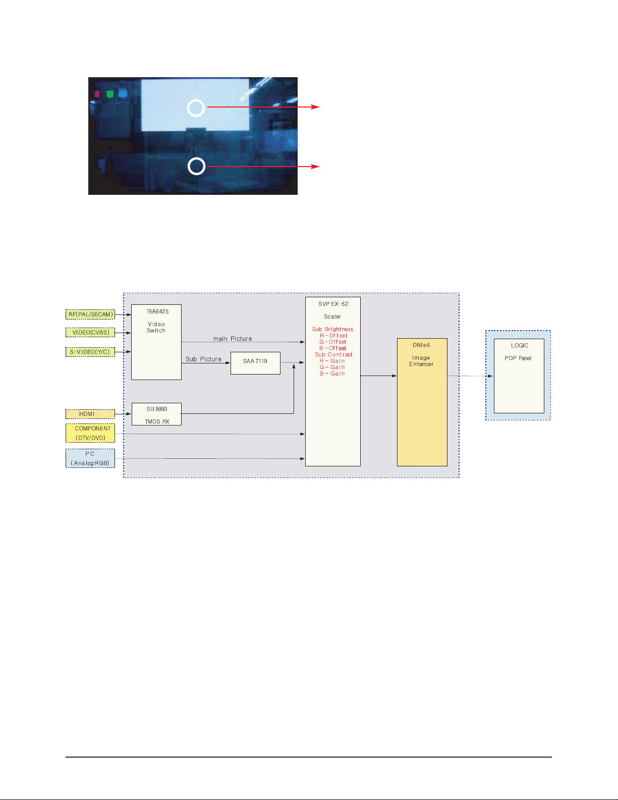
■ Chip Description
- SVP-EX62 : 480i/576i, CVBS, Y/C, HDMI, PC input Video signal processing
- SAA7119 : CVBS, Y/C Sub Video signal , Scart RGB signal processing
- DNIe-Lite : Image Enhancer
- Sii9993 : HDMI signal receiver
- MSP4410G : SIF, Analog Audio Decoder
- NSP6241A: Sound Output Control
- TAS5122 : Sound Amp
- M30620 : Main Micom
- 3F8668 : Sub Micom
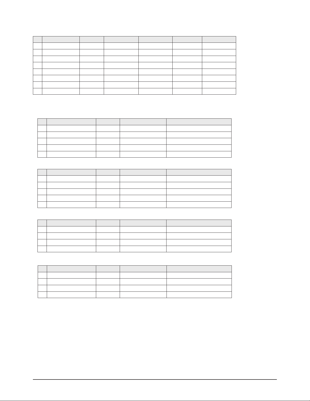
Block Specfication Major IC Remark
RF Tuner Alps TMQZ6-511A
Power
Input Voltage : AC 100V ~ 220V
Stand-By : 3W less
Video
Scaler SVP-EX62 (Trident)
Sub Decoder SAA7119 (Philips)
Picture Enhance DNIe-Lite (Samsung)
Video S/W TEA6425*2
Component S/W -
HDMI Sii9993 (Silicon Image)
Sound
Sound Processor MSP4410G (Micronas)
Sound Control NSP6241A
Audio S/W TEA6422*2
Sound Amp TAS5122
Sound Output 15W+15W
Control
CPU M30620 (Renesas)
Sub Micom 3F8668 (Samsung)
Remocon TM76
etc. Cabinet S5
Product Model PS-42P5H
Module V4 42" HD
Product Specification
2-2 Samsung Electronics
2-2 Key Features
Model PS-42P5H
Dimensions 1425.5 (W) x 114 (D) x 825.4 (H) mm
Weight 59.2 kg
Voltage AC 110 - 240V~ , 50 Hz
Power Consumption 290W
Number of Pixels 1024 (H) X 768 (V)
Screen Size 42 inches
VIDEO input
TV (VHF, UHF Antenna)
Scart1:CVBS/S-Video/RGB
Scart2:CVBS/S-Video
CVBS/S-Video
COMPONENT:480i/480p/720p/1080i
PC
HDMI
AUDIO input
Scart1
Scart2
COMPONENT
PC
HDMI
AV Output
VIDEO (CVBS)
AUDIO (L/R)
Audio Output
15W + 15W (8Ω)
■ H/W Configuration
- Video : SVP-EX62, TEA6425, BA7657F, DNIe-L
- Sound : MSP4440G, NSP6241A, TAS5122
- Tuner : TMQZ6-511A
■ S/W Configuration
- SVP-EX62 Trident Chip Control , DNIe-L
- CPU Master Control + Sub Micom, TTX Software
- Favorite CH, Label CH
■ Picture
- System : Video → PAL/SECAM/NTSC4.43,
Sound → Analog
- Progressive
- Output resolution : 1024*768
- OSD : Smart user Interface Grade1
- Picture Enhancement : DNIe-L
- Still picture, Noise reduction
- Comb Filter : 3D comb filter
- PIP : D/W, Large
- Panorama : Wide

Product Specification
Samsung Electronics 2-3
■ Sound
- System : Stereo
- Dolby Digital : Tru Surround XT
- Output : 15W + 15W
- Speaker : built-in.
■ Feature
- Component Interface(480i/480p/720p/1080i, Y/Pb/Pr)
- Digital Interface : HDMI
- Picture Size : Auto Wide/16:9/4:3/Panorama/14:9/Zoom/Wide 4:3
- Auto Program
- Sleep Timer : 180 minute
- Clock
- Zoom, Previous channel, White Screen, Color Tone
■ In/Out Terminals(Rear)
- 1 AV Input, 1 SVHS Input
- AV Monitor Output
- Component Input : 480i / 480p / 720p / 1080i
- 15 Pin D-sub Input : ~ XGA(1024 x 768)
- 1 HDMI Input (HDCP) : DTV(480p / 720p / 1080i)
- 1 RF Input
■ Remocon
- TM76
■ Power Supply
- 100V ~ 240V
■ Power
- Standy-by : 3W less
- Max Power : 380W
■ HDMI
- 640x480p @59.94/60Hz
- 720x480p @59.94/60Hz
- 720x576p @59.94/60Hz
- 1280x720p @59.94/60Hz/50Hz
- 1920x1080i @59.94/60Hz/50Hz
Product Specification
2-4 Samsung Electronics
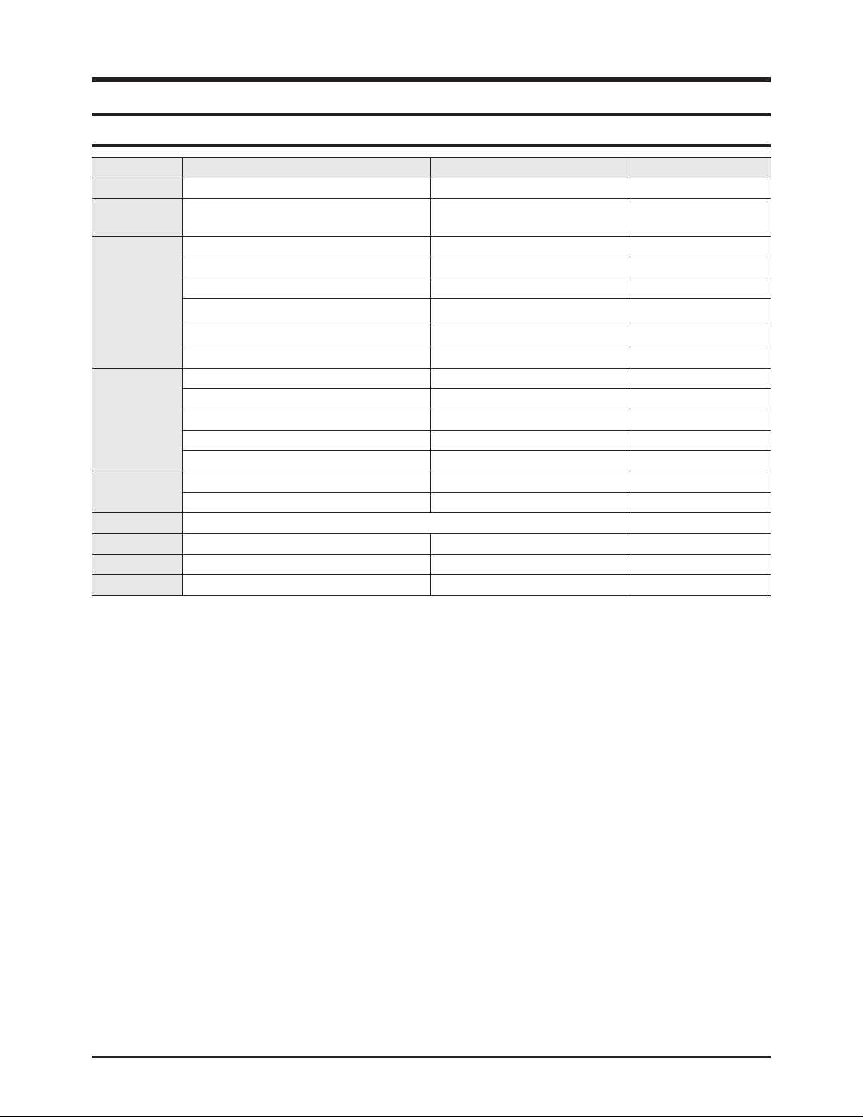
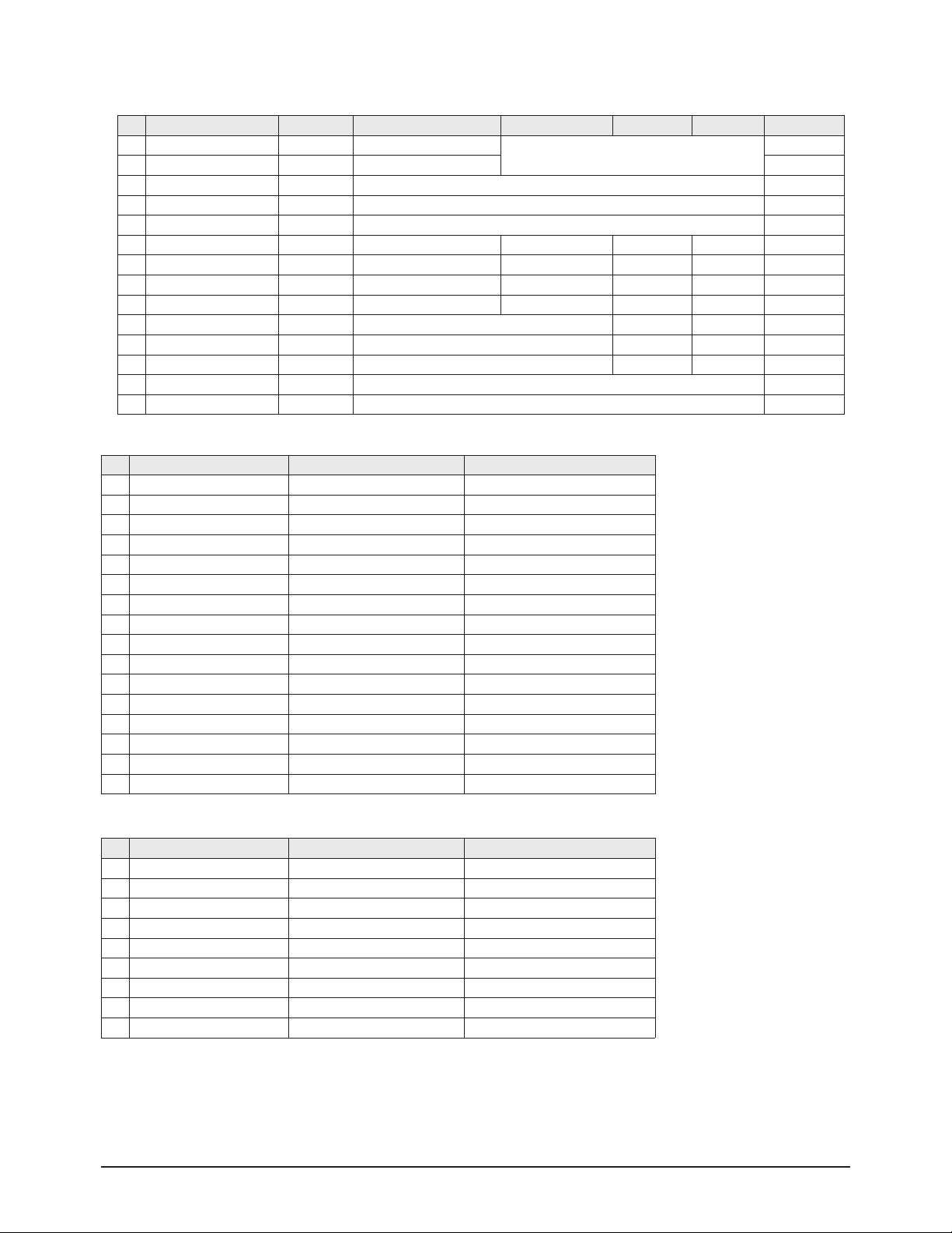
■ The table below shows all of the display modes that are supported. (N : Negative, P : Positive)
Resolution V-Freq.(Hz) H-Freq.(kHz)
Polarity
H V
IBM PC/AT
Compatible
640 X 350 70.086 31.469 N P IBM
720 X 400 70.087 31.469 P N IBM
640 X 480
59.94 31.469 N N VESADMT
70 35 N/P N/P VESAGTF
72.809 37.861 N N VESADMT
75 37.5 N N VESA DMT
800 X 600
56.25 35.156 N/P N/P VESADMT
60.317 37.879 P P VESADMT
70 43.75 N/P N/P VESAGTF
72.188 48.077 P P VESADMT
75 46.875 P P VESADMT
848 X 480
60 31.02 P P VESA DMT
74.769 37.684 N P VESA CVT
1024 X 768
60.004 48.363 N N VESADMT
70.069 56.476 N N VESA DMT
72 57.672 N/P N/P VESAGTF
75.029 60.023 P P VESA DMT
▶ The interlace mode is not supported.
▶ The television might operate abnormally if a non-standard video format is selected.
▶ 480i/p, 576i/p, 720p, or 1080i is not available in pc mode.

Product Specification
Samsung Electronics 2-5
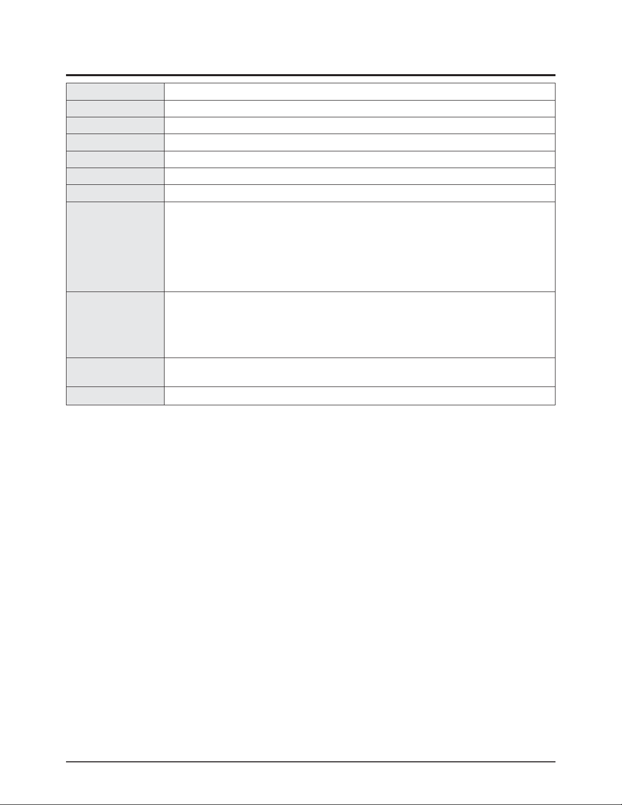
2-3 Specifications Analysis
Model Puccini(V4) Mozart (V3) Nelson (V3)
Design
Basic
Display Type PDP TV PDP TV PDP TV
Built-In Tuner O O O
Resolution
1024*768 852*480 852*480
PDP Module V4 V3 V3
Screen Size 42 inches 42 inches 42 inches
Aspect Ratio 16:09 16:09 16:09
Power Consumption 290W 330W 330W
Dimensions 1425.5 (W) x 114 (D) x 825.4 (H) mm 14255 (W) x 114 (D) x 825.4 (H) mm 14255 (W) x 114 (D) x 825.4 (H) mm
Weight 59.2 kg 59.2 kg 59.2 kg
Picture
Brightness 1300cd/m2 1000cd/m2 1000cd/m2
Contrast Ratio 10000:1 3000:01:00 3000:01:00
Image Enhacer DNIe-L DNIe 3 DNIe 3
Digital Comb Filter O O O
Audio
Equalizer O O O
Auto Volume O O O
Surround Sound SRS TreSurround XT SRS TreSurround XT SRS TreSurround XT
Speaker Output 15W +15W 15W +15W 15W +15W
Speaker Included Included Included
Features
PIP O O O
Double Screen O O O
Caption X X X
Still Image O O O
My Color Control O O O
Color Weakness O O O
Energy Saving O X X
Anynet X X X
D-Net(IEEE1394 S.400) X X X
POD X X X
Gemstar
(TV Guide On Screen)
X X X
Screen Burn Protection O O O
Connections
Antenna 1Input 1Input 1Input
CVBS 1AV 3AV 1AV
S-Video 1Input 2Input 1Input
Component(Y/PB/PR) 1Input 1Input 1Input
PC(D-SUB) 1Input(15Pin D-Sub) 1Input(15Pin D-Sub) 1Input(15Pin D-Sub)
DVI X O O
HDMI 1Input X X
Sub Woofer X X X
Optical X X X
Coaxial X X X

Product Specification
2-6 Samsung Electronics
2-4 Accessories
Accessories Item Item code Remark
SuppliedAccessories
User Manual BN68-00941F
Samsung Service center
Remote Control
AAABatteries
BN59-00468A
4301-000103
Power Cord 3903-000145
Accessories that can be purchased
additionally
S-VIDEO Cable -
Internal shopping mall
HDMI Cable -
HDMI/DVI cable -
Component Cables (RCA) -
PC Cable -
PC Audio Cable -
Scart Cable -
Antenna Cable -

Alignment & Adjustment
Samsung Electronics 3-1
3. Alignment & Adjustment
3-1 Service Instruction
* Check items listed after changing each
1. Main Board replace : ATM Channel fixing and White Balance adjustment
2. Main SMPS Board replace: Vs, Va Voltage check and adjust
5. DC-DC SMPS Board replace : Output voltage check and adjust
6. Logic Board replace : Not adjustment
7 : Y-Main Board replace : Not adjustment
8 : X-Main Board replace : Not adjustment
9 : Buffer Board replace : Not adjustment

Alignment & Adjustment
3-2 Samsung Electronics
3-2 How to Access Service Mode
■ Using the Customer Remote
1. Turn the power off and set to stand-by mode.
2. Press the remote buttons in this order; POWER OFF-MUTE-1-8-2- POWER ON to turn the set on.
3. The set turns on and enters service mode.
4. Press the Power button to exit and store data in memory.
※ If you fail to enter service mode, repeat steps 1 and 2 above.
5. Initial SERVICE MODE DISPLAY State
※ The firmware version is subject to change without notice.
4. Buttons operations within Service Mode
Factory AIR 10
White Balance
uPD64083
ADV7402 Main
SDP51
MST9883
ADV7402 Sub
DNIe
Logic
PW318
Option
PW318 Upgrade
TL945 Upgrade
Reset
Release Date : XXX XX XXXX XX:XX:XX
Code No. : M1 Micom XX
PW318 T_XXXXXXXXX-XXXX
TL945 0.XX
Current input mode
Firmware version
MENU Full Menu Display / Move to Parent Menu
Direction keys ▲ / ▼
Item Selection by Moving the Cursor
Direction keys ◀ / ▶
Data Increase/Decrease for the Selected Item
Source Cycles through the active input source that are connected to the unit
Alignment & Adjustment
Samsung Electronics 3-3
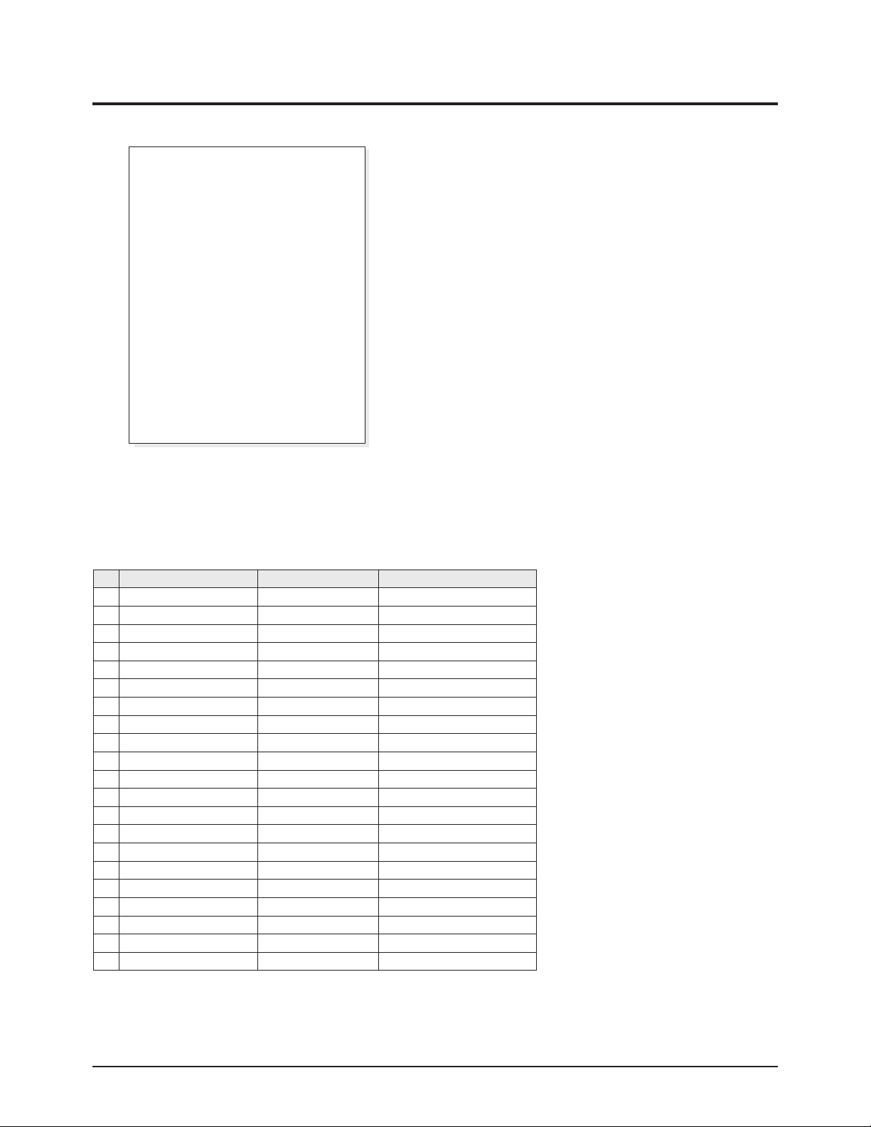
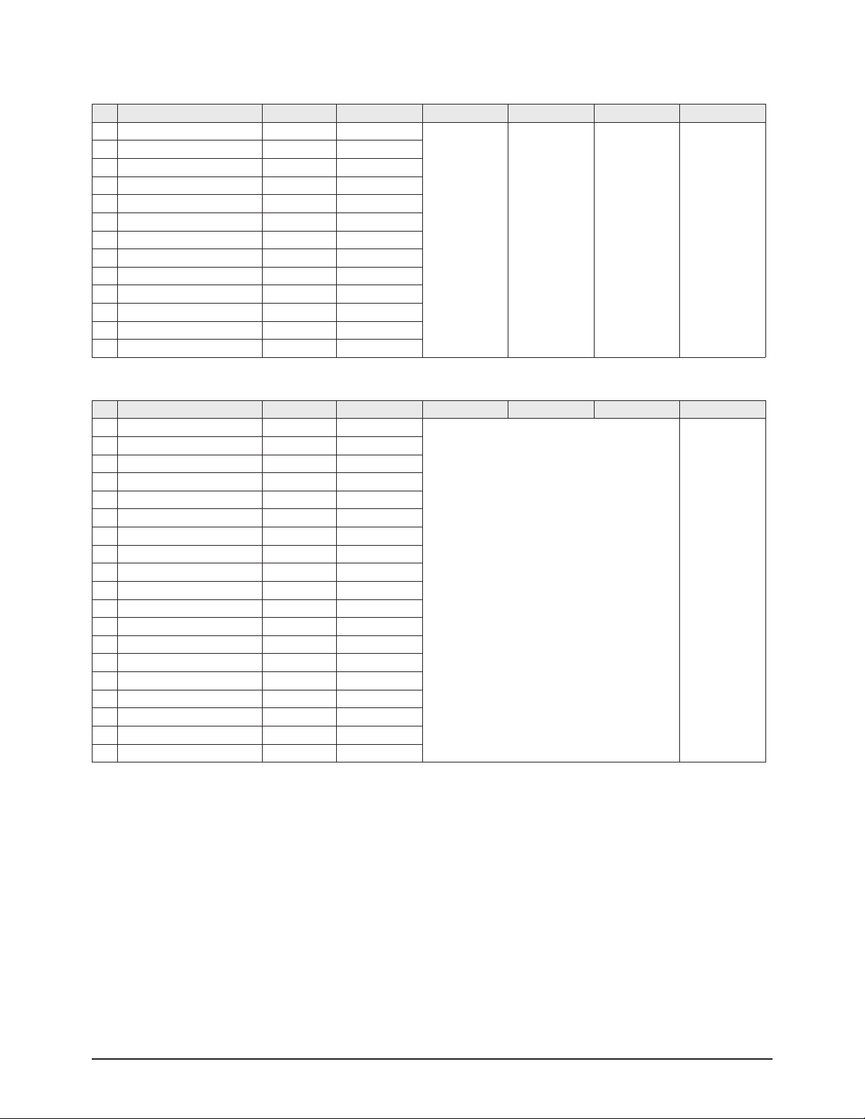
3-3 Factory Data
★ The underlined are items applied during the service adjustment. None of the others should be adjusted.
No ITEM Initial Value Remark
1 Panel Option 42S5S 42S5S/42D5S/42S5H
2 Gamma Mode - 2 Mode - 1,2,3,4
3 Analog Dimming Mode - 3 Mode - 1,2,3,4
4 Auto Power On ON/OFF
5 Key Lock OFF ON/OFF
6 Anynet OFF ON/OFF
7 DDC Write OFF ON/OFF
8 LNA ON ON/OFF
9 Ant. Gain Display OFF ON/OFF
10 Language English Osd language
11 Auto FM OFF ON/OFF
12 High Deviation Off ON/OFF
13 TTX On ON/OFF
14 TTX List Flop Flop/List
15 TTX TOP Off ON/OFF
16 TTX Group Auto Language TTX language
17 TTX Level Level 1.5 LEVEL 1.5 / 2.5
18 Shift Test OFF ON/OFF
19 Sound Delay1 OFF ON/OFF
20 Sound Delay2 OFF ON/OFF
21 Debug OFF ON/OFF
2. Option Table
1. Calibration
2. Option Table
3. White Balance
4. SVP-EX
5. SAA7119
6. MSP34XX/44XX
7. YC Delay
8. Adjust
9. DNIe
10. Chip Debugger OFF
11. Checksum
12. Reset
13. Spread Spectrum
14. Logic
T-PCN42PEUS-XXXX
SUB Micom Ver-xxxx
Fatory mode OSD Display
1. Calibration
① AV Calibration
② PC Calibration
③ DTV Calibration
Alignment & Adjustment
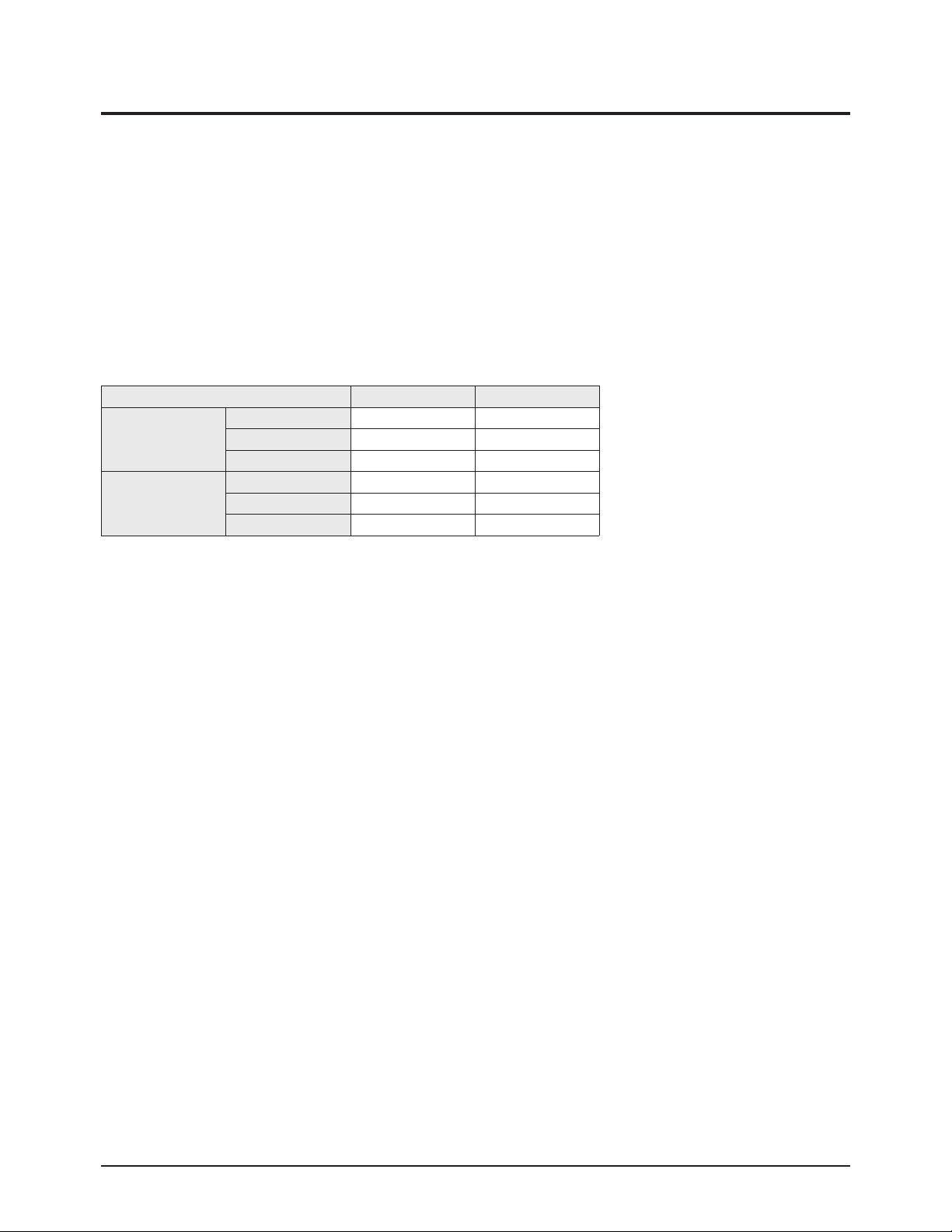
3-4 Samsung Electronics
No Item Range TV/AV Component PC DVI(HDMI)
1 Sub-Briteness 0~255 7 128 130 130
2 R-offset 0~255 138 128 138 138
3 G-offset 0~255 128 128 128 128
4 B-offset 0~255 146 128 144 144
5 Sub-Contrast 0~63 36 32 32 32
6 R-offset 0~255 128 128 128 128
7 G-offset 0~255 128 128 128 128
8 B-offset 0~255 148 128 128 128
3. White Balance
4. SVP-EX
No Item Range Initial Value Remark
1 Y-Filter 0 ~ 255 80H
2 0 ~ 255 80H
3 0 ~ 255 80H
4 0 ~ 255 80H
5 0 ~ 255 80H
①ComB Filter
②Peaking
No Item Range Initial Value Remark
1 V-Peaking 0 ~ 255 80H
2 Peaking Delay 0 ~ 255 80H
3 Peaking Gain 0 ~ 255 80H
4 Peaking Width 0 ~ 255 80H
5 Praking f0 0 ~ 255 80H
③NR
No Item Range Initial Value Remark
1 Y-NR-Off 0 ~ 255 80H
2 C-NR-Off 0 ~ 255 80H
3 Y-NR-ON 0 ~ 255 80H
4 C-NR-ON 0 ~ 255 80H
④Deinterlace
No Item Range Initial Value Remark
1 Motion 0 ~ 255 80H
2 80H
3 80H
4 80H
Alignment & Adjustment
Samsung Electronics 3-5
⑤Picture Gain Adjust
No Item Range TV/AV/S_Video Component PC DVI/HDMI
1 TCD3 Contrast 0 ~ 255 AV Calibration
78h
20h
2 TCD3 Brightness 0 ~ 255 AV Calibration
3 TCD3 CR Saturation 0 ~ 255 78h
4 TCD3 CB Saturation 0 ~ 255 78h
5 TCD3 YC Delay 0 ~ 15 00h
Range 480I/576I/480P/576P/1080I 720P PC HDMI
6 Analog Y/G offset 00 ~ 255 DTV Calibration PC Calibration 00 40h
7 Analog PB/B offset 00 ~ 255 DTV Calibration PC Calibration 02 00h
8 Analog PR/R offset 00 ~ 255 DTV Calibration PC Calibration 02 00h
9 Analog Y/G Gain 00 ~ 255 D6h E9h D6h
10 Analog PB/B Gain 00 ~ 255 FEh E9h FEh
11 Analog PR/R Gain 00 ~ 255 FEh E9h FEh
12 Black Level Setting 00 ~ 255 00h
13 Brightness(SVP) 0 ~ 255 00h
No Item Range Initial Value
1 HTC 00 ~ 255 2
2 ATVT 00 ~ 255 1
3 LUFI 00 ~ 255 5
4 NAICO_Brig 00 ~ 255 128
5 NAICO_Cont 00 ~ 255 64
6 NAICO_Satu 00 ~ 255 64
7 NAICO_Hue 00 ~ 255 3
8 COMP_Brig 00 ~ 255 162
9 COMP_Cont 00 ~ 255 92
10 COMP_Satu 00 ~ 255 64
11 TASKA_Brig 00 ~ 255 140
12 TASKA_Cont 00 ~ 255 64
13 TASKA_Satu 00 ~ 255 64
14 LIMOD 00 ~ 255 0
15 LIFIL 00 ~ 255 2
16 LIWGT 00 ~ 255 3
5. SAA7119
No Item Range Initial Value
1 FM-Prescale 00 ~ 255 20h
2 NT-M-Prescale 00 ~ 255 20h
3 SECAM-L-Prescale 00 ~ 255 22h
4 AV-Prescale 00 ~ 255 1Ah
5 I2S_1 Prescale 00 ~ 255 10h
6 I2S_2 Prescale 00 ~ 255 10h
7 Carrier Mute 00 ~ 255 42h
8 Pilot High 00 ~ 255 0Eh
9 Pilot Low 00 ~ 255 07h
6. MSP34XX/44XX
Alignment & Adjustment
3-6 Samsung Electronics
7. YC Delay
No Item Range TV/AV/S_Video Component PC DVI/HDMI Remark
1 RF PAL-B/G 00 ~ 255 102
77h 77h 77h
-
2 RF PAL-D/K 00 ~ 255 136
3 RF PAL- I 00 ~ 255 102
4 RF SECAM-B/G 00 ~ 255 51
5 RF SECAM-D/K 00 ~ 255 34
6 RF SECAM-L/L' 00 ~ 255 51
7 RF NTSC3.58 00 ~ 255 187
8 RF NTSC4.43 00 ~ 255 187
9 AV PAL 00 ~ 255 67
10 AV SECAM 00 ~ 255 34
11 AV NTSC 3.58 00 ~ 255 102
12 AV NTSC4.43 00 ~ 255 102
13 AV PAL60 00 ~ 255 119
8. Adjust
No Item Range TV/AV/S_Video Component PC DVI/HDMI Remark
1 Video Mute Time 10
-
2 Melody Volume 0 ~ 20 5
3 TTX Contrast 0 ~ 100 50
4 TTX Brightness 0 ~ 100 50
5 TTX Color 0 ~ 100 50
6 Dynamic Contrast 0 ~ 100 100
7 Dynamic Color 0 ~ 100 50
8 Dynamic Sharpness 0 ~ 100 60
9 Standard Contrast 0 ~ 100 90
10 Standard Brightness 0 ~ 100 80
11 Standard Color 0 ~ 100 70
12 Standard Sharpness 0 ~ 100 70
13 Movie Contrast 0 ~ 100 60
14 Movie Brightness 0 ~ 100 50
15 Movie Color 0 ~ 100 50
16 Movie Sharpness 0 ~ 100 40
17 RF_dB_1 0 ~ 255 0
18 RF_dB_2 0 ~ 255 0
19 RF_dB_3 0 ~ 255 0

Alignment & Adjustment
Samsung Electronics 3-7
9. DNIe Lite
No Item Range TV/AV/S_Video TV/AV/S_Video Component PC DVI/HDMI
1 PATT_SEL DNIe Lite 0x002C [13:08] 0 ~ 63 0
2 BLACK_TILT DNIe Lite 0x005E [15:08] 00 ~ 255 120 120 80 120
3 BLACK_GAINMAX DNIe Lite 0x00B9 [09:00] 00 ~ 1023 85 85 93 95
4 TEST_MCC DNIe Lite 0x00C1 [12] 0 ~ 1 0
5 OVERLAP_MCM DNIe Lite 0x00C1 [11:10] 00 ~ 03 0
6 AREA_EN_MCC DNIe Lite 0x0062 [15:11] 00 ~ 31 31
7 R-Offset(Post) DNIe Lite 0x0080 [09:00] -512 ~ 511 0 0 0 0
8 G-Offset(Post) DNIe Lite 0x0081 [09:00] -512 ~ 511 0 0 0 0
9 B-Offset(Post) DNIe Lite 0x0082 [09:00] -512 ~ 511 0 0 0 0
10 R-Gain(Post) DNIe Lite 0x007B [07 : 00] 0 ~ 255 128 128 128 128
11 G-Gain(Post) DNIe Lite 0x007C [15 : 08] 0 ~ 255 128 128 128 128
12 B-Gain(Post) DNIe Lite 0x007C [07 : 00] 0 ~ 255 128 128 128 128
13 Com_Offset_Sel(Post) DNIe Lite 0x00F2 [13] 0 , 1 1
14 Com_Gain_Sel(Post) DNIe Lite 0x00F2 [14] 0 , 1 1
10. Chip Debugger : ON/OFF
11. Checksum XXXX XXXX
12. Reset
13. Spread Spectrum
14. Logic
No Item Range Initial Value
1 Int/Ext Sel 0
2 Pat Sel 0
3 FCRL CON 0
4 Image Sticking 0
5 Error Mode Check 0
6 Error Code Table 0
7 Vs Reference 0
8 Vs Average 0
9 Vs to D/A 0
10 Va Reference 0
11 Va Average 0
12 Va to D/A 0
Alignment & Adjustment
3-8 Samsung Electronics
3-4 Service Adjustment
3-4-1 White Balance Adjustment
1. W/B Adjustment is required for the following two modes : : Component → Video
(Signal equipment : MSPG-925LTH, Measurement equipment : CA210)
※ To adjust HDMI, use the HDMI ↔ DVI conversion cable, and connect the DVI output from MSPG-925LTH to the HDMI input.
2. Adjustment Method
-Component and Video mode Adjustment PC, HDMI mode offset.
※ Thus, Micom saves the PS42S5S W/B data separately for each memory mode of the block
- White Balance Coordinates by Mode
VIDEO COMPONENT
H/L
(High Light)
x 265 265
y 265 265
Y(fL) 31 21
L/L
Low Light
x 280 280
y 285 285
Y(fL) 1.3 0.8
1. Pattern Generator Device: 925 LTH (Manufacturer: Master)
2. Adjust Pattern : ABL Pattern(Master 925LTH #16 Pattern)
3. Adjust Timing : Video - PAL(Master 925LTH Model #2)
Component - 720P(Master 925LTH Model # 6)
4. The adjustment procedures for each mode are described as follows:
1) Component
① Send the Toshiba ABLPattern (Pattern #16) of the 1080i (Model #5) resolution signal to theComponent in port using
the Master 925 LTH.
② Enter Factory mode, move to "White Balance" and click Select.
③ Set the coordinates of H/L and L/Lby adjusting "Sub Contrast", "Sub Bright", "R Drive", "G Drive", "B Drive", "R Cutoff"
, "G Cutoff" , and "B Cutoff".
2) Video
① Send the Toshiba ABLPattern (Pattern #16) of the 1080i (Model #5) resolution signal to the Video in port using the
Master 925 LTH.
② Enter Factory mode, move to "White Balance" and click Select.
③ Set the coordinates of H/L and L/Lby adjusting "Sub Contrast", "Sub Bright", "R Drive", "G Drive", "B Drive", "R Cutoff"
, "G Cutoff" , and "B Cutoff".
Alignment & Adjustment
Samsung Electronics 3-9
H/L Point
L/L Point

Alignment & Adjustment
3-10 Samsung Electronics
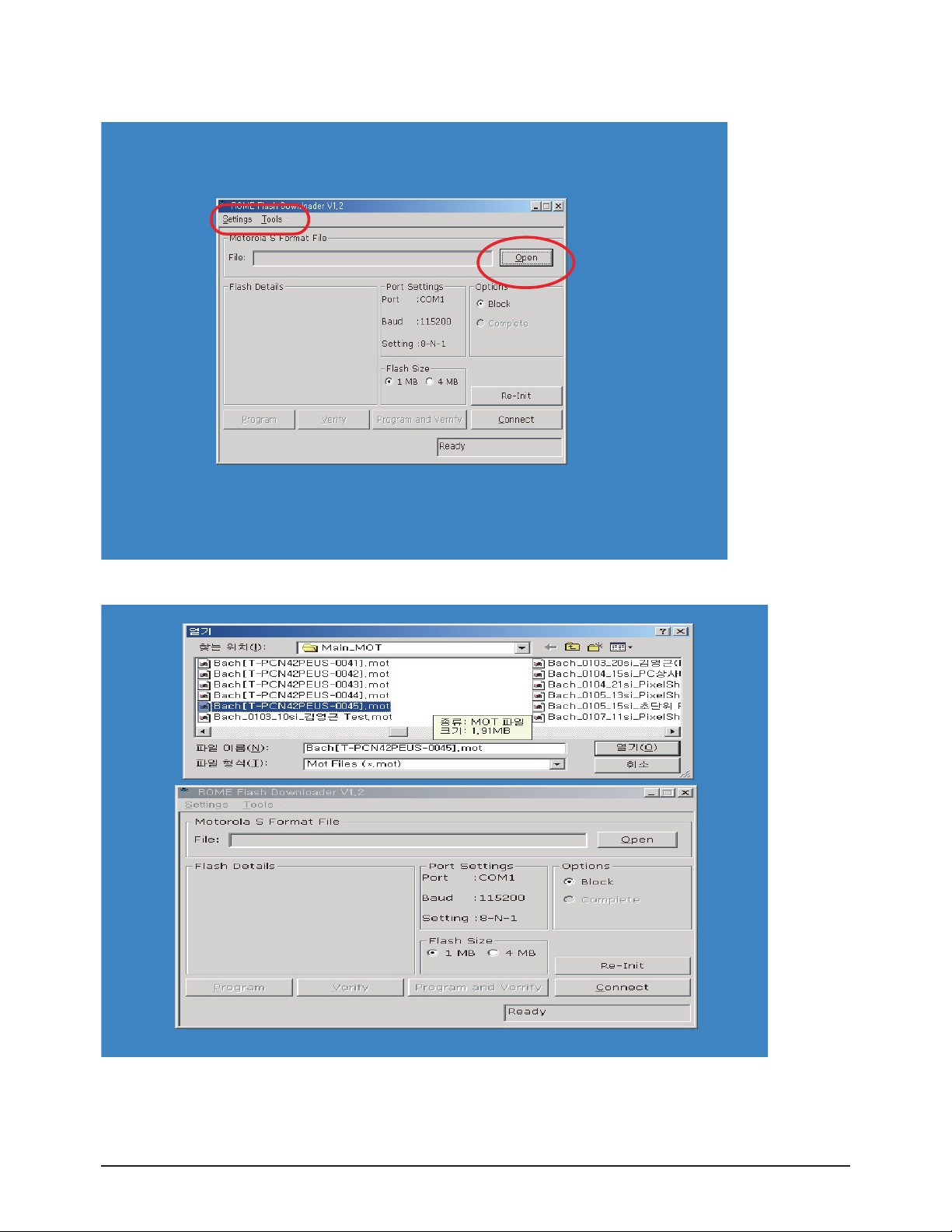
3-5 Software Upgrade
3-5-1 Digital Board TL945 Flash Upgrade
1. Connect one end of the RS-232C cable to the PC COM port and the other end of the cable to the PDP Service port while the
power of the PDP is off.
2. Rome Flash Downloader.
Alignment & Adjustment
Samsung Electronics 3-11
3. When the Flash Downloader is launched, click the Open button.
4. Select a file to be downloaded from the computer.
Alignment & Adjustment
3-12 Samsung Electronics
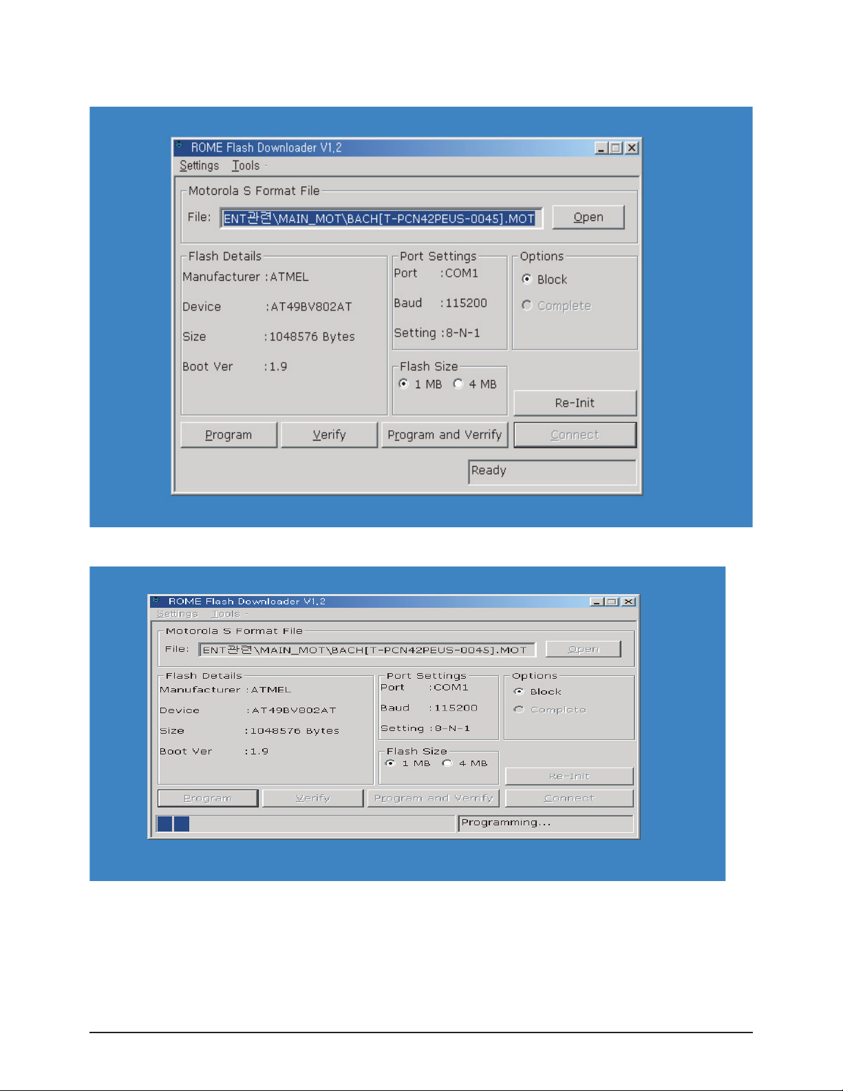
5. After selecting a target file, click the Connect button and turn the power on. When the program is activated, Ready click.
6. Note that the power must not be turned off during the download.
Alignment & Adjustment
Samsung Electronics 3-13
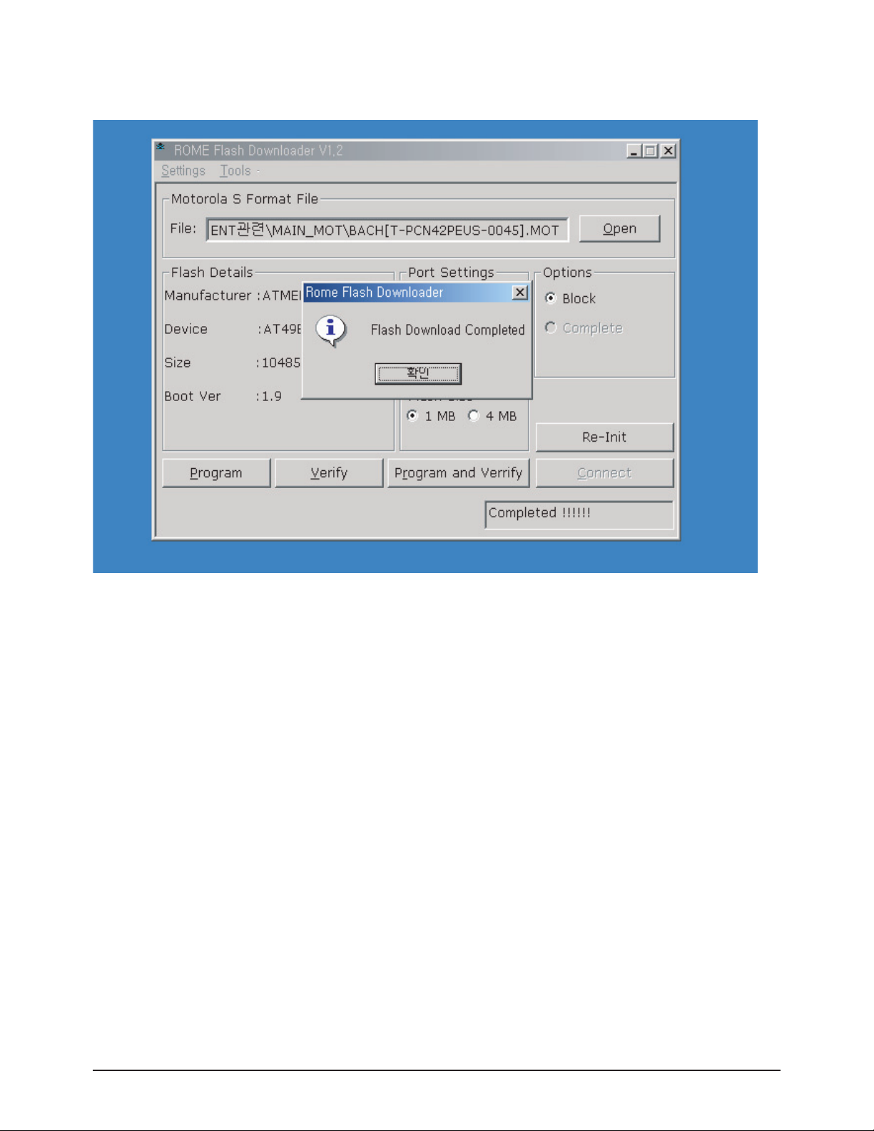
7. After the download is finished, the Flash Download Completed popup window opens. That indicates S/W upgrade is completed.
Alignment & Adjustment
3-14 Samsung Electronics
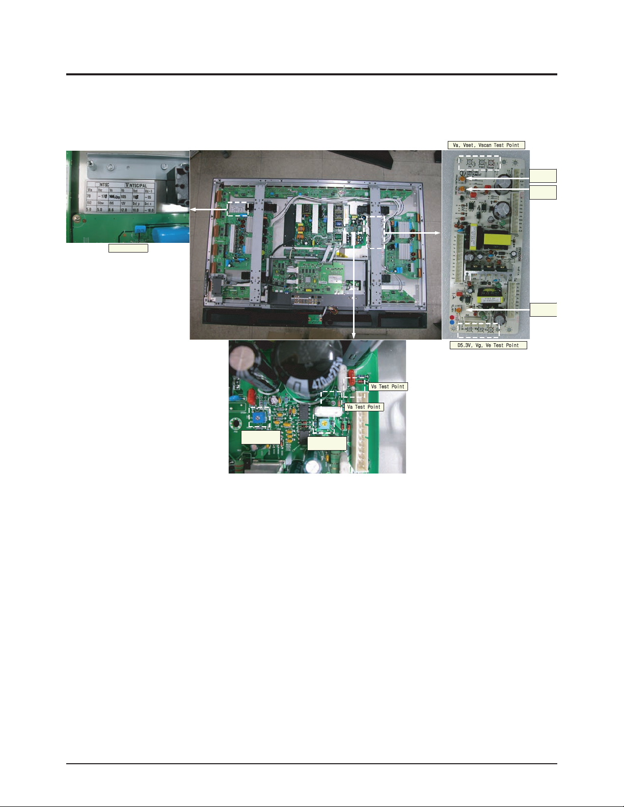
3-6 Replacements & Calibration
3-6-1 Voltage Adjustment
※ When the SMPS is replaced, the Va, Vs voltages must be checked and adjusted to the proper levels indicated on the panel
sticker.
adjustment
adjustment
Voltage Label
adjustment
Vscan
Vset
Ve
VR514 Va
adjustment
VR432 Vs
adjustment
4. Exploded View & Part List
Exploded View & Part List
Samsung Electronics 4-1
You can search for the updated part code through ITSELF web site.
URL:http://itself.sec.samsung.co.kr
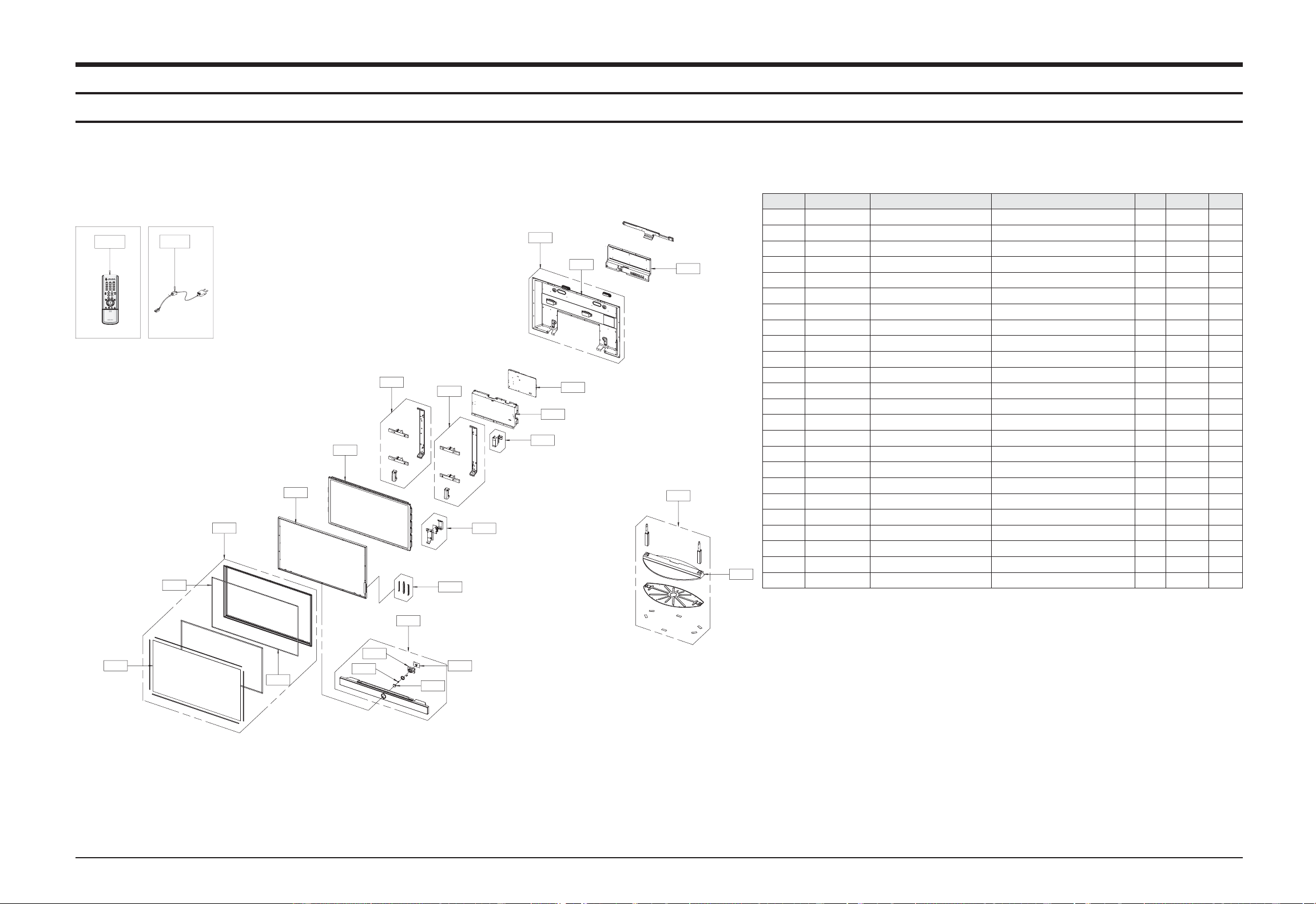
4-1 PS42P5HX/XEE
Loc.No. Code No. Description Specification Q'ty SA/SNA Remark
CIS7 AA61-60003B SPRING ETC-CS -,SUS304,-,-,OD11.2,N7,OD1 1 S.N.A
M0006 BN63-01633C COVER-REAR 42D5,S5,PCM,T0.5 1 S.N.A
M0006 BN63-01634C COVER-REAR SUB 42S5,SECC,T1.0 1 S.N.A
M0013 BN96-02140F ASSYSTAND P-BASE 42S5H,CIS,HIPS HB,BK07 1 S.A
M0013 BN96-01786C ASSYCOVER P-REAR 42D5,S5,PCM,T0.5 1 S.A
M0111 BN63-01813L COVER-STAND 42S5H,CIS,HIPS,T3.5,HB,BK07, 1 S.N.A
T0446 BN96-02704B ASSY BRACKET P-FRONT 42S5,42P5,EXPORT 1 S.N.A
M0145 BN96-02550A ASSY BOARD P-FUNCTION SCHUBERT,CT5000-36 1 S.A
M0146 BN96-02050B ASSY BOARD P-POWER & IR SCHUBERT,CT5000- 1 S.A
T0003 BN96-02693H ASSY COVER P-FRONT 42S5H,CIS,HIPS HB,BKN 1 S.A
T0023 BN64-00336A KNOB POWER 42P5,PC,VIOLET 1 S.N.A
T0044 BN96-01886A ASSY PDP MODULE P M1,SPD-42P5HD,D71A,V4, 1 S.A
T0073 AA63-01078A GASKET-EMI 42P5,AL POIL,T1.5,7,1006 2 S.N.A
T0073 AA63-01079A GASKET-EMI 42P5,ALPOIL,T1.5,W7,L614.5 2 S.N.A
T0074 BN59-00468A REMOCON PS42S5S,TM76A,59*22*209,ZILOG MB 1 S.A
T0079 BN94-00683C ASSY PCB MISC-MAIN PS-42S5H,PS-42P5H,D72 1 S.A
T0152 BN96-01774A ASSY BRACKET P-WALLRIGHT SPD-42P5HD,SEC 1 S.N.A
T0175 BN96-01737B ASSY SPEAKER P 8ohm,P5,42,15W,Urethan co 1 S.A
T0268 3903-000145 CBF-POWER CORD DT,EU,FP3/YES,U(IEC C13-R 1 S.A
T0275 BN96-02369A ASSY MISC P-INLET HP-R4252,STRAUSS,DOCUM 1 S.A
T0448 BN96-01775A ASSYBRACKET P-WALLLEFT SPD-42P5HD,SECC 1 S.N.A
T0456 BN67-00154A GLASS-FILTER EMI 42 P5,Mesh,44%,1053*639 1 S.N.A
T0555 BN96-01392R ASSY MISC P-BRKTTERMINAL 42S5,XEC,PCM T 1 S.N.A
T0603 BN64-00338A WINDOW-RMC 42P5,ACRYL,5% 1 S.N.A
T0074
T0268
T0044
T0003
T0446
T0073
T0152
T0448
M0145
T0091
M0013
M0006
T0275
M0006
T0079
T0555
M0013
M0111
T0175
T0603
T0456
T0073
CIS7
M0146
T0023
 Loading...