

Page 1

Owner's Handbook
Publication Part No. LRL0558ENX - 3rd Edition
© Land Rover 2003
All rights reserved. No part of this publication may be reproduced, stored in a retrieval system or transmitted in any form, electronic, mechanical,
recording or other means without prior written permission from Land Rover.
As part of Land Rover environmental policy, this publication is printed on paper made from chlorine free pulp.
Page 2

Owner’s Handbook
This handbook covers current Land Rover Defender models and, together with the Service
Portfolio book, provides all the information you need to derive maximum pleasure from owning
and driving your new vehicle.
For your convenience, the handbook is divided into sections, each dealing with a different
aspect of the vehicle. These are listed on the title page and you will find it worthwhile to take a
little time to read each one, and get to know your Defender as soon as you possibly can. The
more you understand before you drive, the greater the satisfaction once you are seated behind
the steering wheel.
* An asterisk appearing within the text identifies features or items of equipment that are either
optional, or are only fitted to some vehicles in the model range.
IMPORTANT
The specification of each vehicle will vary according to territorial requirements and also from
model to model within the vehicle range. Some of the information published in this handbook,
therefore, may not apply to your particular vehicle.
Land Rover operates a policy of constant product improvement and therefore reserves the right to change specifications
without notice at any time. Whilst every effort is made to ensure complete accuracy of the information in this handbook,
no liabilities for inaccuracies or the consequences thereof can be accepted by the manufacturer or the dealer, except in
respect of personal injury caused by the negligence of the manufacturer or the dealer.
2
Page 3

Contents
Quick Guide . . . . . . . . . . . . . . . . . . . . . . . .5
Introduction . . . . . . . . . . . . . . . . . . . . . . . .17
Controls & Instruments
Fascia Controls . . . . . . . . . . . . . . . . . . . . . 23
Locks & Alarm . . . . . . . . . . . . . . . . . . . . .24
Seats . . . . . . . . . . . . . . . . . . . . . . . . . . . . .33
Seat Belts . . . . . . . . . . . . . . . . . . . . . . . . .40
Child Restraints . . . . . . . . . . . . . . . . . . . .43
Door Mirrors . . . . . . . . . . . . . . . . . . . . . . .44
Instruments . . . . . . . . . . . . . . . . . . . . . . .45
Warning Lights . . . . . . . . . . . . . . . . . . . . .46
Lights & Indicators . . . . . . . . . . . . . . . . . .49
Wipers & Washers . . . . . . . . . . . . . . . . . .52
Horn . . . . . . . . . . . . . . . . . . . . . . . . . . . . .54
Manual Windows . . . . . . . . . . . . . . . . . . .55
Electric Windows . . . . . . . . . . . . . . . . . . .56
Sunroof . . . . . . . . . . . . . . . . . . . . . . . . . . .57
Heating & Ventilation . . . . . . . . . . . . . . . .58
Air Conditioning . . . . . . . . . . . . . . . . . . . .61
Heated Screens . . . . . . . . . . . . . . . . . . . . .63
Interior Equipment . . . . . . . . . . . . . . . . . .64
Exterior Equipment . . . . . . . . . . . . . . . . . .68
In-Car Entertainment . . . . . . . . . . . . . . . .69
Driving & Operating
Starting & Driving . . . . . . . . . . . . . . . . . . .73
Catalytic Converter . . . . . . . . . . . . . . . . . .78
Fuel Filling . . . . . . . . . . . . . . . . . . . . . . . .79
Manual Gearbox . . . . . . . . . . . . . . . . . . . .83
Transfer Gearbox . . . . . . . . . . . . . . . . . . .84
Brakes . . . . . . . . . . . . . . . . . . . . . . . . . . . .87
Traction Control . . . . . . . . . . . . . . . . . . . .90
Towing . . . . . . . . . . . . . . . . . . . . . . . . . . .91
Cab Pick-up . . . . . . . . . . . . . . . . . . . . . . .94
Load Carrying . . . . . . . . . . . . . . . . . . . . . .99
Ancillary Equipment . . . . . . . . . . . . . . . .100
Off-road Driving
Off-road Driving . . . . . . . . . . . . . . . . . . .105
Driving Techniques . . . . . . . . . . . . . . . . .109
Owner Maintenance
Maintenance . . . . . . . . . . . . . . . . . . . . . .117
Bonnet Opening . . . . . . . . . . . . . . . . . . .121
Engine Compartment . . . . . . . . . . . . . . .122
Engine Oil . . . . . . . . . . . . . . . . . . . . . . . .124
Cooling System . . . . . . . . . . . . . . . . . . . .125
Fuel System . . . . . . . . . . . . . . . . . . . . . .127
Brakes . . . . . . . . . . . . . . . . . . . . . . . . . . . 128
Clutch . . . . . . . . . . . . . . . . . . . . . . . . . . .129
Power Steering . . . . . . . . . . . . . . . . . . . .130
Washers . . . . . . . . . . . . . . . . . . . . . . . . .131
Wiper Blades . . . . . . . . . . . . . . . . . . . . . .133
Battery . . . . . . . . . . . . . . . . . . . . . . . . . .134
Tyres . . . . . . . . . . . . . . . . . . . . . . . . . . . .137
Cleaning & Vehicle Care . . . . . . . . . . . . .140
Identification Numbers . . . . . . . . . . . . . .143
Parts & Accessories . . . . . . . . . . . . . . . .144
Emergency Information
Wheel Changing . . . . . . . . . . . . . . . . . . .149
Emergency Starting . . . . . . . . . . . . . . . .157
Towing the Vehicle . . . . . . . . . . . . . . . . .159
Fuses . . . . . . . . . . . . . . . . . . . . . . . . . . .161
Bulb Replacement . . . . . . . . . . . . . . . . . .165
Technical Data
Lubricants & Fluids . . . . . . . . . . . . . . . . .171
Capacities . . . . . . . . . . . . . . . . . . . . . . . .173
Engines . . . . . . . . . . . . . . . . . . . . . . . . . .174
Electrical & Steering . . . . . . . . . . . . . . . .175
Wheels & Tyres . . . . . . . . . . . . . . . . . . .176
Dimensions . . . . . . . . . . . . . . . . . . . . . . .178
Weights . . . . . . . . . . . . . . . . . . . . . . . . .182
Fuel Consumption . . . . . . . . . . . . . . . . . .185
Appendices . . . . . . . . . . . . . . . . . . . . . . .186
Filling Station Guide
Filling Station Guide . . . . . . . . . . . . . . . .195
Page 4

Page 5

Quick Guide
Quick Guide
Quick Guide
GENERAL DATA
Recommended fuel
Diesel to EN 590.
Fuel tank capacity
90 Models: 60 litres
110 & 130 Models: 75 litres
WARNING
This vehicle is NOT compatible with
‘Bio-diesel’ fuel.
Tyre pressures - 90 Models
Front: 197 kPa
Rear: 262 kPa
Tyre pressures - 110 Models
Front: 197 kPa
Rear: 338 kPa
Tyre pressures - 130 Models
Front: 309 kPa
Rear: 457 kPa
For full technical data listings, please refer to
the ‘Technical Data’ section of this handbook,
see ‘LUBRICANTS AND FLUIDS’, page 171.
5
Page 6
CONTROLS
Quick Guide
5
6
H4959
4
12
39
6
LAND -
- ROVER
80
km/h
60
40
20
0
7
1. Fresh air vent control
2. Air blower control
3. Windscreen wiper/washer control
2
3
100
120
140
160
180
200
1
8
9
6. Air temperature & distribution controls
7. Air conditioning controls
*
8. Transfer gear lever
4. Lighting switch
9. Bonnet release lever
5. Direction indicators and horn control
NOTE: The precise specification and location of the controls may vary according to territorial
requirements and from model to model within the vehicle range.
NOTE: For further information on the controls, see ‘FASCIA CONTROLS’, page 23.
6
Page 7

FASCIA SWITCHES
Quick Guide
1 2 3 4 5 6
7
8
H4963
1. Rear fog guard lights*
Press to operate (see ‘FOG LIGHTS*’,
page 52)
2. Heated front screen
Press to operate (see ‘HEATED FRONT
SCREEN AND REAR WINDOW*’, page 64)
3. Heated rear screen*
Press to operate (see ‘HEATED FRONT
SCREEN AND REAR WINDOW*’, page 64)
4. Hazard warning lights
Press to operate (‘HAZARD WARNING
LIGHTS’, page 52)
5. Rear window wiper
Press to operate (see ‘REAR WINDOW
WIPER AND WASHER*’, page 54)
*
*
6. Rear window washer
Press to operate (see ‘REAR WINDOW
WIPER AND WASHER*’, page 54)
7. Electric windows
Press the appropriate switch to operate
the front left or right window (see
‘ELECTRIC WINDOWS *’, page 57)
8. Seat heaters
Press the appropriate switch to operate
the front left or right seat heater (see
‘HEATED FRONT SEATS*’, page 36)
*
*
*
7
8
7
Page 8
INSTRUMENT PANEL
Quick Guide
12
39
6
120
km/h
H4965
1. Speedometer
2. Anti-theft alarm indicator light
567
40
ABS
TC
5. Fuel gauge
NOTE: When the fuel remaining drops to a
1
100
80
km/h
60
20
0
3
4
2
120
140
160
180
200
minimum of 9 litres, the low fuel warning
3. Total distance (odometer) and trip
recorder
4. Trip recorder reset button
light will illuminate (see ‘WARNING
LIGHTS’, page 47).
6. Temperature gauge
7. Clock
NOTE: For further information on the instrument panel, see ‘INSTRUMENT PANEL’, page 45.
8
Page 9
WARNING LIGHTS
Quick Guide
4
ABS
TC
120
km/h
1 2 3
5 6
H4968
1. Low oil pressure (Red)
2. Battery charging (Red)
3. Handbrake (Red)
NOTE: If a warning light remains on or illuminates while driving, stop the vehicle and refer to the
relevant section of this handbook for advice.
NOTE: For further information on the warning lights, see ‘WARNING LIGHTS’, page 46.
4. Anti-lock braking system (Amber)*
5. Differential lock (Red)
6. Transmission oil temperature (Red)*
9
Page 10
Quick Guide
LIGHTS & INDICATORS
0
1
2
H3632
1. Side, tail and instrument panel lights
2. Headlights
Headlight main and dipped beams
3630
Push the lever away from the steering wheel to
change headlight beams.
To flash the headlights, pull the lever part way
towards the steering wheel and release.
Direction indicators
H3629
Move the lever DOWN to indicate a LEFT turn,
and UP to indicate a RIGHT turn.
NOTE: For further information concerning operation of the Lights and Indicators, please refer to
‘DIRECTION INDICATORS’, page 50 and ‘LIGHTS’, page 50.
10
Page 11
Quick Guide
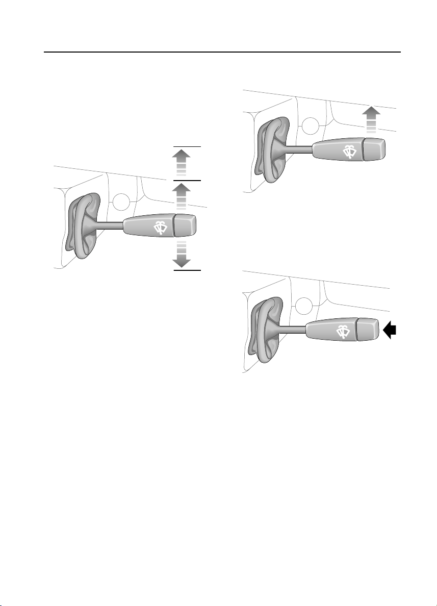
WIPERS & WASHERS
The wipers and washers will only operate when
the starter switch is turned to position ‘I’ or ‘II’.
WINDSCREEN WIPERS
3
2
H4969
1. Intermittent wipe
2. Normal speed wipe
3. Fast speed wipe
1
Single wipe
H3626
Push the lever up against spring pressure and
release immediately.
WINDSCREEN WASHER
H3628
Press to operate.
NOTE: For further information concerning operation of the wipers and washers, see ‘WINDSCREEN
WIPERS’, page 52 and ‘WINDSCREEN WASHER’, page 53.
11
Page 12
Quick Guide
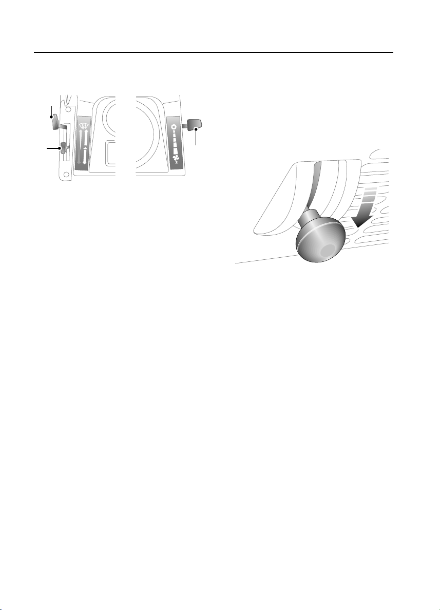
USING YOUR HEATER
3
2
H4970
Maximum heating
• Air blower control (1) - fully down.
• Air distribution control (2)- midway.
• Temperature control (3) - fully down.
Demisting and defrosting
• Air blower control (1) - fully down.
• Air distribution control (2) - fully up.
• Temperature control (3) - fully down.
NOTE: For further information concerning heater controls, see ‘HEATER CONTROLS’, page 59.
Maximum ventilation
• Air blower control (1) - fully down.
• Air distribution control (2) - fully down.
• Temperature control (3) - fully up.
Fresh air vents
1
H3719
To open a vent, pull the knob out and push the
levers downwards.
12
Page 13
Quick Guide
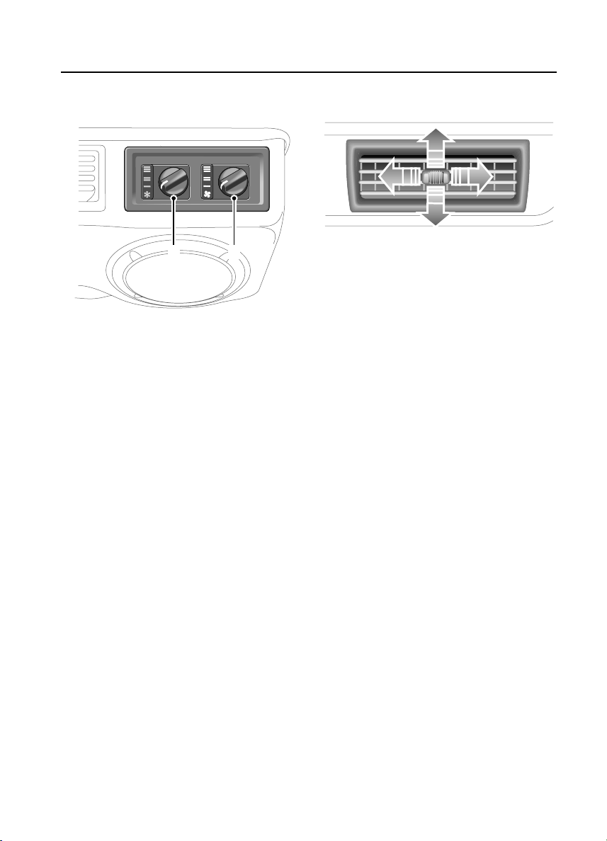
AIR CONDITIONING CONTROLS*
2
H3684
1. On/off blower control
2. Temperature control
NOTE: For further information concerning
heater controls, see ‘HEATER CONTROLS’,
page 59.
1
Air conditioning vents
H3756
The adjuster in the centre of each vent can be
used to adjust volume and direction of air. To
cut off the supply of air from any particular
vent, slide the adjuster fully to the left.
13
Page 14
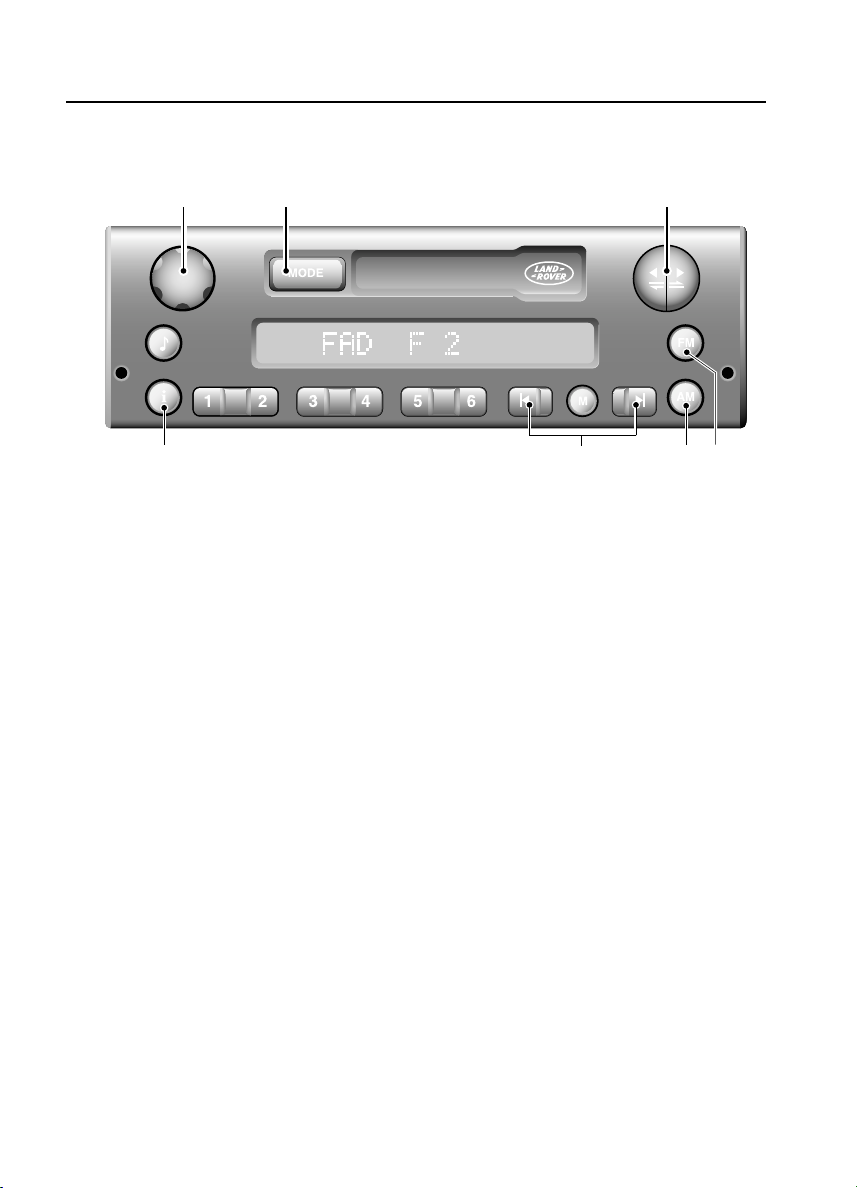
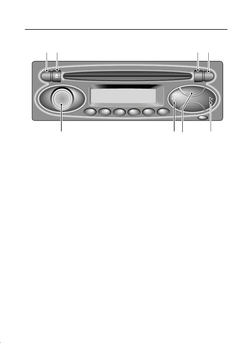
AUDIO SYSTEM CONTROLS
1 2 3
Quick Guide
7
H4986
1. On/off volume control
2. Mode selector (MODE)
3. Tape controls
4. FM selector
NOTE: For more information concerning the operation of your audio system, see your In-Car
Entertainment handbook.
5. AM selector
6. Scan buttons
7. Traffic and news information
6
5 4
14
Page 15
Quick Guide
162 3 4
RDS
FADE
BAL
BASS
TREB
1
2
34
6
5
CD
BAND
MENU
i
ICE1398
1. Radio Data System (RDS) selector
2. CD eject control
3. CD mode/repeat selector
4. Traffic and news information
5. Search controls
6. Waveband selector
7. Search controls
8. On/off and volume control
7 58
NOTE: For more information concerning the operation of your audio system, see your In-Car
Entertainment handbook.
NOTE: Some music CD manufacturers are using data encryption to 'copy-protect' their recordings
and prevent the production of pirate copies. These CDs differ from the internationally agreed CD
audio standard, RedBook, a standard that serves as the operating basis for all CD players and
changers.
Copy-protected CDs may not play in your Audio unit or CD changer or may be played subject to
various limitations, e.g., sound quality may be impaired.
If you do experience a problem, try the CD in other players before contacting the CD vendor.
15
Page 16

16
Page 17

Introduction
Introduction
WARNINGS IN THIS HANDBOOK
WARNING
Safety warnings are included in this
handbook. These indicate either a procedure
which must be followed precisely, or
information that should be considered with
great care in order to avoid the possibility of
personal injury or serious damage to the
vehicle.
BEFORE YOU DRIVE
WARNING
Your vehicle has a higher ground clearance
and, hence, a higher centre of gravity than
ordinary passenger cars. This will result in
different handling characteristics.
Inexperienced drivers should take additional
care, particularly in off-road driving
situations and when performing abrupt
manoeuvres on unstable surfaces.
SYMBOLS USED
The following symbols used within the
handbook call your attention to specific types of
information.
This recycling symbol identifies those
items that must be disposed of safely in
order to prevent unnecessary damage to the
environment.
*An asterisk appearing within the text,
identifies features or items of equipment that
are either optional, or are only fitted to some
vehicles in the model range.
SECURITY CARD
The security card, supplied with the literature
pack, contains important emergency
information. It is ESSENTIAL that you keep the
card safe from theft and ensure that it is passed
to the new owner if you sell the vehicle.
• Key number: This is the number of the
starter/door key - essential if you ever need
to obtain a replacement.
• Emergency key access code: You will need
this code in order to start the vehicle if the
handset has been lost or damaged (see
‘Emergency key access’, page 28).
• Locking wheel nut number: If your vehicle
has locking wheel nuts, you will have been
provided with a special wheel nut socket to
remove them. You will need to quote this
number to obtain a replacement socket.
• VIN (vehicle identification number): This
identity number is unique to your vehicle
and is essential proof of its specification.
The number can also be found in various
locations around the vehicle (see ‘VEHICLE
IDENTIFICATION NUMBER (VIN)’,
page 143).
• Radio security code number: This unique
code must be entered into the radio
whenever the power supply has been
disconnected. Without this code, the radio
unit will not operate (see 'Security code' in
the 'In-Car Entertainment' book).
WARNING
Never leave the security card inside the
vehicle when it is unattended.
Memorise the emergency key access code, or
keep the card on your person while driving, in
case of emergencies.
17
Page 18
Introduction
SERVICE PORTFOLIO
The Service Portfolio book included in your
literature pack contains important vehicle
identification information, details of your
entitlement under the terms of the Land Rover
warranty, as well as useful consumer advice.
Most important of all, however, is the section
on maintenance. This outlines the servicing
requirements for your vehicle and also includes
the service record slips, which the
Dealer/Authorised Repairer should sign and
stamp to certify that the routine services have
been carried out at the recommended intervals.
WARNING LABELS ATTACHED TO THE
VEHICLE
Warning labels attached to your vehicle
bearing this symbol mean: DO NOT
touch or adjust components until you
have read the relevant instructions in
the handbook.
Warning labels showing this symbol
indicate that the ignition system utilises
very high voltages. DO NOT touch any
ignition components while the starter
switch is turned on!
DIFFERENTIAL LOCK LABEL
THE DIFFERENTIAL LOCK SHOULD ONLY BE ENGAGED WHEN TRACTION IS LIKELY TO BE LOST.
WIDE THROTTLE OPENINGS SHOULD BE AVOIDED WHEN USED IN CONJUNCTION WITH
1st AND 2nd GEAR LOW RANGE. AS SOON AS THE DIFFICULT SURFACE HAS BEEN CROSSED THE
DIFFERENTIAL LOCK MUST BE RELEASED.
A SINGLE AXLE ROLLER RIG MAY BE USED FOR SPEEDS UP TO 5km/h. THE CENTRE
DIFFERENTIAL LOCK MUST BE DISENGAGED. FOR ROLLER TESTS OVER 5 km/H EITHER ALL FOUR
WHEELS MUST BE ROTATED AT THE SAME SPEED OR IF ONLY A SINGLE AXLE ROLLER RIG IS
AVAILABLE, THE CENTRE DIFFERENTIAL MUST BE LOCKED AND THE PROPELLER SHAFT TO
STATIONARY AXLE MUST BE REMOVED.
H3757
Information concerning operation of the
differential lock is printed on the centre
console. This is important information and
must be understood fully with reference to the
‘Gearbox and Transmission’ sections of this
handbook, before using the transfer gearbox.
The label contains the following warning:
“THE DIFFERENTIAL LOCK SHOULD ONLY BE
ENGAGED WHEN TRACTION IS LIKELY TO BE
LOST. WIDE THROTTLE OPENINGS SHOULD
BE AVOIDED WHEN USED IN CONJUNCTION
WITH 1st AND 2nd GEAR LOW RANGE. AS
SOON AS THE DIFFICULT SURFACE HAS BEEN
CROSSED THE DIFFERENTIAL LOCK MUST BE
RELEASED.
A SINGLE AXLE ROLLER RIG MAY BE USED
FOR SPEEDS UP TO 5 km/h. THE CENTRE
DIFFERENTIAL LOCK MUST BE DISENGAGED.
FOR ROLLER TESTS ABOVE 5 km/h EITHER
ALL FOUR WHEELS MUST BE ROTATED AT
THE SAME SPEED OR IF ONLY A SINGLE AXLE
ROLLER RIG IS AVAILABLE, THE
DIFFERENTIAL MUST BE LOCKED AND THE
PROPELLER SHAFT TO STATIONARY AXLE
MUST BE REMOVED.”
WARNING
18
Page 19
Introduction
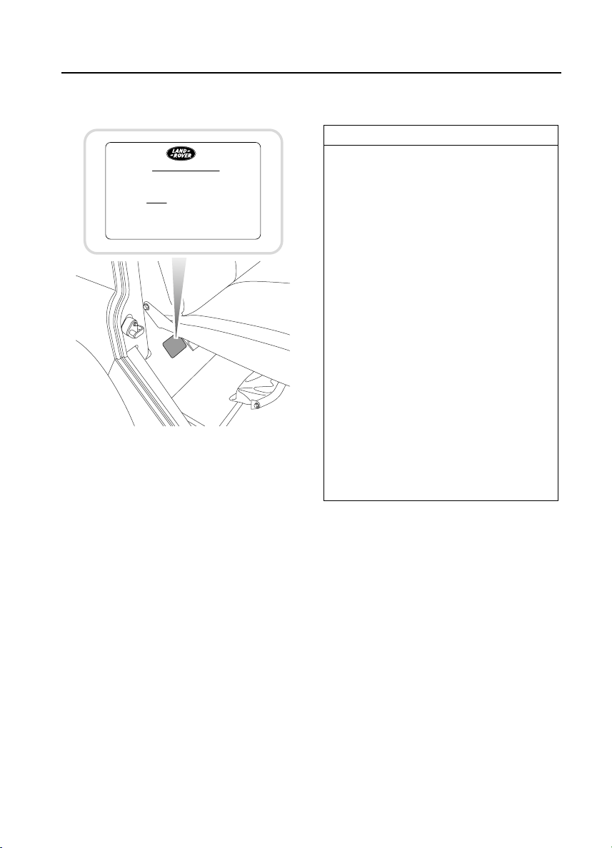
DIFFERENTIAL LOCK LABEL
IMPORTANT
BEFORE JACKING VEHICLE
1. ENGAGE DIFF. LOCK. (i.e. WARNING
LIGHT MUST BE ILLUMINATED
PRIOR TO SWITCHING OFF IGNITION.)
2. APPLY HANDBRAKE.
3. CHOCK WHEELS
H4730
Information concerning operation of the
differential lock when jacking up the vehicle is
given in the jack-stowage area. This is
important information and must be understood
fully with reference to the ‘Wheel Changing’
section of this handbook, before changing a
wheel. The label contains the following
warning:
IN AN EMERGENCY
IMPORTANT INFORMATION
Remember the breakdown safety code
If a breakdown occurs while travelling:
• Wherever possible, consistent with
road safety and traffic conditions, the
vehicle should be moved off the main
thoroughfare, preferably into a lay-by. If
a breakdown occurs on a motorway,
pull well over to the inside of the hard
shoulder.
• Switch on hazard lights.
• If possible, position a warning triangle
or a flashing amber light at an
appropriate distance from the vehicle to
warn other traffic of the breakdown,
(note the legal requirements of some
countries).
• Evacuate passengers through nearside
doors onto the verge, well away from
the road, as a precaution in case your
vehicle is accidentally struck by other
traffic.
“BEFORE JACKING VEHICLE:
1. ENGAGE DIFF. LOCK (i.e. WARNING
LIGHT MUST BE ILLUMINATED PRIOR TO
SWITCHING OFF IGNITION)
2. APPLY HANDBRAKE.
3. CHOCK WHEELS”
19
Page 20

20
Page 21

Controls & Instruments
Fascia Controls
FASCIA CONTROLS . . . . . . . . . . . . . . . . . . . . . . . 23
Locks & Alarm
KEYS AND HANDSETS. . . . . . . . . . . . . . . . . . . . . 24
ALARM SYSTEM . . . . . . . . . . . . . . . . . . . . . . . . . 24
INTERIOR SPACE PROTECTION . . . . . . . . . . . . . 27
ENGINE IMMOBILISATION . . . . . . . . . . . . . . . . . 28
REMOTE HANDSET BATTERY . . . . . . . . . . . . . . . 29
ALARM OR HANDSET DIFFICULTIES. . . . . . . . . . 31
CHILD-PROOF LOCKS . . . . . . . . . . . . . . . . . . . . . 32
TAIL DOORS . . . . . . . . . . . . . . . . . . . . . . . . . . . . 32
Seats
FRONT SEATS . . . . . . . . . . . . . . . . . . . . . . . . . . . 33
HEAD RESTRAINTS. . . . . . . . . . . . . . . . . . . . . . . 35
HEATED FRONT SEATS . . . . . . . . . . . . . . . . . . . . 35
FOLDING THE REAR SEATS. . . . . . . . . . . . . . . . . 36
Seat Belts
SEAT BELT SAFETY . . . . . . . . . . . . . . . . . . . . . . . 40
SEAT BELTS. . . . . . . . . . . . . . . . . . . . . . . . . . . . . 41
CARING FOR SEAT BELTS. . . . . . . . . . . . . . . . . . 42
Child Restraints
CHILD SEATS. . . . . . . . . . . . . . . . . . . . . . . . . . . . 43
Door Mirrors
EXTERIOR MIRRORS. . . . . . . . . . . . . . . . . . . . . . 44
Instruments
INSTRUMENT PANEL . . . . . . . . . . . . . . . . . . . . . 45
Warning Lights
WARNING LIGHTS. . . . . . . . . . . . . . . . . . . . . . . . 46
Lights & Indicators
DIRECTION INDICATORS. . . . . . . . . . . . . . . . . . . 49
LIGHTS . . . . . . . . . . . . . . . . . . . . . . . . . . . . . . . . 49
FOG LIGHTS. . . . . . . . . . . . . . . . . . . . . . . . . . . . . 51
HAZARD WARNING LIGHTS . . . . . . . . . . . . . . . . 51
Wipers & Washers
OPERATING. . . . . . . . . . . . . . . . . . . . . . . . . . . . . 52
WINDSCREEN WIPERS . . . . . . . . . . . . . . . . . . . . 52
WINDSCREEN WASHER . . . . . . . . . . . . . . . . . . . 53
REAR WINDOW WIPER AND WASHER . . . . . . . . 53
21
Page 22

Horn
HORN . . . . . . . . . . . . . . . . . . . . . . . . . . . . . . . . . 54
Manual Windows
FRONT AND REAR WINDOWS . . . . . . . . . . . . . . 55
SLIDING REAR WINDOWS. . . . . . . . . . . . . . . . . 55
Electric Windows
ELECTRIC WINDOWS. . . . . . . . . . . . . . . . . . . . . 56
Sunroof
SUNROOF . . . . . . . . . . . . . . . . . . . . . . . . . . . . . . 57
Heating & Ventilation
VENTILATION . . . . . . . . . . . . . . . . . . . . . . . . . . . 58
HEATER CONTROLS. . . . . . . . . . . . . . . . . . . . . . 59
USING YOUR HEATER . . . . . . . . . . . . . . . . . . . . 60
Air Conditioning
AIR CONDITIONING CONTROLS. . . . . . . . . . . . . 61
USING THE AIR CONDITIONING. . . . . . . . . . . . . 62
Heated Screens
HEATED FRONT SCREEN AND REAR WINDOW . 63
Interior Equipment
INTERIOR LIGHTS . . . . . . . . . . . . . . . . . . . . . . . 64
CLOCK . . . . . . . . . . . . . . . . . . . . . . . . . . . . . . . . 64
CIGAR LIGHTER . . . . . . . . . . . . . . . . . . . . . . . . . 65
ASHTRAY . . . . . . . . . . . . . . . . . . . . . . . . . . . . . . 65
CUBBY BOX* . . . . . . . . . . . . . . . . . . . . . . . . . . . 66
IN-CAR TELEPHONES. . . . . . . . . . . . . . . . . . . . . 66
INTERIOR REAR-VIEW MIRROR . . . . . . . . . . . . 67
LUGGAGE ANCHOR POINTS. . . . . . . . . . . . . . . . 67
Exterior Equipment
STEPS. . . . . . . . . . . . . . . . . . . . . . . . . . . . . . . . . 68
In-Car Entertainment
RADIO AERIAL . . . . . . . . . . . . . . . . . . . . . . . . . . 69
RADIO CASSETTE PLAYER. . . . . . . . . . . . . . . . . 69
22
Page 23
Controls & Instrum ents
Fascia Controls
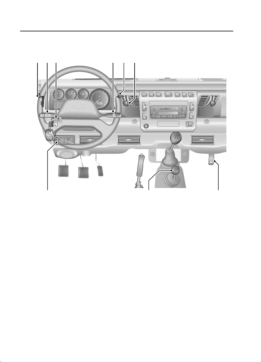
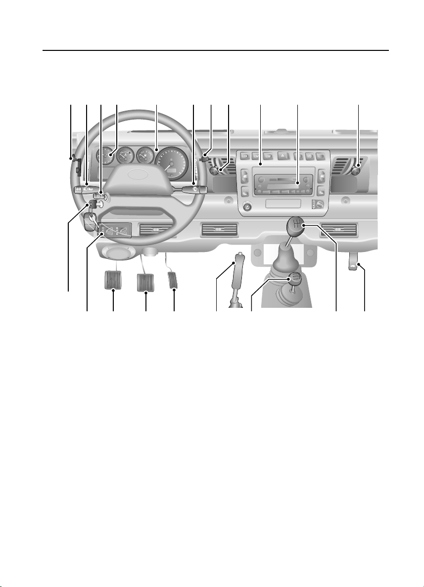
FASCIA CONTROLS
Fascia Controls
11
6
9
7
12
39
6
LAND -
- ROVER
8
100
80
km/h
60
40
20
0
16
14
15
12
H3748
1. Fresh air vent control
2. Audio system
3. Fascia switches (see overleaf)
4. Fresh air vent control
5. Air blower control
6. Direction indicators and horn control
7. Lighting switch
8. Instrument panel
9. Clock
10. Windscreen wiper/washer control
13
5
10
120
140
160
180
200
1
18
19
3
2
20
4
17
11. Air temperature & distribution controls
12. Air conditioning controls
*
13. Accelerator pedal
14. Brake pedal
15. Clutch pedal
16. Starter switch
17. Bonnet release lever
18. Handbrake
19. Transfer gear lever
20. Main gear lever
NOTE: The precise specification and location of the controls may vary according to territorial
requirements and from model to model within the vehicle range.
23
Page 24
Locks & Alarm
Locks & Alarm
KEYS AND HANDSETS
You have been supplied with two remote
handsets and two sets of keys, comprising:
• A black key for operating the starter switch
and door locks.
• A smaller metal key to operate the fuel filler
cap lock.
The starter key number is stamped on a tag
attached to the key ring. Check that the key
number has been entered in the space provided
on your Security card.
If the remote handset is lost, contact a Land
Rover Dealer/Authorised Repairer, who can
supply a replacement unit.
WARNING
Keep the Security card and spare handset and
keys in a safe place - NOT IN THE VEHICLE!
ALARM SYSTEM*
Your vehicle is fitted with a sophisticated
electronic anti-theft alarm and engine
immobilisation system. In order to ensure
maximum security and operating convenience,
you are strongly advised to gain a full
understanding of the alarm system, by
thoroughly reading this section of the
handbook.
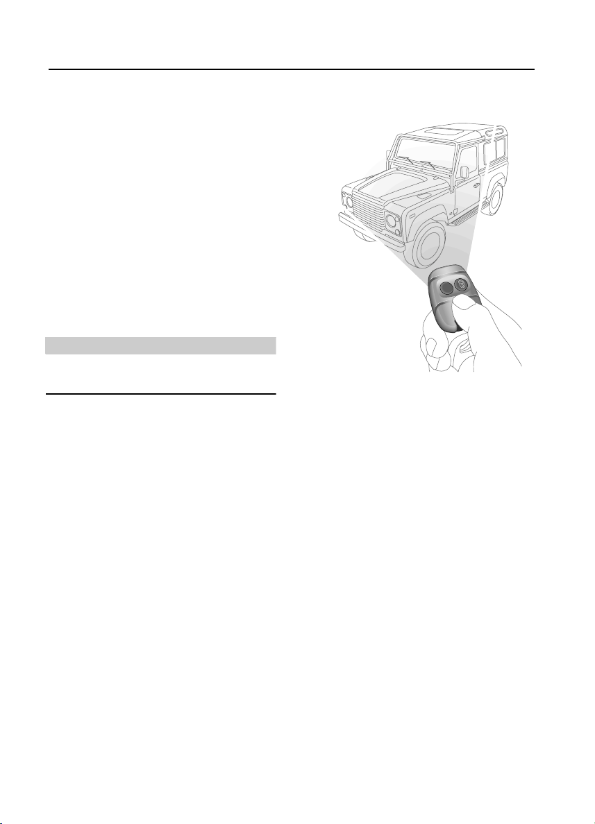
Using the remote handset
H3619
While it is not necessary to point the handset at
the vehicle, the handset must be within range of
the vehicle when a button is pressed. Note that
the operating range may vary depending upon
handset battery condition and may sometimes
be limited by physical and geographical factors
beyond your control. From a security point of
view, it may not be wise to unlock unless you
are within a few feet of the vehicle.
Vehicles with central door locking
Locking with the remote handset:
Press the lock (padlock symbol) button once:
• all doors are locked (including the tail door)
• engine immobilised
• perimetric alarm activated (protects the
doors and bonnet)
• interior space protection activated
*
The direction indicator lights flash three times
to confirm that the vehicle is secure and the
anti-theft alarm indicator light (in the
instrument panel) starts to flash.
24
Page 25
Locks & Alarm
Locking with the key:
Insert the key and turn the driver’s door lock
towards the rear of the vehicle:
• all doors locked (including the tail door)
• engine immobilised
• NO PERIMETRIC ALARM OR INTERIOR
SPACE PROTECTION
The anti-theft alarm indicator light (in the
instrument panel) starts to flash after 30
seconds to show that the engine is
immobilised.
Unlocking with the remote handset:
Press the unlock (PLAIN) button once to
disarm the alarm and unlock the doors.
The direction indicator lights flash once and the
interior lights illuminate.
Unlocking with the key:
While all the doors can be unlocked using the
key in the driver’s door lock, this method is NOT
RECOMMENDED - depending on the
specification of the vehicle the alarm may not
be disarmed.
Vehicles without central door locking
Locking & unlocking:
Each door lock must be operated individually,
using the key. The handset will NOT operate the
door locks. Turn the key towards the rear of the
vehicle to lock and towards the front to unlock.
Arming & disarming the alarm:
Press the lock button on the handset to arm the
alarm.
• Perimetric protection protects the doors
and bonnet.
• Interior space protection is activated.
• Engine is immobilised.
Provided the doors and bonnet are securely
closed, the direction indicators will flash three
times and the anti-theft alarm indicator in the
instrument panel will start to flash.
To disarm the alarm, press the unlock (PLAIN)
button on the handset; the direction indicators
will flash once and the interior lights illuminate.
Door sill locking buttons
From inside the vehicle, each door can be
individually locked by depressing the
appropriate sill locking button.
H3664
WARNING
DO NOT depress the sill buttons as a means of
locking the doors from outside the vehicle
(this practice - known as ‘slam locking’ - is
NOT recommended, because keys can be
locked inside accidentally).
On vehicles with central door locking, operation
of the driver’s door sill locking button locks all
the other doors too. However, engine
immobilisation and interior space protection
are suspended unless the handset lock button
is pressed as well.
25
Page 26
Locks & Alarm
20
40
60
80
100
120
140
160
180
200
2
NOTE: Slam locking, as described above, is
prohibited on vehicles with central door
locking.
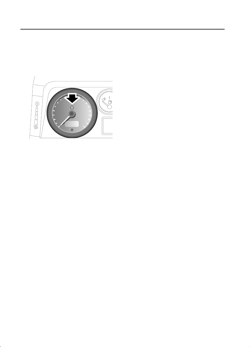
Anti-theft alarm indicator light
100
120
80
60
40
20
0
H3662
140
160
180
200
The indicator light in the speedometer (arrowed
in illustration) provides information about the
status of the alarm system, as follows:
When the alarm is armed:
The light flashes rapidly while the alarm is
arming itself. After ten seconds, the light
adjusts to a slower frequency and continues to
flash as an anti-theft deterrent until the alarm is
disarmed.
If the engine is immobilised (even though the
alarm has been disarmed):
The light flashes slowly until the engine is
remobilised.
If the alarm has been triggered:
The light will flash rapidly when the alarm is
disarmed until the starter switch is turned to
position II.
If the remote handset battery power is low:
The light will flash rapidly during the initial ten
seconds after the handset has been used, while
the alarm system is arming.
If the driver’s door is open:
The light illuminates for ten seconds, before
adjusting to slow frequency flashing.
Mislock
If a door is not fully closed when the handset
lock button is pressed, the hazard warning
lights will fail to flash, indicating a mislock. In
this case, the alarm system will not be fully
armed and on vehicles with central door
locking, none of the doors will lock.
As soon as the open aperture is closed, the
hazard warning lights will flash and the
anti-theft alarm indicator light will resume
flashing to confirm that the system has
returned to a fully armed state.
NOTE: If a mislock occurs as a result of an open
door, interior space protection will not be
activated.
NOTE: If a mislock occurs as a result of an open
bonnet, the door apertures will still be protected
by the alarm system and interior space
protection will be active.
If the alarm sounds
If the alarm is triggered, the alarm sounder or
vehicle horn will sound for 30 seconds before
switching off and resetting itself to the same
protection status that existed prior to the alarm
being triggered. The alarm can be triggered up
to three times before needing to be reset.
To silence the alarm, press either button on the
remote handset.
NOTE: While the alarm is sounding, the hazard
warning lights will flash to provide a visual
alarm.
26
Page 27
Locks & Alarm
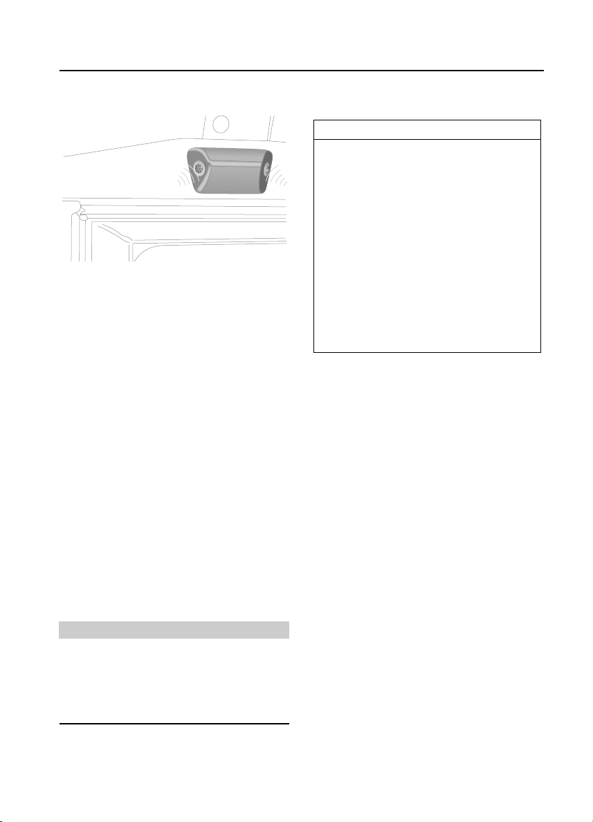
INTERIOR SPACE PROTECTION*
Interior space protection is designed to protect
the interior of the vehicle from intrusion (entry
by a thief through a smashed window, for
example). Twin sensors monitor the interior
space and activate the alarm if air movement is
detected in the passenger compartment.
Using the handset:
Interior space protection is activated
automatically whenever the remote handset is
used to set the alarm and can ONLY be
deactivated with the handset.
Key operation:
On vehicles fitted with central door locking,
using the key to arm the alarm will NOT activate
(or deactivate) interior space protection.
NOTE: Interior space protection cannot be
activated if a door is open, or if the starter
switch is turned on.
NOTE: Interior protection will not operate for
the first 15 seconds after the alarm is set.
Vehicles without central door locking
IMPORTANT INFORMATION
To disable interior space protection when
setting the alarm, use the following
procedure:
1. Open the driver’s door.
2. With the driver’s door open, use the
handset to arm the alarm in the
normal way.
3. Close the driver’s door (the hazard
warning lights flash three times and
the anti-theft indicator light
commences flashing rapidly).
The alarm system is now armed with
interior protection disabled.
WARNING
Never activate interior space protection if
windows or sunroof are to be left open, or if
passengers or animals are to be left inside
the vehicle - any movement will activate the
alarm.
27
Page 28
Locks & Alarm
ENGINE IMMOBILISATION
Engine immobilisation is an important aspect of
the security system, and includes a feature
known as ‘passive immobilisation’. This is
designed to safeguard the vehicle from theft,
should the driver forget to lock the doors or arm
the alarm. Engine immobilisation is automatic
whenever any of the following conditions
occur:
• The vehicle is locked using handset or key.
• Thirty seconds after the starter switch has
been turned off AND the driver's door
opened.
• Five minutes after the starter switch is
turned off, or the alarm system is disarmed.
IMPORTANT INFORMATION
The engine immobilisation system relies
on the handset to re-mobilise the engine.
Look after the handsets at all times,
protecting them from loss, damage and
battery discharge.
If the engine has immobilised passively,
re-mobilisation will occur when the starter
switch is turned to position ‘II’, provided
the handset is on the same ring as the key
and in close proximity to the switch.
• ALWAYS keep the handset on the same
ring as the key.
• NEVER attach both handsets to the
SAME key ring.
Any attempt to start the engine while it is
immobilised, will cause the engine
immobilisation warning light (in the
speedometer) to flash.
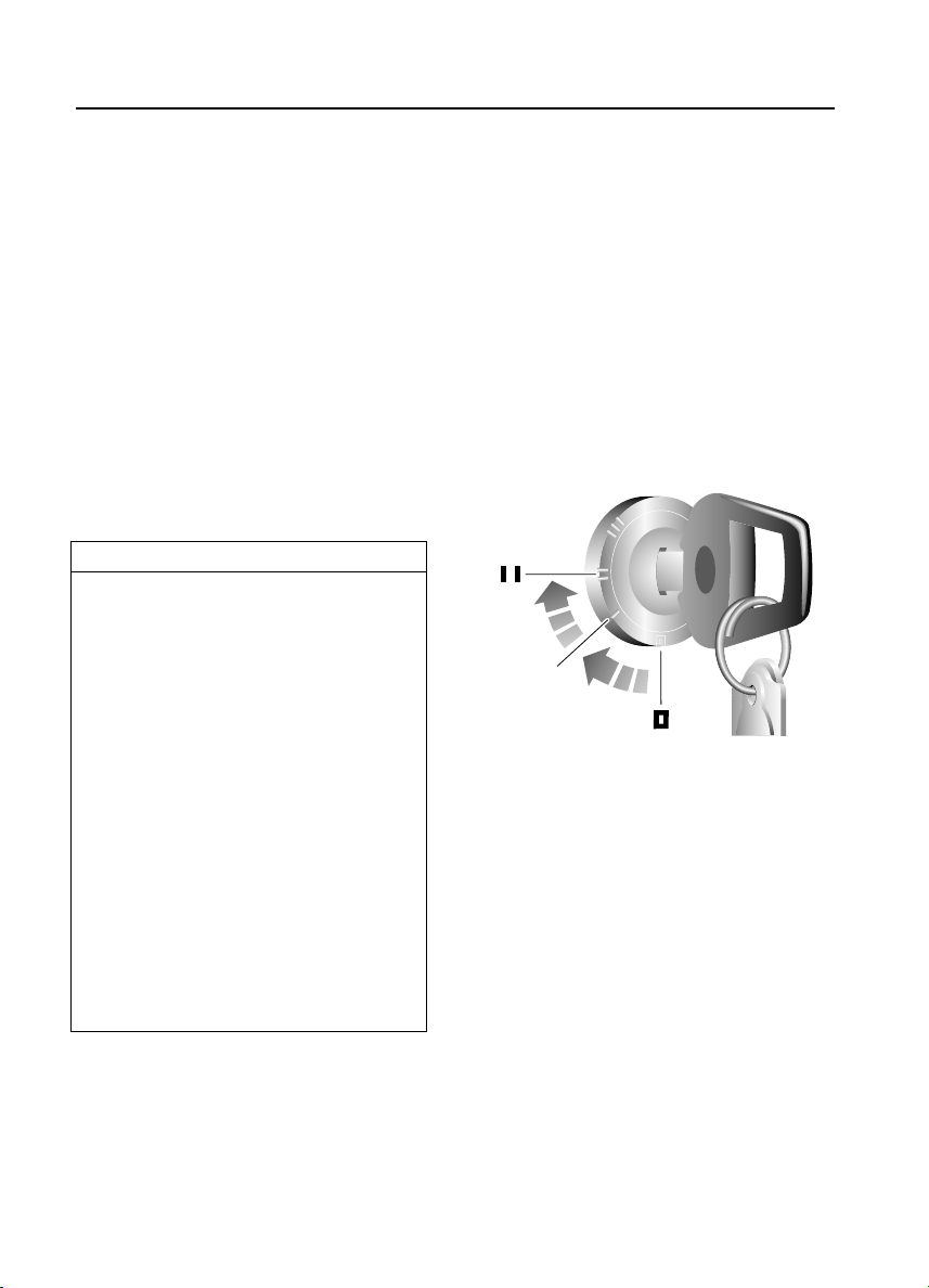
Emergency key access
If the handset is damaged, or fails to operate,
the engine can be re-mobilised by using the
starter key to enter a unique four number
emergency key access code. The code is
recorded on the Security card and is entered as
follows:
If your handset is lost or inoperative, it is
impossible to disarm the alarm. As soon as the
door is opened, the alarm will sound
(continuously for up to three 30 second
periods), and continue while the code is being
entered.
H3615
1. Remove the handset from the key ring and
keep the handset well away from the
starter switch when entering the code.
2. From inside the vehicle, with the driver’s
door closed, immediately insert the key
into the starter switch and turn to position
‘II’. Hold this position until the alarm
sounds, then switch off and open and
close the driver’s door.
3. Turn the starter switch to position ‘II’ the
required number of times to enter the first
digit of the code (if the first digit is 4, turn
the key to position ‘II’ and then back to ‘0’
four times).
4. Open and close the driver’s door (this will
enter the first digit of the code).
28
Page 29

Locks & Alarm
5. Turn the starter switch to position ‘II’ and
back to ‘0’ the required number of times to
enter the SECOND digit of the code.
6. Open and close the driver’s door again.
7. Turn the starter switch to position ‘II’ and
back to ‘0’ the required number of times to
enter the THIRD digit of the code.
8. Open and close the driver’s door again.
9. Turn the starter switch to position ‘II’ and
back to ‘0’ the required number of times to
enter the FOURTH digit of the code.
10. Finally, open and close the driver’s door
one more time.
If the code has been entered correctly, the
anti-theft indicator light will extinguish, the
alarm will stop sounding and the engine can be
started.
If an incorrect code has been entered:
If the code is entered incorrectly, the alarm
sounder will sound twice, the anti-theft
indicator light will continue to illuminate, and
the engine will fail to start. Before entering the
code again, turn the starter switch to position
‘II’ and hold in this position for 5 seconds.
After three failed entry attempts, the security
system invokes a delay period of thirty minutes
during which the system will not accept any
further attempts to enter a code.
REMOTE HANDSET BATTERY
The battery should last for approximately
three years dependent upon use. When the
battery needs replacing it will be apparent from
the following symptoms:
• The handset will only work every other
operation while disarming.
• The hazard warning lights will not flash
when the alarm is disarmed.
Always fit a Land Rover STC 4080 or a
Panasonic CR2032 replacement battery
(available from a Land Rover Dealer/Authorised
Repairer).
IMPORTANT INFORMATION
• DO NOT remove a battery until you are
ready to install the replacement.
• The engine will immobilise five minutes
after the key is removed from the
starter switch (or 30 seconds after the
starter has been switched off and the
driver’s door opened). If handset
battery replacement is NOT completed
within this period, the emergency key
access code will have to be entered
before the handset can be
synchronised.
IMPORTANT INFORMATION
Memorise the emergency key access code
or keep the Security card on your person in
case of emergencies. NEVER leave the card
in the vehicle.
WARNING
The handset contains delicate electronic
circuits and must be protected from impact
and water damage, high temperatures and
humidity, direct sunlight and the effects of
solvents, waxes and abrasive cleaners.
29
Page 30
Locks & Alarm
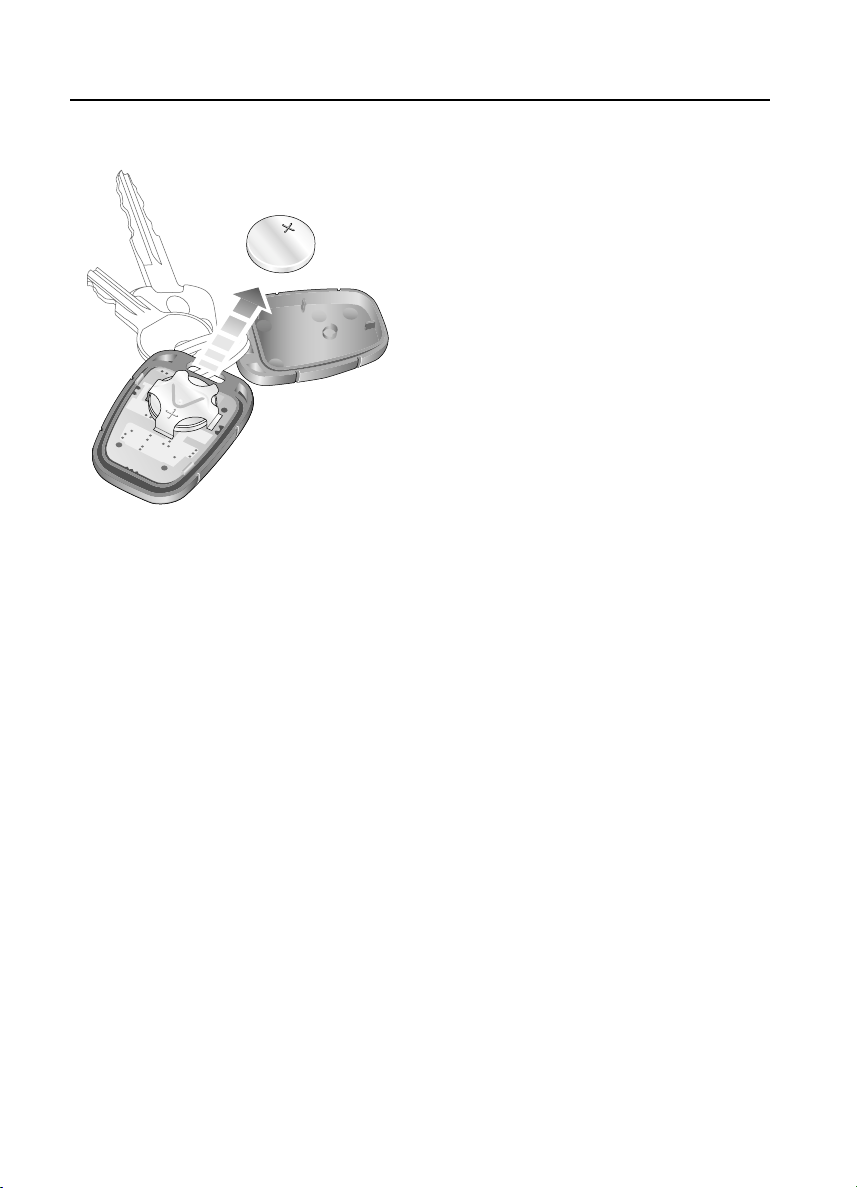
Battery replacement
H3663
1. Unlock the vehicle and disarm the alarm
system.
2. Turn the starter switch to position ‘II’, then
turn to position ‘0’ and remove the key.
3. Carefully prise the handset apart; start
from the key ring end using a coin or small
screwdriver. Avoid damaging the seal
between the two halves of the case and DO
NOT allow dirt or moisture to get inside
the handset.
4. Slide the battery out of its clip, taking care
to avoid touching the circuit board or the
contact surfaces of the clip.
5. Press and hold one of the buttons for at
least five seconds (this will drain any
residual power from the handset).
6. Fit the new battery, ensuring that correct
polarity is maintained (‘+’ side facing up).
Finger marks will adversely affect battery
life; if possible, avoid touching the flat
surfaces of the battery and wipe them
clean before fitting.
7. Press the two halves of the handset firmly
together and ensure that both halves are
fully joined, to prevent dirt or moisture
from entering the handset.
8. Operate the PADLOCK symbol button at
least four times within range of the vehicle
to resynchronise the handset.
9. Press the unlock button once to unlock the
vehicle.
The handset is now ready for use.
30
Page 31

Locks & Alarm
ALARM OR HANDSET DIFFICULTIES
If the alarm goes off unexpectedly:
Ensure all the windows and sunroof are closed,
or if they need to be left open, disable interior
space protection.
If the alarm goes off when a door is opened:
Disarm the alarm with the handset before
unlocking. If the handset has failed, enter the
emergency key access code (refer to
‘Emergency key access’, page 28).
If the starter will not operate:
Ensure the handset is on the same key ring as
the starter key. If it still will not operate, consult
a Land Rover Dealer/Authorised Repairer.
If the hazard warning lights fail to flash when
the alarm is armed:
A door or bonnet is partially opened - close the
open aperture and try again.
IMPORTANT INFORMATION
Battery disconnection
Your vehicle is equipped with a battery
backed-up sounder
an anti-theft siren if the vehicle battery is
disconnected.
Before disconnecting the vehicle battery, it
is ESSENTIAL to refer to ‘Battery removal
and replacement’, page 135, in order to
prevent the alarm from sounding.
If the vehicle battery is disconnected for
any reason, the status of the security
system prior to disconnection will be
memorised and automatically reset when
the battery is reconnected.
*, which operates as
31
Page 32

Locks & Alarm
CHILD-PROOF LOCKS*
H3661
Move the locking levers on the rear doors down
to engage the child locks.
With the child-proof locks engaged, the rear
doors cannot be opened from inside the
vehicle, thereby avoiding the risk of a door
being opened accidentally while the vehicle is
moving.
WARNING
NEVER leave children unsupervised in the
vehicle.
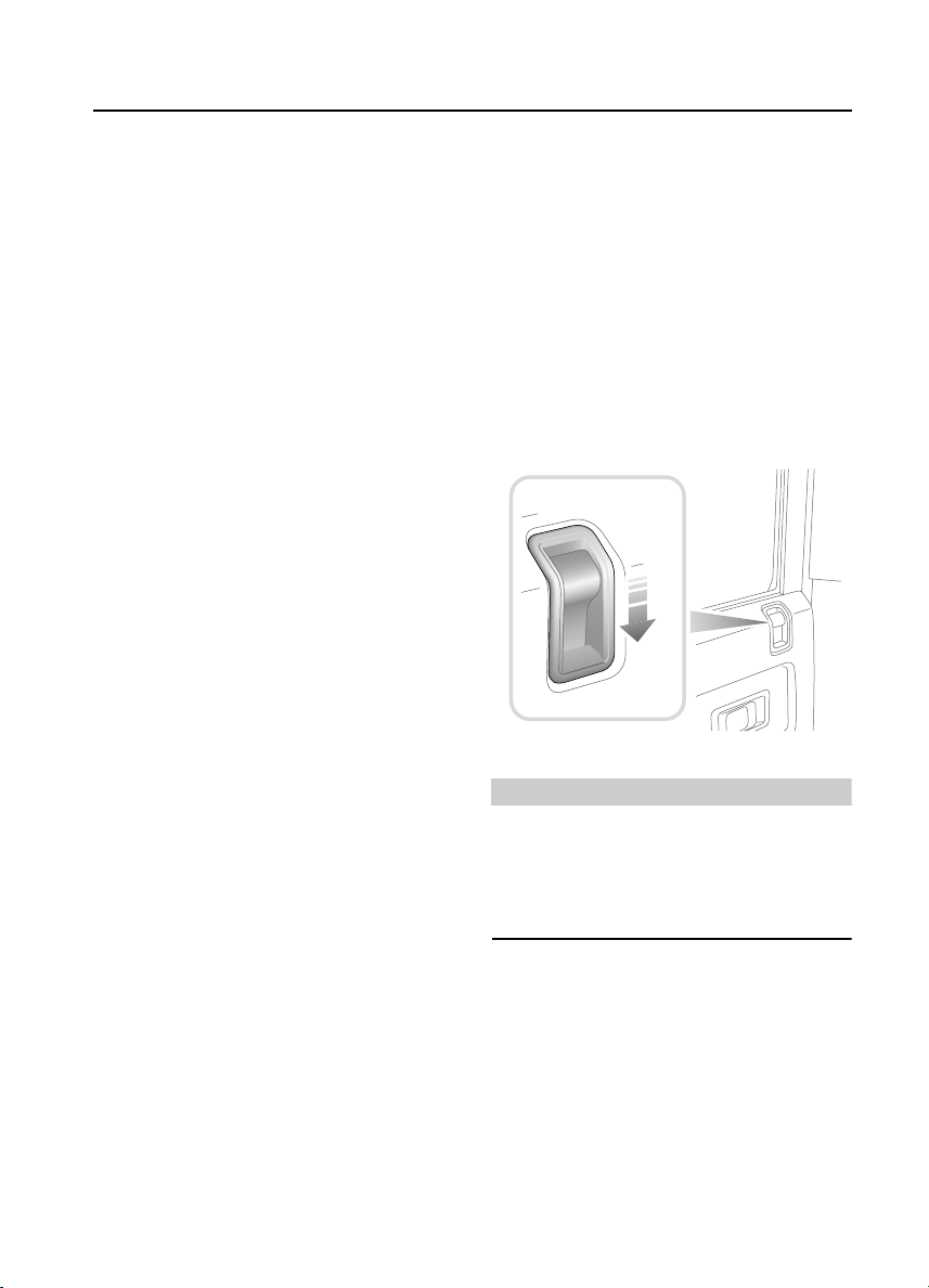
TAIL DOORS*
H3618
From outside, use the key to lock and unlock
the taildoor. From inside and with the door
closed, push the locking button up to lock and
down to unlock (see illustration).
32
Page 33

Seats
Seats
FRONT SEATS
WARNING
To avoid the risk of loss of control and
personal injury, DO NOT adjust the driver's
seat or head restraint while the vehicle is in
motion.
Sitting correctly
The seats, head restraints and seat belts all
contribute to the protection of the occupants.
Optimal use of these components will give you
more protection. Therefore, observe the
following points:
• Sit in the most upright position with the
base of your spine as far back as possible
and the backrest not reclined more than
30 degrees.
• Adjust the head restraints so that the top of
the head restraint is level with the upper
portion of the head.
• Do not move the front seat too close to the
instrument panel. The driver should hold the
steering wheel with slightly bent arms. The
legs should also be slightly bent so that the
pedals can be pressed to the floor.
• The seat belt should rest in the centre of the
shoulder. The lap part should fit tightly
across the hips and not on the stomach.
o
max. 30
H4721
Forward/backward adjustment
H3708
Lift the bar at the front of the seat to slide the
seat forward or back. Ensure the seat is locked
in position before driving.
33
Page 34

Seats
Seat back adjustment
H3707
Lift the lever on the side of the seat and lean
backwards or forwards to achieve the desired
angle, then lower the lever to lock.
WARNING
DO NOT travel with the seat backs reclined
steeply rearwards. Optimum benefit is
obtained from the seat belt with the seat back
angle set to approximately 30 degrees from
the upright (vertical).
Seat cushion removal
H3709
WARNING
ENSURE that the seat cushion is securely in
place before driving.
The front seat cushions can be removed to
access the battery and secondary fuse box as
follows:
Pull up the front of the seat base to release it
from its retaining clips, then pull the cushion
forward to remove.
34
Page 35

Seats
When replacing, insert the lugs at the back of
the seat cushion into the corresponding holes
where the seat base meets the seat back, then
push firmly down on the front of the seat
cushion to secure in place.
NOTE: On cars equipped with seat heaters, an
electrical lead connects the heater unit in the
seat cushion with the vehicle wiring harness.
When removing the seat cushion care must be
taken to avoid straining or damaging the lead.
HEAD RESTRAINTS
H3710
Pull the head restraint up or down until the
cushion is level with the back of the head.
WARNING
Head restraints are designed to support the
back of the head (NOT THE NECK), and to
restrain rearward movement of the head in
the event of a collision. The restraint must be
positioned level with the head to be effective.
HEATED FRONT SEATS*
H3670
With the starter switch turned on, press the
switches to operate the heating elements in
either the driver's or front passenger seat (the
indicator light in the switch illuminates). Press
a second time to switch off.
The seat heaters are thermostatically controlled
and operate intermittently to achieve and then
maintain a predetermined temperature between
26° - 36°C.
IMPORTANT INFORMATION
The seat heaters consume considerable
power from the battery. For this reason,
they should ONLY be operated while the
engine is running.
NOTE: The centre front seat
with heating elements.
* is not equipped
35
Page 36

Seats
FOLDING THE REAR SEATS
WARNING
DO NOT adjust the seats while the vehicle is
in motion.
When re-erecting the 60/40 split rear seats
ensure that the seat stands are properly
positioned.
When the seat is erected, the latching
mechanism should be visually checked and
physically tested to ensure that the latch is
secure before driving.
Before folding the rear seats:
• Slide the front seats forward.
• Ensure that the outer rear seat belts are
correctly stowed.
• Pass the seat belt locks through the junction
of the backrest and the cushion and into the
loadspace.
NOTE: When unfolding the rear seats, the seat
belt locks must be passed back through the
junction of the backrest and the cushion.
*,
60/40 split rear seats*
1
2
3
4
H3712
1. Pull up the release catch (see inset).
2. Fold the backrest forward.
3. Lift and fold the seat base forward.
4. Fold away the seat stand.
36
Page 37

Individually split rear seats*
NOTE: The centre seat cannot fold until both
outer seats have been folded.
Seats
H3741
H3740
Outer seats:
1. Release the catch (see first inset).
2. Fold the backrest forward.
3. Slide back the bolt (see second inset).
4. Lift and fold the seat base forwards.
37
Page 38

Seats
Centre seat:
1. Release the catch - as stage ‘1’ for the
outer seats.
2. Fold the backrest forward.
3. Lift and fold the seat base forwards.
When returning the backrest to the upright
position, ensure that both the seat base and the
backrest of all three seats are securely latched
in place before driving.
H3720
38
Page 39

Seats
Rear compartment folding seats*
WARNING
When the seat is in use, the steel support
must be angled as shown in the illustration
(i.e. pointing away from the front of the seat,
with its foot angled into the floor where the
floor meets the side of the vehicle).
1. Unclip the restraining strap (see inset) and
fold down the seat base.
2. Position the steel seat support as shown
in illustration.
The steel supports can be folded flat against the
underside of the seat base when not in use. The
strap (see inset) should be used to secure the
seat base in the folded position when not in use.
Rear compartment bench seats*
H3714
H3713
These are fixed seats and cannot be folded. The
seat cushions are removable (see illustration).
39
Page 40

Seat Belts
Seat Belts
SEAT BELT SAFETY
The seat belts fitted to the front and second row
seats are intended for use by adult sized
occupants. Each belt should be used by one
occupant only.
Observe the following precautions:
• DO make sure ALL passengers are securely
strapped in at all times - even for the
shortest journeys.
• ALWAYS adjust seat belts to eliminate any
slack in the webbing. DO NOT slacken the
webbing by holding the belt away from the
body - to be fully effective, the seat belt
must remain in full contact with the body at
all times.
• ALWAYS fit the lap strap as low on the hips
as possible (never across the abdomen),
and ensure that the diagonal belt passes
across the shoulder without slipping off or
pressing on the neck.
• DO NOT wear seat belts over hard, sharp or
fragile items in clothing, such as pens, keys,
spectacles etc.
• Always replace a seat belt assembly that has
withstood the strain of a severe vehicle
impact, or if the webbing shows signs of
fraying.
• Where possible use the seat belts to secure
large items of luggage that are to be carried
on the seats - in the event of an accident,
insecure items become flying missiles
capable of causing serious injury.
• DO NOT use a seat belt that is twisted or
obstructed in any way that could impede its
smooth operation.
• DO NOT allow front seat occupants to travel
with the seat backs reclined steeply
rearwards. Optimum benefit is obtained
from the seat belt with the seat back angle
set to approximately 30 degrees from the
upright (vertical) position.
• DO NOT allow foreign matter (particularly
sugary food and drink particles) to enter the
seat belt locks - such substances can render
the locks inoperative.
• In most countries, all occupants are
required by law to wear a seat belt, unless
they have been issued with a medical
exemption certificate.
• During pregnancy, women should wear the
lap belt across the hips below the baby, with
the diagonal belt passing across the
shoulder, between the breasts and to one
side of the baby - if in doubt, consult a
doctor.
WARNING
Ensure that all seat belts are worn correctly an improperly worn seat belt increases the
risk of death or serious injury in the event of a
collision.
40
Page 41

Seat Belts
SEAT BELTS
To minimise injury in the event of an accident,
it is important that seat belts are worn correctly.
Read the instructions below and the advice
contained under the heading ‘SEAT BELT
SAFETY’.
Fastening the inertia reel seat belts
H3715
Pull the belt over the shoulder and across the
chest and, ensuring that the webbing is not
twisted, insert the metal tongue plate into the
buckle nearest the wearer - a ‘CLICK’ indicates
that the belt is securely locked.
Releasing the belt
Press the RED button on the seat belt buckle.
Lap belts
Seat belts are designed to bear upon the bony
structure of the body (pelvis, chest and
shoulders) and can only be worn safely with the
seats in a normal upright position - DO NOT
allow front seat occupants to travel with the
seat steeply reclined.
NOTE: In some circumstances, perhaps due to
the vehicle being on a slope, the automatic
locking mechani sm may engage, preventing the
initial extension of the belt. This is not a fault ease the belt free and use it.
H3716
To adjust, pull the slider along the belt and feed
the webbing through the buckle until the belt is
comfortably tight. Then, insert the metal tongue
plate into the buckle nearest the wearer - a
‘CLICK’ indicates that the belt is securely
locked. When not in use, the lap belts should be
fastened.
41
Page 42

Seat Belts
CARING FOR SEAT BELTS
Regularly inspect the belt webbing for signs of
fraying, cuts and wear; also pay particular
attention to the condition of the fixing points
and adjusters.
DO NOT bleach or dye the webbing and avoid
contaminating the webbing with polish, oil or
chemicals (see ‘CLEANING THE INTERIOR’,
page 142).
Testing inertia reel belts
• With the seat belt fastened, give the
webbing near the buckle a quick upward
pull. The buckle must remain securely
locked.
• With the seat belt unfastened, unreel the
webbing to the limit of its travel. Check that
unreeling is free from snatches and snags
and then allow the belt to FULLY retract.
• Partially unreel the webbing, then hold the
tongue plate and give it a quick forward pull.
The mechanism must lock automatically
and prevent any further unreeling.
If a seat belt should fail any of these tests,
contact your dealer immediately.
WARNING
Always replace a seat belt that shows signs of
webbing damage or has withstood the strain
of a severe vehicle impact.
42
Page 43

Child Restraints
Child Restraints
CHILD SEATS
The seat belts fitted to your vehicle are
designed for adults and larger children. It is
very important that all infants and young
children are restrained in a suitable child safety
seat appropriate to their age and size (see table
below). Child safety seats approved for use in
your vehicle are available from Land Rover
Dealers/Authorised Repairers.
Defender 90 & 110 Station Wagons only
Mass Group
(As displayed on Child Resstraint
packaging)
0 = Up to 10 kg (0-9 months) U X X X
0+ = Up to 13 kg (0-2 years) U X X X
I = 9 to 18 kg (9 months - 4 years) U X X X
II & III =15 to 36 kg (4-12 years) U X X X
U = Suitable for ‘universal’ category restraints approved for this mass group.
X = Seat position not suitable for children in this mass group.
* = If fitted.
† = Not suitable for the majority of child restraints which require a 3-point seat belt for
attachment, however, a child restraint may be used in these positions provided that it is
specifically designed and sold for use with a 2-point seat belt.
††=seat back set vertically and seat moved fully backwards and then forwards 3 notches
Passenger
Only fit a child safety seat of a type approved for
the specific seating positions in your vehicle
(see table) and ensure the manufacturer's
fitting instructions are followed exactly.
Seating Positions
Front
††
Front
Centre
*†
Rear
Outboard
Rear
Centre
*†
NOTE: The side-facing folding or fixed bench
seats fitted in the load carrying area of some
vehicles, are not suitable for fitting child safety
seats.
43
Page 44

Door Mirrors
Door Mirrors
EXTERIOR MIRRORS
NOTE: Objects viewed in exterior mirrors may
appear further away than they actually are.
Manually adjustable mirrors
H3650
Move the mirror glass to the required position.
Folding the mirror body
Positioning the mirror for towing
H3652
To improve rear visibility when towing, the
mirrors can be folded outwards (see
illustration), so that the mirror stem is at 90º to
the side of the vehicle, increasing the field of
vision.
H3651
The door mirrors are designed to fold forwards
or rearwards on impact. They can also be folded
back towards the side windows into a ‘park’
position to enable the vehicle to negotiate
narrower openings.
44
Page 45

Instruments
INSTRUMENT PANEL
Instruments
12
39
6
120
km/h
H3724
8
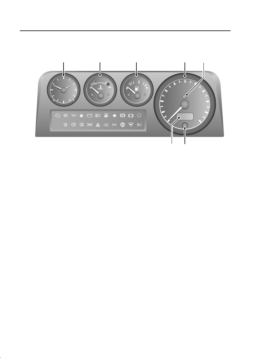
1. Speedometer
Indicates road speed in kilometres per hour.
2. Anti-theft alarm indicator light
Indicates the status of the alarm system (see
‘Anti-theft alarm indicator light’, page 26).
3. Total distance (odometer) and trip recorder
Indicates the total distance or the individual
journey distance travelled by the vehicle.
4. Trip recorder reset button
Briefly press and release the button to change
the digital display between either the total
distance travelled, or the individual journey
distance. Press and hold the button to reset the
trip recorder to zero.
5. Fuel gauge
The pointer indicates the fuel level when the
starter switch is turned to position ‘II’.
NOTE: When the fuel remaining drops to a
minimum of 9 litres, the low fuel warning light
will illuminate (see ‘WARNING LIGHTS’,
page 46).
567
40
ABS
TC
1
100
80
km/h
60
20
0
3
4
2
120
140
160
180
200
6. Temperature gauge
Once the engine coolant has reached its normal
operating temperature, the pointer should
remain between the BLUE and RED segments.
If the pointer moves towards the RED segment,
this indicates that the engine coolant is
becoming too hot. Should the pointer move
INTO the RED segment, severe engine damage
could occur. In this case, stop the vehicle as
soon as safety permits and allow the engine to
idle for five minutes in order to cool down - DO
NOT SWITCH OFF. Seek qualified assistance
before continuing.
7. Clock
For further information on setting the time on
the clock, see ‘CLOCK’, page 64.
8. Warning lights
For further information on the functionality of
the warning lights, see ‘WARNING LIGHTS’,
page 46.
45
Page 46

Warning Lights
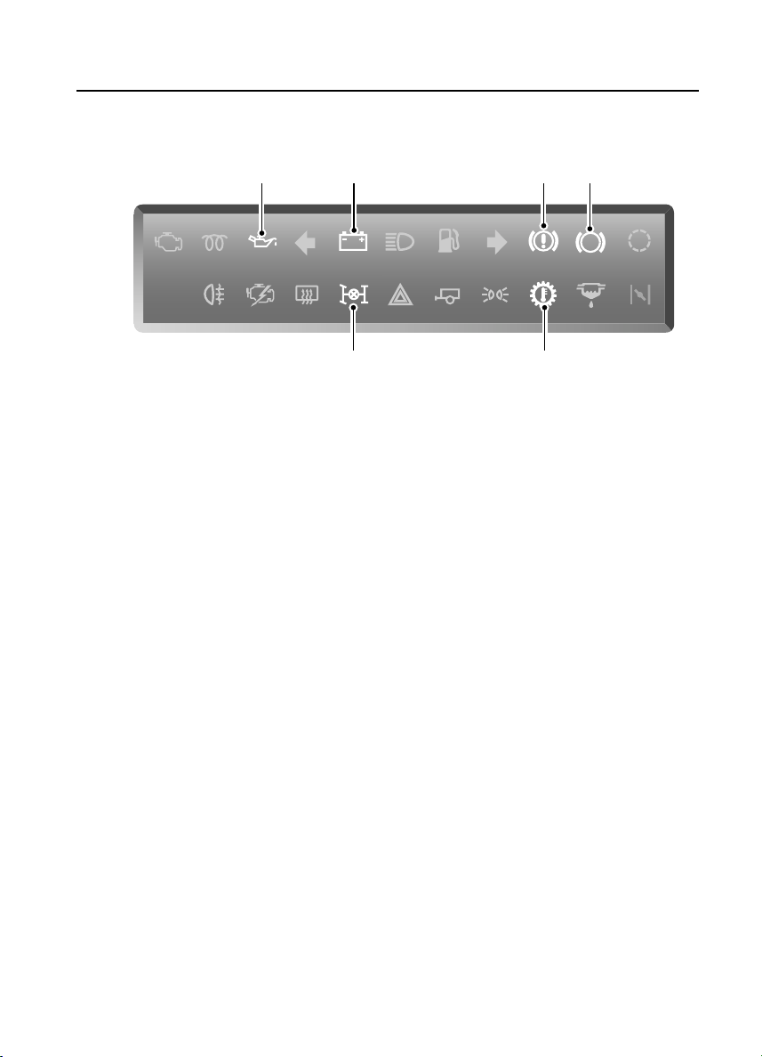
WARNING LIGHTS
120
km/h
H3723
Warning Lights
ABS
TC
The location and specification of the warning
lights may vary according to model and market
requirements.
WARNING
DO NOT drive if a RED warning light remains
on once the engine is running or illuminates
whilst driving.
Check engine - AMBER
The light illuminates as a bulb and
system check when the starter
switch is turned on, and
extinguishes as soon as the engine is started.
Illumination at any other time indicates an
engine fault - if the light illuminates while
driving, avoid high speeds and seek qualified
assistance urgently.
Glow plug - AMBER
Illuminates when the starter switch
is turned to position ‘II’. Wait for
the light to extinguish before
starting the engine.
*
Low oil pressure - RED
The light illuminates as a bulb
check when the starter switch is
turned to position ‘II’ and
extinguishes when the engine is started. If the
light remains on, flashes on and off, or
illuminates whilst driving, stop the vehicle as
soon as safety permits and SWITCH OFF
THE ENGINE IMMEDIATELY. Seek qualified
assistance before driving. Always check the oil
level when this light illuminates.
Direction indicators - GREEN
The left or right warning light
flashes in time with the
corresponding left or right
direction indicator lights whenever they are
operated. If the warning light fails to flash, or
flashes very rapidly, this may indicate a bulb
failure in one of the direction indicator lights.
If the hazard switch is pressed, both warning
lights will flash in conjunction with the direction
indicator lights.
Battery charging - RED
The light illuminates as a bulb
check when the starter switch
is turned to position ‘II’ and
extinguishes once the engine is running. If it
remains on, or illuminates whilst driving, a fault
is indicated. Seek qualified assistance urgently.
46
Page 47

Warning Lights
Headlight main beam - BLUE
Illuminates when the headlights
are switched to main beam.
Low fuel - AMBER
Illuminates when the fuel
remaining in the tank drops to a
minimum of 9 litres. If the light
illuminates, refuel at the first opportunity.
Handbrake, brake fluid - RED
The light illuminates for about
3 seconds as a bulb check when
the starter switch is turned on. It
also illuminates when the handbrake is applied
with the starter switch in position ‘II’. The light
should extinguish when the handbrake is fully
released or shortly after the electrical circuits
are switched on. If the light illuminates whilst
driving, a fault with the braking system is
indicated. Stop the vehicle as soon as safety
permits and seek qualified assistance before
continuing.
Anti-lock braking system - AMBER
Illuminates for approximately 1
second as a bulb and system check
when the starter switch is turned to
position ‘II’, and briefly extinguishes before
coming on again. If the light does not
extinguish and then come on again, then a fault
occurred with the ABS system and you should
consult a qualified dealer at the earliest
opportunity. The warning light will remain on
until the vehicle is driven above approximately
7 km/h.
If the light remains on or subsequently
illuminates while driving, a fault has been
detected by the self monitoring system. This
means that full ABS control may not be
available and you should consult your dealer at
the earliest opportunity.
*
Traction Control - AMBER
Illuminates as a bulb check when
the starter switch is turned to
position ‘II’ and extinguishes after
approximately 3 seconds. The light illuminates
for a minimum of 2 seconds, whenever traction
control is operating.
If the warning light flashes (for at least
10 seconds) traction control has been
operating for too long and has temporarily shut
down to allow the system to cool - this will only
occur in extreme conditions.
If the light illuminates continuously, a fault with
the system is indicated; seek qualified
assistance.
Rear fog guard lights - AMBER
Illuminates whenever the rear fog
guard lights are on.
NOTE: In clear conditions, rear fog guard lights
can dazzle other road users. Use ONLY when
visibility is severely restricted.
Engine immobilisation - RED
Flashes during any attempt to start
the engine when the engine is
immobilised.
Heated rear screen - AMBER
Illuminates when the rear screen
heater is operating.
Differential lock - RED
Illuminates whenever the
differential is locked. If the light
remains on after the differential
lock is disengaged, transmission ‘wind-up’ may
be present. Reversing for a short distance and
then going forward will usually ‘unwind’ the
transmission. If the light remains on, contact
your dealer as soon as possible.
*
*
*
47
Page 48

Warning Lights
Hazard warning lights - RED
Illuminates in conjunction with the
direction indicator warning lights,
when the hazard warning lights are
operated.
Trailer direction indicators - GREEN
The light illuminates briefly as a
bulb check when the starter switch
is turned to position ‘II’. If a trailer
is attached, the light illuminates in conjunction
with the vehicle direction indicator lights to
show that all trailer indicator lights are
functioning correctly. In the event of a bulb
failure on the trailer, the warning light flashes
once and then remains off.
Sidelights - GREEN
Illuminates whenever th e sidelights
are on.
Transmission oil temperature - RED*
Illuminates as a bulb check when
the starter switch is turned to
position ‘II’ and extinguishes after
3 seconds approx. If the light illuminates while
driving, the gearbox oil temperature is too high
(most likely to occur in very hot weather during
continuous high speed driving, or whilst towing
heavy loads on steep inclines or if the
handbrake has been applied while driving).
If the light illuminates, reduce speed. If the light
remains on, stop the vehicle and allow the
gearbox to cool. Do not drive until the light has
extinguished. (Depending on the ambient
temperature and the carrying loads imposed on
the vehicle, it may take several minutes before
the light extinguishes and it is safe to drive).
Fuel filter - AMBER
3 seconds approximately. If the light
illuminates while driving, this indicates the
presence of excessive amounts of water in the
fuel. You may continue driving but should seek
qualified assistance at the earliest convenient
time.
*
Illuminates as a bulb check when
the starter switch is turned to
position ‘II’ and extinguishes after
48
Page 49

Lights & Indicators
Lights & Indicators
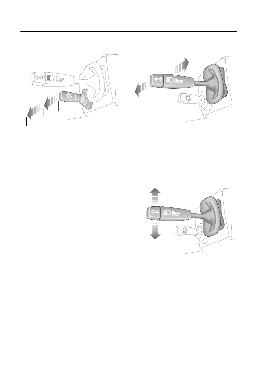
DIRECTION INDICATORS
H3629
Move the lever DOWN to indicate a LEFT turn,
and UP to indicate a RIGHT turn (the
appropriate GREEN warning light on the
instrument panel will flash in time with the
direction indicators).
Hold the lever part-way up or down against
spring pressure to indicate a lane change.
LIGHTS
0
1
2
H3632
Side, tail and instrument panel lights
Push the lighting switch to position 1.
Headlights
Push the lighting switch to position 2.
Headlight main and dipped beams
3630
With the headlights switched on, push the lever
away from the steering wheel to change
headlight beams (BLUE warning light glows
when the headlights are on main beam).
To flash the headlights, pull the lever part way
towards the steering wheel and release.
49
Page 50

Lights & Indicators
Headlight levelling
H3669
The angle of the headlight beams is affected by
the distribution of weight inside the vehicle. The
headlights should be adjusted so that the point
at which the beams meet the road surface
ahead of the vehicle provides adequate
illumination without dazzling other road users.
The four-position switch should be used to
adjust the headlight beams in relation to the
vehicle loadings identified opposite.
*
Position Loading Condition
0 Driver, or driver and front
passenger only
(loadspace empty).
1 All seats occupied
(loadspace empty)
2 All seats occupied with
loadspace loaded to max.
permissible rear axle weight.
3 Driver only with loadspace
loaded to max. permissible
rear axle weight.
Vehicles fitted with front seats only
Positions ‘1’ and ‘2’ should only be used when
required, according to the distribution and
weight of the load being carried.
50
Page 51

Lights & Indicators
FOG LIGHTS*
H3692
Rear fog guard lights
Press to operate, press a second
time to switch off (the indicator
light in the switch illuminates when
the fog guard lights are switched on). The rear
fog guard lights illuminate ONLY when the
headlights are also switched on, and the starter
switch is turned to position ‘II’. Switching off
the headlights, or turning the starter switch to
position ‘0’, will automatically extinguish the
rear fog guard lights too (the fog guard lights
will not illuminate again unless selected
manually).
ALWAYS remember to switch the fog guard
lights off as soon as visibility permits; in clear
conditions fog guard lights can dazzle other
road users!
HAZARD WARNING LIGHTS
H3693
Press to operate; all the direction
indicator lights (including those
fitted to a trailer) will flash
together. Use ONLY in an emergency to warn
other road users when your stationary vehicle
is causing an obstruction, or is in a hazardous
situation. Remember to switch off before
moving away.
51
Page 52

Wipers & Washers
H
Wipers & Washers
OPERATING
The wipers and washers will only operate when
the starter switch is turned to position ‘I’ or ‘II’.
IMPORTANT INFORMATION
• DO NOT operate the wipers on a dry
screen.
• In freezing or very hot conditions,
ensure that the blades are not frozen or
stuck to the glass.
• In winter, remove any snow or ice from
around the arms and blades, including
the wiped area of the windscreen and
the heater air intakes.
NOTE: If the wiper blades have stuck to the
glass, a thermal cut-out may temporarily
prevent the wiper motor from operating. If this
is the case, switch the wipers off, free them
from the obstruction and then switch on again.
WINDSCREEN WIPERS
3627
Intermittent wipe
Pull lever down.
Normal speed wipe
Push lever up to first position.
Fast speed wipe
Push lever up to second position.
Single wipe
H3626
Push the lever up against spring pressure and
release immediately.
NOTE: With the lever held up, the wipers will
continue operating at slow speed until it is
released.
52
Page 53

Wipers & Washers
WINDSCREEN WASHER
H3628
Press to operate. The windscreen wipers will
operate in conjunction with the washers for as
long as the lever is pressed, the wipers
continuing for a further 4 seconds after the
lever is released.
REAR WINDOW WIPER AND WASHER*
H3672
Rear window wiper
Press to operate: the wiper
operates continuously until the
switch is pressed again.
Rear window washer
Press and hold switch for the
required duration of window
washing. Washing stops as soon
as the switch is released.
53
Page 54

Horn
HORN
H3631
Press the end of the lever to operate the horn.
Horn
54
Page 55

Manual Windows
Manual Windows
FRONT AND REAR WINDOWS
Raise or lower the window by rotating the
handle mounted on the door trim pad.
SLIDING REAR WINDOWS*
H3609
To open, press the catch tongues together,
slide the window to the desired position and
release the catch, ensuring that it locates
securely in the sockets, locking the window in
position.
55
Page 56

Electric Windows
Electric Windows
ELECTRIC WINDOWS *
H3671
Operating the windows
The electric windows can be operated when the
starter switch is at position ‘II’ by pressing the
switches on the centre console as follows:
Press and HOLD the bottom of a switch to lower
and the top of a switch to raise. The window will
stop moving as soon as the switch is released.
WARNING
Accidental closing of an electrically operated
window on fingers, hands or any vulnerable
part of the body, can result in serious injury.
Always observe the following precautions:
ENSURE children are kept clear whilst raising
or lowering windows.
ENSURE that all adult passengers are familiar
with the controls and the potential dangers of
electrically operated windows.
DO NOT allow passengers to extend any part
of their bodies through a window aperture
while the vehicle is moving - injury from
flying debris, branches of trees or other
obstructions could occur.
56
Page 57

Sunroof
Sunroof
SUNROOF*
N
E
P
O
O
P
E
N
H3613
The sunroof can be opened to varying degrees
or, if required, can be removed completely.
• To OPEN the roof: Turn the hand wheel
anti-clockwise to give the desired opening.
• To CLOSE the roof: Turn the hand wheel
clockwise until resistance is felt.
WARNING
ENSURE the sunroof is not obstructed when
opening or closing.
To remove the sunroof
H3612
Open the sunroof fully and push the catch
rearwards (as arrowed in illustration) to
disengage the handwheel mechanism.
DO NOT allow passengers to extend any part
of their bodies through the sunroof aperture
while the vehicle is moving - injury from
flying debris, branches of trees or other
obstructions could occur.
ALWAYS close the roof when the vehicle is
unattended.
H3600
Remove the sunroof by tilting upwards and
lifting rearwards to disengage the two locating
lugs.
WARNING
DO NOT store the sunroof loose in the vehicle.
DO NOT remove the sunroof whilst the vehicle
is moving.
Refit the sunroof by following the same
procedure in reverse.
57
Page 58

Heating & Ventilation
mph
VENTILATION
Heating & Ventilation
12
39
6
LAND -
- ROVER
70
50
100
80
km/h
120
60
30
90
140
40
160
20
180
110
10
0
0
mph
H3759
The ventilation system provides fresh or heated
air to the interior of the vehicle.
NOTE: Always keep the exterior air intake grilles
clear of obstructions such as leaves, snow or
ice.
The temperature of the air supplied to the
windscreen and foot level vents is controlled by
the heater, while the fresh air vents in the upper
fascia provide fresh air only. The location of the
vents is shown in the illustration above.
Information concerning the operation of the
heating and ventilation system, appears on the
following pages.
Fresh air vents
H3719
To open the vents in the upper fascia, pull one
or both knobs out and push the levers
downwards. To close the vents, pull the knobs
out and raise the levers.
These vents provide unheated fresh air only.
58
Page 59

HEATER CONTROLS
Heating & Ventilation
2
1
H3680
NOTE: For vehicles fitted with an air
conditioning system, the controls and air
conditioning vents are described on a later page
(see ‘AIR CONDITIONING CONTROLS*’,
page 61).
1. Temperature control
Move the lever downwards (towards the RED
arrow) to increase air temperature, or upwards
(towards the BLUE arrow) to reduce air
temperature.
2. Air distribution control
• Lever fully up - windscreen vents only.
• Lever midway - foot level and windscreen
vents.
• Lever fully down - foot level vents (also
provides some air to the windscreen).
3
3. Air blower control
• Lever fully up - no air will enter the vehicle
through the windscreen and foot level vents.
• As lever is moved down - progressively
more air will enter the vehicle, depending
solely on the ram effect of the vehicle
moving through the air.
• Lever at bottom - gives the choice of the fan
operating at low or high speed.
59
Page 60

Heating & Ventilation
USING YOUR HEATER
The following examples of basic heater settings
are intended as a general guide; the air
distribution, temperature and air blower
controls can then be further adjusted to suit
your comfort requirements.
Always remember that full heating is not
available until the engine has reached its
normal operating temperature.
Maximum heating
H3681
• Temperature control - fully down.
• Air distribution control - midway.
• Air blower control - fully down.
• Fresh air vents - fully closed.
Demisting and defrosting
H3682
• Temperature control - fully down.
• Air distribution control - fully up.
• Air blower control - fully down.
• Fresh air vents - fully open for demisting
(fully closed for defrosting).
• Opening a window may improve demisting.
Maximum ventilation
H3683
• Temperature control - fully up.
• Air distribution control - fully down.
• Air blower control - fully down.
• Fresh air vents - fully open.
60
Page 61

Air Conditioning
Air Conditioning
AIR CONDITIONING CONTROLS*
1
H3685
2
1. On/off blower control
Rotate clockwise to the first position to turn on
the air conditioning. Rotate further (positions II
and III) to increase the flow of conditioned air
from the four vents in the lower fascia.
NOTE: The air conditioning will only operate
with the engine running.
2. Temperature control
Rotate clockwise (positions I to III) to obtain
progressively cooler air.
Air conditioning vents
H3756
The four air conditioning vents located in the
lower fascia can be adjusted to suit your
requirements. The adjuster in the centre of each
vent can be used to adjust volume and direction
of air. To cut off the supply of air from any
particular vent, slide the adjuster fully to the
left.
General operating notes
• For optimum operating efficiency, ensure all
the air conditioning vents are open.
• In very humid conditions, slight screen
misting may be experienced when the air
conditioning system is turned on. This is a
natural occurrence on most automotive air
conditioning systems. It is not a fault and
misting will clear after a few seconds once
the air conditioning system is operating.
• If the temperature inside the vehicle is
higher than that outside when you start the
engine, it will take time for the air
conditioning to become fully effective. It is
best to ventilate the vehicle by opening the
windows and setting the controls to
‘Maximum cooling’. When the vehicle has
been ventilated, close the windows and set
the blower controls for personal comfort.
• Operating the air conditioning takes power
from the engine and consequently increases
fuel consumption.
61
Page 62

Air Conditioning
• All air conditioning systems need to be
operated for a short while every week (even
in winter) to maintain them in peak
condition.
• Surplus water produced by the
dehumidifying process is expelled from the
system via drain tubes beneath the vehicle.
This may result in a small pool of water
forming on the road when the vehicle is
stationary and is not a cause for concern.
USING THE AIR CONDITIONING
Air conditioning provides additional cooling to
the vehicle interior and also reduces the
moisture content of the air.
It is important to keep windows, sunroof
fresh air vents closed during operation.
Air conditioning settings
H3686
* and
Normal cooling
H3689
Temperature control - set to positions I or II.
Blower control - set to desired speed.
Maximum cooling
H3691
Temperature control - set to position III.
Blower control - set to position III.
When air conditioning is to be used, ensure that
the fresh air vents are closed, and the heater
unit controls are set as shown, i.e.
Air blower control - position ‘0’.
Temperature control - fully up.
Distribution control - fully up.
The following examples of air conditioning
settings are included for your guidance.
62
Page 63

Heated Screens
Heated Screens
HEATED FRONT SCREEN AND REAR
WINDOW
H3742
Heated front screen*
indicator light extinguishes). After 8 minutes
continuous operation, the heater switches off
automatically. Note that the heated front screen
operates only with the engine running.
*
Press to operate (the indicator light
in the switch illuminates); press a
second time to switch off (the
WARNING
DO NOT stick labels over the heating
elements, and DO NOT scrape or use abrasive
materials to clean the inside of the window.
Heated rear window
the heating elements are switched on and
extinguishes when they are turned off.
*
Press to operate; press a second
time to switch off. The indicator
light in the switch illuminates while
63
Page 64

Interior Equipment
INTERIOR LIGHTS
Interior Equipment
CLOCK
OFF
N
O
H2592
Switch positions:
• ‘OFF’ - Light permanently off.
• ‘ON’ - Light illuminates continuously.
With the switch in the centre position, the
interior light illuminates automatically
whenever a door is opened or the alarm system
is disarmed. The light remains illuminated for
15 seconds after the doors are closed, or until
the starter switch is turned on.
NOTE: Any subsequent opening and shutting of
doors prior to the starter switch being turned
on again, will cause the 15 second delay feature
to operate.
On Station Wagon models, illumination of the
interior lights is also activated by opening and
closing the tail door.
12
9
3
6
H3625
To adjust the time, use a ballpoint pen or similar
probe to advance or put back the time, by
pressing in the left or right hand buttons at the
bottom of the clock bezel.
NOTE: The clock will need to be reset if the
battery is disconnected.
After driving, the interior lights will fade and
then extinguish as soon as the vehicle is locked
or when the last door is closed.
NOTE: When the light is switched for automatic
operation (switch in centre position), a
‘time-out’ function extinguishes the lights after
8 minutes approx. if a door is left open, to
prevent the battery from discharging.
64
Page 65

H3668
Interior Equipment
CIGAR LIGHTER*
With the starter switch turned on, press the
lighter in to heat up. When it has reached the
correct temperature it will partially eject and
can then be withdrawn for use.
• ONLY hold the cigar lighter by the handle.
• DO NOT plug accessories into the cigar
lighter socket unless they are approved by
Land Rover.
ASHTRAY
WARNING
DO NOT use the ashtray for disposing of waste
paper or other combustible items.
Lift the lid of the ashtray to open. To remove,
carefully prise the body of the ashtray out of the
fascia panel.
65
Page 66

Interior Equipment
CUBBY BOX*
H4299
To open the cubby box, lift up the catch on the
lid.
There are two cup holders in the front of the
cubby box base.
WARNING
•
The driver should not drink and should not
use the cup holder when driving.
•
If the cup holder is retractable , it should
be kept closed when not in use.
•
DO NOT place anything other than suitable
drinks containers in the cup holder,
because such items may be thrown about
in the compartment and possibly injure
occupants in the event of an accident or
emergency manoeuvre.
•
Do not carry open-top drinks containers in
the cup holders while the vehicle is in
motion; a spilled hot drink could cause
personal injury. Spilled drinks can also
damage upholstery, carpeting and
electrical components.
•
Use only soft containers. DO NOT use to
hold cups made of glass, china or hard
plastic as these may cause injury in the
event of an accident or emergency
manoeuvre. Unopened, sealed containers
(drinks cans, for example) are hard
objects and may also cause injury.
IN-CAR TELEPHONES
For your safety
WARNING
Using any hand-held appliance while driving
can be dangerous. Always stop the vehicle
before making a call and ensure the
telephone is switched off while you are
driving.
66
Page 67

Interior Equipment
INTERIOR REAR-VIEW MIRROR
H3649
The manual rear view mirror can be dipped to
reduce glare from the headlights of following
vehicles. At night, move the lever at the base of
the mirror forward to ‘dip’ the mirror. Normal
visibility is restored by pulling the lever back
again.
WARNING
In some circumstances the view reflected in a
‘dipped’ manual mirror can confuse the driver
as to the precise location of following
vehicles. Remember to take additional care!
LUGGAGE ANCHOR POINTS
H4731
Six fixing points are provided in the rear
luggage compartment floor to assist in safely
securing large items of luggage.
A net and strap luggage restraining system is
available as an accessory from your Land Rover
Dealer/Authorised Repairer.
67
Page 68

Exterior Equipment
STEPS*
H3653
Exterior Equipment
Rear step
H3660
Side steps
The side and tail door steps are hinged to
enable them to be folded down when in use, or
up when not required.
68
Page 69

In-Car Entertainment
In-Car Entertainment
RADIO AERIAL
H3673
Set into the front wing, the telescopic aerial can
be raised or lowered manually.
RADIO CASSETTE PLAYER
Full operating instructions for any audio
equipment fitted as standard to your vehicle,
are contained in the ‘In-Car Entertainment’ book
in the vehicle literature pack.
69
Page 70

70
Page 71

Driving & Operating
Starting & Driving
STEERING COLUMN LOCK . . . . . . . . . . . . . . . . . 73
STARTER SWITCH. . . . . . . . . . . . . . . . . . . . . . . . 73
STARTING - Diesel engines . . . . . . . . . . . . . . . . . 74
DRIVING . . . . . . . . . . . . . . . . . . . . . . . . . . . . . . . 75
FUEL ECONOMY . . . . . . . . . . . . . . . . . . . . . . . . . 76
AUXILIARY EQUIPMENT . . . . . . . . . . . . . . . . . . . 77
EMISSION CONTROL SYSTEM . . . . . . . . . . . . . . 77
Catalytic Converter
CATALYTIC CONVERTER. . . . . . . . . . . . . . . . . . . 78
Fuel Filling
SAFETY ON THE FORECOURT. . . . . . . . . . . . . . . 79
FUEL FILLER . . . . . . . . . . . . . . . . . . . . . . . . . . . . 79
TYPE OF FUEL . . . . . . . . . . . . . . . . . . . . . . . . . . . 80
FUEL FILLING . . . . . . . . . . . . . . . . . . . . . . . . . . . 81
EMPTY FUEL TANK . . . . . . . . . . . . . . . . . . . . . . . 81
FUEL CUT-OFF SWITCH (Td5 models). . . . . . . . . 82
Manual Gearbox
GEAR LEVER . . . . . . . . . . . . . . . . . . . . . . . . . . . . 83
Transfer Gearbox
TRANSFER GEARBOX . . . . . . . . . . . . . . . . . . . . . 84
USING THE TRANSFER BOX . . . . . . . . . . . . . . . . 84
THE DIFFERENTIAL LOCK . . . . . . . . . . . . . . . . . . 85
Brakes
FOOT BRAKE . . . . . . . . . . . . . . . . . . . . . . . . . . . . 87
HANDBRAKE . . . . . . . . . . . . . . . . . . . . . . . . . . . . 88
ANTI-LOCK BRAKES . . . . . . . . . . . . . . . . . . . . . . 88
Traction Control
ELECTRONIC TRACTION CONTROL. . . . . . . . . . . 90
Towing
TOWING. . . . . . . . . . . . . . . . . . . . . . . . . . . . . . . . 91
Cab Pick-up
SPARE WHEEL. . . . . . . . . . . . . . . . . . . . . . . . . . . 94
TAILGATE OPERATION . . . . . . . . . . . . . . . . . . . . 94
FITTING AND REMOVING THE CANOPY . . . . . . . 95
Fitting. . . . . . . . . . . . . . . . . . . . . . . . . . . . . . . . . . 95
Removal. . . . . . . . . . . . . . . . . . . . . . . . . . . . . . . . 97
CLEANING THE CANOPY . . . . . . . . . . . . . . . . . . . 98
LOAD AREA . . . . . . . . . . . . . . . . . . . . . . . . . . . . . 98
REAR WINDOW. . . . . . . . . . . . . . . . . . . . . . . . . . 98
FRONT FENDER - CHECKER PLATE. . . . . . . . . . . 98
WINDSCREEN PROTECTION RAIL. . . . . . . . . . . . 98
71
Page 72

SIDE BARS . . . . . . . . . . . . . . . . . . . . . . . . . . . . . 98
Load Carrying
LUGGAGE SPACE . . . . . . . . . . . . . . . . . . . . . . . . 99
ROOF RACKS . . . . . . . . . . . . . . . . . . . . . . . . . . . 99
Ancillary Equipment
WINCHES . . . . . . . . . . . . . . . . . . . . . . . . . . . . . 100
POWER TAKE-OFF DRIVES. . . . . . . . . . . . . . . . 101
HAND THROTTLE . . . . . . . . . . . . . . . . . . . . . . . 102
72
Page 73

Starting & Driving
Driving & Operating
Starting & Driving
STEERING COLUMN LOCK
H3584
To unlock the steering column
Insert the key FULLY and turn the starter switch
to position ‘I’. A small movement of the steering
wheel may be necessary to disengage the
steering lock while turning the switch.
To lock the steering column
Turn the key to position ‘0’ and withdraw it
from the starter switch. Turn the steering wheel
slightly until the lock engages.
WARNING
Once the steering lock is engaged, it is
impossible to steer the vehicle. DO NOT
remove the key or turn the starter switch to
position ‘0’ while the vehicle is in motion.
STARTER SWITCH
The starter switch is located to the left of the
steering column, and uses the following
sequence of key positions to operate the
steering lock, electrical circuits and starter
motor:
Position ‘0’
• Steering locked (if key is removed).
• Most lighting circuits are operational,
including: sidelights, headlights and hazard
warning lights.
Position ‘I’
• Steering unlocked.
• Radio/cassette player can be operated.
Position ‘II’
• All instruments, warning lights and
electrical circuits are operational.
Position ‘III’
• Starter motor operates.
Release the key immediately the engine
starts (the key will automatically return to
position ‘II’). Note that operation of position
‘I’ electrical functions will be interrupted
during engine cranking.
73
Page 74

Starting & Driving
STARTING - Diesel engines
WARNING
Never start or leave the engine running in an
unventilated building - exhaust gases are
poisonous and contain carbon monoxide,
which can cause unconsciousness and may
even be fatal.
Before starting the engine and driving, ENSURE
you are familiar with the precautions shown
under ‘CATALYTIC CONVERTER*’, page 78.
In particular, you should be aware that if the
engine fails to start, continued use of the starter
may result in unburnt fuel damaging the
catalytic converter.
1. Check that the handbrake is applied and
that the gear lever is in neutral.
2. Switch off all unnecessary electrical
equipment.
3. Insert the starter key and turn the switch
to position ‘II’. Wait until the glow plug
warning light extinguishes.
NOTE: The waiting time will vary
according to the engine coolant
temperature (when the engine is hot, the
glow plug warning light will extinguish
almost immediately).
4. Turn the key to position ‘III’ to operate the
starter motor. DO NOT press the
accelerator pedal while starting. RELEASE
THE KEY as soon as the engine is running.
NOTE: Continued use of the starter will not only
discharge the battery, but may cause damage to
the starter motor.
NOTE: In temperate climates, the battery
charging and oil pressure warning lights should
extinguish as soon as the engine is running.
In cold weather, or when the battery is in a low
state of charge, depress the clutch pedal while
starting and hold it down until the engine is
running. This will reduce the load on the
battery.
Precautions
• The diesel engine must not be run above
idle speed until the oil pressure warning
light extinguishes. This will ensure that
the engine and turbo-charger bearings are
properly lubricated before being run at
speed.
• Similarly, ALWAYS allow the engine to
idle for 10 seconds before switching off.
Cold climates
In very cold climates the oil pressure warning
light may take several seconds to extinguish.
Similarly, engine cranking times will also
increase; at -30°C the starter motor may need
to be operated continuously for as long as 30
seconds before the engine will start. For this
reason, ensure that all non-essential electrical
equipment is switched off.
If the engine stalls or fails to start, you MUST
return the starter switch to position ‘I’ before
attempting to restart; the engine will not start by
turning the starter switch from position ‘II’.
In temperate climates DO NOT operate the
starter for longer than 10 seconds. If the engine
fails to start, switch off and wait 10 seconds
before re-using the starter.
74
Page 75

Starting & Driving
DRIVING
IMPORTANT INFORMATION
Vehicle stability
Your vehicle has a higher ground clearance
and, hence, a higher centre of gravity than
ordinary passenger cars to enable the
vehicle to perform in a wide variety of
different off-road applications. An
advantage of the higher ground clearance
is a better view of the road, allowing the
driver to more easily anticipate problems.
Inexperienced drivers should take
additional care, remembering that the
vehicle is not designed for cornering at the
same speeds as conventional passenger
cars, any more than a low slung sports car
is designed to perform satisfactorily in
off-road conditions. As with other vehicles
of this type, failure to operate the vehicle
correctly may result in loss of control or
even rollover.
Vehicle height
The overall height of your vehicle exceeds
that of ordinary passenger cars. Always be
aware of the height of your vehicle and
check the available headroom before
driving through low entrances. This is
particularly important if the vehicle is fitted
with a roof rack or if a sunroof is open.
Instruments and warning lights
Before driving it is important to fully
understand the function of the instruments and
warning lights (see ‘INSTRUMENT PANEL’,
page 45).
NOTE: Red warning lights are of particular
importance, illumination indicating that a fault
exists. If a red light illuminates, always stop the
vehicle and seek qualified assistance before
continuing.
Warming-up
DO NOT warm-up the engine by allowing it to
idle at a slow speed. However, remember that
the diesel engine must not be run above idle
speed until the oil pressure warning light
extinguishes.
In the interests of fuel economy, it is advisable
to drive the vehicle straight away, as soon as
the oil pressure warning light extinguishes.
Remember that harsh acceleration and
labouring the engine before the normal
operating temperature has been reached can
damage the engine.
Running-in
Proper running-in will have a direct bearing on
the reliability and smooth running of your
vehicle throughout its life.
In particular, the engine, gearbox, brakes and
tyres need time to ‘bed-in’ and adjust to the
demands of everyday motoring. During the first
800 km, it is essential to drive with
consideration for the running-in process and
heed the following advice:
• LIMIT maximum road speed to 80 km/h.
Initially, drive the vehicle on a light throttle
and only increase engine speeds gradually
once the running-in distance has been
completed.
• DO NOT operate at full throttle or allow the
engine to labour in any gear.
• AVOID fast acceleration and heavy braking
except in emergencies.
75
Page 76

Starting & Driving
Power assisted steering
Power assistance is progressively applied the
more the steering wheel is turned. For example;
where manual steering effort would normally be
greatest (at slow speeds on maximum lock),
power assistance is greatest. Similarly, where
only minimal steering effort would normally be
required (at high speed with the wheels straight
ahead), then power assistance is also minimal,
thus enabling the driver to benefit from
apparently consistent steering effort at all
times.
WARNING
Under no circumstances must the steering
wheel be held on full lock for more than thirty
seconds in one minute, otherwise the
steering assembly may be damaged.
NOTE: Power assistance is dependent on the
engine running. If the engine is not running,
greater effort will be required to steer the
vehicle.
FUEL ECONOMY
Fuel consumption is influenced by two major
factors:
• How your vehicle is maintained.
• How you drive your vehicle.
To obtain optimum fuel economy, it is essential
that your vehicle is maintained in accordance
with the manufacturer's service schedule.
Items such as the condition of the air cleaner
element, tyre pressures and wheel alignment
will have a significant effect on fuel
consumption. But, above all, the way in which
you drive is most important. The following hints
may help you to obtain better value from your
motoring:
• Avoid unnecessary, short, start-stop
journeys.
• Avoid fast starts by accelerating gently and
smoothly from rest.
• Do not drive in the lower gears for longer
than necessary.
• Decelerate gently and avoid sudden and
heavy braking.
• Anticipate obstructions and adjust your
speed accordingly well in advance.
• When stationary in traffic, select neutral to
improve fuel economy and air conditioning
performance.
76
Page 77

Starting & Driving
AUXILIARY EQUIPMENT
WARNING
DO NOT use auxiliary equipment, such as
roller generators, that are driven by one
wheel of the vehicle, as they could cause
failure of the gearbox differential. If the
differential lock is engaged in an attempt to
avoid damage, the vehicle will drive itself
forward.
EMISSION CONTROL SYSTEM
WARNING
Exhaust fumes contain poisonous substances
which can cause unconsciousness and may
even be fatal.
•
DO NOT inhale exhaust gases.
•
DO NOT start or leave the engine running
in an enclosed unventilated area, or drive
with the taildoor open.
•
DO NOT modify the exhaust system from
the original design.
•
ALWAYS repair exhaust system leaks
immediately.
• If you think exhaust fumes are entering the
vehicle have the cause determined and
corrected immediately.
Land Rover vehicles are fitted with emission
and evaporative control equipment necessary
to meet a number of territorial requirements.
In many countries it is against the law for
vehicle owners to modify or tamper with
emission control equipment, or to sanction the
unauthorised replacement or modification of
this equipment. In such cases the vehicle owner
and the repairer may both be liable for legal
penalties.
It is important to remember that all Land Rover
Dealers/Authorised Repairers are properly
equipped to perform repairs and to maintain the
emission control system on your vehicle.
77
Page 78

Catalytic Converter
Catalytic Converter
CATALYTIC CONVERTER*
The exhaust system on some vehicles
incorporates a catalytic converter, which
converts poisonous exhaust emissions from
the engine into environmentally less harmful
gases.
WARNING
Catalytic converters can be easily damaged
through improper use, particularly if the
wrong fuel is used, or if an engine misfire
occurs. For this reason it is VERY IMPORTANT
that you heed the precautions which follow.
Fuel
ONLY use fuel recommended for your vehicle
(see ‘ENGINES’, page 174).
Starting the engine
• DO NOT continue to operate the starter after
a few failed attempts (unburnt fuel may be
drawn into the exhaust system, thereby
poisoning the catalyst), and do not attempt
to clear a misfire by pressing the accelerator
pedal - seek qualified assistance.
• When starting a COLD engine, DO NOT drive
if a misfire is suspected and do not attempt
to clear a misfire by pressing the accelerator
- seek qualified assistance.
• Do not attempt to push or tow-start the
vehicle.
Driving
• If a misfire is suspected, or the vehicle lacks
power while driving, provided the engine
has reached its normal operating
temperature, it may be driven SLOWLY (at
risk of catalyst damage) to a Land Rover
Dealer/Authorised Repairer for assistance.
• NEVER allow the vehicle to run out of fuel
(the resultant misfire could damage the
catalyst).
• Consult your Dealer/Authorised Repairer if
your vehicle is burning excessive oil (blue
smoke from the exhaust), as this will
progressively reduce catalyst efficiency.
• On rough terrain do not allow the underside
of the vehicle to be subjected to heavy
impacts which could damage the catalytic
converter.
• DO NOT overload or excessively ‘rev’ the
engine.
• DO NOT switch off the engine when the
vehicle is in motion with a drive gear
selected.
WARNING
Exhaust system temperatures can be
extremely high - DO NOT park on ground
where combustible materials such as dry
grass or leaves could come into contact with
the exhaust system - in dry weather a fire
could result.
Vehicle maintenance
Any engine misfire, loss of engine performance
or engine run-on, could seriously damage the
catalytic converter. For this reason, it is vital
that unqualified persons do not tamper with the
engine, and that regular systematic
maintenance is carried out by a Land Rover
Dealer/Authorised Repairer.
78
Page 79

Fuel Filling
SAFETY ON THE FORECOURT
Fuel Filling
FUEL FILLER
WARNING
Petroleum gases are highly inflammable and,
in confined spaces, are also extremely
explosive.
Always take sensible precautions when
refuelling:
• Switch off the engine.
• Do not smoke or use a naked flame or light,
or operate a mobile phone.
• Take care not to spill fuel.
• Do not overfill the tank.
WARNING
DO NOT fully remove the filler cap until any
captive tank pressure has been released (wait
until the hissing stops).
H3637
The fuel filler is located in the rear right-hand
body side. To unlock the fuel cap:
1. Insert the smaller metal key and turn it
90 degrees clockwise.
2. Turn the key 90 degrees anti-clockwise
and then remove.
The cap should then be unscrewed gradually,
as it is designed to allow the fuel tank to vent
during the first half turn. Carefully loosen the
cap one half turn until resistance is felt, and
allow fuel tank pressure to be released. Once
the pressure is released (hissing has stopped),
it is safe to fully remove the filler cap.
79
Page 80

Fuel Filling
H3638
When replacing the filler cap, ensure that the
key is removed from the lock, then tighten the
cap clockwise until you hear the fuel cap ratchet
click at least three times. This locks the cap (the
key is not needed). Finally, reposition the key
cover over the lock.
TYPE OF FUEL
WARNING
The diesel engines used in these vehicles are
not compatible with Bio-diesel fuel!
Use diesel to EN 590.
The quality of diesel fuel (Derv) can vary in
different countries and only clean, good quality
fuel should be used. It is important that the
sulphur content of diesel fuel does not exceed
0.3%; in Europe all supplies should be within
this limit, but in other parts of the world, you
should check with your supplier.
Ensure the fuel filter element is changed and the
fuel sedimenter drained, at the recommended
service intervals.
If good quality diesel fuel is unavailable and it is
necessary to use poor quality fuel, it may be
necessary to have the fuel filter/sedimenter
drained regularly.
NOTE: The use of paraffin (kerosene) as a diesel
fuel additive is illegal in the UK.
WARNING
If the fuel tank is accidentally filled with
petrol it is ESSENTIAL that you contact your
Dealer/Authorised Repairer BEFORE
attempting to start the engine!
80
Page 81

Fuel Filling
FUEL FILLING
WARNING
DO NOT attempt to fill the tank to its maximum
capacity. If the vehicle is to be parked on a
slope, in direct sunlight, or high ambient
temperature, expansion of the fuel could
cause spillage.
Filling station pumps are equipped with
automatic cut-off sensing to avoid fuel spillage.
Fill the tank SLOWLY until the filler nozzle
automatically cuts-off the supply. DO NOT
attempt to fill the tank beyond this point or
spillage could result due to expansion of the
fuel.
The diesel pumps on garage forecourts fill at a
maximum of 45 litres per minute. Use of
commercial vehicle diesel pumps with a higher
fill rate, may result in premature pump cut-off
and fuel spillage.
EMPTY FUEL TANK
Td5 diesel engine vehicles*
After running the fuel tank dry, refuel the tank
with at least 4.5 litres of diesel fuel, then carry
out the following procedure:
1. Turn off the starter switch and wait for 15
seconds.
2. Turn the starter key to position ‘II’ and wait
for 30 seconds.
3. Repeat steps 1 and 2 six times.
4. After the final 30 second period, fully
depress the accelerator pedal.
5. Keeping the pedal depressed, start
cranking the engine.
6. Continue cranking the engine and as soon
as the engine is firing smoothly, ease the
accelerator pedal back to approximately
halfway through its travel, and release the
starter key. The engine should now be
running.
7. If the engine fails to start, repeat the
process.
During the above procedure, the fuel pump will
be heard to operate (priming the engine). This
noise is not cause for concern.
IMPORTANT INFORMATION
The engine must NOT be cranked for more
than 20 seconds in any one period.
If the above procedure is carried out on a
vehicle that has NOT run out of fuel, it will
result in the engine flooding with fuel
and failing to start.
Tdi diesel engine vehicles
If the vehicle runs out of fuel, then qualified
assistance may be required to prime the fuel
system before the engine can be restarted.
81
*
Page 82

Fuel Filling
FUEL CUT-OFF SWITCH (Td5 models)
H3582
The fuel cut-off switch is a safety device which,
in the event of a collision or sudden impact,
automatically cuts off the fuel supply to the
engine.
The switch is located on the engine
compartment bulkhead. After an impact, the
switch must be reset by pressing the rubber top
(arrowed in illustration) before the engine can
be restarted.
WARNING
ALWAYS check for fuel leaks before resetting
the switch!
82
Page 83

Manual Gearbox
Manual Gearbox
GEAR LEVER
135
24R
H3749
Manual transmission vehicles feature a five
speed main gearbox and a two-speed (LOW &
HIGH) transfer box. In addition, a centre
differential in the transfer box distributes the
drive to the front and rear axles, providing
permanent four wheel drive. By using the main
gearbox in conjunction with the transfer gears,
ten forward and two reverse speeds are
available.
The gear positions for the main gearbox are
shown on the gear lever knob. Note that when
the gearbox is in neutral, the gear lever is
spring-loaded to lie naturally between third and
fourth gear positions.
Precautions while driving
• DO NOT rest your hand on the gear lever
while driving - pressure from your hand
may cause premature wear to the gear
selector mechanism.
• DO NOT use the clutch pedal as a foot rest.
To prevent unnecessary wear, always keep
the left foot well clear of the clutch pedal
except when changing gear.
• DO NOT hold the vehicle stationary on a hill
by slipping the clutch. This will wear out the
clutch. Always use the handbrake.
WARNING
Do not select reverse gear unless the vehicle
is stationary.
Do not attempt to start the engine with the
vehicle in gear. The engine must ONLY be
started with the main gear lever in neutral and
the handbrake applied.
83
Page 84

Transfer Gearbox
Transfer Gearb ox
TRANSFER GEARBOX
L
DIFF
LOCK
H3607
The second gearbox (known as the transfer
box) is used to select either the high or low
range of gears. It also has a neutral position
between high and low.
High range (‘H’)
High range should be used for all normal road
driving and also for off-road driving across dry,
level terrain.
Low range (‘L’)
Low range should be used ONLY in situations
where low speed manoeuvring is necessary,
such as reversing a trailer or negotiating a
boulder-strewn river bed. Also use Low range
for more extreme off-road conditions where
progress in High range cannot be maintained.
DO NOT attempt to use LOW range gears for
normal road driving.
Neutral (‘N’)
With the transfer box in neutral, drive cannot be
transmitted to the road wheels, regardless of
the position of the main gear lever. Use transfer
gearbox Neutral when being towed.
N
H
USING THE TRANSFER BOX
There are two ways of operating the transfer
box lever:
1. ‘Statically’ i.e., shifting while the vehicle is
stationary,
2. ‘Shift on the move’; this is the
recommended method, which, after a little
practice, can be carried out smoothly and
quickly.
‘Static’ method
With the vehicle stationary and the engine
running, depress the clutch and then move the
lever fully forwards (or backwards) in TWO
distinct but positive moves - ‘high to
neutral’......’neutral to low’ (or vice versa).
If there is resistance to the gear engaging - from
the neutral position to either high or low, do not
force the lever. Instead:
1. Still with the clutch depressed (and the
transfer box in neutral), select 2nd gear in
main gearbox.
2. Release the clutch momentarily, depress
the clutch and then try engagement again.
3. Select appropriate main gearbox gear to
pull away.
Changing from high to low on the move
With the vehicle slowing to a stop and travelling
NO FASTER THAN 8 km/h, depress the clutch
and move the transfer lever into neutral. Just
before the road wheels stop turning (and with
the clutch still depressed) push the lever fully
forward into ‘L’ (low).
NOTE: Use positive and confident moves, but
do not rush the gear change.
84
Page 85

Transfer Gearbox
Changing from low to high on the move
Changing from ‘L’ (low) to ‘H’ (high) can be
achieved without stopping the vehicle, as
follows:
1. Apply slight backward pressure to the
transfer gear lever in preparation for
changing.
2. Then, in three simultaneous moves,
depress the clutch, release the accelerator
and pull the transfer lever into neutral.
3. Release the clutch pedal for approximately
3 seconds before depressing it again and
moving the transfer lever firmly into the
high position.
4. Finally, select a suitable main gear, release
the clutch and continue driving in the
normal way.
THE DIFFERENTIAL LOCK
3608
Unlike many four wheel drive vehicles, all Land
Rover vehicles have permanent four-wheel
drive. This is achieved by the inclusion of a
lockable differential between the front and rear
drive shafts. With the differential locked, the
drive shafts to front and rear axles are (in effect)
joined together, causing both to rotate at the
same speed. This is a normal feature with all
four-wheel drive vehicles and enhances traction
on difficult off-road surfaces. However, with the
differential unlocked, the different running
requirements of the two axles can be
accommodated, thereby enabling Land Rover
vehicles to operate permanently in four-wheel
drive for both road AND off-road use.
Selecting diff lock
The diff lock can be engaged or disengaged
either with the vehicle stationary, or when
driving at any road speed. However, with the
vehicle in motion, it is ESSENTIAL to be
travelling on firm ground, in a straight line, and
without wheel slip.
85
Page 86

Transfer Gearbox
WARNING
DO NOT engage the diff lock if one or more
wheels are slipping - this could damage the
transmission. If wheels are slipping, ease off
the accelerator before engaging the diff lock.
DO NOT engage the diff lock from the transfer
neutral position.
To lock the differential:
Briefly ease the throttle and move the transfer
gear lever to the left - from either ‘H’ (high) or
‘L’ (low) position (the warning light on the
instrument panel will illuminate).
To unlock the differential:
Move the transfer gear lever to the right - to
either ‘H’ (high) or ‘L’ (low) position as
required; when the diff lock disengages, the
warning light will extinguish.
When to use the diff lock
As a general rule, the differential should only be
locked in order to drive off-road on loose and
slippery surfaces. ALWAYS unlock the
differential for normal road driving or as soon
as a hard grippy surface is reached, whether
high or low gears are selected.
NOTE: A valuable introduction to off-road
driving, which includes many useful references
to the transfer gearbox and the diff lock, is
included in the ‘Off-road driving’ section of this
handbook.
Diff lock warning light
The amber warning light in the
instrument panel illuminates when
the diff lock is actually engaged rather than when it has been selected. Similarly,
it will only extinguish when the diff lock is
actually disengaged. This accounts for a slight
delay between diff lock deselection and the
warning light extinguishing, which is quite
normal.
IMPORTANT INFORMATION
Transmission ‘wind up’
If the warning light is obviously reluctant to
extinguish after the diff lock has been
deselected, some transmission ‘wind up’
may be present.
Reversing the vehicle a short distance and
then going forward will usually ‘unwind’
the transmission and extinguish the light
and the vehicle can be driven as normal.
However, if after two or three attempts to
‘unwind’ the transmission the light remains
on, consult your dealer AS SOON AS
POSSIBLE.
WARNING
DO NOT drive the vehicle at speeds in excess
of 60 km/h with the differential locked.
WARNING
If the vehicle is driven on normal road
surfaces with the differential locked, the
steering will feel stiff, excessive tyre wear
will occur and the transmission will be
‘wound up’. This places excessive strain on
the transmission.
86
Page 87

Brakes
Brakes
FOOT BRAKE
For your safety, the hydraulic braking system
operates through dual circuits. If one circuit
should fail, the other will continue to function.
However, in the event of brake failure where
only one circuit is operational, the vehicle
should only be driven at slow speed to the
nearest qualified dealer. In these
circumstances, exercise extreme caution and
be aware that increased brake pedal travel,
greater pedal pressure, and longer stopping
distances will be experienced.
Servo assistance
The braking system is servo assisted, but ONLY
when the engine is running. Without this
assistance greater braking effort is necessary to
safely control the vehicle, resulting in longer
stopping distances. Always observe the
following precautions:
• NEVER allow the vehicle to freewheel with
the engine turned off.
• ALWAYS take particular care when being
towed with the engine turned off.
• If the engine should stop for any reason
while the vehicle is in motion, bring the
vehicle to a halt as quickly as traffic
conditions safely allow, and DO NOT pump
the brake pedal as the braking system may
lose any remaining assistance available.
Brake warning light
If the warning light in the
instrument panel illuminates
while driving, and the handbrake
is fully released, a fault with the braking system
is indicated. Check the brake fluid level; if the
light continues to illuminate, seek qualified
assistance before continuing.
Brake pads
Brake pads require a period of bedding in. For
the first 800 km, you should avoid situations
where heavy braking is required.
Remember! Regular servicing is vital to ensure
that the brake pads are examined for wear and
changed periodically to ensure long-term safety
and optimum performance.
WARNING
DO NOT rest your foot on the brake pedal
while travelling as this may overheat the
brakes, reduce their efficiency and cause
excessive wear.
NEVER move a vehicle without the engine
running because braking assistance will not
be available. The pedal brakes will still
function, but more pressure will be required
to operate them.
If the brake warning light should illuminate
while the vehicle is in motion, bring the
vehicle to a halt as quickly as traffic
conditions and safety permit and seek
qualified assistance before continuing.
DO NOT pump the brake pedal - the braking
system may lose any remaining servo
assistance available.
Wet conditions
Driving through water or even very heavy rain
may adversely affect braking efficiency. Always
dry the braking surfaces by intermittent light
application of the brakes, first ensuring that you
are at a safe distance from other road users.
87
Page 88

Brakes
HANDBRAKE
Unlike most other vehicles, the handbrake
operates on the rear propeller shaft, and NOT
on the road wheels. This may result in slight
movement of the vehicle after the handbrake is
applied.
To engage the handbrake, pull the lever up fully.
To release, pull the lever up slightly, depress
the button and lower the lever.
Always apply the handbrake fully whenever
you park.
When parking on a slope, do not rely on the
handbrake alone to hold the vehicle, park in a
low forward gear when facing uphill and in
reverse gear when facing downhill. For extra
security on steep slopes, move the transfer
lever into low range or engage the diff lock.
WARNING
DO NOT apply the handbrake while the
vehicle is in motion as this could result in loss
of vehicle control and damage to the
transmission.
DO NOT rely on the handbrake to operate
effectively if the vehicle has been subjected
to immersion in mud and water (see ‘Off-road
driving’ section).
ANTI-LOCK BRAKES*
WARNING
ABS cannot overcome the physical limitations
of stopping the vehicle in too short a distance,
cornering at too high a speed, or the danger of
aquaplaning, i.e. where a layer of water
prevents adequate contact between the tyres
and the road surface.
The fact that a vehicle is fitted with ABS must
never tempt the driver into taking risks that
could affect his/her safety or that of other road
users. In all cases, it remains the driver's
responsibility to drive within normal safety
margins, having due consideration for
prevailing weather and traffic conditions.
The driver should always take account of the
surface to be travelled over and the fact that
brake pedal reactions will be different to
those experienced on a non-ABS vehicle.
The purpose of the anti-lock braking system
(ABS) is to allow efficient braking without wheel
locking - thereby allowing the driver to retain
steering control of the vehicle.
Under normal braking conditions, (where
sufficient road surface friction exists to reliably
bring the vehicle to a halt without the wheels
locking), ABS will not be activated. However,
should the braking force exceed the available
adhesion between the tyres and the road
surface, then ABS will automatically come into
operation. This will be recognisable by a rapid
pulsation felt through the brake pedal.
88
Page 89

Brakes
In normal road use, in an emergency situation
full braking effort should always be applied
even when the road surface is slippery. The
anti-lock braking system constantly monitors
the speed of each wheel and varies braking
pressure to each, according to the amount of
traction available, thereby ensuring that the
wheels do not lock.
No matter how hard you brake, you should be
able to continue steering the vehicle as
NORMAL.
• DO NOT pump the brake pedal at any time;
this will interrupt operation of the system
and may increase braking distance.
• NEVER place additional floor matting or any
other obstruction under the brake pedal.
This restricts pedal travel and therefore
braking efficiency is impaired.
Warning light
The anti-lock braking system
incorporates a monitoring system,
which checks that all the electrical
components are in working order, as soon as
the starter switch is turned on and also at
frequent intervals during your journey.
The warning light on the instrument panel is an
important part of this system. The light should
illuminate for approximately 1 second as a bulb
and system check when the starter switch is
turned to position ‘II’ and briefly extinguish
before coming on again. If the light does not
extinguish and then illuminate again, a fault has
occurred with the ABS system and you should
consult with a Land Rover Dealer/Authorised
Repairer at the earliest opportunity.
The warning light will remain illuminated until
the vehicle is driven above approximately 5
mph (7 km/h).
If the light remains on, or illuminates while
driving, a fault has been detected by the self
monitoring system and full ABS control may
not be available - consult your dealer at the
earliest opportunity.
The normal braking system remains fully
operational and is not affected by partial or full
loss of the ABS. However, braking distances
may increase.
Off-road driving
While anti-lock braking is designed to operate
equally effectively in ‘off-road’ driving
conditions, on certain surfaces total reliance on
the system may be unwise - remember, in
normal circumstances, anti-lock braking
operates only AFTER the driver has already lost
control. It cannot reliably compensate for driver
error or inexperience on difficult off-road
surfaces.
Note the following:
• On soft or deep surfaces such as powdery
snow, sand or gravel, and on extremely
rough ground, the braking distance required
by the anti-lock braking system may be
greater than for normal braking, even
though improved steering would be
experienced. This is because the natural
action of locked wheels on soft surfaces is
to build up a wedge of surface material in
front which assists the wheels to stop.
• If the vehicle is stopped on a very steep
slope where little traction is available, it may
slide with the wheels locked because there
is no wheel rotation to signal movement to
the ABS. To counteract this, briefly release
the brakes to permit some wheel
movement, then re-apply the brakes to
allow ABS to gain control.
• Before driving off-road read and thoroughly
understand the ‘Off-road driving’ section of
this handbook.
89
Page 90

Traction Control
Traction Control
ELECTRONIC TRACTION CONTROL*
The purpose of electronic traction control is to
aid traction when one or more wheels are
spinning while others have good grip, e.g. if one
wheel is on ice and others are on tarmac. The
system works by applying the brake to a
spinning wheel in order to transfer torque to the
remaining wheels.
NOTE: Traction control can operate up to
speeds of 50 km/h.
Warning light
The instrument panel has a traction
control warning (TC) which
illuminates for a minimum of 2
seconds whenever the system is active and also
illuminates as a bulb check (for approximately
4 seconds) when the starter switch is turned to
position ‘II’.
If there is a fault with the system, the warning
light will illuminate continuously and remain
illuminated when the vehicle is stopped, in
which case you should contact your
Dealer/Authorised Repairer at the earliest
opportunity.
In the unlikely event that traction control
operates continuously for too long (in excess of
approximately 1 minute), then the control unit
shuts down to allow cooling and the warning
light flashes for at least 10 seconds.
90
Page 91

Towing
Towing
H4928
TOWING
The torque ranges of Land Rover engines allow
maximum-weight loads to be pulled smoothly
from standstill, and reduce gear changing on
hills or rough terrain. A smooth start will be
achieved with trailers over 2000 kg by moving
off in low range then changing to high range
while on the move (see ‘TRANSFER GEARBOX’,
page 84).
The suspension is designed to cope with a
heavy trailer load without upsetting the balance
or feel of the vehicle.
WARNING
It is recommended that you fit only towing
accessories approved by Land Rover.
In the interest of safety, the gross vehicle
weight, maximum rear axle weight,
maximum trailer weight and tow hitch load
(nose weight) must not be exceeded.
If a NATO Hook or a Jaw and Pintle type
towing accessory is to be fitted to your
vehicle, DO NOT attach them directly to the
chassis rear cross-member - it is essential
that an adaptor plate kit (available from a
Land Rover Dealer/Authorised Repairer) is
also fitted.
DO NOT use lashing eyes or vehicle recovery
towing eyes to tow a trailer or caravan.
It is the driver’s responsibility to ensure that the
towing vehicle and trailer/caravan are loaded
and balanced so that the combination is stable
when in motion. When preparing your vehicle
for towing, pay attention to any instructions
provided by the trailer/caravan manufacturer as
well as to the information that follows.
91
Page 92

Towing
Balancing the combination
To ensure optimum stability, it is essential that
the trailer adopts a level aspect. In other words,
the trailer must be level with the ground, with
the towing hitch and trailer drawbar set at the
same height (note the illustration at the top of
the page). This is particularly important when
towing twin axle trailers!
• The trailer should be level with the ground
when loaded.
• The height of the drawbar hitch point should
be set so that the trailer is level when
connected to the loaded vehicle.
Points to remember:
• When calculating the laden weight of the
trailer, remember to include the weight of
the trailer PLUS the load.
• The recommended trailer nose weight plus
the combined weight of the vehicle's load
carrying area and rear seat passengers must
never exceed the specified maximum rear
axle load (see ‘TOWING WEIGHTS’,
page 184).
• Where the load can be divided between
trailer and tow vehicle, loading more weight
into the vehicle will generally improve the
stability of the combination. However,
ensure that the gross vehicle and maximum
rear axle weights are not exceeded and that
the combination remains level.
• Towing regulations vary from country to
country. Always ensure national regulations
governing towing weights and speed limits
are observed (refer to the relevant national
motoring organisation for information). The
vehicle’s maximum permissible towed
weight refers to its design limitations and
NOT to any specific territorial restriction
(see ‘TOWING WEIGHTS’, page 184).
NOTE: The maximum speed when towing is
100 kmph.
NOTE: Above 300 metres the effects of altitude
can adversely affect engine performance and
also cause overheating.
Vehicle weights
When loading a vehicle to its maximum (gross
vehicle weight), take account of the unladen
vehicle weight and load distribution to ensure
that axle loadings do not exceed the permitted
maximum values. It is your responsibility to
limit the vehicle load in such a way that neither
the maximum axle loads nor the gross vehicle
weight are exceeded.
92
Page 93

Towing
Coupled braking systems
In order to tow a trailer with a weight in excess
of 3,500 kg, the vehicle must be adapted to
operate a coupled braking system. If this
adaptation is carried out, the vehicle
identification number plate (VIN) must be
changed to show the increased train weight.
ESSENTIAL TOWING CHECKS
Tyre pressures: Ensure trailer/caravan tyres are at the pressures recommended by the trailer
manufacturer.
Loading: Keep trailer loads securely anchored, evenly distributed and as low as
possible with heavy loads over the axle. Towing vehicle maximum axle
weights and gross vehicle weight must not be exceeded.
Nose weight: The recommended trailer nose weight limit is 150 kg.
Hitch height: Must be set so that caravan/trailer is level when connected to the tow
vehicle.
Brakes: Check the operation of trailer brakes and lights.
Revised VIN plates may be obtained from Land
Rover; these will be issued subject to
satisfactory proof that the vehicle has been
fitted with an approved conversion.
Trailer socket
When the engine is running, power output from
the trailer socket must NOT exceed 5 amps.
93
Page 94

Cab Pick-up
Cab Pick-up
SPARE WHEEL
H4871
Use the wheel nut wrench to remove the nut
securing the spare wheel cover plate and then
lift off the wheel.
NOTE: In some markets, vehicles fitted with
alloy wheels have a locking wheel nut fitted to
each wheel, including the spare. In other
markets, vehicles fitted with alloy wheels have
a single locking wheel nut fitted to the spare
wheel only.
TAILGATE OPERATION
H4856
To latch the tailgate, lift the gate from the
horizontal position and locate over both the
latch plates as shown above. Pivot the latch
plates upwards and forwards through 90
degrees and slide down to secure the tailgate in
the closed position.
To unlatch the tailgate, reverse the above
process, taking care to lower the tailgate in a
controlled manner.
NOTE: The tailgate is not a load bearing surface.
WARNING
DO NOT use the spare wheel securing nuts in
place of the road wheel nuts, or use the road
wheel nuts to secure the spare wheel - the
nuts are not interchangeable.
The wheels are extremely heavy. Take care
when lifting and particularly when removing
the spare wheel from its mounting position.
94
Page 95

Cab Pick-up
FITTING AND REMOVING THE CANOPY
Fitting
H4846
Lay the canopy on the open tailgate.
H4848
From the rear of the vehicle, lift the canvas over
the frame, ensuring that the front window is
against the window of the cab.
NOTE: This operation is best performed by two
people.
H4847
Unfold the canopy into the load area.
H4849
Prior to fastening the canopy to the vehicle it
should resemble the illustration above.
95
Page 96

Cab Pick-up
H
H4853
H4850
To aid access to the rear of the vehicle, the
canopy rear screen can be rolled up and
retained in position with the tether straps.
NOTE: The next operation is best carried out
after first removing the spare wheel.
4851
Slot the metal retaining strip into the canvas
pocket below the cab window. Align the holes in
the strip with those in the body and insert the 4
turnbuckles. Turn them clockwise to hold the
canvas in position.
Pull and attach both rubber loops to the hooks
above the rear lights as shown.
H4852
Starting at the front of the canopy, loop the tie
rope over each of the hooks along the side of
the vehicle, ensuring that each loop is tightened
before the next loop is made.
NOTE: Re-attach the spare wheel.
96
Page 97

Cab Pick-up
H4854
At the rear of the vehicle, fasten the tie rope to
the hook above the rear lights.
H4857
With the tailgate in the closed position, pull the
tie rope through the last loop and then through
the gripper unit as shown. Tie off any excess
rope length.
H4855
Unroll the canopy rear screen and secure to the
rear panels by threading each rope loop
through the loop above and pull downwards as
shown.
H4858
The finished canopy should look as shown.
Removal
Removal of the canopy is simply a reversal of
the fitting process.
Store the canopy behind the rear seats.
97
Page 98

Cab Pick-up
CLEANING THE CANOPY
• Use a soft brush to remove dust and flaking
dirt from the canopy (not the windows),
then soak with a mild soap and water
solution to soften encrusted dirt and remove
stains, prior to washing.
• Wash using a mild soap and water solution,
before rinsing the canopy with clean
lukewarm or cold water. Rinse until all
traces of soap are removed.
• Never use spirit, petrol or chlorine based
cleaning agents, or wash/wax compounds
to clean the canopy and windows - wax
polishes will become ingrained in the
textured finish.
• Never use an automatic car wash, or a high
pressure hose.
• Do not aim jets of water at zips or seals.
• Ensure the canopy is dry before folding or
removing.
• Improper cleaning and lack of care may
cause damage to the canopy and window
panels, resulting in water penetration.
WARNING
If the canopy is stained, this should be
cleaned within 24 hours of the incident
occurring, otherwise the stain may become
permanent.
LOAD AREA
When transporting a load within the load area,
ensure that the tailgate is closed.
Canopy lashing points around the periphery of
the load area can be utilised for lashing items
securely.
REAR WINDOW
H4870
To open or close the window, squeeze the
window catch and slide the window in the
required direction.
FRONT FENDER - CHECKER PLATE*
NOTE: The front fender - checker plate is not a
load bearing surface.
WINDSCREEN PROTECTION RAIL*
NOTE: The windscreen protection rail is not a
rollcage and offers no extra protection in the
event of a vehicle rollover.
SIDE BARS*
NOTE: The side bars are not load bearing.
98
Page 99

Load Carrying
Load Carrying
LUGGAGE SPACE
WARNING
DO NOT carry unsecured equipment, tools or
luggage which could move and cause
personal injury in the event of an accident or
emergency manoeuvre, either on or off road.
ROOF RACKS*
ALWAYS use an approved roof rack and follow
the manufacturer’s fitting instructions carefully.
A full list of all approved accessories is available
from your Land Rover Dealer/Authorised
Repairer.
IMPORTANT INFORMATION
Always observe the following precautions:
• The MAXIMUM load for approved roof
rack systems is 75 kg for normal road
use and 30 kg off-road. Calculation of
the maximum load must include the
weight of the roof rack.
• A loaded roof rack can reduce the
stability of the vehicle, particularly
when cornering and encountering cross
winds.
• All loads should be evenly distributed,
and secured within the periphery of the
roof rack.
• Always secure the load to the side rails,
not just to the cross rails.
• Only fit roof racks that have been
designed for your vehicle. If in doubt,
consult your dealer.
• Driving off-road with a loaded roof rack
is not recommended. If it is necessary
to stow luggage on the roof rack while
driving off-road, all loads must be
removed before traversing side slopes.
99
Page 100

Ancillary Equipment
Ancillary Equipment
WINCHES*
A number of different winches, suited to jobs
ranging from vehicle recovery to haulage, can
be fitted to your Defender. For further
information on the types of winch available and
their various uses, contact your Land Rover
Dealer/Authorised Repairer.
As winch operation will vary considerably on
different winch units, it is essential that the
manufacturer’s operating instructions are
understood and followed carefully.
Winch safety
WARNING
If used incorrectly, winches can be extremely
dangerous.
ALWAYS follow the manufacturer’s operating
instructions carefully.
NEVER stand near, or astride a winching
cable whilst it is under tension.
ALWAYS wear protective gloves when
handling winch cables.
After winching
Whilst wearing thick, protective gloves, clean
and lubricate the cable with a recommended
cable lubricant. For further information, consult
your Land Rover Dealer/Authorised Repairer.
WARNING
NEVER allow a cable to kink, coil or overlap
on the winch spool.
NOTE: If a capstan winch is used, ensure the
rope is cleaned and dried before stowing.
In addition:
• DO NOT attempt to continue winching if the
winch has stalled due to overloading.
• Inspect the winch and cable regularly -
ALWAYS have worn or damaged parts
replaced immediately.
• Only use recommended replacement parts
of the same specification as the original
equipment - failure to do so may not only
damage the winch, but may cause serious
personal injury.
100
 Loading...