

Page 1

Owner's Handbook
Publicati on Part No. LRL 0439ENX - 2nd edition
© Land Rover 2001
All rights reserved. No part of this publication may be reproduced, stored in a retrieval system or transmitted in any form, electronic, mechanical,
recor ding or other means w ithout pr ior writt en permission from Land Rover.
As part of Land Rover environmental policy, this publication is printed on paper made from chlorine free pulp.
Page 2

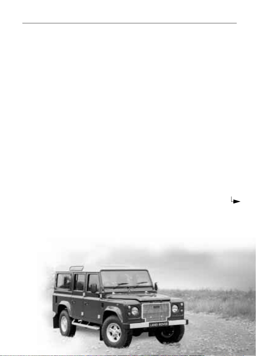
Owner’s Handbook
This handbook covers current Land Rover Defender model s and, together with the Servic e
Portfoli o book, prov ides al l the inf ormation you need to de rive ma ximum ple asure from owning
and dr iving yo u r new vehicle.
For your con venience, the handbook is divided into sections, each dealing with a different
aspect o f the vehicle. These ar e listed on the title page and you wil l find it wo rthwhile to take a
little time to read each one, and get to know your Defender as soon as you possibly can. The
more you under stand befo re you driv e, the grea te r the sat isfa ct ion onc e you ar e se ated beh in d
the steer ing wheel.
IMPORTANT
The speci fication of each vehicle will vary acco rding to territorial requirements and also from
model to model within the vehicle range. Some of the information published i n this handbook,
theref ore, may not ap ply to your part icular veh icle.
Land Rover operates a policy of constant product improvement and therefore reserves the right to change specificati on s
without notice at any time. Whilst every effort is made to ensure complete accuracy of the information in this handbook,
no liabilities for inaccuracies or the consequences thereof can be accepted by the manufacturer or the dealer, except in
respect of personal injury caused by the negligence of the manufacturer or the dealer.
2
Page 3

Contents
Controls & Instruments
Controls . . . . . . . . . . . . . . . . . . . . . . . . . . .9
Locks & Alarm . . . . . . . . . . . . . . . . . . . . .11
Seats . . . . . . . . . . . . . . . . . . . . . . . . . . . . .20
Seat Belts . . . . . . . . . . . . . . . . . . . . . . . . .27
Child Restraints . . . . . . . . . . . . . . . . . . . .30
Door Mirrors . . . . . . . . . . . . . . . . . . . . . . .31
Instruments . . . . . . . . . . . . . . . . . . . . . . .32
Warning Lights . . . . . . . . . . . . . . . . . . . . .33
Lights & Indicators . . . . . . . . . . . . . . . . . . 36
Wipers & Washers . . . . . . . . . . . . . . . . . .39
Horn . . . . . . . . . . . . . . . . . . . . . . . . . . . . .41
Manual Windows . . . . . . . . . . . . . . . . . . . 42
Electric Windows . . . . . . . . . . . . . . . . . . .43
Sunroof . . . . . . . . . . . . . . . . . . . . . . . . . . .44
Heating & Ventilation . . . . . . . . . . . . . . . .45
Air Conditioning . . . . . . . . . . . . . . . . . . . .48
Heated Screens . . . . . . . . . . . . . . . . . . . . .50
Interior Equipment . . . . . . . . . . . . . . . . . .51
Side & Rear Step . . . . . . . . . . . . . . . . . . .54
In-Car Telephones . . . . . . . . . . . . . . . . . .55
In-Car Entertainment . . . . . . . . . . . . . . . .56
Driving & Operating
Starting & Driving . . . . . . . . . . . . . . . . . . .59
Catalytic Converter . . . . . . . . . . . . . . . . . .64
Fuel Filling . . . . . . . . . . . . . . . . . . . . . . . .65
Manual Gearbox . . . . . . . . . . . . . . . . . . . .69
Transfer Gearbox . . . . . . . . . . . . . . . . . . .70
Brakes . . . . . . . . . . . . . . . . . . . . . . . . . . . .73
Traction Control . . . . . . . . . . . . . . . . . . . .76
Towing . . . . . . . . . . . . . . . . . . . . . . . . . . .77
Load Carrying . . . . . . . . . . . . . . . . . . . . . .79
Ancillary Equipment . . . . . . . . . . . . . . . . .80
Engine Oil . . . . . . . . . . . . . . . . . . . . . . . .104
Cooling System . . . . . . . . . . . . . . . . . . . .105
Fuel System . . . . . . . . . . . . . . . . . . . . . .107
Brakes . . . . . . . . . . . . . . . . . . . . . . . . . . .108
Clutch . . . . . . . . . . . . . . . . . . . . . . . . . . .109
Power Steering . . . . . . . . . . . . . . . . . . . .110
Washers . . . . . . . . . . . . . . . . . . . . . . . . .111
Wiper Blades . . . . . . . . . . . . . . . . . . . . . .113
Battery . . . . . . . . . . . . . . . . . . . . . . . . . .114
Tyres . . . . . . . . . . . . . . . . . . . . . . . . . . . .117
Cleaning & vehicle care . . . . . . . . . . . . . .120
Identification Numbers . . . . . . . . . . . . . .123
Parts & Accessories . . . . . . . . . . . . . . . .124
Emergency Information
Wheel Changing . . . . . . . . . . . . . . . . . . .129
Emergency Starting . . . . . . . . . . . . . . . .137
Vehicle Recovery . . . . . . . . . . . . . . . . . .139
Fuses . . . . . . . . . . . . . . . . . . . . . . . . . . .141
Bulb Replacement . . . . . . . . . . . . . . . . . .145
Technical Data
Technical Data . . . . . . . . . . . . . . . . . . . .151
Appendices
Appendices . . . . . . . . . . . . . . . . . . . . . . . . . I
Off-road Driving
Off-road Driving . . . . . . . . . . . . . . . . . . . .85
Driving Techniques . . . . . . . . . . . . . . . . . .89
Owner Maintenance
Maintenance . . . . . . . . . . . . . . . . . . . . . . .97
Bonnet Opening . . . . . . . . . . . . . . . . . . .101
Engine Compartment . . . . . . . . . . . . . . .102
Page 4

Introduction
Introduction
BEFORE YOU DRIVE
WARNING
Your vehicle has a higher ground clearance
and, hence, a higher centre of gravity than
ordinary p assenger cars. This will resu lt in
different handling characteristics.
Inexperienced drivers should take additional
care, particularly in off-road driving
situations and when performing abrupt
manoeuvres on unstable surfaces.
SYMBOLS USED
The following symbols used within the
handbook call y our a ttention to s pecifi c ty pes of
information.
This recycling symbol identifies t hose
items that must be disposed of safely in
order to pre vent unnecess ary damage to the
environment.
*An asterisk appearing wi thin the text,
identifies features or items of equipment that
are either optional, or ar e only fitted to some
vehicles in the model range.
WARNIN GS IN THI S HA NDBOOK
WARNING
Safety warn ings are included in this
handbook. Th ese indicate either a procedure
which must be foll owed precisely, or
information that should be con sidered with
great care in order to avoid the possibility of
personal injury or serious damage to the
vehicle.
SECURITY CARD
The security card, sup plied with t h e literature
pack, contains important emergency
information. It is ESSENTIAL that you keep the
card saf e from th eft an d ensure th at it is pass ed
to the new owner if you sell the vehic le.
• Key number: This is the number of the
starte r/doo r key - essent ial if you ever nee d
to obta in a re placem en t.
• Emergency k ey access cod e: You wil l nee d
this code in order to start the vehicle if the
handset has been lost or dama ged (see
‘Emergency key acces s’, page 15).
• Locking whee l nut number: If your vehicle
has locking wheel nuts, you will have been
provided with a special wheel nut socket to
remove the m. You will need to quot e this
number to obtain a replacement socket.
• VIN (vehicle identification number): This
identity number is unique to your veh icle
and is essential proof of i ts specificat ion.
The number can also be found in various
locations around the vehicle (see ‘VEHICLE
IDENTIFICATI ON NUMBER (VIN)’,
page 123).
• Radio securit y code numbe r
code must be entered into the radio
whenever the power suppl y has been
disconnected. Without this code, the radio
unit will not operate (see 'Securit y co d e' in
the 'In-Car Entertain m en t' book).
*: This unique
WARNING
Never leave th e se c urity card insid e th e
vehicle when it is unattended.
Memorise t he emerge ncy key access cod e, or
keep the card on yo ur pers on while dri ving, in
case of emergencies.
4
Page 5
Introduction
T
N
T
I
S
SERVICE PORTFOLIO
The Service Portfolio book included in your
literature pack contai ns important vehicle
identifi cation information, details of your
entitlement under the terms of the Land Rover
warrant y, as well as useful consumer advice.
Most im p ortant of all, however, is th e se c t io n
on maintenance. This outlines the servicing
requirem ents for your v ehicle a nd also i nclude s
the First Service Voucher, and the service
record slips, which th e Dealer shoul d sign and
stamp to certify that the routine services have
been car rie d o ut at the r eco mmend ed inte rv al s.
WARNING LABELS ATTACHED TO THE
VEHICLE
Warning lab els at tached t o your v ehicle
bearing this symbol mean: DO NOT
touch or ad just component s until you
have read the relevant inst ructions in
the handb ook.
Warning labels showing this symbol
indicate that the igni tion system uti lises
very high voltages. DO NOT touc h any
ignition components while th e starter
switch is turned on!
DIFFERENTIAL LOCK LABEL
THE DIFFERENTIAL LOCK SHOULD ONLY BE ENGAGED WHEN TRACTION IS LIKELY
WIDE THROTTLE OPENINGS SHOULD BE AVOIDED WHEN USED IN CONJUNCTION WI
1st AND 2nd GEAR LOW RANGE. AS SOON AS THE DIFFICULT SURFACE HAS BEE
DIFFERENTIAL LOCK MUST BE RELEASED.
A SINGLE AXLE ROLLER RIG MAY BE USED FOR SPEEDS UP TO 5km/h. THE CEN
DIFFERENTIAL LOCK MUST BE DISENGAGED. FOR ROLLER TESTS OVER 5 km/H E
WHEELS MUST BE ROTATED AT THE SAME SPEED OR IF ONLY A SINGLE AXLE ROL
AVAILABLE, THE CENTRE DIFFERENTIAL MUST BE LOCKED AND THE PROPELLER
STATIONARY AXLE MUST BE REMOVED.
H3757
Informa tion concerning operation of the
differential lock is printed on the centre
console. This is important information and
must be under stood fully wit h reference to the
‘Gearbox and Transmission’ sections of this
handbook , before using the transfer gearbox.
The label contains the following warning:
“THE DIFFERENTIAL LOCK SHOULD ONLY BE
ENGAGED WHEN TRACTION IS LIKELY TO BE
LOST. WIDE THROTTLE OPENINGS SHOULD
BE AVOIDED WHEN USED IN CONJUNCTION
WITH 1st AND 2nd GEAR LOW RANGE. AS
SOON AS THE DIFF ICUL T SURFAC E HA S BE EN
CROSSED THE DIFFE RENTI AL LOCK M UST BE
RELEASED.
A SINGLE AXLE ROLLER RIG MAY BE USED
FOR SPEEDS UP TO 5 km/h. THE CENTRE
DIFFERENTIAL LOCK MUST BE DISENGAGED.
FOR ROLLER TESTS ABO VE 5 km /h EITHER
ALL FOUR WHEELS MUST BE ROTATED AT
THE SAME S PEED OR IF ONL Y A SI NGLE AXLE
ROLLER RIG IS AVAILABLE, THE
DIFFERENTIAL MUST BE LOCKED AND THE
PROPELLER SHAFT TO STATIONARY AXLE
MUST BE REMOVED.”
WARNING
5
Page 6

Introduction
IN AN EMERGENCY
IMPORTANT INFORMATION
Remember the breakdown safety code
If a brea k down oc cu rs wh ile trav el li n g :
• Wherever possible, consistent with
road safet y and traffi c condition s, the
vehicle should be moved off the main
thoroughfar e, p refe rab ly i nt o a la y-by. I f
a breakdown oc curs on a motorway,
pull well ove r to the inside of the hard
shoulder.
• Switch on hazard lights.
• If possible, position a warning triangl e
or a flashing amber light at an
appropriat e dist ance from the vehicl e to
warn other traffic of the breakdown,
(note the legal requirements of some
countries).
• Evacuate passengers through nearside
doors onto the verge, well away from
the road, as a precaution in case your
vehicle is accidenta lly struck by other
traffic.
6
Page 7
Controls & Instruments
Controls
CONTROLS . . . . . . . . . . . . . . . . . . . . . . . . . . . . . . 9
FASCIA SWITCHES . . . . . . . . . . . . . . . . . . . . . . . 10
Locks & Alarm
KEYS AND HANDSETS. . . . . . . . . . . . . . . . . . . . . 11
ALARM SYSTEM . . . . . . . . . . . . . . . . . . . . . . . . . 11
INTERIOR SPACE PROTECTION . . . . . . . . . . . . . 14
ENGINE IMMOBILISATION . . . . . . . . . . . . . . . . . 15
REMOTE HANDSET BATTERY . . . . . . . . . . . . . . . 16
ALARM OR HANDSET DIFFICULTIES. . . . . . . . . . 18
CHILD-PROOF LOCKS . . . . . . . . . . . . . . . . . . . . . 19
TAIL DOORS . . . . . . . . . . . . . . . . . . . . . . . . . . . . 19
Seats
FRONT SEATS . . . . . . . . . . . . . . . . . . . . . . . . . . . 20
HEAD RESTRAINTS . . . . . . . . . . . . . . . . . . . . . . . 21
HEATED FRONT SEATS . . . . . . . . . . . . . . . . . . . . 22
FOLDING THE REAR SEATS. . . . . . . . . . . . . . . . . 23
Seat Belts
SEAT BELT SAFETY . . . . . . . . . . . . . . . . . . . . . . . 27
SEAT BELTS. . . . . . . . . . . . . . . . . . . . . . . . . . . . . 28
CARING FOR SEAT BELTS. . . . . . . . . . . . . . . . . . 29
Child Restraints
CHILD SEATS. . . . . . . . . . . . . . . . . . . . . . . . . . . . 30
Page 8

Door Mirrors
EXTERIOR MIRRORS . . . . . . . . . . . . . . . . . . . . . 31
Instruments
INSTRUMENT PANEL . . . . . . . . . . . . . . . . . . . . . 32
Warning Lights
WARNING LIGHTS . . . . . . . . . . . . . . . . . . . . . . . 33
Lights & Indica tors
DIRECTION INDICATORS . . . . . . . . . . . . . . . . . . 36
LIGHTS . . . . . . . . . . . . . . . . . . . . . . . . . . . . . . . . 36
FOG LIGHTS . . . . . . . . . . . . . . . . . . . . . . . . . . . . 38
HAZARD WARNING LIGHTS. . . . . . . . . . . . . . . . 38
Wipers & Washers
OPERATING . . . . . . . . . . . . . . . . . . . . . . . . . . . . 39
WINDSCREEN WIPERS . . . . . . . . . . . . . . . . . . . 39
WINDSCREEN WASHER . . . . . . . . . . . . . . . . . . . 40
REAR WINDOW WIPER AN D WA SHE R . . . . . . . 40
Horn
HORN . . . . . . . . . . . . . . . . . . . . . . . . . . . . . . . . . 41
Manual Windows
FRONT AND REAR WINDOWS . . . . . . . . . . . . . . 42
SLIDING REAR WINDOWS . . . . . . . . . . . . . . . . . 42
Electric Wind ows
ELECTRIC WINDOWS. . . . . . . . . . . . . . . . . . . . . 43
Interior Equipment
INTERIOR LIGHTS . . . . . . . . . . . . . . . . . . . . . . . 51
CLOCK . . . . . . . . . . . . . . . . . . . . . . . . . . . . . . . . 51
CIGAR LIGHTER . . . . . . . . . . . . . . . . . . . . . . . . . 52
ASHTRAY . . . . . . . . . . . . . . . . . . . . . . . . . . . . . . 52
CUBBY BOX . . . . . . . . . . . . . . . . . . . . . . . . . . . . 53
INTERIOR REAR-VIEW MIRROR . . . . . . . . . . . . 53
Side & Rear Step
STEPS. . . . . . . . . . . . . . . . . . . . . . . . . . . . . . . . . 54
In-Car Telephones
IN-CAR TELEPHONES. . . . . . . . . . . . . . . . . . . . . 55
In-Car Entertainment
RADIO AERIAL . . . . . . . . . . . . . . . . . . . . . . . . . . 56
IN-CAR ENTERTAINMENT . . . . . . . . . . . . . . . . . 56
Sunroof
SUNROOF. . . . . . . . . . . . . . . . . . . . . . . . . . . . . . 44
Heating & Ventilation
VENTILATION . . . . . . . . . . . . . . . . . . . . . . . . . . . 45
HEATER CONTROLS. . . . . . . . . . . . . . . . . . . . . . 46
USING YOUR HEATER . . . . . . . . . . . . . . . . . . . . 47
Air Conditioning
AIR CONDITIONING CONTROLS. . . . . . . . . . . . . 48
USING THE AIR CONDITIONING. . . . . . . . . . . . . 49
Heated Screens
HEATED FRONT SC RE E N AND RE AR WIND OW . 50
8
Page 9
Controls &Ins truments
Controls
CONTROLS
Controls
11
6
9
7
12
39
6
8
100
80
km/h
60
40
20
0
-
D
N
A
L
O
R
-
V
E
R
16
14
15
12
H3748
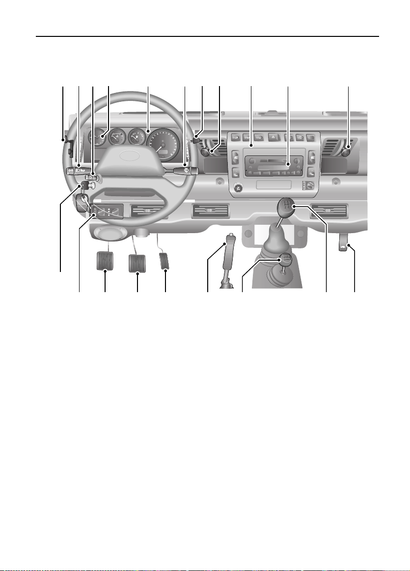
1. Fresh ai r vent control
2. Audio system
3. Fascia swi tches (see ov erleaf)
4. Fresh ai r vent control
5. Air blower control
6. Direction indicators and horn cont rol
7. Lighting swi tch
8. Instrument panel
9. Clock
10. Windscreen wiper /washer control
13
5
10
120
140
160
180
200
1
18
19
3
2
20
4
17
11. Air temperature & dist ribution controls
12. Air conditioning controls
*
13. Accelerator pedal
14. Brak e pedal
15. Clutch pedal
16. Star ter switch
17. Bonnet release lever
18. Handbrake
19. Transfer gear lever
20. Main gear lever
NOTE: The precise specification and location o f the control s may vary according to territorial
requirem ents and from model to m odel within the vehicle rang e.
9
Page 10
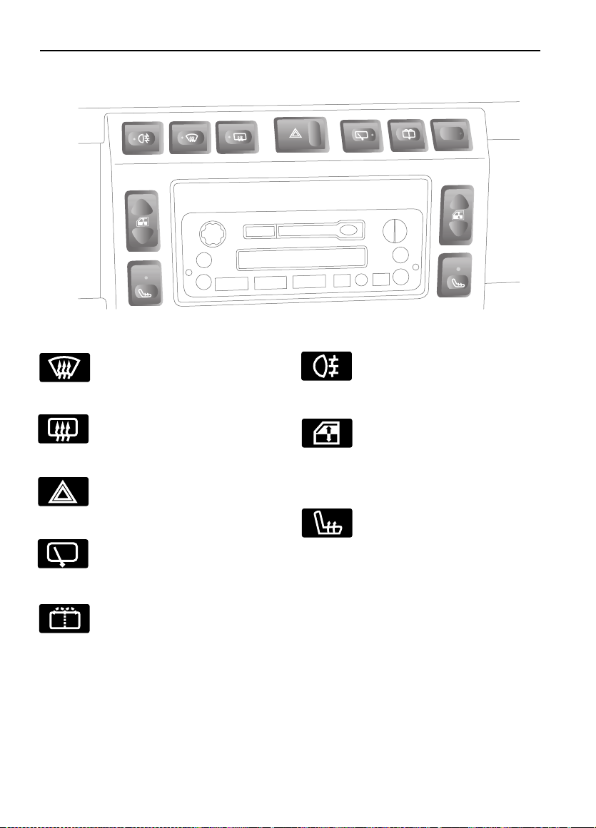
FAS C IA SWITCHES
H3667
Controls
Heated front screen*
Press to operate (see ‘Heated front
screen*’, page 50).
Heated rear screen
Hazard warning lights
Rear window wiper
Rear window washer
*
Press to operate (see ‘Heated rear
window*’, page50).
Press to op erate (see ‘HAZARD
WARNING LIGHTS’, page 38).
*
Press to op erate (see ‘Rear
window wiper’, page 40).
Press to op erate (see ‘Rear
window washer’, pag e 40).
Rear fog guard li ghts
Press to operate (see ‘Rea r fog
guard lights’, page 38).
Electric windows
Press the appropriate switch to
operate the front left or right
window (see ‘Oper ating the
windows’, page43)
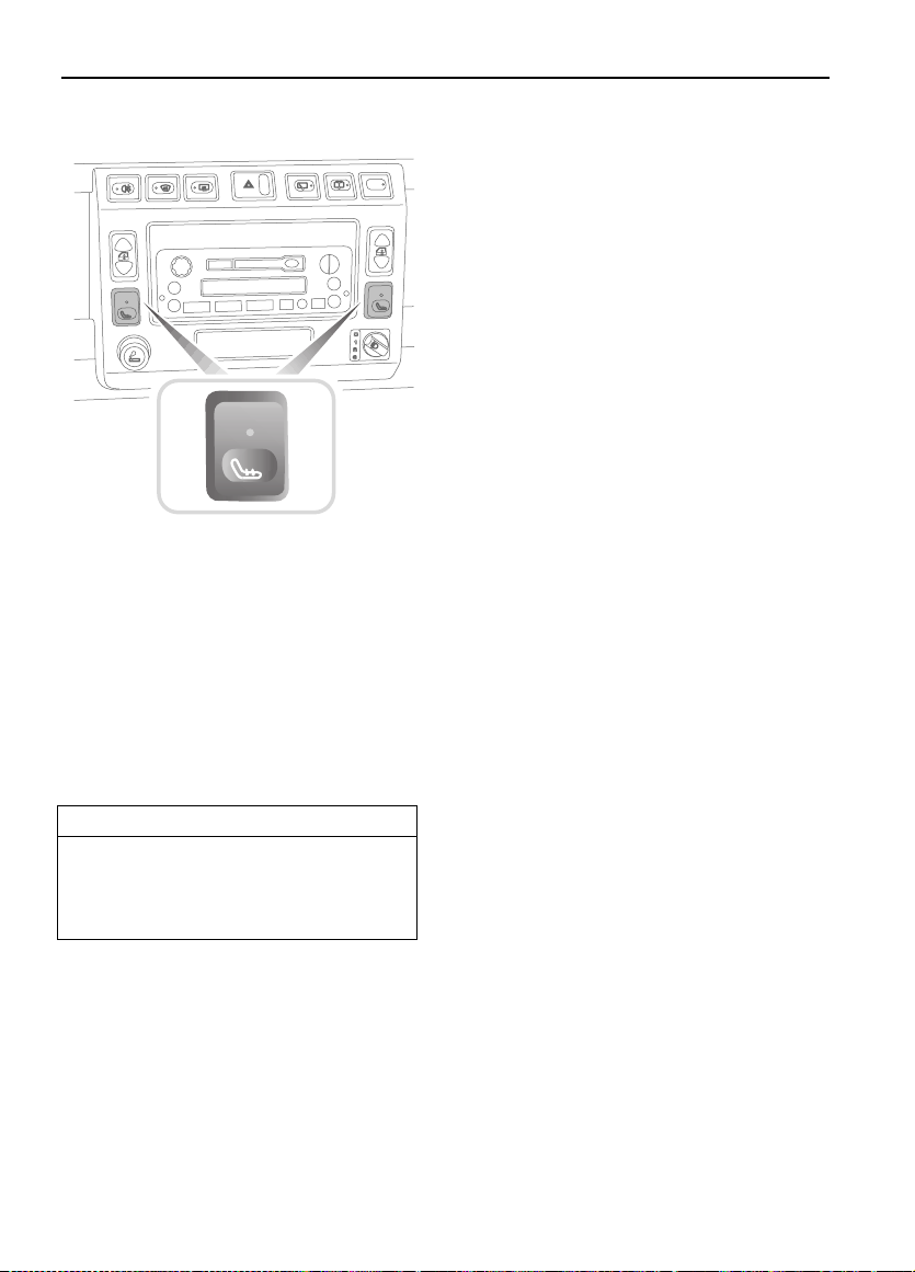
Seat heaters
SEATS*’, page 22).
*
Press the appropriate switch to
operate the front left or r ight seat
heater (see ‘HEATED FRONT
*
*
*
10
Page 11
Locks & Alarm
Locks & Alarm
KEYS AND HANDSETS
You have been supplied with two remote
handsets and two sets of keys , comprising :
• A black key for ope ra ting the starter sw itch
and door locks.
• A smalle r metal key to operate the fuel fill er
cap lock.
The starter key number is stamped on a tag
attache d to the key ring. Check that the key
number has be en ent ered in th e space p rovid ed
on your Security card.
If the remote handset is lost, contact a Land
Rover dealer, who can supply a replacem ent
unit.
WARNING
Keep the Securi ty car d and spare h andset and
keys in a safe place - NOT IN THE VEHICLE!
ALARM SYSTEM*
Your vehicle is fitted with a sophisticated
electronic anti- theft alarm an d engine
immobili sation system . In order to ensure
maximum secur it y and ope rat ing co nve ni ence,
you ar e st rongly ad vised to ga in a full
understanding of the alarm system, by
thoroughly reading this section of the
handbook.
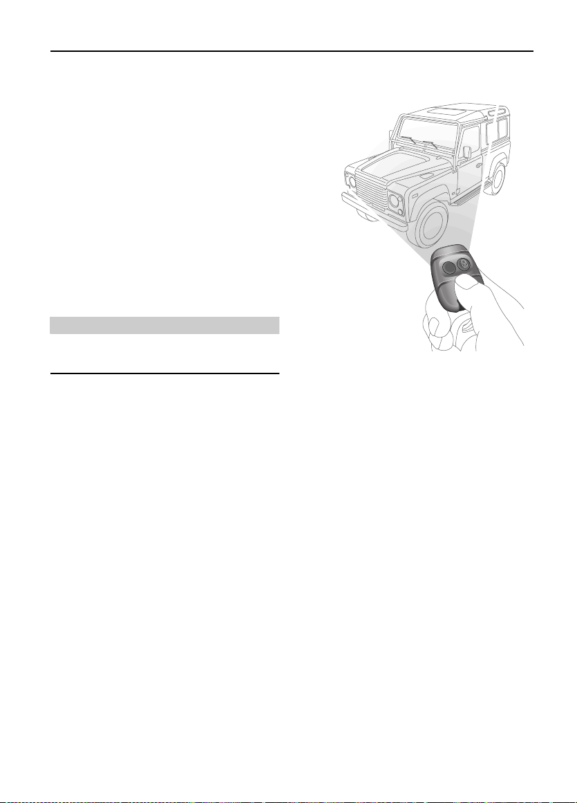
Using the remote handset
H3619
While it i s not ne ces sary to po int the h andset a t
the veh icle, the h andset must b e wit hin rang e of
the vehicl e when a but to n is press ed. Note that
the oper ating range may va ry depending up on
handset battery condition and may sometimes
be limite d by physi ca l and g eog ra phica l f acto rs
beyond your control. From a security point of
view, i t m ay not be wise to unl ock unless you
are within a few feet of the vehicl e.
Vehicles with central door locking
Locking with the remote handset:
Press th e lock (padloc k symbol) button once:
• all doors are locked (including the tail door )
• engine immobilised
• perimetric alarm activated (protects the
doors and bo nnet)
• interior space protection activated
The dire ction indicator lights flash three times
to confirm that the vehicle is secure and the
anti-theft alarm indicato r light (in the
instru m ent panel) st arts to flas h.
11
Page 12

Locks & Alarm
Locking with th e key:
Insert the key and turn the driver’s door lock
towards the rear of the vehicle:
• all doors locked (including the tail door)
• engine immobilised
• NO PERIMETRIC ALARM OR INTERIOR
SPACE PROTECTION
The anti-theft alarm indicator light (in the
instrument panel) start s to flash after 30
seconds to show that the engine is
immobilised.
Unloc ki n g w ith th e re mo te ha nd s e t:
Press the unlock (PLAIN) button once to
disarm the alarm and unlock the doors.
The directi on indica tor lig hts flas h once an d the
interior lights illuminate.
Unloc ki n g w ith th e ke y :
While all the doors can be unlocked using the
key in the d river’s doo r lock, this method is NOT
RECOMMENDED - dependin g on the
specification of the vehicle the alarm may not
be disarmed.
Vehicles without central door locking
Locking & unlocking:
Each door lock m ust be operated individuall y,
using the key. The han dset wi ll NOT oper ate th e
door locks. Turn t he k ey to war ds the r ea r of t he
vehicle to lock and towards the front to unlock.
Arming & disarming the alarm:
Press the lock button on the hands et to arm the
alarm.
• Perimetric protection protects the doors
and bonnet.
• Interior space protection is activated.
• Engine is immobilised.
Provided the doors and bonnet are securely
closed, the direction indicators will flash three
times and the anti-theft alarm indicator in the
instru ment panel will start to flash.
To disarm the alarm, press th e unlock (PLAIN)
button on the handset; the direction indicators
will flash once and the interior lights i lluminate .
Door sill loc king buttons
From insi de the vehicle , each door can be
individually locked by depressing the
appropri ate sill locking button.
H3664
WARNING
DO NOT depre ss the si ll bu ttons a s a means of
locking the doors from outside the vehicle
(this practice - known as ‘slam locking’ - is
NOT recommended, because key s can be
locked in side accidentally).
On vehicles w ith central door locking, operation
of the driver’s door sill locki ng button locks all
the other doors too. However, engine
immobili sation and interior space protection
are suspended unless the handset lock button
is presse d as well.
12
Page 13
Locks & Alarm
20
40
60
80
100
120
140
160
180
200
2
NOTE: Slam locking, as described abov e, is
prohibited on vehicles with central door
locking.
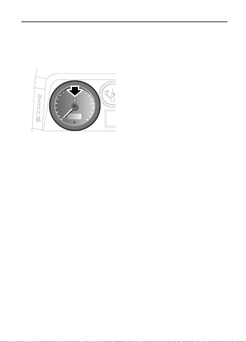
Anti-thef t alarm indicator light
100
120
80
60
40
20
0
H3662
140
160
180
200
The indica tor l ight i n the sp eedom eter ( arrowed
in illustration) provides information about the
status of the alarm system, as follows:
When the alarm i s armed:
The light fl ashes rapidly whi le the alarm is
arming it self. After ten seconds, the light
adjusts to a slower frequency and continues to
flash as an anti-the ft det erren t until th e alarm is
disarmed.
If the engine is imm obilised (even tho ugh the
alarm has been disarmed ):
The light flashes slowly until the engine is
remobilised.
If the alarm has been triggered :
The light will flash rapi dly when the alarm is
disar med until the starter switc h is turned to
position I I.
Mislock
If a door is not fully closed when the handset
lock button is pressed, t he hazard warning
lights will fail to flash, indicating a mislock. In
this case, the alarm system will not be fully
armed and on vehicles with central door
locking, none of the doors will lock.
As soon as t h e op e n ap e r t ur e i s clo se d, the
hazard warning lights will flash and the
anti-theft alarm indica tor light will resume
flashing to confirm that the system has
return ed to a fully arm ed state.
NOTE: If a misloc k occur s as a result of an op en
door, interior space pr otection will not be
activated.
NOTE: If a misl ock oc curs a s a resul t of a n open
bonnet, th e door apertur es will sti ll be protected
by the alarm system and interior space
protection will be active.
If the alarm sounds
If the alarm is triggered, the alarm sounder or
vehicle horn will sound for 30 seconds before
switching off and resetting itself to the sam e
protecti on s tatu s t hat ex is ted pr i or to t he al arm
being triggered. The alarm can be triggered up
to three times befo re needing to be reset.
To silenc e t he a larm , pr es s eit her bu tton o n t he
remote handset.
NOTE: While the alarm is sounding, the hazard
warning lights will flash to provide a visual
alarm.
If the remote handset battery power is low:
The light will flash rapidly during the initial ten
seconds af ter the handset has bee n used, wh ile
the alar m system is arming.
If the driver’s door is open:
The light illuminates fo r ten seconds, before
adjustin g to slow frequency flashing.
13
Page 14
Locks & Alarm
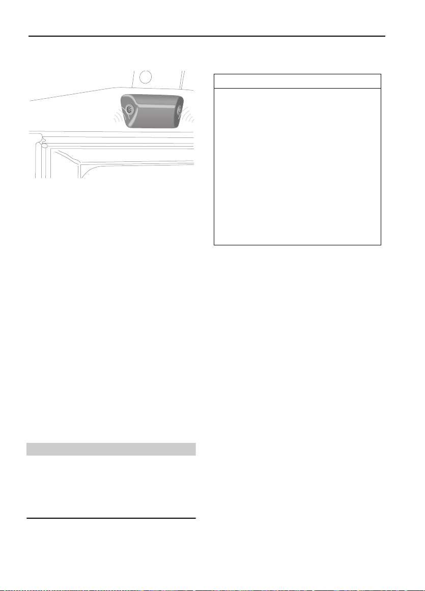
INTERIOR SPACE PROTECTION*
Interior s pac e prote ct ion i s des igned to pr otect
the interior of the vehicl e from intr u sion (entry
by a thief thro ugh a smashed window, for
example). Twin sensor s monitor the interior
space and ac tiva te the ala rm if ai r movemen t i s
detecte d in the passenge r compartment.
Using the handset:
Interior space protection is activated
automatically when ever the remote handset is
used to set the alarm and can ONLY be
deactivat ed with the handset.
Key operation:
On vehicles fi tted with central door locki ng,
using the key t o arm the alarm wi ll NOT act ivate
(or deactivate) interior space prot ection.
NOTE: Interior space protection cannot be
activated if a door is open, or if the sta rter
switch is turned on.
Vehicles without central door locking
IMPORTANT INFORMATION
To disable interior space protection when
settin g the alarm, use the following
procedure:
1. Open the driver’s door.
2. With the driver’s door open, us e th e
handset to arm the alarm in the
normal way.
3. Clos e th e dr i v e r’s door (the hazard
warning lights flash three times and
the anti-theft in dicator light
commence s flashing ra pidly).
The alarm system is now armed with
interior pr otect io n disabl e d.
NOTE: Interi or protection will not operat e for
the first 15 seconds after the alarm is set.
WARNING
Never activate interior space protection if
windows or sunroof are to be left open, or if
passengers or animals are to be left inside
the vehicle - any movement will activate the
alarm.
14
Page 15
Locks & Alarm
ENGINE IMMOBILISATION
Engine immob ilisati on is an importan t aspect of
the secur ity system, and includes a fe ature
known as ‘passive immo b ili sa ti on ’. This is
designed to safeguard the vehicle from theft,
should th e driver forg et to lock the do ors or arm
the alarm. Engine immob ilisation i s automatic
whenever an y of the following conditions
occur:
• The vehicle is locked using handset or key.
• Thirt y se c on d s after the st arter swi tch has
been turned off AND the driver 's door
opened.
• Five minutes af ter the star ter switc h is
turned of f, o r the ala rm sy ste m is di sa rmed .
IMPORTANT INFORMATION
The engine immobilisation system relies
on the hands et to re-mobil ise the engin e.
Look after the handse ts at all time s,
protecting them from loss, damage and
battery discharge.
If the engine has immobilised passively,
re-mobil isation will occur when the starter
switch is turned to position ‘II’, provided
the handset is on the same ring as the key
and in close proximity to the switch.
• ALWA YS keep the handset on the same
ring as the key.
• NEVER attach both handsets to th e
SAME key ring.
Any attempt to start the engine while it is
immobilised, will cause the engine
immobilisation warning light (in the
speedometer) to flash.
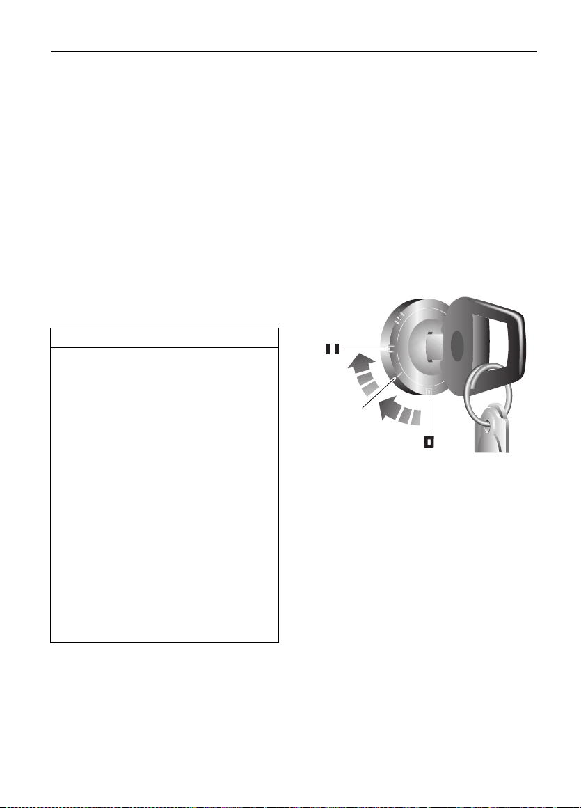
Emergency key access
If the handset is damaged , or fails to operate,
the engine can be re-mobilised by using the
starte r ke y to en ter a uniqu e four num b e r
emergency key access code. The code is
record ed o n the Sec uri ty c ar d an d is ent ered as
follows:
If your handset is lost or inoperative, it is
impossi ble t o disar m th e al ar m. As soon as t he
door is opened, the alarm wil l sound
(continuously for up to three 30 second
periods), and continue while the code is being
entered.
H3615
1. Remove the ha ndset fr om the k ey ring a nd
keep the handset well away from the
starter switch when entering the code.
2. From inside the vehicle, with the driver’s
door clo sed, immediately insert the key
into the star ter switc h and turn to posit ion
‘II’. Hold t his position unt il the alarm
sounds, then switch off and open and
close th e driver’s door.
3. Turn the star ter switch to position ‘II’ the
required number of times to enter the first
digit of the code (if the first digit is 4, turn
the key to positi on ‘II’ and th en ba ck to ‘0’
four times).
4. Open and close th e drive r’s do or (t his wi ll
enter the first digit of the code).
15
Page 16

Locks & Alarm
5. Turn the starter swi tch to positi on ‘II’ an d
back to ‘0’ the r equi red numb er of ti mes to
enter the SECOND digit of the code.
6. Open and cl ose the driver’s door again.
7. Turn the starter swi tch to positi on ‘II’ an d
back to ‘0’ the r equi red numb er of ti mes to
enter the THIRD digit of the code.
8. Open and cl ose the driver’s door again.
9. Turn the starter swi tch to positi on ‘II’ an d
back to ‘0’ the r equi red numb er of ti mes to
enter the FOURTH digit of the code.
10. Finally, open and close the driver’s door
one more time.
If the co d e h as be en entered co rrectly, the
anti-theft indicator light will extinguish, the
alarm will s top so undi ng and th e en gi ne can be
started.
If an incorrect code has been entered:
If the code is entered incorrectly, the alarm
sounder will sound twice, th e anti-theft
indicator light will continue to illuminate, and
the eng i n e will fail to star t. B ef or e en tering th e
code again, turn the starter switch to position
‘II’ and hold in this position for 5 seconds.
After thr ee failed en try attempts, the security
system in vokes a del ay pe ri od of th irty mi nut es
during whic h the system wi ll not accep t any
further attem p ts to en te r a co d e.
IMPORTANT INFORMATION
Memorise the emergency key access code
or keep t he Sec uri t y car d on yo ur person i n
case of emerge ncies. NEVER leave the card
in the vehicle.
REMOTE HANDSET BATTERY
The battery should last for approximately
three yea rs dependent up on use. When the
battery ne eds repl aci ng it wi ll be appar ent from
the following s ymptoms:
• The handset will only work every other
operation while disarming.
• The hazard warning lights will not flash
when th e alarm is disarme d .
Always fit a La nd Rover STC 4080 or a
Panasoni c CR2032 replacement battery
(available from a Land Rover dealer).
IMPORTANT INFORMATION
• DO NOT remove a bat tery until you are
ready to install the replacement.
• The engin e will immob ili se f ive mi nut es
after t he key is removed from the
starte r sw itch (or 30 se conds after the
starte r has been switched off and the
driver’s door opened). If handset
battery re placement is NO T com p leted
within this period, the emergency key
access code will have to be entered
before the handset can be
synchronised.
WARNING
The handset contains delicate electronic
circuits and must be protected from impa ct
and water damag e, high temperatures and
humidity, direct sunlight and the effects of
solvents, waxes and abrasive cleaners.
16
Page 17
Locks & Alarm
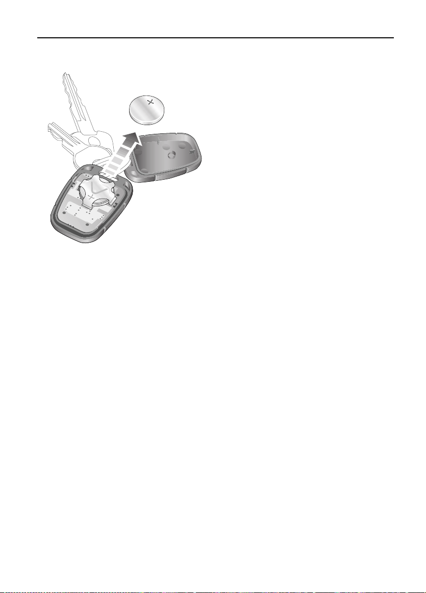
Battery replacement
H3663
1. Unlock the vehicle and disarm the alarm
system.
2. Turn the s tart er swit ch to posit ion ‘II’, then
turn to position ‘0’ and remove the key.
3. Carefully prise the handset apart ; start
from the key rin g end u sing a co in or sm all
screwdriver. Avoid da m aging the seal
between the two halves o f th e case a nd DO
NOT allow dirt or moisture to get inside
the handset.
4. Slide the bat tery out of i ts cl ip , ta king c ar e
to avoid touching the circuit board or the
contact surfaces of the clip.
5. Press and hold one of the buttons for at
least five seconds (t his will drain any
residual power from the ha ndset).
6. Fit the new battery, ensuring that correct
polarity is maintained (‘+’ side fa cing up).
Finger marks will adversely affect battery
life; if possible, avoid touching the flat
surfaces of the battery and wipe them
clean before fitting.
7. Press the tw o hal ves of th e ha nds et fir mly
togeth er and ensure that both halves are
fully joined, to prevent dirt or moisture
from ente ring the hands et.
8. Operate th e PA D L O C K symbo l bu t t on at
least four times within range of the vehicle
to resynchronise the handset.
9. Press the unlock button once to unlock the
vehicle.
The handset is now ready for use.
17
Page 18

Locks & Alarm
ALARM OR HAND S ET DI FF ICU L TIE S
If the alarm goes off unexpectedly:
Ensure all t he wi ndow s a nd sun roo f are c lo sed,
or if they need to be left open, disable interior
space protection.
If the alarm goes off when a door is opened:
Disarm the al arm with the handset befor e
unlocking. If the handset has failed, enter the
emergency key access cod e (refer to
‘Emergency key access’, page15).
If the starter will not operate:
Ensure the handset is on the same key ring as
the starter key. If it still will not operate, consult
a Land Rover dealer.
If the hazard warning lights fai l to flash when
the alarm is armed:
A door or bonnet is partiall y opened - close the
open aperture and try again.
IMPORTANT INFORMATION
Battery disconnection
Your vehicle is equipped with a batt ery
backed-up sounder, which operates as an
anti-theft siren if the vehicle battery is
disconnected.
Before disconnecting the vehicle battery, it
is ESSENTIAL to re fer to ‘Battery re m o val
and replacement’, page 115, in order to
prevent the alarm from sounding.
If the vehicle battery is disconnected for
any reason, the status of the securi ty
system prior to disconnection will be
memorised and automati cally reset wh en
the batt ery is reconnect ed.
18
Page 19
Locks & Alarm
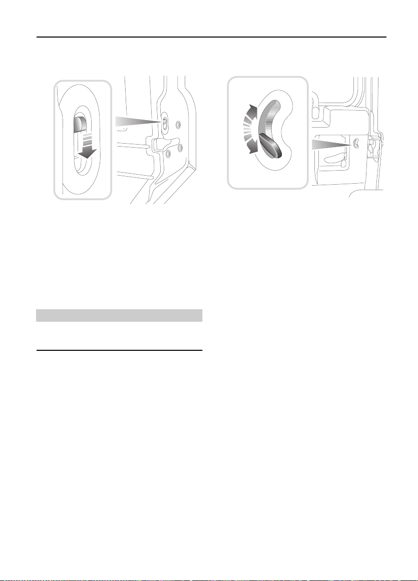
CHILD-PROOF LOCKS *
H3661
Move the l ockin g levers o n the r ear doo rs down
to engage t h e child locks.
With the child-proof locks engage d, the rear
doors cann ot be opened from in side the
vehicle, thereby avoiding the risk of a door
being opened accidentally while the vehicle is
moving.
WARNING
NEVER leave children unsupervised in the
vehicle.
TAIL DOORS *
H3618
From outside, use the key to lock and unlock
the taildoor. From insi de and with the door
closed, push the locking button up to lock and
down to unlock (see illust ration).
19
Page 20
Seats
Seats
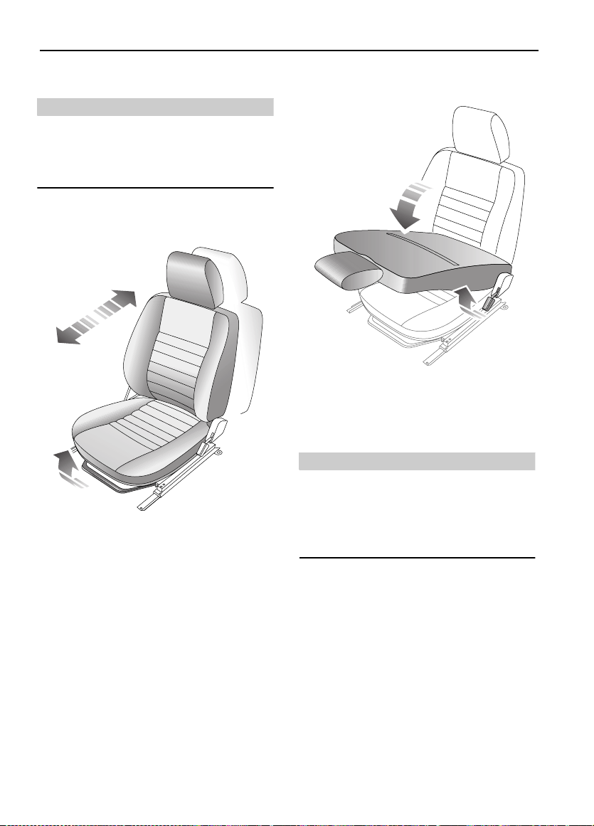
FRONT SEATS
WARNING
To avoid the risk of loss of control and
personal injury, DO NOT adjust the driver's
seat or head restraint while the vehicle is in
motion.
Forward/backward adjustment
H3708
Lift the bar at the front of the seat to slide the
seat for w ard or back. Ensure the seat is locked
in position before driving.
Seat back adjustment
H3707
Lift th e lever on the si de of the seat and lean
backwards or forwards to achieve the desired
angle, t hen lower the lever to lock.
WARNING
DO NOT travel with the seat backs recli ned
steeply rearwards. Optimum benefit is
obtained f rom t he se at bel t wit h the sea t bac k
angle set to approximately 25 degrees from
the upright (vertical).
20
Page 21
Seats
Seat cushion removal
When replacing, inser t the lugs at the back of
the seat cu shion into the correspondi ng holes
where the seat base meet s the seat back, then
push firmly down on the front of the seat
cushion to secure in place.
NOTE: On cars equipped with seat heate rs, an
electrical lead connects the heater unit in the
seat cus hion with the vehicle wiring harness.
When rem oving the seat cushion care must be
taken to avoid straining or damaging the lead.
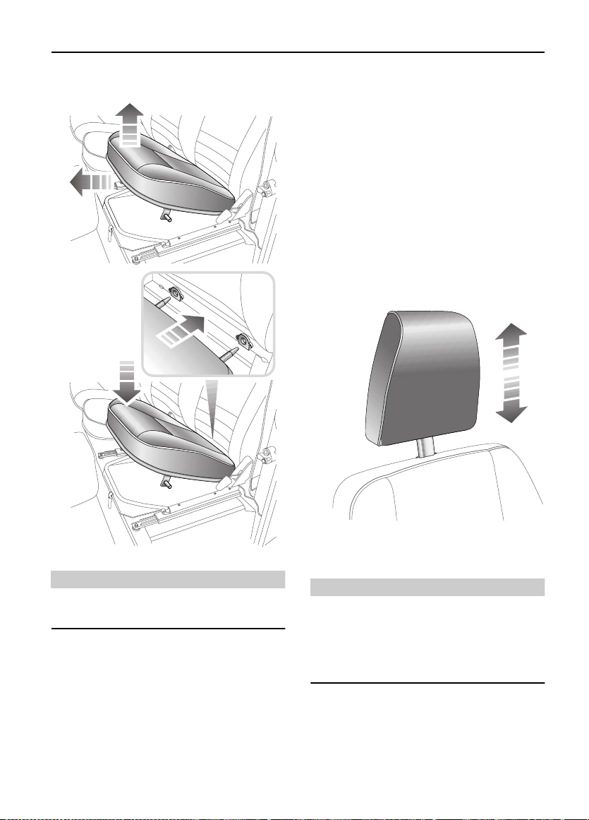
HEAD RESTRAINTS
H3709
WARNING
ENSURE that the seat cushion is securely in
place before driving.
The front seat cushions can be removed to
access the battery and secondary fu se box as
follows:
Pull up the front of the sea t base to rele ase it
from its retaining clips, then pull the cushion
forward to remove.
H3710
Pull the head restraint up or down until the
cushion is level with the back of the head.
WARNING
Head rest raints are designed to support the
back of the head (NOT THE NECK), and to
restrain rearward movement of the head in
the even t of a c olli si on. The re strai nt must be
positione d lev el with the head to be ef fect ive.
21
Page 22
Seats
HEATED FRONT SEATS*
H3670
With the starter switch turned on, press the
switches to operate the heating elem ents in
either the driver's o r front passen ger seat (the
indica to r lig h t in th e switch illumi na te s ). P re ss
a second time to switch off.
The seat heate rs are thermostat ically cont rolled
and operat e intermittently to achieve and then
maintain a pred etermi ned tem peratu re be tween
26° - 36°C.
IMPORTANT INFORMATION
The seat heaters consume considerable
power from the battery. For this reason,
they should ONL Y be operated while the
engine is running.
NOTE: The centre front seat
with heating elements.
* is not equipped
22
Page 23
Seats
FOLDING THE REAR SEATS
WARNING
DO NOT adjust the seats while the vehicl e is
in motion.
When re-er ecti ng t he 60/40 s pl it re ar seats
ensure that the seat stands are properly
positioned.
When the seat is erected, the latching
mechanism should be visually checked and
physically tested to ensure that the latch is
secure before driving.
Before fo lding the rea r seats:
• Slide the front seats forward.
• Ensure tha t the outer re ar seat belts are
correct ly stowed.
• Pass the seat be lt loc ks t hrough the jun ction
of the b ackre st an d the cus hi on and in to th e
loadspace.
*,
60/40 split rear seats
2
3
4
*
1
H3712
1. Pull up the release catch ( see inset).
2. Fold the backrest forward.
3. Lift and fold the seat base forward.
4. Fold away the seat stand.
23
Page 24
Seats
Individually split rear seats
NOTE: The centre seat cannot fold until both
outer seats have been folded.
H3740
*
H3741
Outer seats:
1. Releas e the catch (see first inset).
2. Fold th e backrest for w ard.
3. Slide back the bolt (see second inset).
4. Lift and fold the seat base forwards.
24
Page 25
Seats
Centre seat:
1. Release the catch - as stage ‘1’ for the
outer sea ts.
2. Fold the ba ckrest forward.
3. Lift and fold the seat base forward s .
When returning the backrest to the upright
position , ensur e that bo th the se at base and the
backrest of all thre e seats are securely latched
in place before driving.
H3720
25
Page 26
Seats
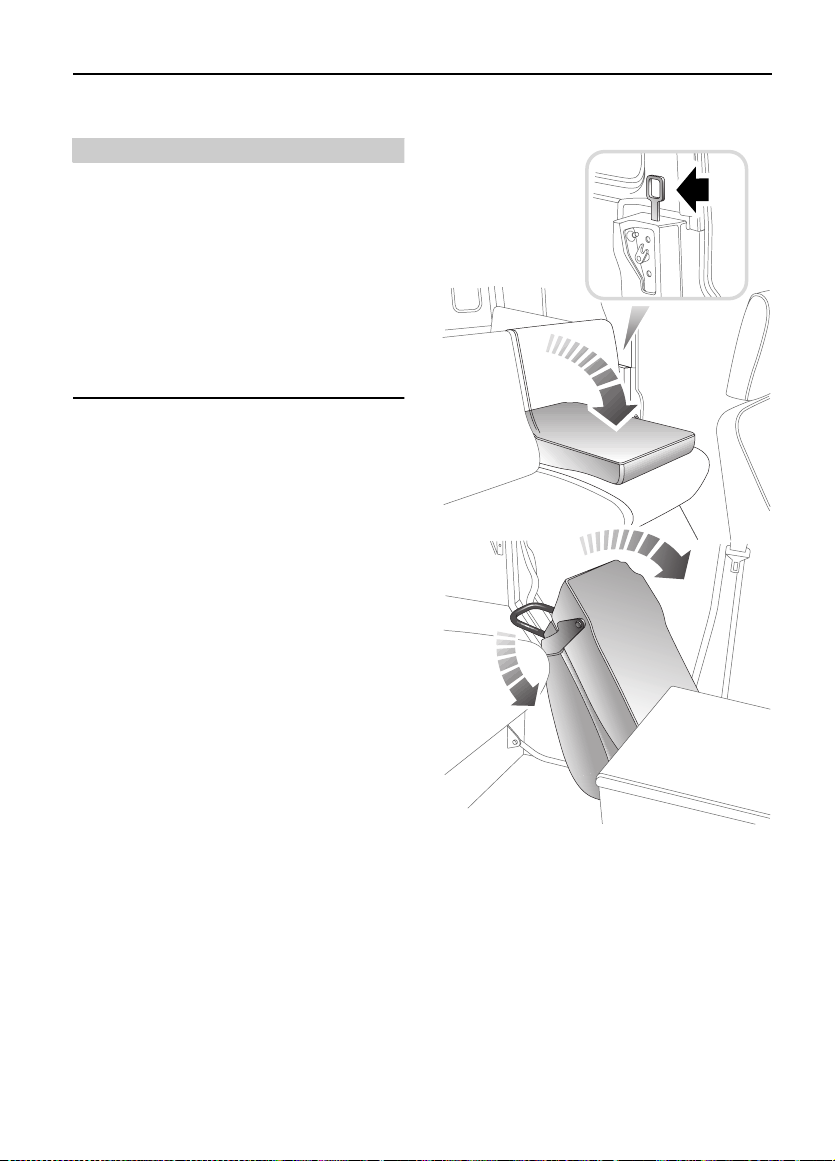
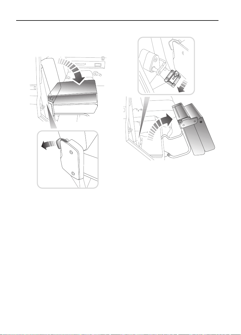
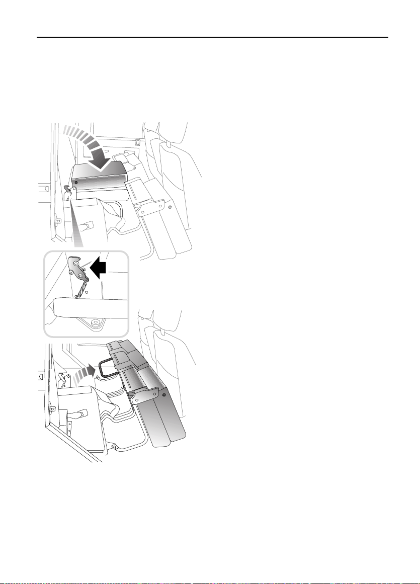
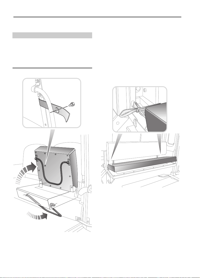
Rear co m p a rtment fold in g se at s
*
WARNING
When the seat is in use, the steel support
must be angled as shown in the illustration
(i.e. pointing away from the front of the seat,
with its foot angled into the floo r where the
floor meets the side of the vehicle).
1. Unclip the re straini ng strap (see inset) and
fold down the seat base.
2. Position the steel seat support as shown
in illustr at io n .
The stee l suppor ts can be folde d fl at aga inst th e
underside of the sea t base when not in use. The
strap (see inset) should be used to secure the
seat base in the folde d posit ion when not in use.
Rear compartm ent bench seats
*
H3714
H3713
These are fix ed seat s and cannot be f olded. The
seat cushions are removable (se e illustration).
26
Page 27

Seat Belts
Seat Belts
SEAT BELT SAFETY
The seat bel ts fit ted to th e front a nd sec ond row
seats are intended for use by adult sized
occupants. Each belt should be used by one
occupant only.
Observe the following precautions:
• DO make sure AL L passen ger s ar e secur el y
strappe d in at all times - even for the
shortes t journeys.
• ALWAYS adj ust seat belt s to eliminat e any
slack in the webbing. DO NOT slacken the
webbing by holding the belt away from the
body - to be fully effective, the se at belt
must remain in fu ll cont ac t wi th the bod y at
all times .
• ALWAYS fi t the lap strap as l ow on the hips
as possible (never across the abdomen),
and ensure that the diagonal belt passes
across the shoulder without slipping off or
pressing on the neck.
• DO NOT wear seat belts over hard, sharp or
fragile items in clot hing, s uch as pens, keys,
spectac les etc.
• Always replac e a seat belt ass embly that has
withstood the strain of a severe ve hicle
impact, or if the webbing shows signs of
fraying.
• Where possi ble use the se at belts t o secu re
large items of luggage that are to be carried
on the seat s - in the event of an accident,
insecure items become flying missiles
capable of causing serious injury.
• DO NOT use a seat be lt that is twist ed or
obstructe d in any wa y th at coul d i mped e its
smooth operation.
• DO NOT allow front seat occ upants to tra vel
with the seat backs reclined steeply
rearwards. Optimum benefit is obtained
from the seat belt with the seat back angle
set to approximately 25 degrees from the
upright (vertical) position.
• DO NOT allow foreign matter (particularly
sugary food an d drink particl es) to en ter the
seat belt locks - such substances can render
the lock s inoperati ve.
• In most countries, all occupants are
required by law to wear a seat belt, unless
they have been issued with a medical
exempti on certificate.
• During pregnancy, women should wear t he
lap belt across t he hips below the baby, wi th
the diagonal belt passing across the
shoulder, between the breasts and to one
side of the baby - if in doubt, consult a
doctor.
WARNING
Ensure that all seat belts are worn correctly an improperly worn seat belt increases the
risk of death or serious in jury in the ev ent of a
collision.
27
Page 28
Seat Belts
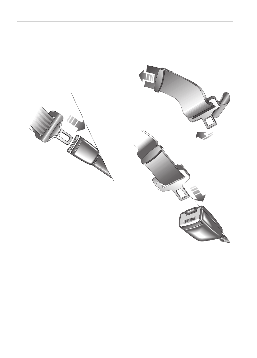
SEAT BELTS
To minimise injury in the event of an accident,
it is important that seat belts are worn correctly.
Read the instructions below and the advice
contained under the heading ‘SEAT BELT
SAFETY’.
Fastening the inertia reel seat belts
H3715
Pull the belt over the shou lder and acros s the
chest and, ensuring that the webbing is not
twisted, insert the metal tongue plate into the
buckl e ne ar est the wea re r - a ‘CLICK’ indicates
that the belt is securely locked.
Releasing the be lt
Press the RED button on the seat belt buckle.
Lap belts
Seat belts are designed to bear upon the bony
structure of the body (pelvis, chest and
shoulder s) and ca n only be worn safe ly with t he
seats in a normal upright position - DO NOT
allow front seat occupants to travel with the
seat stee ply reclined.
NOTE: In so me circumstances, per haps due to
the vehicle being on a slope, the automatic
locking me chanism may engage, p reventi ng the
initial extension of the belt. This is not a fault ease the bel t free and use it.
H3716
To adjust, pu ll t he sli der a lon g the bel t an d f ee d
the webbing th ro ugh t he buckl e until the belt is
comforta bly tight. Then, inser t the metal ton gue
plate into the buckle ne arest the wearer - a
‘CLICK’ indicates that the belt is securely
locked. W hen not in use, the lap be lts shou ld be
fastened.
28
Page 29

Seat Belts
CARING FOR SEAT BELTS
Regularly inspect the belt webbing for signs of
fraying, cuts and wear; also pay particular
attention to the condition of the fixing points
and adjusters.
DO NOT bleach or dye the webbing and avoid
contaminating the webbing with polish, oil or
chemicals (see ‘CLEAN I NG THE INTERIOR’,
page 122).
Testing inertia reel belts
• With the seat belt fastened, give the
webbing near the buckle a quick upward
pull. The buckle must remain securely
locked.
• With the se at belt unfastened, unreel th e
webbing to th e lim it of it s tr avel . Che ck t hat
unreeling is free from snatches and snags
and then allow the belt to FULLY retract.
• Partiall y unreel the webbing, then hold the
tongue plat e and g ive it a quick f orward pull.
The mechanism must lock automatically
and prevent any further unreeling.
If a seat be lt should fail any of these tests,
cont ac t yo u r dealer im m ed i ately.
WARNING
Always repla ce a seat belt tha t shows si gns of
webbing damage or has withstood the strain
of a severe vehicle impact.
29
Page 30

Child Restraints
Child Restraints
CHILD SEATS
The seat bel ts fitted to your vehicle are
designed fo r adults and larger children. It is
very import ant that all infants and young
children ar e r es trai ned in a sui tab le chil d s afety
seat appr opria te to th eir a ge a nd si z e (see ta ble
below). Chi ld safety seats approved for use in
your vehicle are available from Land Rover
dealers.
Only fit a chil d safet y sea t of a t ype a pprove d for
the specific seating positions in your vehicle
(see tabl e) and ensure the manufacturer's
fitting instruct ions are follow ed exactly .
Defender 90 & 110 Station Wagons only
Mass Group
(As displayed on Child Resstraint
packaging)
0 = Up to 10 kg (0-9 months) U X U X
0+ = Up to 13 kg (0-2 years) U X U X
I = 9 to 18 kg (9 mont hs - 4 years) U X U X
II & III =15 to 36 kg (4-12 years) U X U X
U = Suitable for ‘universal’ categ ory rest ra in ts ap pr o ve d for th is ma s s gr o up .
X = Seat pos iti on no t suitable for ch ild r en in th is mas s gr ou p .
Passenger
Accident statistics show that children are
safer when properly rest rained in the rea r
seating positions than in the front. However,
if a forward facing child seat suitable for the
size of the child is available and it is
necessary for the child to travel in the front,
set the seat fully rearwards and use an
approved FORWARD FACING child seat - DO
NOT INSTALL REARWARD FA CING CHILD
SEATS IN ANY FRONT PASSENGER SEAT
POSITION.
Seating Positions
Front
Front
Centre
* = If fitted.
† = Not suitable for the majority of child restraints which require a 3-point seat belt for
attachment, however, a chi ld restrai nt may be used in these posit ions provide d that it is
specifically designed and sold for use with a 2-point seat belt.
*†
WARNING
Rear
Outboard
Rear
Centre
*†
NOTE: The side facing folding or fixed bench
seats fitted in the loa d carrying area of some
vehicle s, are not suitable for fitting child safety
seats.
30
Page 31

Door Mirrors
Door Mirrors
EXTERIOR MIRRORS
NOTE: Objects viewed in exterior mirrors may
appear further away than they actually are.
Manually ad justable mirr ors
H3650
Move the mirror glass to the required position.
Folding the mirror body
Positioning the mirror for towing
H3652
To improve rear visibility when towing, the
mirror s can be folded outwards (see
illustration), so that the mirror stem is at 90º to
the side of the vehicle, increasing the field of
vision.
H3651
The door mi rr ors ar e d esign ed t o f old f or war ds
or rearwards on impact. They can also be folded
back towards the side windows into a ‘park’
position to enable the vehicle to negotiate
narrower openings.
31
Page 32

Instruments
INSTRUMENT PANEL
Instruments
12
39
6
120
km/h
H3724
8
1. Speedometer
Indicates road speed in kilometres per hour.
2. Anti-theft alarm indicator light
Indicat es the status of the alarm system (see
‘Anti-theft alarm indicator ligh t’, page 13).
3. Total distanc e (odometer ) and trip recor der
Indicates the total distance or the individual
journey distance trav elled by the vehicle.
4. Trip reco rder reset button
Briefly press and release the button to change
the di gital display betw e en either the tota l
distanc e travelled , or the individual journey
distance. Pr ess and h ol d t he but t on to re set the
trip re co r de r to ze ro .
5. Fuel gauge
The pointe r indicates the fuel level wh en the
starter sw itch is turned to position ‘II’.
NOTE: When the fuel remaining drops to a
minimum of 9 litres, the low fuel warning light
will illuminate (s ee ‘WARNING LIGHTS’,
page 33).
567
40
ABS
TC
1
100
80
km/h
60
20
0
3
4
2
120
140
160
180
200
6. Temperature gauge
Once the en gine cool ant has rea ched i ts normal
operating temperature, the pointer should
remain bet w een the BLUE and RED segments.
If the point er moves towards the RED seg ment,
this indicates that the engine coolant is
becoming too hot. Should the pointer move
INTO the RED segment, severe engine damage
could occur. In this case, stop the vehicle as
soon as saf ety permits and allow the e ngine to
idle fo r fi ve mi nu te s in ord er to co ol d own - DO
NOT SWITCH OFF. Seek qualified assistance
before continuing.
7. Clock
For furt her informat ion on setting the time on
the clock , see ‘CLOCK’, page 51.
8. Warning lights
For furt her informat ion on the funct ionality of
the warning lights, see ‘WARNING LIGHTS’,
page 33.
32
Page 33

Warning Lights
WARNIN G LIG HT S
120
km/h
H3723
Warning Lights
ABS
TC
The location and specification of the warning
lights may v ary a cco rdi ng to model an d mar ket
requirements.
WARNING
DO NOT drive if a RED warning light remains
on once the eng ine is running or il luminates
whilst d riving .
Check engine - AM BER
The light illu m i na te s as a bulb and
system check when the starter
switch is turned on, and
extingu ishes as soon as t he engine is sta rted.
Illumination at any other time indicates an
engine fault - if the light illuminates while
driving, avoid high speeds and seek qualified
assistance urgently.
Glow plug - AMBER
Illumi nates w hen th e start er swi tch
is turned to position ‘II’. Wait for
the light to extinguish before
starting the engine.
*
Low oi l pr essure - RED
The light il luminates as a bulb
check when the starte r sw itch is
turned to position ‘II’ and
extinguishes when the engine is starte d. If the
light remains on, flashes on and off, or
illum inates wh ilst dri ving, stop the veh icle as
soon as safety permits and SW ITCH OFF
THE ENGINE IMMEDIATELY. Seek qualifi ed
assistance before driving. Always check the oil
level when thi s lig h t illu min a te s .
Direction indicators - GREEN
The left or ri ght warning light
flash es in tim e w ith the
corresponding left or right
direction indicator lights whenever they are
operated. If the warning light fails to flash, or
flashes very rapidly, this may indicate a bulb
failure in one of the direction indi cator lights.
If the ha zard switch is pressed, b oth warning
lights will flash in conjunction with the direction
indicator lig hts.
Battery charging - RED
The light il luminates as a bulb
check when the starte r sw itch
is turned to position ‘II’ and
extinguishes once the engine is running . If it
remains on, or illuminates whilst driving, a fault
is indicated. Seek qualified assistance u rgently.
33
Page 34

Warning Li ght s
Headlight main beam - BLUE
Illuminates when the headlights
are switched to main beam.
Low fuel - AMBER
Illumin at es wh e n th e fu e l
remaining in the tank drops to a
minimum of 9 l itres. If the light
illuminates, refuel at the first op p o rtunity.
Handbrake, brake fluid - RED
The light illumi n ates for about 3
seconds a s a bu lb chec k when the
start er switch is turned on. It also
illuminat es when the handbrake is applied with
the st ar ter switc h in positio n ‘II’. The light
should extinguish when the handbrake is fully
release d or shortly af ter the electrical circuits
are switched on. If the light illuminates whilst
driving, a f ault with the brak ing system is
indicated. Stop the veh icle as soon as sa fety
permits and seek qual i f ied assi st an ce before
continuing.
Anti-lock braking system - AM BER
Illuminates for approximately 1
second as a bulb and system check
when th e sta rter sw itch is t urned to
position ‘II’, and briefly extinguishes before
coming on again. If the light does not
extinguish an d the n c ome on a gain, t hen a f ault
occurred with the ABS system and you should
consult a qu alified dealer at the earliest
opportunity. The warning l ight will remai n o n
until the vehicle is driven above approxim ately
7 km/h.
If the light remains on or subsequently
illuminates while driving, a fault h as been
detecte d by the self monitoring system. This
means that full ABS control may not be
available and y ou shoul d co nsult your dea ler at
the earliest opportunity.
*
Traction Control - AMBER
Illumin ates as a bulb check when
the start er switch is turned to
position ‘II’ and extinguishes after
approxi mately 3 seconds. The l ight illum inates
for a mini mum of 2 second s, whene ver tr action
control is operating.
If the warning light flas hes (for at least 10
seconds) traction control has been operating
for too long and has temporar ily shut down to
allow th e s yst em to co ol - t his wil l on ly o ccu r in
extreme conditions.
If the ligh t illuminat es conti nuousl y, a faul t with
the system is indicated; seek qualified
assistance.
Rear fog guard li ghts - AMBER
Illuminates whenever the rear fog
guard lights are on.
NOTE: In clear co ndi tion s, rear fo g gu ar d lig ht s
can dazzle other road users. Use ONLY when
visibility is severely restricted.
Engine immobilisation - RED
Flashes duri ng a ny attem pt t o s ta rt
the engine wh en the engine is
immobilised.
Heated rear screen - AMBER
Illuminates when the rear scre en
heater is operating.
Differential lock - RED
Illuminates whenever the
differential is locked. If the light
remains on after the differential
lock is dise ngaged, tran smission ‘wind-up’ may
be present. Reversing for a short distance and
then going forward will usually ‘unwind’ the
transmission. If the light remains on, contact
your deal er as soon as possi ble.
*
34
Page 35

Warning Lights
Hazard warni ng light s - RE D
Illuminates in conj unction with the
direction indicator warning lights,
when the hazard war ning l ights are
operated.
Trailer dir ection indicators - GREEN
The light illuminates briefly as a
bulb chec k wh en the st ar ter swi tc h
is turned to position ‘II’. If a trailer
is attached, the light illumi nates in conjunction
with the ve hicle direction indicator lights to
show that all trailer indicator lights are
functioning correctly. In the event of a bulb
failure on the trailer, the warni ng light flashes
once and the n rem ains off.
Sidelights - GREEN
Illumi nates whenever the si delights
are on.
Transmiss ion oil temperature - RED
Illuminates as a bulb che ck w hen
the start er switch is turned to
position ‘II’ and extinguishes after
3 seconds approx. If the light illuminates whi le
driving, the gea rb ox oi l te mper ature is too hi gh
(most l ikel y to occur i n very hot we at her d uri ng
continuous high speed driving, or whilst towing
heavy loa ds on steep inclines or if the
handbrake has been applied while driving).
If the li ght ill uminates , reduce s peed. If the li ght
remains on, stop the vehicle and allow the
gearbox to cool. Do not drive unti l the light has
extinguished. (Depending on the ambient
temperat ure an d the carr ying loads impo sed on
the vehicle, it may take several minutes before
the light extinguishes and it is safe to drive).
*
Fuel filte r - AM B ER
3 seconds approximately. If the ligh t
illuminates while driving, this indicates the
presenc e of excessiv e amounts of wate r in the
fuel. You ma y co ntinu e dr ivin g but sh ould se ek
qualified assistance at the earli est conveni ent
time.
*
Illuminates as a bulb check when
the star ter switch i s turned to
position ‘II’ and extinguishes after
35
Page 36

Lights & Indic ators
Lights & Indicators
DIRECT IO N IN DIC AT OR S
H3629
Move the lever DOWN to indicate a LEFT turn,
and UP to indicate a RIGHT turn (the
appropriate GREEN warning light on the
instrument panel will flash in time with the
direction indicators).
Hold the lever part-way up or down against
spring pressure to indicate a lane chan ge.
LIGHTS
0
1
2
H3632
Side, tail an d instrument panel l ights
Push the light ing switch to posi tion 1.
Headlights
Push the light ing switch to posi tion 2.
Headlight main and dipped beams
3630
With the he adlight s switched on, push t he lev er
away from the steering wheel to change
headlight beams (BLUE warning light glows
when the headlights are on main beam).
To flash the headlights, pull the lever part way
towards the steering wh eel and rele ase.
36
Page 37

Lights & Indicators
Headli ght levelling*
H3669
The angle of the headlight beams is affected by
the distri bution of weigh t inside the veh icle. The
headlights should be adjust ed so that the point
at which the beams meet the road surface
ahead of the vehicle provides adequate
illumination without dazzling other road users.
The four-position switch should be used to
adjust t he headlight beams in relation to the
vehicle loadings identified opposi te.
Position Loading Condition
0 Driver, or driver and front
passenge r only
(loadspace empty).
1 All seats occupied
(loadspace empty)
2 All seats occupied with
loadspace loaded to max.
permissi ble rear axle weight.
3 Driver only with loadspace
loaded to max. permissible
rear axle weig h t.
Vehicles fitted with front seats only
Positions ‘1’ and ‘2’ should only be used when
required, according to the distribution and
weight of the load being carried.
37
Page 38

Lights & Indic ators
FOG LIGHT S
H3692
Rear fog guard lights
Press to operate, press a second
time to switch off (the indicator
light in the switch illuminates when
the fog guard lights are switched on). The rear
fog gu a r d lights illumin ate ONLY wh en the
headligh ts a re al so sw it che d o n, an d t he st art er
switch is turned to position ‘II’. Switching off
the headli ghts, or turning the starter switch to
position ‘0’, will au tomati ca lly exti ng u is h th e
rear fog guard lights too (the fog guard lig hts
will not illuminate ag ain unless selected
manually).
HAZARD WARNING LIGHTS
H3693
Press to ope rate; all the direction
indicator lights (including those
fitted to a trailer) will flash
togethe r. Use ONLY in an emergency to warn
other road users when your stationary vehicle
is causing an obstruction, or is in a hazar dous
situation. Remember to switch off before
moving away.
ALWAYS remember to switch the fog guard
lights off as soon as visibility permits ; in clear
conditions fog guard lights can dazzle other
road users!
38
Page 39

Wipers & Washers
Wipers & Washers
OPERATING
The wipers and washer s will only ope ra te whe n
the star ter switch is turned to position ‘I’ or ‘II’.
IMPORTANT INFORMATION
• DO NOT operate the wipers on a dry
screen.
• In freezing or very hot conditions,
ensure t hat the bl ades are not froze n or
stuck to the glass.
• In winter, remove any snow or ice from
around the arms and blades, including
the wiped area of the win d screen and
the heate r air intakes.
NOTE: If the wiper blades have stuck to the
glass, a thermal cut-out may temporarily
prevent the wiper mot or from oper ating. If t his
is the case, switch the wipers off, free them
from the obstruction and then switch on again .
WINDSCREEN WIPERS
H3627
Intermittent wipe
Pull lever down.
Normal speed wipe
Push leve r up to first position.
Fast speed wipe
Push leve r up to second posi tion.
Single wipe
H3626
Push the lever up against spring press u re and
release immediatel y.
NOTE: With the lever held up, the wipers will
continue operating at slow speed until it is
released.
39
Page 40

Wipers & Washers
WINDSCREEN WASHER
H3628
Press to operate. The windscr een wipers will
operate in conjunction w ith the washers for as
long as the lever pressed, t he wipers conti nuing
for a further 4 sec on d s af ter the leve r is
released.
REAR WINDOW WIPER AND WASHER
H3672
Rear window wiper
Press to operate: the wiper
operates continuously until the
switch is p ressed again .
Rear window washer
Press and hold switch for the
required duration of windo w
washing. Washing stops as soon
as the swit ch is release d.
40
Page 41

Horn
HORN
H3631
Press the end of the lever to operate the horn.
Horn
41
Page 42

Manual Windows
Manual Windows
FRONT AND R EA R WI ND OW S
Raise or lower the window by rotat ing the
handle mount ed on the door trim pad.
SLIDING REAR WIN DOWS*
H3609
To open, press the catch tongues together,
slide the window to the desire d position and
relea s e th e ca tch, ens uring tha t it l o ca te s
securel y in the sockets, locking the window in
position.
42
Page 43

Electric Windows
Electric Windows
ELECTRIC WINDOWS
H3671
Operating th e windows
The elect ric windows c an be o per ated whe n t he
starte r sw itch is at position ‘II’ by pressing the
switche s on the centre console as follows:
Press and HOLD the bottom of a switch t o lower
and the t op of a s witch to ra ise. Th e windo w will
stop moving as soon as the switch is released.
WARNING
Acciden tal cl osing of an ele ctri call y ope ra ted
window on fingers, hands or any vulnerable
part of the body, can resul t in serious injury.
Always observe the following precautions:
ENSURE childr en are kep t clear whi lst rais ing
or lowering windows.
ENSURE that all adult passenger s are familiar
with the cont ro ls and t he po tenti al dan ger s of
electrically operated windows.
43
Page 44

Sunroof
Sunroof
SUNROOF*
N
E
P
O
O
P
E
N
H3613
The sunroof can be opened to varying degrees
or, if required, can be removed completely.
• To OPEN the roof: Turn the hand wheel
anti-clockwise to give the desired o pening.
• To CLOSE the roof: Turn the hand whee l
clockwis e until resistance is felt.
WARNING
ENSURE the sunroof is not obstructed when
opening or closing.
To remove the su nroof
H3612
Open the sunr oof fully and push the catch
rearwards (as arrow ed in illustration) to
disengage the handwheel mec hanism.
DO NOT allow passengers to extend any part
of their bodies through the sunroof aperture
while the vehicle is moving - inj ury from
flying debris, branches of trees or other
obstructions could occur.
ALWAYS close the roof when the vehicle is
unattended.
H3600
Remove the sun roof by tilting upwards and
lifting rearwards to disengage the two locating
lugs.
WARNING
DO NOT stor e t he sunr oof loos e in t he ve hicle .
DO NOT remove the sun roof whilst t he vehi cle
is moving.
Refit th e sunroof by fol lowing the sam e
procedure in reverse.
44
Page 45

Heating & Ventilation
mph
VENTILATION
Heating & Ventilation
12
39
6
L
A
N
-
R
O
70
50
100
80
km/h
120
60
30
90
140
40
160
20
180
110
10
0
0
D
-
mph
V
E
R
H3759
The ventil ation sy stem pr ovides f resh or heated
air to the interior of the vehicle.
NOTE: Always keep th e ext erior a ir i ntake g rilles
clear of o bstructio ns such as leaves, snow or
ice.
The temperature of the air supplied to the
windscreen a nd foot level ve nts is cont rolle d by
the heater, while the fresh air vents in the upper
fascia prov id e fresh a ir o nly. T he loca ti on of t he
vents is shown in the illustration above.
Information conce rning the oper ation of the
heating and ventilation syst em, appears on the
foll o w ing pages.
Fresh air vents
H3719
To open the vents in the upper fascia, pull one
of both knob s out and push the l evers
downwards . To close the vents, pull the knobs
out and raise the levers.
These vents provide unhe ated fresh air only.
45
Page 46

HEATER CONTROLS
Heating & Ventilation
2
1
H3680
NOTE: For vehicles fitted with an air
conditioning system, the controls and air
conditioni ng vents are des cribed on a l ater page
(see ‘AIR COND ITI ONING CONTROLS*’,
page 48).
1. Temperature control
Move the leve r downwards (towards the RED
arrow) to i ncrea se ai r tem pera tur e, or up war ds
(towards the BLUE arrow) to reduce air
temperature.
2. Air distribution control
• Lever fully up - windscreen vents only.
• Lever midway - foot level and windscreen
vents.
• Lever fully down - foot level vents (also
provides so m e air to the windscreen).
3
3. Air bl o w er control
• Lever at position ‘0’ - no air will enter the
vehicle through the windscreen and foot
level vents.
• Lever between positions ‘0’ and ‘1’ -
progress ively mo re ai r will enter the v ehicle,
depending solely on the ram effect of the
vehicle m oving through the air.
• Lever betw een pos it ions ‘1’ and ‘2’ - the fan
will operate and progressively increase in
speed.
46
Page 47

Heating & Ventilation
USING YOUR HEATER
The follow ing exa mples o f basi c heater settin gs
are inte nded as a general guide; the ai r
distribution, temperature and blower controls
can then be further adjusted to suit your
comfort requirements.
Always remember that full heating is not
available until the engine has reached its
normal operating temperature.
Maximum heating
H3681
• Temperature control - fully down.
• Distribution control - midway.
• Air blower control - fully down .
• Fresh air vents - fully closed.
Demisting and defrosting
H3682
• Temperature control - fully down.
• Distribution control - fully up.
• Air blower control - fully down.
• Fresh air vents - full y open for demisting
(fully cl osed for defrosting).
• Opening a window may improve demi sting.
Maximum ventilation
H3683
• Temperature control - fully up.
• Distribution control - fully down.
• Air blower control - fully down.
• Fresh air vents - full y open.
47
Page 48

Air Conditioning
Air Conditioning
AIR CONDITIONING CONTROLS*
1
H3685
2
1. On/off blower control
Rotate clockwise to the first position to turn on
the air conditi oning. Rot ate furt her (posit ions II
and III) to in crease the flow of conditioned air
from the four vents in the lower fascia.
NOTE: The air conditioning will only operate
with the engine running.
2. Temperature control
Rotate clockwise (positions I to III) to obtain
progressively cooler air.
Air conditioning vents
H3756
The four air conditioning vents located in the
lower fascia can be adjus ted to suit your
requirem ents. T he ad juster in t he ce ntre of each
vent can be use d to adju st volu me an d direct ion
of air. To cut off the supply of air from any
particular vent, slide the adjuster fully to the
left.
General ope rating notes
• For opt imum ope rati ng effi cien cy, ensu re al l
the air co nditionin g vents are open.
• In very humid conditions, sl ight screen
mist in g m a y be experi enced wh e n th e air
conditioning system is turned on. This is a
natural occurrence on most automo tive air
conditioning systems. It is not a fault and
misting wi ll clear after a few seconds once
the air conditioning system is opera ting.
• If the temperature inside th e vehicle is
higher than that outside when you start the
engine , it w ill tak e time fo r th e ai r
conditioning to become fully effective. It is
best to ventilate the vehicle by opening the
windows and sett ing the controls to
‘Maximum cooling’. When th e vehicle has
been ventilated, close the windows and set
the blower controls for per sonal comfort.
• Operating the air conditioning takes power
from the engi ne and conseq uently incr eases
fuel consumption.
48
Page 49

Air Condition ing
• All air conditioning sy stems need to be
operate d fo r a sh ort wh il e eve ry week (even
in winter) to maintain them in peak
condition.
• Surplus water produced by the
dehumidifying process is expelled from the
system via drain tubes beneath th e vehicle.
This ma y result in a small pool of water
forming on the road when the vehicle is
stationary and is not a cause for concern.
USING THE AIR CON DI T IO NI NG
Air conditioning provides addition al cooling to
the vehic le interior and also reduces the
moisture content of the air.
It is important to keep windows, s unroof
fresh air vents closed during operation.
Air conditioning settings
* and
Normal cooling
H3689
Temperature control - set to positions I or II.
Blower control - set to desired speed.
Maximum cooling
H3691
Temperature control - set to position III.
Blower control - set to posi tion III.
H3686
When air condi tioning is t o be u sed, ens ure t hat
the fresh air vents are closed, and the heater
unit co n tr ols are set as shown , i. e.
Air blower control - position ‘0’.
Temperature control - fully up.
Distribution control - fully up.
The following examples of air condition ing
settings are includ ed for your guidance.
49
Page 50

Heated Screens
Heated Screens
HEATED FRONT SCREEN AND REAR
WINDOW
H3742
Heated front screen*
Press to operate (t he indicato r light
in the switch illuminates); press a
second time to switch off (the
indicator light extinguishes). After 8 minutes
continuous operation, the heater switc hes off
automati cally. Note that the hea ted front scree n
operates only with the engine running.
WARNING
DO NOT stick labels over the heating
elements, a nd DO NOT scrap e or use abras ive
materials to clean the insid e of the window.
Heated rear window
Press to operate; press a second
time to switch off. The ind icator
light in the switch illuminates while
the heating elements are switched on and
extinguishes when they are turned off.
*
50
Page 51

Interior Equipment
INTERIOR LIGHTS
Interior Equipment
CLOCK
F
F
O
12
N
O
H2592
Switch positions:
• ‘OFF’ - Light permanently off.
• ‘ON’ - Light illuminates continuously.
With the switch in the centre position, the
interior light illuminates automatically
whenever a door is op ened or the al arm sys tem
is disarmed. The light remains illuminated for
15 seconds after the doors are closed , or until
the star ter switch is turned on.
NOTE: Any su bseque nt ope ning and sh utting o f
doors pri or to the start er switch bei ng turned
on again, wi ll caus e the 1 5 secon d delay f eatur e
to operate.
On Station W ago n mo de ls , ill uminatio n of the
interior lights is also activated by opening and
closing the tail door.
After driving, the interior lights will fade and
then exti nguish as soo n as the vehi cle is loc ked
or when the last door is closed.
9
3
6
H3625
To adjust the time, use a ballpoint pen or similar
probe to advance or put back the time, by
pressing in the left or right hand buttons at the
bottom of the clock bezel.
NOTE: The clock w ill need to be reset if the
battery is disconne cted.
NOTE: When the lig ht is swi tched fo r autom atic
operation (switch in centre position), a
‘time-out’ funct i on exti ngu ishes the lig hts after
8 minutes approx. if a door is left open, to
prevent the battery from discharging.
51
Page 52

H3668
Interior Equipment
CIGAR LIGH T E R*
With the starter switch turned on, press the
lighter in to heat up. When it has reached the
correct tem perature it will partial ly eject and
can then be withdrawn for use.
• ONLY hold the cigar lighter by t he handle.
• DO NOT plug acces sories into the cigar
lighter socket unless they are approved by
Land Rover.
ASHTRAY
WARNING
DO NOT use the asht ray for disp osing of waste
paper or other combustible items.
Lift the li d of the ashtray to open. To remove,
carefull y prise t he body of the as htray out of t he
fascia panel.
52
Page 53

Interior Equipment
3
CUBBY BOX
762
Lift up th e catch (see inset) to release the lid.
INTERIOR REAR-VIEW MIRROR
H3649
The manual rear view mirror can be dipped to
reduce gl are from the headlights of following
vehicles . At nigh t, move the l ever a t t he b ase of
the mirror forward to ‘dip’ the mirror. Normal
visibility is rest ored by pulling the lever back
again.
WARNING
In some ci rcumst ances the vi ew reflec ted in a
‘dipped’ manua l mir ror can c onfus e the dri ver
as to the precise location of following
vehicles. Remember to take additional care!
53
Page 54

Side & Rear Step
STEPS
H3653
Side & Rear Step
Rear step
H3660
Side steps
The side and tail door steps are hinged to
enable them to be folded down when in use, or
up when not required.
54
Page 55

In-Car Telephones
In-Car Telephones
IN-CAR TELEPHONES
WARNING
Refrain fr om opera ting a tel ephone fi tted wit h
its own aerial inside the vehicle (see main
text).
Your vehicle utilises a number of electronic
systems. These system s may b e affect ed by the
use of mobile com municatio n equipment insi de
the vehic le. However, the use of an external
aerial wil l greatly reduce the likel ihood of this
occurrence.
For your safety, always note the fol lowing
precautions before fitting or using an in-car
telephone, or any mobile com m unication
equipment.
• Only use an insta l la tion ki t incorp ora tin g an
aerial external to the vehicle.
• Ensure tha t the in st alla ti on is carri e d out by
a competent installer.
• Refrain fr om operating a mobile pho ne fitted
with its ow n aerial in si de the vehicle - th e
electrom agnetic field radiated by the phone
may interfere with the vehicle's electrical
systems.
For your safety
WARNING
Using any hand-held appliance while driving
can be danger ous. Always stop the vehicle
before making a call and ensure the
telephone is switched off whi le you are
driving.
55
Page 56

In-Car Entertainment
In-Car Entertainm ent
RADIO A E RIAL
H3673
Set into th e front wing , the te lesco pic aeri al can
be raised or lowered manually.
IN-CAR ENTERTAINMENT
Radio cassette player
Full operating instructions for any audio
equipment fit ted as standard to your vehicle,
are conta ined in the ‘In-Car En tertai nment’ book
in the vehicle literature pack.
56
Page 57

Driving & Operating
Starting & Driving
STEERING COLUMN LOCK . . . . . . . . . . . . . . . . . 59
STARTER SWITCH. . . . . . . . . . . . . . . . . . . . . . . . 59
STARTING - Diesel engines . . . . . . . . . . . . . . . . . 60
DRIVING . . . . . . . . . . . . . . . . . . . . . . . . . . . . . . . 61
FUEL ECONOMY . . . . . . . . . . . . . . . . . . . . . . . . . 62
AUXILIARY EQUIPMENT . . . . . . . . . . . . . . . . . . . 63
EMISSION CONTROL SYSTEM . . . . . . . . . . . . . . 63
Catalytic Conv e rter
CATALYTIC CONVERTER. . . . . . . . . . . . . . . . . . . 64
Fuel Filling
SAFETY ON THE FORECOURT . . . . . . . . . . . . . . . 65
FUEL FILLER . . . . . . . . . . . . . . . . . . . . . . . . . . . . 65
TYPE OF FUEL . . . . . . . . . . . . . . . . . . . . . . . . . . . 66
FUEL FILLING . . . . . . . . . . . . . . . . . . . . . . . . . . . 67
EMPTY FUEL TANK . . . . . . . . . . . . . . . . . . . . . . . 67
FUEL CUT-OFF SWITCH (Td5 models). . . . . . . . . 68
Manual Gearbox
GEAR LEVER . . . . . . . . . . . . . . . . . . . . . . . . . . . . 69
Transfer Gearbox
TRANSFER GEARBOX . . . . . . . . . . . . . . . . . . . . . 70
USING THE TRANSFER GEARBOX. . . . . . . . . . . . 70
THE DIFFERENTIAL LOCK . . . . . . . . . . . . . . . . . . 71
Page 58

Brakes
FOOT BRAKE. . . . . . . . . . . . . . . . . . . . . . . . . . . . 73
HANDBRAKE. . . . . . . . . . . . . . . . . . . . . . . . . . . . 74
ANTI-LOCK BRAKES. . . . . . . . . . . . . . . . . . . . . . 74
Traction Control
ELECT RON IC TR AC TI ON CONTROL . . . . . . . . . . 76
Towing
TOWING . . . . . . . . . . . . . . . . . . . . . . . . . . . . . . . 77
Load Carrying
LUGGAGE SPACE . . . . . . . . . . . . . . . . . . . . . . . . 79
ROOF RACKS . . . . . . . . . . . . . . . . . . . . . . . . . . . 79
Ancillary Equipment
WINCHES . . . . . . . . . . . . . . . . . . . . . . . . . . . . . . 80
POWER TAKE-OFF DRIVES. . . . . . . . . . . . . . . . . 81
HAND THROTTLE . . . . . . . . . . . . . . . . . . . . . . . . 82
58
Page 59

Starting & Driving
Driving& Operating
Starting & Driving
STEERING COLUMN LOCK
H3584
To unlock the steering column
Insert the k ey FULL Y and turn the s tart er swi tch
to posi tion ‘I’. A small movement of the steering
wheel may be necessary to disengage the
steering lock while t u rning the switch.
To lock the steering column
Turn the key to position ‘0’ and withdraw it
from the s tarter switc h. Turn th e stee ring wheel
slightl y until the lock en ga g es.
WARNING
Once the steering lock is engaged, it is
imposs ible to stee r the vehicle. DO NOT
remove the key or turn the starter switch to
position ‘0’ while the vehicle is in motion.
STARTER SWITCH
The star ter switch is located to the left of the
steering column, and us es the following
sequenc e of key positions to operate the
steer in g lo ck, electrical circ u its and sta rter
motor:
Position ‘0’
• Steering locked (if key is removed) .
• Most ligh ting circuit s are operational,
including: sidelights, headlights, hazard
warning and rear fog guard lights.
Position ‘I’
• Steering unlocked.
• Radio/cassette player can be opera ted.
Position ‘II’
• All instruments, warning lights and
electr ical cir cu its are operati on a l.
Position ‘III’
• Starter motor operates.
Release the key immediately the engine
start s (the key will automatically return to
position ‘II’). Note t ha t ope ra ti on of p osi tio n
‘I’ electrical functions will be i nterrupted
during engine cranking.
59
Page 60

Starting & Driving
STARTING - Diesel engines
WARNING
Never start or leave the engine r unning in an
unventilated building - exhaust gases are
poisonous and contain carbo n mo noxide,
which can cause unconsciousn ess and may
even be fatal.
1. Check th at the handbrake is applied and
that the ge ar lever is in n eutral.
2. Switch off all unnecessary electrical
equipment.
3. Inser t the starte r key and turn the switch
to position ‘II’. Wait until the glow plug
warning light extinguis hes.
NOTE: The waiting time will vary
accordin g to the engine co olant
temperature (when the engine is hot, the
glow plug warnin g li ght will extinguish
almost immediately).
4. Turn th e key t o p osi tion ‘III’ to ope ra te the
starter motor. DO NOT press the
accelerat or pedal while star ting . RELEASE
THE KEY as soon as the e ngi ne is run ning.
If the engine stalls or fails to start, you MUST
return the starter switch to posi tion ‘I’ before
attempti ng to rest art; the engine wil l not sta rt by
turning the starter swit ch from position ‘II’.
In cold weather, or when the batt ery is i n a low
state of charge, depress the clutch pedal while
starting and hold it down until the engine is
running. This will reduc e the load on the
battery.
Precautions
• The diesel engine must not be run above
idle speed until the oil pressure warning
light exti nguishes. This will ensure that
the engine and turbo- charger bearin gs are
properly lubricated before being run at
speed.
• Similarly, ALW AYS allow the engine to
idle for 10 seconds before switching off.
Cold climates
In very col d climates the oil pressure warning
light may take several seconds to extinguish.
Similarly, engine cranking times will also
increase; at -30°C the starter motor may need
to be operated continuou sly for as long as 30
seconds before the eng ine will sta rt. For this
reason, ensure that al l non-essent ial electrical
equipment is switched off.
In temperate climates DO NOT op erate the
starter f or lon ger th an 10 se conds. I f the engine
fails to start, switch off and wait 10 seconds
before re-using the starter.
NOTE: Continued use of the star ter will not only
discharg e the batter y, but may cau se damage to
the st ar ter moto r.
NOTE: In temperate climates, the battery
charging and oi l pressure war ning lights should
extinguish as soon as the en gine is running.
60
Page 61

Starting & Driving
DRIVING
IMPORTANT INFORMATION
Vehicle stability
You r v ehicl e has a hi gh er ground cl ea rance
and, hence , a higher centre of gravity than
ordinary passenger cars to enable the
vehicle to perform in a wide variety of
different off-road applications. An
advantage of the higher ground clearance
is a better view of the road, allowing the
driver to more easily anticipate problems.
Inexperienced drivers should take
additional care, rem em b ering that the
vehicle is not designed for cornering at the
same speeds as conventional passenger
cars, any more than a low slung sports car
is desig ned to perform satisfactorily in
off-road conditions. As with other vehicles
of this type, failure to operate t he vehicle
correct ly may result in loss of control or
even rollover.
Vehicle height
The overall height of your vehicle exceeds
that of ordinary passenger cars . Always be
aware of the height of your vehicle and
check the available headroom before
driving through low entrances. This is
particularly important if the vehicle is fitted
with a roof rac k or if a sunroof is open.
Warming-up
DO NOT warm-up the engine by allowing it to
idle at a slo w speed.
In the interests of fuel econom y, it is advisable
to drive the ve hicle s traight away, rememb ering
that harsh acceleration and labouring the
engine before the normal operating
tempera ture has b een reached can dama ge the
engine.
Running-in
Proper running-in will have a direct bearing on
the reliability and smooth running of your
vehicle throughout its life.
In particular, the engine, gearbox, brakes and
tyres need time to ‘bed-in’ and adjust to the
demands of everyda y motor ing. Dur ing t he firs t
800 km, it is essential to drive with
consideration for the running-in process and
heed the following advice:
• LIMIT maximum road speed to 80 km/h.
Initially , dr iv e th e ve h ic le on a light th ro tt le
and only increase engine speeds gradually
once the r unning-in distance has been
completed.
• DO NOT operat e at full throttle or allow the
engine to labour in any gear.
• AVOID fast acceleration and heavy braking
except in emergencies.
Instrume nts and warning lights
Before driving it is important to fully
understand t he fun ctio n o f the i ns trum ents an d
warning lights (see ‘INSTRUMENT PANEL’,
page 32).
NOTE: Red wa rning lights are of particular
importan ce, illumination indicat ing that a fault
exists. If a red light illuminates, always stop the
vehicle and seek qualified assistance before
continuing.
61
Page 62

Starting & Driving
Power assisted steering
Power assistance is progressively applied the
more the st eeri ng whee l is tur ned. For ex ample;
where manual steeri ng effort wou ld normall y be
greatest (at slow speeds on maximum lo ck),
power assistance is greatest. Similarly, where
only minimal steer i ng effor t would normall y be
required (a t hi gh speed wi th the whe els str aight
ahead), th en powe r assi st ance is als o mini mal,
thus enabling the driver to benefit from
apparently consistent steering effort at all
times.
WARNING
Under no circ um stances must th e steering
wheel be held on ful l loc k for more tha n th irty
seconds in one minute, otherwise the
steering assembly may be damaged.
NOTE: Power assistance is dependent on the
engine running. If the engine is not running,
greater effort will be required to steer the
vehicle.
FUEL ECONOMY
Fuel consumption is influenced by two major
factors:
• How your vehicle is maintained.
• How you drive yo u r ve hicle.
To obtain opti mum fuel economy, it is esse ntial
that your vehicle is maintained in accordance
with the manufacture r's servic e schedule.
Item s su c h as the condi t io n of the air cl ea ne r
element, tyr e p re ssures an d wh eel alig nment
will have a si gnificant effect on fuel
consumption. But, above all, the way in which
you drive is most important . The followi ng hints
may help you t o obtain better value from your
motoring:
• Avoid unnec essary, short, start-stop
journeys.
• Avoid fast starts by acc elerating gently and
smoothly from rest.
• Do not drive in the lower gears for longer
than necessary.
• Decelerate gently and avoid sudden and
heavy braking.
• Anticipate obstructions and adjust your
speed accordingly well in advance.
• When stationary in traffic, select neutral to
improve fu el economy and ai r conditioning
performance.
62
Page 63

Starting & Driving
AUXILIARY EQUIPMENT
WARNING
DO NOT use auxiliary equipment, such as
roller generators, that are driven by one
wheel of the vehicle, as they could cause
failure of the gearbox diff erential. If the
different ial lock is engaged in an attempt to
avoid damage, the vehicle wi ll drive itself
forward.
EMISSION CONTROL SYSTEM
WARNING
Exhaust fumes con ta in p oisono us s ubstan ces
which can cause unconsciousness and may
even be fatal.
•
DO NOT inhale exhaust gases.
•
DO NOT start or leave the engine running
in an enclosed unv ent ilat ed area, or dr ive
with the tai ldoor open.
•
DO NOT modify the exhaust system from
the original design.
•
ALWAYS repair exhaust system leaks
immediately.
• If you thi nk exh aust fumes are en tering t he
vehicle have the cause determined and
corrected immediately.
Land Ro ve r vehicl e s ar e fi t te d w ith emiss i o n
and evapor ative contro l equipment necessary
to meet a number of territorial requi rements.
In many countries it is against the law for
vehicle owners to modify or tamper with
emission con tr ol equi pme nt, or to san ctio n the
unauthorised replacement or modification of
this equip ment. In suc h cases the vehi cle owner
and the re pairer may both be liable for legal
penalties.
It is important to remember that all Land Rover
dealers are properly equipped to perform
repairs and to maintain the emission control
system on your vehicle.
63
Page 64

Catalytic Converter
Catalytic Converter
CATALYTIC CONVERTER*
The exhaust system on some vehicles
incorporates a catal ytic converter, which
converts poisonous exhaust emissions from
the en g in e in to enviro nmenta lly less har m fu l
gases.
WARNING
Catalytic converters can be easily damage d
through impr oper use, part icularly if the
wrong fuel is used, or if an engine misfire
occurs. For thi s reason it is VERY IMPORTANT
that you heed the precautions which follow.
Fuel
ONLY use fuel recommended for your vehicle
(see ‘TYPE OF FUEL’, page66).
Starting the engine
• DO NOT continue to operate the starter after
a few fail ed attempts (unburnt fuel m ay be
drawn into t he exhaust syst em, thereby
poisoning the catalyst), and do not attempt
to clear a misf ire by pressing the accelerat or
pedal - seek qualified assistance.
• When star ting a COLD en gine, D O NOT dr ive
if a misfire is suspected and do not attempt
to clear a misf ire by pressing the accelerat or
- seek qualified assistance.
• Do not attempt to push or tow-start the
vehicle.
Driving
• If a misfi re is sus pecte d, or th e vehicl e lack s
power while driving, provided the engine
has reached its normal operating
temperature, it may be driven SLOWLY (at
risk of catalyst damage) to a Land Rover
dealer fo r assistanc e.
• NEVER allow the vehicle to run ou t of fuel
(the resultant misfire could damage the
catalyst).
• Consult your dealer if your vehicle is
burning excessive oil (blue sm oke from the
exhaust) , as this wil l progressively reduce
catalyst efficiency.
• On rough ter rain d o no t a llow t he unde rs ide
of the vehicle to be subjected to heavy
impacts which could dama ge the cataly tic
converter.
• DO NOT overload or excessive ly ‘rev’ the
engine.
• DO NOT switch off the engine when the
vehicle is in motion with a drive gear
selected.
WARNING
Exhaust system temperatures can be
extremely high - DO NOT park on ground
where combustible materials such as dry
grass or leaves could come into contact with
the exhaust system - in dry weather a fire
could result.
Vehicle maintenance
Any engine misf ire, los s of engine per forma nce
or engine run-on, could seriously damage the
cataly tic converter. For this reason, it is vital
that unqual ified pe rsons do not tamper with the
engine, and that regular systematic
maintena nce is carried out by a Land Rover
dealer.
64
Page 65

Fuel Filling
Fuel Filling
SAFETY ON THE FORECOURT
WARNING
Petroleum gases are hi ghly i nflamma ble a nd,
in confined spaces, are also extremely
explosive.
Always take sensible precautions when
refuelling:
• Switch off the engine.
• Do not smoke o r us e a na ked fl ame or l ight ,
or operate a m obile phone.
• Take care not to spill fuel.
• Do not overfi ll the tank.
FUEL FILLER
WARNING
DO NOT fully remove the filler cap until any
captive t ank p ressure has b een rel eased (wait
until the hissing stops).
H3637
The fuel filler is located in the rear right-hand
body side . To unlock the f uel cap:
1. Insert t he smaller metal key and turn it 90
degrees clockwise.
2. Turn the key 90 de grees anti-clockwise
and then remove.
The cap should then be unscrewed gradually,
as it is designed to allow the fu el tank to vent
during the first half turn. Carefully loosen the
cap one half tur n until resist an c e is felt, and
allow fuel tank pressure to be released. Once
the pressure is released (hissing has stopped),
it is safe to fully remove the filler cap.
65
Page 66

Fuel Filling
H3638
When replac ing, ens ure th at the key is re move d
from the lock, then tighten the cap clockwise
until you hear the fuel cap ratchet click at least
thre e times. Thi s loc k s the cap (th e ke y i s no t
needed). Finally, reposition the ke y cover over
the lo ck .
TYPE OF FUEL
Use di es e l or au t om o t i ve ga s o i l (A G O ) to
EN 590.
The quality of diesel fuel (Derv) can vary in
differen t co untri es and onl y c lean, goo d qu alit y
fuel should be used. It is important that the
sulphur content of diesel fuel does not exceed
0.3%; in Europe all supplies should be within
this limit, but in other parts of the world, you
should check with your suppli er.
Ensure the fuel filter el ement is ch anged and the
fuel se d im enter drained, at the reco m m e nded
service intervals.
If good quali ty dies el fuel i s unava ilable and i t is
necessar y to use poor quality fuel, it may be
necessary to have the fuel filter/sedimenter
drained regularly.
NOTE: The use of paraffin (k erosene) as a diesel
fuel ad d iti ve is illeg a l in th e U K.
WARNING
If the fuel tank is accidentally filled with
petrol it is ESSENTIAL that you contact your
dealer BEFOR E attempti ng to start t he engine!
66
Page 67

Fuel Filling
FUEL FILLING
WARNING
DO NOT atte mpt to fi ll the tan k to its maximum
capacity. If the vehicle is to be parked on a
slope, in d irect sunlight, or high ambient
temperature, expansio n of the fuel could
cause spillage.
Filling station pumps are equipped wi th
automatic c ut-of f sensin g to avoid f uel spil lage.
Fill the ta nk SLOWLY until the filler nozzle
automatically cuts-off the supply. DO NOT
attempt to fill t h e tank beyond this point or
spillage could result due to expansion of the
fuel.
The diesel pumps on garage forecourts fill at a
maximum of 45 litres per minute. Use of
commercia l vehi cl e dies el pumps with a hi ghe r
fill rate, may result in premature pump cut-off
and fuel spillage.
EMPTY FUEL TANK
Td5 diesel engine vehicles
After running the fuel tank dry, refue l the tank
with at l east 4.5 lit res of diesel fuel, then carry
out the foll owing procedure:
1. Turn off the starter swit ch and wait for 15
seconds.
2. Turn the star ter key to position ‘II’ and wait
for 30 seconds.
3. Repeat steps 1 and 2 six times.
4. After the final 30 second period, fully
depress the accelerator pedal.
5. Keeping the pedal depressed, start
cranking the engine.
6. Continue cra nking the en gine a nd a s soon
as the engine is firing smoothly, ease th e
accelerator pedal back to approximately
halfwa y throug h it s tra vel , and re le ase the
starter key. The engine sh ould now be
running.
7. If the engine fails to start, repeat the
process.
During the abov e pr ocedur e, the f uel pump will
be heard t o operate (pri m ing the engine ). This
noise is not cause for concern.
IMPORTANT INFORMATION
The engine must NOT be cranked for more
than 20 sec onds in any one peri od.
If the above procedure is carried out on a
vehicle that has NOT run out of fuel, it will
result in the engine flooding with fuel
and faili ng to start.
Tdi diesel engine vehicles
If the vehicle runs out of fuel, then qu alified
assistance may be required to prime the fuel
system before the eng ine can be restarted.
67
*
Page 68

Fuel Filling
FUEL CUT-OFF SWITCH (Td5 models)
H3582
The fuel cut-o ff swit ch i s a sa fe ty de vice w hic h,
in the event of a collision or sudden impact,
automatically cuts off the fuel supply to the
engine.
The switch is located on the engine
compartment bulkhead. Af ter an impact, the
switch mus t be reset b y pre ssing the rub ber t op
(arrowed i n illustration) before the engine can
be restar ted.
WARNING
ALWAYS check fo r fuel leaks be fo re rese tt ing
the switch!
68
Page 69

Manual Gearbox
Manual Gearbox
GEAR LEVER
135
24R
H3749
Manual transmissio n vehicles fe ature a five
speed main gearbox and a two -speed (LOW &
HIGH) transfer box. In ad dition, a centre
differential in the transfer bo x distributes the
drive to the front and rear axles, providing
permanent four wheel drive. By using the main
gearbox in conjunc ti on with the tra nsf er g ears,
ten forward and two revers e speeds are
available.
Precautions while driving
• DO NOT rest you r hand on the gear lever
while driv ing - pressure from your hand
may cause premature wear to the gear
selector mechanism.
• DO NOT use the clutch pedal as a foot rest.
To prevent unnecessa ry wear, always keep
the left foot well clear of the clutch pedal
except when changing gear.
• DO NOT hold the vehi cle st at ionar y on a hi ll
by slipp ing t he cl ut ch. T hi s wi ll wear o ut th e
clutch. Always use the handbrake.
The gear pos itions for the main gearbox ar e
shown on the gea r lever knob. Note that when
the gearbox is in neutral, the gear lever is
spring-l oade d t o li e natur al ly b et ween t hird an d
fourth gear positions.
WARNING
Do not select rever se gear unless th e vehi cle
is stationary.
Do not attempt to start the engine with the
vehicle in gear. The engine mu st ONLT be
started wit h the main gear l ever in neutral and
the handbrake applied.
69
Page 70

Transfer Gearbox
Transfer Gearbox
TRANSFER GEARBOX
L
DIFF
LOCK
H3607
N
H
The second gear lever is used to select eit h er
the high or low range of gears in the transfer
gearbox and , in addition, also controls the
centre di fferential (known as the ‘Diff lock’).
High ra ng e (‘H’)
The high range of gears shoul d be used for all
normal road driving and also for off-road
driving across dry, level terrain.
‘Diff lock’ centre differential
Use the ‘unlocked’ position for all normal
driving, and use the ‘diff lo ck’ position to
improve traction in extreme conditions wher e
wheel grip could be lost, such as; driving over
wet grass, mud, sand, ice or snow. Return to
the ‘unlocked’ position as soon as dry, firm
ground is reached.
DO NOT use the ‘diff l ock’ unnecessarily!
USING THE TRANSFER GEARBOX
With the vehicle stationary and the engine
running, depress t h e clutch an d then move the
lever fully forward (or backwards) in TWO
distinct bu t p osit iv e mo ves - ‘high to neutr al ’....
‘neutral to low’ (or vi ce versa).
If there is resistance to the gear engaging, do
not forc e th e leve r. Ins tead, wit h t he mai n leve r
in gear, release the clutch momentarily and
then try again.
Low range (‘L’)
Use low rang e gears w hen movi ng off fr om rest
when towing a heavy load, or in any situation
where low speed manoeuvring is necessar y,
such as rev ersing a trailer or n eg o t ia ting a
boulder strewn river bed; also use low range for
more ex treme of f-road co nditions wher e
progress in high range cannot be maintained.
DO NOT attemp t to use LOW range g ears for
normal road driving.
Neutral (‘N’)
With the tr ansfer leve r in neutral, drive cannot
be transmit ted to the ro ad wheels, re gardles s of
the position of the main gear lever. Use transfer
neutral when being towed or when using
winching or power take off facilities.
70
Page 71

Transfer Gearbox
Changing from high to low on the move
With the vehicl e slowi ng to a stop an d tra vellin g
NO FASTER THAN 8 km/h, depress the clutc h
and push the transfer lever into neutral. Just
before t he road wheels stop turning (and with
the clutch still depressed) push the lever fully
forward into ‘L’ (low).
NOTE: Use po sitive and confident moves, but
do not rush t h e gear change.
Changing from low to high on the move
Changing from ‘L’ (low) to ‘H’ (high) can be
achieve d w ithout stopping the vehicle, as
follows:
1. Apply slight backward pressure to the
transfer gear lever in preparation for
changing.
2. Then, in three simulta n eous moves,
depress t he clutch , rel ease the acc eler ator
and pull t he transfer lever into neutral.
3. Release the clutch pedal for approximately
3 seconds bef ore depressing it again and
movin g th e tr an s fer lever fir m ly int o th e
high positi on.
4. Finally, select a su itab le main g ear, rele ase
the clutch and continue driving in the
normal way.
NOTE: After a little practice, this operation can
be carried out smoothly and quickly by using
firm, positive moves.
THE DIFFERENTIAL LOCK
3608
Unlike many four wheel drive vehicles, all Land
Rover veh icles have permanent four whee l
drive. This is achieved by the inclusion of a
lockab le differential between the front and rear
drive sh afts. With the differential loc ked, the
drive sh afts to front and r ear axles a re ( in eff ect)
joined together, causing both to rotate at the
same speed. This is a normal feature with all
four-wheel drive vehi cles and e nhances trac tion
on diffic ult off- road surface s. However, with the
differential unloc ked, the different running
requir em ents of the two axles can be
accommodated, ther eby enabling Land Rover
vehicles to operate permanently in four wheel
drive for both road AND off-road use.
Select in g di ff loc k
The diff lock can be engaged or disengaged
either w ith the vehic le stationary, or when
driving at any road spee d. However, with the
vehicle i n mo tion, it is ESSENTIAL to be
travell ing on fi rm g rou nd, i n a s trai ght l in e, and
without wheel sl ip.
71
Page 72

Transfer Gearbox
WARNING
DO NOT engage the diff lock if one or more
wheels are slipping - this coul d dam age the
transmissio n. If whee ls are sl i pping, ea se o ff
the accelerator before engaging the diff lock.
DO NOT engage the d if f loc k from t he t ransf er
neutral position.
To lock the diff erential:
Briefly ease the throt tle and move the transfer
gear lever to the left - from either ‘H’ (high) or
‘L’ (low) positio n (the warning light on the
instrument panel will illuminate).
To unlock the differential:
Move the transfer gear lever to the right - to
either ‘H’ (high) or ‘L’ (low) position as
require d ; when the diff lock disengages, the
warning light will extingui sh.
When to use the diff lock
As a general ru le, the di ffe rentia l should on ly be
locked in order to drive off-road on loose and
slippery surfaces. ALWAYS unlock the
differential for normal road driving or as soon
as a hard grippy surface is reached, whether
high or lo w gears are selec te d.
NOTE: A valuable introduction to off-road
driving, which in clude s man y u sef ul r ef erenc es
to the tran sfer gearbox and the diff loc k, is
included i n th e ‘Off-road driving’ section of th is
handbook.
Diff lock warning light
The amber warning light in the
instrument panel illuminates when
the diff l ock is actually engaged rather than when it has been sel ected. Simil arly,
it will only extinguish when the diff lock is
actually disengaged. This accounts for a slight
delay between diff lock deselection and the
warning lig ht extinguishi ng, which is quite
normal.
IMPORTANT INFORMATION
Transmission ‘wind up’
If the wa rn ing l ight is ob vi ous ly r eluc ta nt t o
extinguish after the diff lock has been
deselected, some transmission ‘wind up’
may be present.
Reversing the vehicle a short distance and
then going forward will usually ‘unwind’
the transm ission and extinguish the li ght
and the vehicle can be driven as normal.
However, if after two or three atte mpts to
‘unwind’ the tra nsmissi on the light r emains
on, consult your dealer AS SOON AS
POSSIBLE.
WARNING
If the vehicle is driven on normal road
surfaces with the differential locked, the
steering will feel stiff, excessive tyre wear
will occur and the transmission will be
‘wound up’. This places excessive strain on
the tr ansmission.
72
Page 73

Brakes
Brakes
FOOT BRAKE
For your safety, the hydraulic br aking system
operate s through dual circuits. If on e circuit
should fail , the other will continue to funct ion.
However, in the event of br ake failure w here
only one circuit is operat ional, the vehi cle
should only be driven at slow speed to the
nearest qualified dealer. In these
circumstances, exercise extr em e caution and
be aware that increased brake pedal travel,
greater pedal pressure, and longer stop ping
dista n ces will be ex p erienced.
Servo assistance
The braking sys tem is servo as sisted, but ONLY
when the engine is running. Without this
assistanc e greater braking eff ort is nece ssary to
safely control the ve hicle, resulting in longer
stopping distances. Always observe the
following precautions:
• NEVER allow the vehicle to freewheel with
the engine turned off .
• ALWAYS take particular care when being
towed with the engine turned off.
• If the engine should stop for any reason
while the vehicle is in motion, bring the
vehicle to a halt as quickly as traffic
conditions safely allow, and DO NOT pump
the brake pedal as the braking system may
lose any re maining assistance available.
Brake warning light
If the war nin g lig h t in the
instrument panel illuminates
while dri ving, and the handbrake
is fully released, a fault with the braking system
is indicated. Check the brake fluid le vel; if the
light continues to illum inate, seek qual ified
assistance before continuing.
Brake pads
Brake pads require a period of bedding in. For
the first 800 km, you should avoid situations
where heavy braking is required.
Remember! regular se rvicing is vital to ensure
that th e brake pads are examined for we ar and
changed period icall y to ensure long-te rm safe ty
and optimu m performance.
WARNING
DO NOT rest your foot on the brake peda l
while travelling as this may overheat the
brakes, reduce their efficiency and cause
excessive wear.
NEVER move a vehi cle without the engine
running because braking assistance will not
be available. The pedal brakes will still
function, but more pressure will be required
to operate them.
If the brake warning light should illuminate
while the vehicle is in motion, bring the
vehicle to a halt as quickly as traffic
conditions and safety perm it and seek
qualified assistance before continuing.
DO NOT pump the brake pedal - the braking
system may lose any remaining servo
assistance available.
Wet conditions
Driving through water or even very heavy rain
may adversely affect braking efficiency. Always
dry the braking surfaces by intermittent light
applicat ion of the brake s, first ensu ring that you
are at a safe distance from other road use rs.
73
Page 74

Brakes
HANDBRAKE
Unlike most other vehicl es, the handbr ake
operates on the rear propeller shaft, and NOT
on the road wheels. This ma y result in sl ight
movement of the vehicle after the handbrake is
applied.
To engage the handbr ake, pull the le ver up full y.
To release, pull the lever up slightly , depress
the bu tt o n an d low er the leve r.
Always apply the handbrake fully whenever
you park.
When parking on a slope, do not rely on the
handbrake alone to hold the vehicle, park in a
low forward gear when facing uphill and in
reverse ge ar when facing downhill. For extra
security on steep slope s, move the transfer
lever into l ow range or engage t he diff lock.
WARNING
DO NOT apply the handbrake while the
vehicle is in mo tion as this could r esult i n lo ss
of vehicle control and damage to the
transmission.
DO NOT rely on the handbrake to opera te
effectivel y if the vehicle has been subjected
to immersion in mud and water (se e ‘Off-road
driving’ section).
ANTI-LOCK BRAKES*
WARNING
ABS cannot ove rcome the physic al limitati ons
of stoppi ng the vehicl e in to o shor t a di stance,
cornering at too high a speed, or th e danger of
aquaplaning, i.e. where a layer of water
prevents adequate contact between the tyres
and the road surface.
The fact that a vehicle is fitted with ABS must
never te mp t th e dr iv e r in to tak in g ris ks tha t
could aff ect hi s/her s afet y or tha t of other r oad
users. In all cases, it remains the driver's
responsibility to drive w ithin normal safety
margins, having due consideration for
prevailing weather and traf fic conditions.
The driver should always take account of the
surface to be travelled over and the fact that
brake pedal reactions will be different to
those experienced on a non-AB S vehicle.
The purpose of the anti-lock braking system
(ABS) is to allow ef ficien t brakin g without w heel
lockin g - thereby allow ing the driver to retain
steering control of t he vehicle.
Under normal braking conditions, (where
sufficient road surface friction exists to reliably
bring the vehi cle to a halt without the wheels
locking), ABS will not be activated. However,
should the braking forc e exceed the ava ilable
adhesion between the tyres and the road
surface , then ABS will automatically come into
operation. This will be recognisable by a rapid
pulsation felt through the brake pedal.
74
Page 75

Brakes
In normal road use, in an e m ergency situation
full braking effort should always be applied
even when the road surface is slippery. The
anti-lock braking sy stem constantly monitors
the speed of each wheel and varies braking
pressur e to each, according to the amo unt of
traction availabl e, thereby ensuring that the
wheels do not lo ck.
No matter how hard you brake, you should be
able to co nt i n u e steering the vehicle as
NORMAL.
• DO NOT pump the brak e pedal at any tim e;
this will in te rr u pt op er at io n of the sy st em
and may increase braking distance.
• NEVER place addit ional fl oor matti ng or any
other obstruction under the brake pedal.
This restricts pedal travel and therefore
braking efficiency is impaired.
Warning light
The anti-lock braking system
incorporates a monitoring system,
which checks that all the electrical
components are in working order, as soon as
the star ter switch is turned on and also at
frequen t intervals during your journey.
The warning l ight on t he in st rume nt pane l is an
importan t part of this system. The light should
illuminat e for ap proxim ately 1 seco nd as a bulb
and syste m check when the st arter switch is
turned to position ‘II’ and briefly extinguish
before coming on again. If the light does not
extingu ish and t hen illu minat e agai n, a faul t has
occurred wit h the ABS system and yo u should
consult w ith a L and Rover dealer at the earliest
opportunity.
The warning li ght will remain il luminated until
the vehic le is driven above approximately 5
mph (7 km/h).
If the light remains on, or illuminates while
driving, a fault has been detected by the self
monitoring system and full ABS control may
not be available - consult your dealer at the
earliest opportun ity.
The normal braking system remains fully
operational and is not affected by partial or full
loss of the ABS. However, braking distances
may in cr ea se.
Off-road dr iving
While anti-lock braking is designed to operate
equally effectively in ‘off-road’ driving
conditio ns, on c ertain s urfac es total relian ce on
the syst em may be unwise - rem ember, in
normal circumstan ces, anti-l ock braking
operates onl y AFTER the dri ver has alr eady lost
contro l. I t can not r elia bl y compe nsa te f or dr iver
error or inexperien ce on difficult off-road
surfaces.
Note the foll owi ng :
• On soft or deep surfaces such as powdery
snow, sand or gravel, and on extremely
rough gro und, the braki ng distance required
by the anti-loc k b ra king system may be
greate r than for normal braking, even
though imp roved steering would be
experienced. This is because the natural
action o f locked wheel s on soft surfac es is
to build up a w edge of surfac e m aterial in
front which assis ts the wheels to stop.
• If the vehicle is stopped on a very steep
slope where little traction is available, it may
slide with the wheels locked because there
is no wheel rotation to signal movement to
the ABS. To counteract this, briefly release
the brak es to permit some wheel
movement, then re-apply the brakes to
allow ABS to gain control.
• Before dr iv ing of f- road re ad a nd tho rou ghly
understand the ‘Off-road driving’ section of
this handbook.
75
Page 76

Tracti on Control
Traction Contro l
ELECTRONIC TRACTION CONTROL*
The purpose of electronic traction control is to
aid traction when one or mo re w heels are
spinning whil e others have good grip, e. g. if one
wheel is on ic e and others are on tarmac. The
syst em w o rk s by applying the brake to a
spinning whe el in order to tra nsfer torque to the
remaining wheels.
NOTE: Traction control can operate up to
speeds of 50 km/ h.
Warn in g li gh t
The inst rument pane l has a tracti on
control warning (TC) which
illum inates for a minimum of 2
seconds whene ver the sys tem is active an d also
illuminates as a bulb check (for approximately
4 seconds) when th e st arte r s wit ch is tu rne d t o
position ‘II’.
If there is a fault with the system, the warning
light will il luminate continuously and remain
illuminated when the vehicle is stopped, in
which case you should contact your dealer at
the earliest opportunity.
In the unlikely event t hat traction control
operates co ntin uously f or too l ong ( in exce ss of
approximately 1 minute), then the control unit
shuts down to all ow cooling and the warning
light flas hes for at least 10 seconds.
76
Page 77

Towing
Towing
H3633
TOWING
The torque ra nge s of L and Rov er en gi nes al l ow
maximum-weight loads to be pu lled smoothly
from standstill, and reduce gear changing on
hills or rou gh terrain. A smooth start will be
achieved with trailers over 2000 kg by movin g
off in low rang e then changing to high range
while on the move (see ‘TRANSFER GEARBOX’,
page 70).
The suspension is designed to cope with a
heavy tra iler l oad wi thout u pse ttin g the ba lance
or feel of th e ve h i c le.
WARNING
It is recommended that you fit onl y towing
accessories approved by La nd Rover.
In the inte r es t of sa fe ty , th e gr o ss ve hi cle
weight, max im um rear axle weigh t,
maximum trai ler weight and tow hitch load
(nose weight) must not be exceeded.
If a NATO Hook or a Jaw and Pintle type
towing accessory is to be fitted to your
vehicle, DO NOT at tach them directly to the
chassis rear cross-member - it is essenti al
that an adaptor plate kit (available from a
Land Rover dealer) is also f itted.
DO NOT use lashing eyes or v ehicle recovery
towing eyes to t ow a trailer or caravan.
It is th e dri ver’s r esponsib ility to ens ure t hat the
towing ve hicle and trailer/caravan are loaded
and balanced so that the com b ination is stable
when in motion. When preparing your vehicle
for towing, pay attention to any instructions
provid ed by the trai ler/ca ravan manufa cture r as
well as to th e in fo rm a tion that fol lo w s.
Balancing the combination
To ensur e optimum stability, it is essential that
the trail er ado pts a level aspect . In other words,
the trailer must be level wit h the ground, with
the towing hitch and trailer drawbar set at the
same height (note the illustration at the top of
the page). This is particularly important when
towing twin axle trailers!
• The trailer should be level with the ground
when loaded.
• The height of the drawb ar hitc h poi nt shoul d
be set so tha t the trailer is level whe n
connected to the loaded vehicle.
77
Page 78

Towing
Point s to remember:
• When calculating the laden wei ght of the
trailer, remember to include the weight of
the trailer PLUS the load.
• The recommended trailer nose weight plus
the co m b in ed weigh t of the ve hi cle's lo ad
carrying ar ea and rear seat pass engers must
never exceed the specified maximum rear
axle load (see ‘TOWING WEIGHTS’,
page 162).
• Where the load can be divided between
trailer and to w ve hicl e, lo adin g mor e we ig ht
into the ve hicle will generally improve the
stability of the combination. However,
ensure t hat t he gross v ehi cle and max imu m
rear axle weight s are not exc eed ed and that
the combination remains level.
• Towing regulations vary from country to
country. Al ways ens ure nati onal regu lation s
governing towi ng weights and speed limits
are observed (refer to the releva nt national
motoring o rganisat ion for inform ation). The
vehicle’s maximum permissible towed
weight refer s to its design limitations and
NOT to any specific terri torial restriction
(see ‘TOWING WEIGHTS’, page162).
NOTE: The max imum speed when t ow ing is
100 kph.
NOTE: Above 300 met res th e ef fe cts o f alti tude
can advers ely affect engine performance and
also cause overheating.
Vehicle weight s
When loading a vehicle to its maximum (gross
vehicle w eight), take account of th e unladen
vehicle weight and load distribution to ensure
that axl e loadings do not exceed the permitted
maximum va lues. It is your responsibility to
limit th e vehicl e lo ad in such a wa y that nei t her
the maximum axle loads nor the gross vehi cle
weight are exceeded.
Coupled bra king systems
In order to tow a trailer with a weight in excess
of 3,500 kg, the vehicle must be adapted to
operate a coupled braking system. If this
adaptation is carried out, the vehicle
identification number plate (VIN) must be
changed to show the increased train wei ght.
Revised VIN pl ates may be ob ta ined f ro m Land
Rover; the s e will b e is su ed sub ject to
satisfactory proof that the vehicle has been
fitted with an approved conv ersion.
Trailer socket
When the eng ine is r unning, p ower output from
the trailer socket must NOT exceed 5 amps.
ESSENTIAL TOWING CHECKS
Tyr e pressures: Ensure tr aile r/ cara van tyr es are at the pre ssu res re com me nded by t he t ra iler
manufacturer.
Loading: Keep trailer loads securely anchored, evenly dis tributed and as low as
possible w ith heavy loads over the axle. Towing vehicle m aximum axle
weights and gross vehicle w eight must not be exceeded.
Nose weight: The recommended trailer nose weight limi t is 150 kg.
Hitch height: Must be set so that caravan/ trailer is level when connected to th e tow
vehicle.
Brakes: Check the operati on of trailer brakes and lights.
78
Page 79

Load Carrying
Load Carrying
LUGGAGE SPACE
WARNING
DO NOT carry uns ecured equipment , tools or
luggage which could move and caus e
personal injury in the event of an accident or
emergency manoeuvre, either on or off road.
ROOF RACKS
ALWAYS use an approved roof rack and follow
the manuf acturer’s fitting instructions carefully.
A full list of all approved accessories is available
from your La nd Rover dealer.
IMPORTANT INFORMATION
Always obse rve the following precautions:
• The MAXIMUM load for approved roof
rack systems is 150 kg for normal road
use and 30 kg off-road. Calcul ation of
the maximum load must include the
weight of the r oof rack.
• A loaded roof rack can reduce the
stability of the vehicle, particularly
when corne ring and enc ounteri ng cro ss
winds.
• All loads should be evenl y distributed,
and secur ed w ithin the periphery of the
roof rack.
• Always secure the load to the side rails,
not just to the cross rai ls.
• Only fit roof racks that have been
designed for your vehicle . If in doubt,
consult your dealer.
• Driving off-road with a loaded roof rack
is not recommended. If it is necessary
to stow luggage on the roof rack while
driving off-road, all loads must be
removed before traversing side sl opes.
79
Page 80

Ancillary Equipment
Ancillary Equipm ent
WINCHES
A number of different winches, suited to jobs
ranging from vehicle recovery to haul age, can
be fitted to your Defender. For further
informatio n o n the ty pes of wi nc h avai labl e and
their various uses, contact your Land Rover
dealer.
As winch operation will vary considerably on
different winch units, it is essential that the
manufacturer’s operating instru ctions are
understo od and followed carefully.
Winch safety
WARNING
If used inco rr ectl y, winches ca n be extre mely
dangerous.
ALWAYS follow the manuf actur er’s operat in g
inst ru ctions ca r efully.
NEVER stand near, or astride a winching
cable whilst i t is under tension.
ALWAYS wear protective gloves when
handling winch cables.
After winching
Whilst wearing thick, protective gloves, clean
and lubricate the cable with a recommended
cable lubr ican t. Fo r furth er i nformat ion, co nsult
your Land Rov er dealer.
WARNING
NEVER allow a cable to kink, coil or over lap
on the winch spool.
NOTE: If a capstan winch is used, ensure the
rope is cleaned and dried before stow ing.
In addition:
• DO NOT attempt to co ntin ue winch in g if th e
winch has stal led due to overloading.
• Inspect t h e w inch and cable regularly ALWAYS have worn or damaged parts
repl aced imm e diatel y.
• Only use recom m ended replace m ent parts
of the same specification as the origi nal
equipment - failure to do so may not only
damage the winch, but may cause serious
personal injury.
80
Page 81

Ancillary Equipment
POWER TAKE-OFF DRIVES
Your De fender i s capabl e of providi n g a static
or mobile power source, which ca n be used to
power generators, compressors, pumps and
other ancillary equipment, mounted on or
under the v ehicle, by means of shaft, bel t or
hydraulic drive. This is possible by having a
power take-off drive unit fit ted to the transfer
gearbox. This provides the basic drive for
several variations of power take-off layouts.
The power take -of f capa bi lit y is an i ntegr al part
of the vehicl e design and has been tried and
tested und er the most rig orous and demandin g
conditions across the world. Land Rover
dealers provide a full range of power take-off
drive unit s and accesso ri es , desi gne d and buil t
for the Defender.
For static operation, select neutral in the
transfer gearbox to disconnect the drive to the
road wheels - it is then possible to operate the
power take-off independently. The for ward
gears and ha nd throttle
control the operating speed. To prevent the
transmission from being overloaded, it is
recommended that the highest gear possible
should be used.
* can now be used to
The lower gears can be used w h en lower
operating speeds are required, but th ey should
only be used for light workl o ads and for short
period s of time.
If power tal e-of f is be ing use d whi le the veh icle
is moving, it will operate at a speed i n direct
proport ion to the ro ad sp eed of the vehi cle an d
to the sel ected transfer gear ratio.
For more information on the use of power
take-o ff drives and equipment, con sult your
Land Rover dealer.
81
Page 82

Ancillary Equipment
HAND THROTTLE*
The hand t hrottle is for use in conjunction with
power take- off e qui pme nt (wi nches , pumps for
example), when a relatively constant engine
speed is required.
WARNING
DO NOT attem pt t o use t he hand t hr ottl e when
the vehicle is being driven.
Operating the hand throttle:
1. Select ‘N’ (neutr al) in the tr ansfe r gearb ox.
2. Pull the hand throttle control out until the
desired engine speed is achieved.
3. Twist the control cl ockwise to lock the
throttle in position.
The accelerator pedal can be used to
temporarily override the hand throttle (to
increas e engine speed) . Once the acc elerat or is
release d, the engine speed will return to the
level set by the hand throttle.
To turn the hand throttle off, twist the control
fully in (to the closed position).
Ensure the hand throttle is fully closed before
driving.
82
Page 83

Off-road Driving
Off-road Driving
BEFORE YOU DRIVE . . . . . . . . . . . . . . . . . . . . . . 85
BASIC OFF-ROAD TECHNIQUES . . . . . . . . . . . . . 85
AFTER DRIVING OFF-ROAD. . . . . . . . . . . . . . . . . 88
SERVICING REQUIREMENTS. . . . . . . . . . . . . . . . 88
Driving Techniques
DRIVING ON SOFT SURFACES & DRY SAND . . . 89
DRIVING ON SLIP PE RY SURFA CE S
(ice, snow, mud, wet grass). . . . . . . . . . . . . . . . . 89
DRIVING ON ROUGH TRACKS. . . . . . . . . . . . . . . 89
CLIMBING STEEP SLOPES . . . . . . . . . . . . . . . . . 90
DESCENDING STEEP SLOPES. . . . . . . . . . . . . . . 91
TRAVERSING A SLOPE . . . . . . . . . . . . . . . . . . . . 91
NEGOTIATING A ‘V’ SHAPED GULLY. . . . . . . . . . 92
DRIVING IN EXISTING WHEEL TRACKS . . . . . . . 92
CROSSING A RIDGE . . . . . . . . . . . . . . . . . . . . . . 92
CROSSING A DITCH . . . . . . . . . . . . . . . . . . . . . . 93
WADING . . . . . . . . . . . . . . . . . . . . . . . . . . . . . . . 93
Page 84

84
Page 85

Off-road Driving
Off-roadDriving
Off-road Driving
BEFORE YOU DRIVE
Before venturing off-road, it is absolutely
essential that inexperienced driver's become
fully familia r with the vehicle's controls, in
particular the transfer gearbox , and also stud y
the off-road driving techniques described on
this and the fo llowing pages.
WARNING
Off-road driving can be hazardous!
•
DO NOT take unnecessary risks and be
prepared for emergencies at all times.
•
Familiarise yourself with the
recommended d ri vi ng tech ni ques in orde r
to minimi se r i sks to you rs elf , you r v ehi cle
AND your passengers.
IMPORTANT INFORMATION
• Always wear a se at be l t fo r pe rsonal
protection in all off-road driving
situations.
• DO NOT drive if the fuel level is low undulating ground and st eep inclines
could cause fuel starvation to the
engine.
BASIC OFF-ROAD TECHNIQUES
These basic driving techniques are an
introduct ion to the art of off-road dr iving and do
not nec ess aril y p rovi de t he info rm ati on n eed ed
to succe ssfully co pe w ith every single off-road
situation.
We strongly recommend that owners who
intend to d ri ve off -roa d f re quentl y, sh oul d se ek
as much additional inform ation and pr actical
experi ence as possibl e.
Before driving off-road it is import ant that you
check th e conditi on of the wheels and tyres an d
that th e tyre pressures are correct. Worn or
incorrectly inflated tyres will adversely affect
the performance, stability and safety of the
vehicle.
Gear selection
Correct gear selection is possibly the single
most impo rtant fact or for safe and s uccessful
off-road driving. While only experience will tell
you which is the co rr ec t ge ar for any s ect ion of
ground, the following basic rules apply:
• NEVER change gear or operate the clutch
while negotiating difficult terrain - the drag
on the wheel s may cause th e vehic le to sto p
when the cl utch i s d epres sed and re star ti ng
may be difficult.
• Generally, an d esp e cially wh er e slippery or
soft ground conditions prevail, the higher
the gear you select the better.
• When descending very steep slopes always
select first gear in LOW range.
Inexper ienced drivers are advised to stop the
vehicle ( on firm g round) an d ca reful l y cons id er
which gear wil l be most appropriate for each
manoeuvre before continuing.
85
Page 86

Off-road Driving
Slipping the clutch
Use of excess ive clutch slip to prevent the
engine stall ing will resul t in premature clutch
wear. Always select a gear low enough to
enable the vehicle to proceed without needing
to slip the clutch.
DO NOT drive with your foot resting on the
clutch pedal; driving ac ross uneven terrain
could cause you to inadvertently depre ss the
clutch, res ulti ng in los s of contr ol of t he vehicl e.
Transfer gears
High range gears should be used whenever
possible - only change to low range when
ground condi tions become very difficult. The
diff lock sho uld be en gaged whe never there is a
risk of losing wheel grip, and disengaged as
soon as firm, level, non-slippery groun d is
reached.
Braking
As far as possible, vehicle speed should be
controlled through cor rect gear selection.
Applicati on of the bra ke pedal sho uld be ke pt to
a minimum. Unless ABS is fitted, any braking
on wet, muddy or loose surfaces is likely to
cause one or more wh eels to lock - th e resulta nt
slide could prove dangerous.
Accelerating
Use the accelerator with care - any sudden
surge of power may induce wheel spin and,
theref ore, invoke un necessary ope ration of
traction control
could lead to loss of cont rol of the vehicle.
Steering
H3659
*, or in extreme conditions
WARNING
DO NOT hold the steering wheel with your
thumbs i nside the rim - a sudden ‘Kick’ of the
wheel as the vehicle negotiates a rut or
boulder cou ld seriously injur e them. ALWAYS
grip the wheel on the outside of th e rim (as
shown) when traversing uneven ground.
NOTE: If the co rrect gear has been selected,
braking will be largely unnecessary.
Use of engine for braking
Before descending steep slopes, stop the
vehicle at least its length before the descent,
engage LOW range and then select first or
second gear , depending on the severity of the
incline.
While desce nding the slop e it should be
remembered that the engine will provide
sufficie nt braking effort to control the rate of
descent, and that the brakes should not be
applied.
Survey the ground before drivi ng
Before negotiating difficult terrain, it is wise to
carry ou t a prel imi na ry sur ve y on fo ot. T his wi ll
minimise the risk of your vehicle getting into
difficul ty through a previously unnoticed
hazard.
86
Page 87

Off-road Driving
Ground clearance
Don't forget to allow for ground clearance
beneath th e chassis, ax les and under the front
and rear bumpers. Note that the axle
differentials are situated BELOW the chassis
and are posi tioned slightly to the r ight of the
centre of the vehicle. Note also that there are
other parts of the vehicle which may come into
contact wit h the ground - take care not to
ground the vehicle.
Ground clearance is parti cularly important at
the bott om of stee p slop es, or where w heel rut s
are unusuall y dee p and where sudde n chan ges
in the slope of the ground are experienced.
On soft grou nd the axle dif ferentials will clear
their own path in all but the most d ifficul t
conditions. However, on frozen, rocky or hard
ground, hard contact betw een the differentials
and the ground will generally result in the
vehicle com ing to a sudden stop.
ALWAYS attem pt to avoid obs tacles that ma y
foul the chassis or axl e differentials.
Loss of traction
If the vehicle is immobilised due to loss of
wheel grip, the following hints could be of
value:
• Avoid prolonged wheel spin; this will only
make matters worse.
• Remove obstacles rather than forcing the
vehicle to cross them.
• Clear clogged tyre tr eads.
• Reverse as far as possible, then attempt an
increased speed approach - additional
momentum may overcome the obstacle.
• Brushwood , sa cking or any simi lar mate ri al
placed in fron t of t he ty res may impro ve tyr e
grip.
87
Page 88

Off-road Driving
AFTER DRIVING OFF-ROAD
IMPORTANT INFORMATION
Before rejoining the public highway, or
driving at speeds above 40 km/h,
consideration should be given to the
following:
• Wheels and tyres must be cleaned of
mud and inspecte d fo r da m age.
• If wheels and tyres are not cleaned
properl y, damage to the wheels, tyres,
braking system and suspension
components could occur.
• Brake discs and callipers should be
examined and any stones or grit that
may affect braking efficiency rem oved.
SERVIC IN G REQUIREMENT S
Vehicles operated in arduous conditions,
particula rly on du sty, muddy or wet terr ain, an d
vehicles undergoing frequent or deep wading
conditions will re quire m ore freq uent s ervici ng.
See ‘OWNER MAINTENAN CE’, page 98 and
contact a La nd Rover dealer for advice.
After wading in salt water or driving on sandy
beaches, use a hose to wash the und erbody
components and any e xposed body pa nels wit h
fresh water. This will help to protect the
vehicle's cosmetic appearance.
88
Page 89

Driving Techn iques
Driving Technique s
DRIVING ON SOF T SURFACES & DRY
SAND
The idea l tec hnique fo r d rivi ng o n so ft su rf aces
(dry sa n d fo r ex a m p le), requi r e s th e ve h icle to
be kept moving at all times - soft sand causes
excessive drag on the wheels resulting in a
rapid loss of mot ion on ce drivi ng moment um is
lost. Fo r this reason, gear changing should be
avoided.
Engage the diff l ock , se lect the hig hest su it able
gear and REMAIN in that gea r until a firm
surface is reached. I t is generally advisable to
use LOW ran ge gear s, as th ey wil l enabl e you t o
accelerate through worsening condi tions
without the r isk of being unable to restart.
Disengage the diff l ock as soon as firm ground
is reached.
Stopping the vehicle on soft gr ound, in sand
or on an incline
If you do stop the ve hicle, rem e m ber:
Starting on an incline or in soft ground or sand
may be difficul t . Always par k on a fi r m lev el
area, or with th e ve h ic le fac in g do wn h ill.
On vehicles not fitted with tr action control, to
avoid wheel spin, sele ct second or third gear
and use the MINIMUM thr ottle ne cessa ry to get
the vehic le moving.
DRIVING ON SLIPPERY SURFACES
(ice, snow, mud, wet grass)
• With the diff lock engaged, select the
highest gear possible.
• Drive awa y using the MINIMUM throttle
possible.
• Drive slowl y at all t imes, keep in g braki ng t o
a minimum and avoiding violent
movemen ts of the steering wheel.
• Disengage the diff lock as soon as a
non-slippery surface is reached .
DRIVING ON ROUGH TRACKS
Although rough tracks can som etimes be
negotiated in normal dri ve, it is advisa ble to
lock the differential if excessive suspension
movement is likely to induce wheel spin.
On very rou gh tracks, engage LOW range to
enab le a st eady, lo w sp e ed t o be m ai ntained
without the cons tant use of the brake and c lutch
pedals.
Always disengage the diff lock when smooth,
firm gro und is reached.
If forw ard moti on is lost, a void excess ive use o f
the thro ttle - t his wil l cau se wheel spin and te nd
to dig th e vehicl e into th e sand. Clear sa nd from
around the tyres and ensur e that the chassis
and ax le s are not bea r i n g on the sand befor e
again attempting to mo ve.
If the wheels have sunk , use an air bag lifting
device or h igh lift jack to raise th e vehicle, and
then buil d u p s and un der the whee l s so t ha t the
vehicle is again on level ground. If a restart is
still not possible, place sand mats or ladders
beneath the wheels.
89
Page 90

Driving Techniques
CLIMBING STEEP SLOPES
Engage the di ff lock a nd ALWAYS f ollow the fall
line of the sl ope - travelling diagonally could
encourage the vehicle to slide broadside down
the sl ope.
Steep climbs will usually requi re the LOW gear
range. If the surface i s loose or slippery, use
sufficient speed in the highest pra c tical gear to
take advantage of your vehicle's momentum.
However, too hi gh a speed over a bumpy
surface may result in a whe el lifti ng, causing th e
vehicle t o los e trac ti on. In th is case t ry a slowe r
approach. Traction can also be improved by
easing off the acceler ator just befo re loss of
forward mot ion.
If the vehicle is unable to complete a climb, do
not attempt t o turn it aroun d while on t he slo pe.
Instead, adopt the following procedure to
reverse do wnhill to the foot of the slope.
1. Hold the v ehicle s tati onary usi ng bot h foot
and hand brakes.
2. Restart the engine if necessary.
3. Engage r everse gear LOW range.
4. Releas e the handbrake. Then release the
foot brak e and c lu tch si mul ta neo usly, an d
allow the ve hicle to rev erse down the
slope using engine braking to control the
rate of descent.
5. Unless it is necessary to stop the veh icle
to negotiate obstructions, DO NOT apply
the br ake or cl ut ch pedal durin g th e
descent - even a light appl ication may
cause the front wheels to lock, rendering
the st ee ring ineffecti v e.
6. If the vehicle begins to slide, accelerate
slightly to allow the tyres to regain grip.
WARNING
DO NOT attempt to rev erse down a slope
without the eng ine running, or the braking
effect of the gearbox will be lost.
When the vehicle is back on level ground or
where traction can be regained, a faster
approach will probably enable the hill to be
climbed. How ever, DO NOT take un necessary
risks, if the hill is too difficult to climb, find an
alter n ative ro u te .
90
Page 91

Driving Techn iques
DESCENDING STEEP SLOPES
H3643
WARNING
Failure to fo llow these instructio ns may cause
the vehicle to roll over.
• Stop the veh icle at least a vehicle length
before the s tart of the sl ope and eng age fi rst
gear LOW range wit h the differential locked.
• Unless it i s necessary t o stop the vehicle in
order to negotiate obstructions, DO NOT
touch the brake or clutch pedals during the
descent - the engine will limi t the speed,
keeping the vehicle under control provided
the front w heels are rot ating. If the vehicle
begins to sl ide, a ccele rate g entl y to m aintai n
directio nal stabi lit y. DO N OT use the brak es
or attempt to change gear.
• Once level ground is reached, unlock the
differen ti al and se le ct a sui tab le ge ar f or th e
next stage of your journey.
TRAVERSING A SLOPE
H3634
WARNING
Failure to f ollow these instr uctions may caus e
the vehicle to roll over.
Before crossing a slope ALWAYS observe the
following precautions:
• Check that the ground is firm and not
slippery.
• Check that the wheels o n the downhill side
of the vehicle are not likely to drop into
depressions in the ground and that the
‘uphill’ whe els will not run over rocks, tree
roots, or similar obs tacles that could
suddenly increase the angle of tilt.
• Ensure t hat passenger we ight is evenly
distributed, that all roof rack luggage is
removed and that all other luggage is
properly secured and stowed as low as
possible. Always remember; any sudden
movem e nt of the load could cau se the
vehicle to overturn.
• Rear seat passengers should sit on the
uphill si de of the vehicle or, in extreme
conditions, should vacate the vehicle until
the sloping ground has bee n safely
negotiated.
91
Page 92

Driving Techniques
NEGOTIA T ING A ‘V’ SHAPED GULLY
Observe e xtreme caution! Steering up either of
the gully walls could cause the side of the
vehicle to be t rappe d ag ainst t he o pposi te gully
wall.
DRIVING IN EXISTI NG WHEEL TRACKS
As far as possible allow the vehicle to steer
itself along the bottom of the ruts. However,
always ke ep a light hold of the st eering w heel t o
prevent i t from spinning free.
Partic ul ar ly in w et cond itions, if the st ee r in g
wheel is allowed to spi n free, the vehicle may
appear to be driving straight ahead in the ruts,
but in actual fact (du e to the lack of tr action
caused by the wet ground) is unknowi n gly on
full right or left loc k. Then, wh en leve l ground i s
reached, or if a dry patch of ground is
encountered, the wheels will find traction and
cause the vehicle to suddenly veer to left or
right.
CROSSING A RIDGE
H3635
Approach at right angles so that both front
wheels cross the ridge together - an angled
approach could cause tra ction to be lost
through d iagonally opposi te wheels l ifti ng from
the ground at the same time.
92
Page 93

Driving Techn iques
CROSSING A DITCH
H3636
With the diff lock engaged, cross ditches at an
angle so th at three wheels always maintain
contact with the ground. If a ditch is
approached head on, both front wheels will
drop into the ditch togeth er, possibly resulting
in the chassis and front bumper being trapped
on opposite sides of the ditc h.
WADING
H3644
WARNING
The maximum advisable wading depth is
0,5 m.
Severe electrical damage m ay occur if the
vehicle remains stationary for any length of
time when the water level is above the door
sills.
If the water is likely to exceed 0,5 m, the
following precautions should be obs erved:
• Fix a plas tic sheet in front of the radi a to r
grille t o prevent water from soaking the
engine and m ud from blocking the radiator.
• Fit a drain plug to the f lywheel housing and
engine timing cover (Td i engines only).
• Ensure th at t he s ilt bed ben eath t he wat er is
free of obstacles and firm enough to
support the vehicle's wei g ht and provi de
sufficient tr action.
• Ensure that the eng in e air intake is clear of
the water level.
• To prevent satu ration of th e electri c al
system and air intake, avoid excessive
engine speed.
93
Page 94

Driving Techniques
• With the d if f l ock enga ged , sele ct a l ow gear
and maintain sufficient throttle to prevent
the engine from stalling. Thi s is particularly
important i f t he exha ust pipe is unde r wate r.
• Drive slow ly into the wate r and ac celerat e to
a speed which causes a bow wave to form;
then maintain that speed.
At all times, keep all the doors fully closed.
After wading
• Drive the vehicle a short distance and apply
the foot br ake to check that the brakes are
fully effective.
• DO NOT rely on the handbrake to hold the
vehicle st ati onary unt il the tran smission has
thoroughly dried ou t; in t he mea ntime, l eave
the ve h icle parked in gear .
• Remove the timing cover dra in plug (w here
fitted ) and a lso any p rotec tive c overi ng from
the front of the radiator grille.
• If the water was parti cularly muddy, rem ove
any blockages (mud and leaves) from the
radiator to reduce the risk of overheating.
• If deep water is regularly negotiated, check
all oils for signs of water contamination contamina ted oil can be ident ified through
its ‘milky’ appearance. In addition, check the
air filter element for water in gress and
replace if wet - consult a Land Rover dealer
if necessary.
• If salt water is frequently negotiated,
thoroughly wash the underb ody
components and exposed body panels with
fresh water.
Wading plugs
*
WARNING
For safety, DO NOT work underneath the
vehicle unless it is safely parked with the
wheels chocked, or is supported by heavy
duty stands.
Under severe wading conditions, the timing
cover and flywheel housing m u st be sealed to
prevent the ingress of mud and water. Fit the
plugs, supplied in the tool kit. Remove the
plugs imm ediately after wadi ng, or periodically
if the vehicle is required to do prolonged
wading or very muddy work.
NOTE: Vehicl es re quired t o unde rgo fre quent or
deep wading conditions will require more
frequent se rvic ing. Cont act a La nd Rover dealer
for advice.
94
Page 95

Owner Maintenance
Maintenance
ROUTINE MAINTENANCE . . . . . . . . . . . . . . . . . . 97
OWNER MAINTENANCE. . . . . . . . . . . . . . . . . . . . 98
SAFETY IN THE GARAGE . . . . . . . . . . . . . . . . . . . 99
EMISSION CONTROL. . . . . . . . . . . . . . . . . . . . . 100
ROAD TESTING DYN AM O MET ER S
(‘rolling roads’) . . . . . . . . . . . . . . . . . . . . . . . . . 100
Bonnet Opening
BONNET OPENING (Td5 models). . . . . . . . . . . . 101
Engine Compartment
Td5 DIESEL ENGINE . . . . . . . . . . . . . . . . . . . . . 102
Tdi DIESEL ENGINE . . . . . . . . . . . . . . . . . . . . . . 103
Engine Oil
CHECK & TOP-UP . . . . . . . . . . . . . . . . . . . . . . . 104
Cooling System
COOLANT CHECK AND TOP-UP. . . . . . . . . . . . . 105
ANTI-FREEZE. . . . . . . . . . . . . . . . . . . . . . . . . . . 106
Fuel System
FUEL SEDIMENTER (Tdi engines) . . . . . . . . . . . 107
FUEL FILTER (Td5 engines). . . . . . . . . . . . . . . . 107
Brakes
BRAKE FLUID. . . . . . . . . . . . . . . . . . . . . . . . . . . 108
Page 96

Clutch
CLUTCH FLUID . . . . . . . . . . . . . . . . . . . . . . . . . 109
Power Steering
POWER STEERING FLUID. . . . . . . . . . . . . . . . . 110
Washers
WINDSCREEN WASHER TOP-UP . . . . . . . . . . . 111
WASHER JETS . . . . . . . . . . . . . . . . . . . . . . . . . 112
Wiper Blades
WIPER BLADE REPLACEMENT. . . . . . . . . . . . . 113
Battery
BATTERY SAFETY. . . . . . . . . . . . . . . . . . . . . . . 114
BATTERY MAINTENANCE. . . . . . . . . . . . . . . . . 115
Tyres
CARING FOR YOUR TYRES . . . . . . . . . . . . . . . 117
SNOW CHAINS . . . . . . . . . . . . . . . . . . . . . . . . . 119
Cleaning & vehicle care
WASHING YOUR VEHICLE . . . . . . . . . . . . . . . . 120
CLEANING THE INTERIOR . . . . . . . . . . . . . . . . 122
Identificati o n N um b e rs
VEHICLE ID ENTIFICATION NUMBER (VI N). . . . 123
Parts & Accessories
PARTS AND ACCESSORIES . . . . . . . . . . . . . . . 124
AFTER SALES SERVICE . . . . . . . . . . . . . . . . . . 125
96
Page 97

Maintenance
OwnerMaintenance
Maintenance
ROUTINE MAINTENANCE
Regular systematic maintenance is the key to
ensuring t he c ontin ued r elia bili ty and ef fic iency
of you r ve hicle.
Maintenance is the owner's responsibility and
you must ensure that owner maintenance
operations, routine servicing and brake fluid
and coolan t changes are carried out when
required and according to the manufacturer's
recommendations.
The routine mainte nance r equirem ents for your
vehicle ar e shown i n the Service P ortf olio book .
Most of t his necessa ry workshop maintenanc e
requires sp ecialise d knowledge and equipment ,
and should preferably be entrusted to a Land
Rover dealer.
Service Port folio
The Service Portfolio book includes a Ser vice
Record section, which ena b l e s a re co rd to be
kept of all the services that are car ried out on
the vehicle. This section of the book also
provides a facility for the dealer to record brake
fluid and camshaft drive belt changes.
Brake fluid/component replacement
Brake fluid must be completely ren ew ed every
40,000 km or 24 months, whichever is the
sooner.
At 80,000 km in tervals or every 4 years,
whichever is the soon er, all hydraulic brake
fluid, seals and flexible hoses should be
renewed. All working surf aces of the calliper
cylinders should be examined and th e
components renewed where necessary. Under
arduous operating conditions, these intervals
may need to be reduced. Please consult your
Land Rover dealer.
Coolant replacement
The engin e coolant (anti -freeze and water
solution ) needs to be repl aced e very 60, 000 km
or 36 months, whichever is the sooner. Your
dealer w ill replace the coolant at the schedul ed
service.
Ensure you r dealer signs and stamps the book
after ea ch service.
97
Page 98

Maintenance
OWNER MAI NT ENANCE
In addition to the routine services referred to
previously , a number of simple checks must be
carried out more frequently. You can carry out
these checks yourself and advice is given on the
pages that fol low.
Any signifi can t or s udde n drop i n f luid level s,
or uneven tyre wear, should be re ported to a
dealer without delay.
Daily checks
• Operation of lights, horn, direction
indicators, wipers, washers and warning
lights.
• Operation of seat belts and br akes.
• Look for fluid deposits underneath the
vehi cl e that migh t indicate a leak .
Weekly checks - at least every 400 km
• Engine oil level.
NOTE: The engine oil level should be
checked more frequently if the vehicle is
driven for pr olonge d periods at high spee ds.
• Coolant level.
• Brake fluid level.
• Clutch fluid level.
• Power steer ing fluid level.
• Screen washer fluid leve l.
• Tyre pressures and condition.
• Operate air conditioning
*.
IMPORTANT INFORMATION
Special operation conditions
When a vehicle is operated in extremely
arduous co nditions or a dusty, wet or
muddy terrain, more frequent attent ion
must be paid to servicing requirements.
For example: if your vehicle experiences
deep wading conditions, eve n DAILY
servicing coul d be ne cessary to ensu re th e
continued saf e and rel iable oper ation of th e
vehicle.
Cont ac t a L an d Ro ver dealer for advice.
The gearb ox fluid level should only be checked
by a qualified dealer, at the time of a routine
service.
All fluid spe cificati ons and capa cities are sh own
in ‘LUBRICANTS AND FLUIDS’, page 151.
98
Page 99

Maintenance
SAFETY IN THE GARAGE
WARNING
Cooling f ans may contin ue to operat e after the
engine is switched off. When the engine is
hot, the cooling fans may also COMMENCE
operating af t er the en gi ne is swi tc hed off and
continu e operatin g for up to 10 minu tes. Keep
clear of all fans while working in the engine
compartment.
If you need to carry out maintenance, observe
the foll ow ing safety precauti ons at all times:
• Keep your han ds and clothing aw ay from
drive belts and pulleys.
• If the veh icle has been dr iven recently, DO
NOT TOUCH exhaus t and cooling syst em
components until the engine has cooled.
• DO NOT TOUCH electrical leads or
components while the engi ne i s runni ng, or
with the st arter switch turned on.
• NEVER leave the engine running in an
unventilated area - ex haust gases ar e
poisonous and extremely dangerous.
• DO NOT work beneat h the vehicle with the
wheel changing jack as the only means of
support.
• Ensure spa rks and naked lights are kept
away from the engine and batter y.
• Wear prote ctive clothi ng, including, where
practicable, glov es m ade from an
imperv io u s m a te ria l.
• Remove me ta l wris t ba n d s an d jewe lle ry
before worki ng in the engine compartment.
• DO NOT allow tools or met al parts of the
vehicle to make contact with the battery
leads or terminals.
WARNING
Under no ci rcumstances s h ou ld any pa r t of
the fuel syste m be dismant led or repl aced by
anyone oth er than a suitably qu alified motor
vehicle te chnician. Fa ilure t o comply with th is
instr uction may result in fuel spillage with a
consequent serious ri sk of fire.
Poisonous fluids
Fluids used in motor vehicles are poisonous
and should not be consumed or br ought into
contact with open wounds. These include;
batter y acid, anti-freeze, brake and power
steering fluid, petrol, diesel, engine oil and
windscreen washer additives.
For your own saf ety, ALWAY S read a nd obey all
instructions printed on labels and containers.
Used engine oil
Prolonged contact with engine oil may ca use
seriou s skin disord ers, inclu ding dermat itis and
cancer of the skin. ALWAYS wash thoroughly
after co n ta ct .
It is illega l to pollut e drains, wat er courses
or soil. Use authorise d w aste disposa l
sites to dispose of used oil and toxic chemicals.
99
Page 100

Maintenance
EMISSION CONTROL
Your vehicle is fitted with va rious items of
emission an d evaporative control equipm ent
designed to meet specific territorial
requirements. You should be aware that
unauthorised replace ment, modifi cation or
tampering with this equipment by an owner or
repair shop m ay be unlawful and subject to
legal penalties.
In addition, engine settings must not be
tampered wi th. These ha ve be en es ta blis hed to
ensure that your vehicle complies with
stringent exhaust emission regulations.
Incorre ct engine settings may adversely affect
exhaust emissions, engine performance and
fuel consumption, as well as causing high
tempe ra tures, which wi ll re su lt in dam a ge to
the ve h icle.
ROAD TESTING DYNAMOMETERS
(‘rolling roads’)
Because you r vehicle is equipped with
permanent four-whee l drive, it i s essential that
any dynamometer testing is carried out ONLY
by a qualified person familiar with the
dynamometer testing and sa fety procedures
practiced by Land Rover dealers. Contact your
Land Rover de aler for further information.
100
 Loading...