


Precharge Board Replacement – AC Input Drives, Frames 5 & 6
Installation Instructions
1
3
L1 L2 L3
=
Frame 5
I
2
Optional
Communications
Module
O
0V
PS–
PS+
22-10
AWG
5.3 IN-LB
WIRE STRIP
BR2
BR1 DC+ DC–
(0.6 N-M)
USE 75 C COPPER WIRE ONLY, TORQUE 52 IN-LB (6 N-M)
DC–DC+
USE 75 C
COPPER WIRE
ONLY
TORQUE
52 IN-LB
(6 N-M)
L2L1T3T2T1 L3
INPUTOUTPUT
0V
POWER TERMINAL RATINGS
WIRE RANGE: 14-1/0 AWG (2.5-35 MM2)
TORQUE: 32 IN-LB (3.6 N-M)
STRIP LENGTH: 0.67 IN (17 MM)
USE 75 C CU WIRE ONLY
GROUND TERMINAL RATINGS (PE)
WIRE RANGE: 6-1/0 AWG (16-35 MM
TORQUE: 44 IN-LB (5 N-M)
STRIP LENGTH: 0.83 IN (21 MM)
17
2
)
21
Communications
Optional
Module
300 VDC EXT PWR SPLY TERM (PS+, PS-)
WIRE RANGE: 22-10 AWG (0.5-4 MM
TORQUE: 5.3 IN-LB (0.6 N-M)
STRIP LENGTH: 0.35 IN (9 MM)
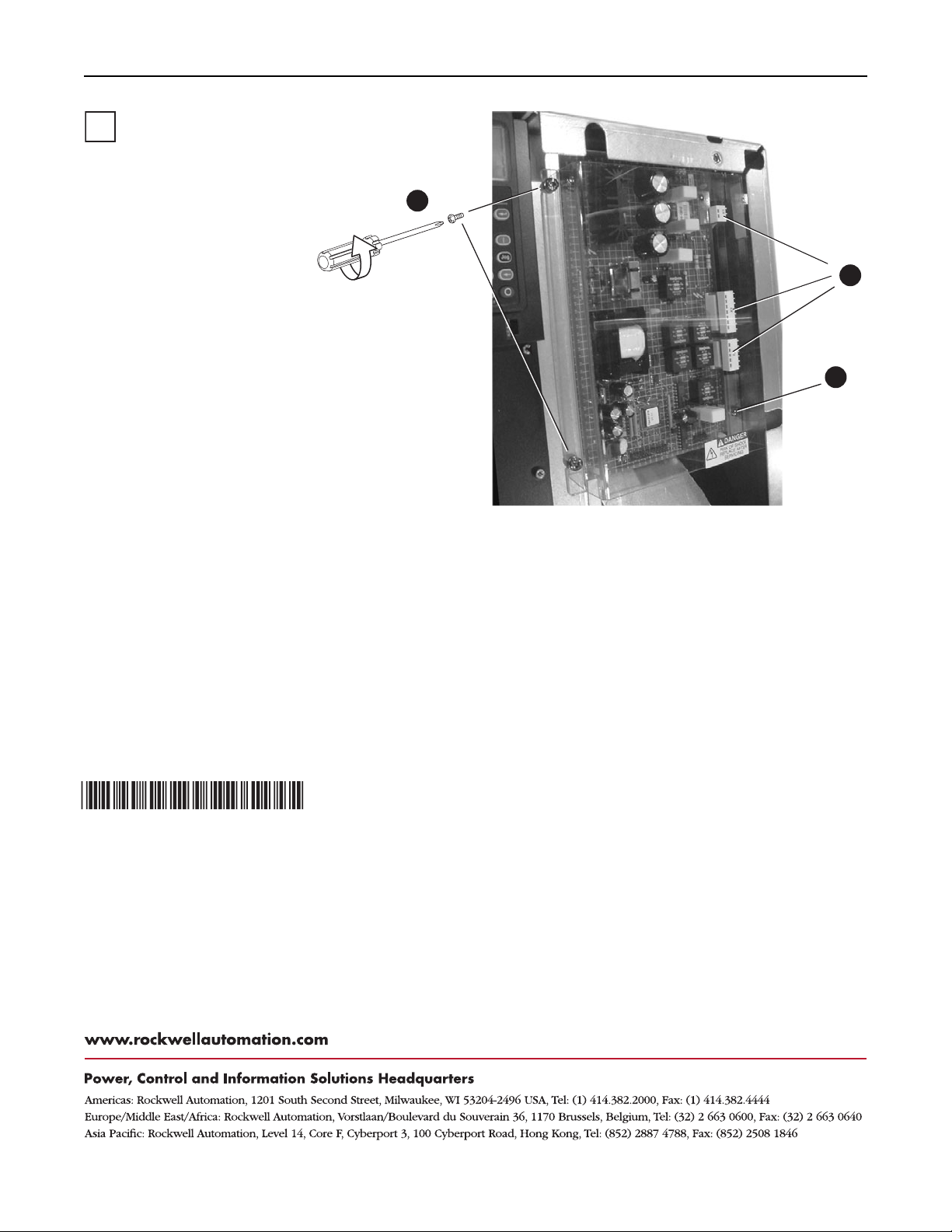
A. Remove the two screws securing the
plastic shield.
A
B. Loosen the screw that secures the fan
assembly (located between the terminal
blocks, see figure).
C. Slide the Precharge Board assembly out
slightly to gain access to the board and
connectors.
D. Disconnect ground wire and remove the
2
)
9
INPUT ACOUTPUT
three connectors. Note connector
location and orientation.
E. Remove board.
B
F. Install new board in reverse order. All
screws should be tightened to 3.2 N-m
(28 lb.-in.).
2
3
A. Remove the screws securing
B. Label and remove the three
C. Remove the four screws
D. Re-assemble in reverse order
Frame 6
the Precharge Board
protective shield. Remove
shield.
cables from the board.
securing the board. Remove
the board.
using the new board. All
screws should be tightened to
3.2 N-m (28 lb.-in.).
A
C
B
x4
Publication RA-IN012A-EN-P – October, 2004 P/N 354787-P01
Copyright © 2004 Rockwell Automation, Inc. All rights reserved. Printed in USA.
 Loading...